Embed Size (px)
Citation preview

Introduction to Microcontrollers
KEVIN JOSE
SPECIAL THANKS TO:
SHIVENDU BHUSHAN
SONU AGARWAL

Things to be covered today…
Embedded System – Introduction, Examples
Microcontrollers - basic featuresInput and output from a micro-controllerProgramming a micro-controllerArduino

Embedded Systems
Gadgets and devices
Self controlled devices
Contains I/O devices, storage devices and a central ‘controller’
Example: Music player
Output
Output Storage Device
Controller
Input

Snake Game, Electromania 2013

Line Following Bot, Techfest 2014

Maze Game, Embedded 2013

Micro-Controllers
Difference between microcontrollers and microprocessors: Microprocessors are simply processing units which need external peripherals (like RAM, ROM etc) but microcontrollers have do not require external peripherals to function (they have internal RAM, flash memory etc.)
Out of several available vendors like Atmel, Intel, ARM, Cypress, etc. We will use Atmel ATmega microcontrollers
Like computers they execute programs. We will use C as the coding language

ATMEGA 8
28 pin IC
23 pins for I/O
5 pins reserved
I/O pins divided into 3 groups of 8* pins, called ports
Ports labelled as B, C and D

I/O Registers
Input / Output is controlled through special variables called “registers”
Registers are actual hardware memory locations inside the μCs with predefined names and sizes
Assigning a value to these registers in the program changes the corresponding hardware configuration. And, these values can be altered multiple number of time at any point in the program.
There are 3 registers that control the I/O pins: DDR, PORT and PIN.
Each port has it’s own registers. Hence, DDRC, PORTC, PINC registers for port C; DDRB, PORTB, PINB for port B and likewise

DDR(Data Direction Register) Decides whether the pin is Input or Output
DDR is an 8 bit register. Each bit corresponds to a particular pin on the associated port
If a bit on the DDR register is 0, then the corresponding pin on the associated port is set as input
Similarly, if the bit is 1, then the pin is set as output
If a pin is configured as input, then it has some floating voltage unless an external voltage is applied
For an output pin, the voltage is fixed to a particular value

Setting Register Values
MSB of DDRB corresponds to the pin A7
• If DDRA = 0b10010110, then:

PORT Register
PORT is also an 8 bit register. The bits on the PORT register correspond to the pins of the associated port in the same manner as in the case of the DDR register.
PORT is used to set the output value.
If the pin is set as output, then a PORT value of 1 will set voltage at that pin to 5V, and PORT value 0 sets the voltage to 0V.
If the pin is configured as an input, PORT value serves the purpose of pull up or pull down.

PIN Register
PIN is a register whose value can be read, but cannot be changed inside the program.
It gives the value of the actual voltage at a particular pin. 1, if the value at the required pin is 5V and 0 for 0V.

Summary
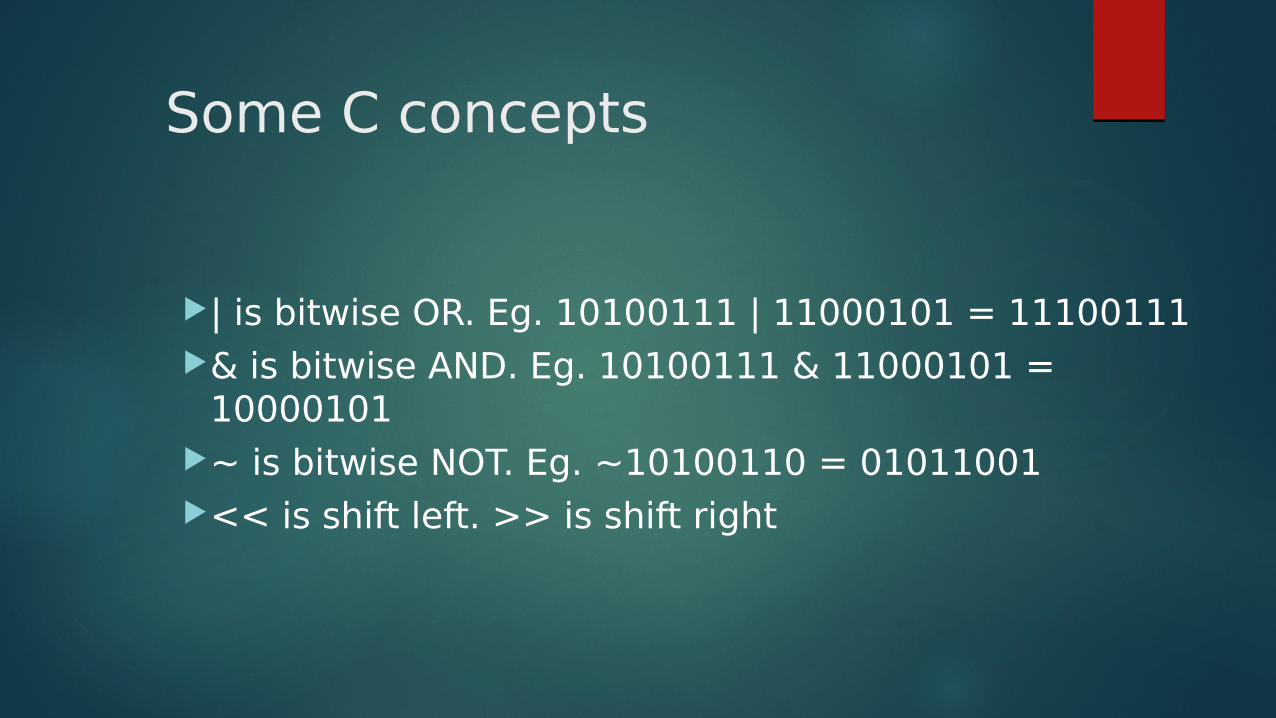
Some C concepts
| is bitwise OR. Eg. 10100111 | 11000101 = 11100111 & is bitwise AND. Eg. 10100111 & 11000101 =
10000101 ~ is bitwise NOT. Eg. ~10100110 = 01011001 << is shift left. >> is shift right

Simplest C program for a micro-controller
int main(){
return 0;
}

Example Program 1
#include <avr/io.h>
int main(){
DDRA = 0b11111111; // or 255 or 0xFF
while(1){
PORTA = PINC;
}
return 0;
}

Example Program 2
#include <avr/io.h> #include <util/delay.h> int main(){ DDRA = 0xFF; while(1){ PORTA = 0xAA; _delay_ms(1000); PORTA = 0x55; _delay_ms(1000); } return 0; }

How to Program MCU?
#Problem: What kind of files MCU can execute ?
#Problem: How to transfer that file to MCU ?
-CVAVR/AVRSTUDI
O->
Extreme Burner

Arduino

Further references
Electronics Club databasehttp://students.iitk.ac.in/eclub/database.php
Official Arduino Referencehttp://arduino.cc/en/Reference/HomePage
eXtreme Electronics AVR tutorialshttp://extremeelectronics.co.in/category/avr-tutorials/