Embed Size (px)
Citation preview

Foxboro Evo™ Process Automation System
Product Specifications
PSS 31H-1B11 B3
Field Control Processor 280 (FCP280)
The Field Control Processor 280 is a distributed, optionally fault-tolerant, field-mounted controller that performs process control and alarming functions according to a user-defined control strategy.
FEATURES
Performs regulatory, logic, timing, and sequential control together with connected Fieldbus Modules (FBMs)
Performs data acquisition and alarm detection and notification
Supports up to 128 Compact or standard 200 Series FBMs, or up to 128 of a combination of 100 Series FBMs and 200 Series FBMs (with no more than 64 100 Series FBMs in this configuration)No Fieldbus Communication Module is required.
No Fieldbus Expansion Module is required for Expanded fieldbus support.
Supports self-hosting mode, which allows the FCP280 to boot itself with a valid control database even without its host workstation
Offers unique, patented, fault-tolerant operation using two control modules to greatly improve reliability relative to other process controllers
Offers on-line image upgrade (OLUG) of a fault-tolerant FCP280 without shutting down the process
Liquid Crystal Display (LCD) displays letterbug and real-time roles and statuses
Connects to The Mesh control network via standard fiber optic or copper 100 Mbps Ethernet cables

PSS 31H-1B11 B3Page 2
Uses a rugged, die cast aluminum housing for mounting in a non-vented field enclosure
Can operate in Class G3 harsh environments CE certified for field mounting in enclosures Each Fieldbus port on FCP280 baseplates
supports either a 2 Mbps or 268 Kbps HDLC fieldbus exclusively
Uses versatile control algorithms and a wide variety of FBMs to provide control capabilities for a broad range of process applications
Supports time synchronization using optional external time from GPS satellites
Uses soft letterbugs configurable via the keys on the FCP280 faceplate.
OVERVIEW
The Field Control Processor 280 (FCP280) is a distributed, optionally fault-tolerant, field-mounted controller module. The FCP280 performs regulatory, logic, timing, and sequential control together with connected Fieldbus Modules. It also performs data acquisition and alarm detection and notification. The FCP280 connects to The Mesh control network via standard fiber optic or copper 100 Mbps Ethernet cables from network adapters installed on its baseplate (shown in Figure 1).
The FCP280 requires Foxboro Evo Control Core Services v9.0 or later. A system with the FCP280 and this software is called a Foxboro Evo Process Automation System.
Figure 1. Fault-Tolerant FCP280 Module Pair Mounted on Vertical Mounted 2-Position FCP280 Baseplate
100 Mbps OrangeDuplex Fiber Cable
To/From Control NetworkEthernet Fiber Switch 1
To/From Control NetworkEthernet Fiber Switch 2
FCP280 Fault-TolerantModule Pair
Network Adapters(Fiber Adapters Shown,
Cooper Adapters available)
Liquid CrystalDisplay
Select Button Down-Arrow Button
Each Fieldbus Port (1-4, Top 1, Bottom 4)can connect to fieldbus with Compact and/or standard
Up-Arrow Button
200 Series FBMs, or 100 Series FBMs in apre-approved configuration

PSS 31H-1B11 B3Page 3
The fault-tolerant version of the FCP280 consists of two processor modules. These modules are installed in adjacent FCP280 slots in a baseplate for high speed communication between the modules.
The FCP280 accepts four PIO channels (that is, four separate HDLC fieldbuses) via the four Fieldbus ports on its baseplate. These four Fieldbuses are referred to collectively as the “Expanded fieldbus.” For a description of the FCP280 baseplates, refer to DIN Rail Mounted Modular Baseplates (PSS 21H-2W6 B4).
The number of FBMs which an FCP280 can support varies depending on the types of FBMs used:
200 Series FBMs exclusively used with FCP280 - Each Fieldbus port on the FCP280 baseplate can connect to a baseplate chain with up to 32 Compact or standard 200 Series FBMs per chain via the 2 Mbps HDLC fieldbus (up to 128 modules).
200 Series and 100 Series FBMs (dual baud configurations) used with FCP280 - The FCP280 can support a total of 64 100 Series FBMs (Y-module) or competitive devices (such as Foxboro Evo System migration FBMs) in one or more baseplate chains, with the remainder of the FCP280’s 128 module limit being 200 Series FBMs, depending on the Fieldbus loading of the FCP280. For example, an FCP280 could support 64 100 Series FBMs and 64 200 Series FBMs (as 128 - 64 = 64). See Figure 2 and Figure 3 below.
NOTECertain competitive migration or supported third-party modules such as DCS Migration fieldbus Modules and Pepperl+Fuchs™ I/O modules may increase this 128 module maximum per FCP280. For the maximum numbers of each of these migration/third-party modules supported by the FCP280, refer to the supported migration products books in Field Control Processor 280 (FCP280) User’s Guide (B0700FW).
When supporting 200 Series and 100 Series FBMs, each Fieldbus port (PIO channel) is dedicated to supporting either a 268 Kbps HDLC fieldbus (for 100 Series FBMs) or a 2 Mbps HDLC fieldbus (for 200 Series FBMs) - not both.
For connections to 100 Series FBMs over 60 m (198 ft), an FBI200 pair is required to extend communications up to 1830 m (6000 ft). See Figure 2 below.
To connect a Fieldbus port to a 268 Kbps HDLC fieldbus directly, the Fieldbus splitter (RH928CV) provides a connector for any Fieldbus port on the FCP280 baseplate, and two Termination Cable Assembly (TCA) termination blocks for the twinaxial cabling from the 100 Series FBMs.
The FCP280 can also communicate with serial and Ethernet devices, such as PLCs, via Field Device System Integrators. This allows you to connect to new device interfaces without any changes to the controller software.
To estimate the FCP280’s processor load, refer to Field Control Processor 280 (FCP280) Sizing Guidelines and Excel Workbook (B0700FY).

PSS 31H-1B11 B3Page 4
.
Figure 2. Typical FCP280 Network Configuration with Mixed 100 Series and 200 Series FBM Functionality (Simplified)
Notes: 1. FCP280 supports up to 128 200 Series FBMs when only 200 Series FBMs are used. When a mix of 100 Series and 200 Series FBMs
FCP FCP280 280
FCP280 Vertical BaseplateFiberadapters
Switch Switch
Fiber optic cabling
FBM
FBM
FBM
FBM
FBM
FBM
FBM
FBM
200 Series FBMs
To Next Baseplate in Chain(Chain supports up to 32200 Series FBMs total);
200 Series FBMs
To Next Baseplate in Chain(Refer to PSS 31H-2COV B3for baseplate chain
FBM
FBM
FBM
FBM
FBM
FBM
FBM
FBM
200 Series FBMs
To Next Baseplate in Chain(Chain supports up to 32200 Series FBMs total)
100 Series FBMs can be connected to anyFieldbus port on FCP280 baseplate, provided
I O I O
1x8 Mounting StructureTo other FBIs
To other FBIs
FieldbusIsolators(FBIs)
100 Series
Twinaxial Cables1 Km (3200 ft) Maximum(P0170GF or P0170GG)
must be supported, it supports up to 64 100 Series FBMs with the remainder of the 128 module limit being 200 Series FBMs.
2. 100 Series FBMs can be connected to any Fieldbus port on the FCP280 baseplate, provided that the overall FBM limit or 64100 Series FBMs is maintained for the FCP280. Up to 64 100 Series FBMs are supported per chain.
The MESH Control Network
200 Series FBMs and/or 200 Series Competitive Migration Modules (See “DEVICES SUPPORTED” on page 8.)
100 Series FBMs and/or 100 Series Competitive Migration Modules (See “DEVICES SUPPORTED” on page 8.) - Up to 64 100 Series FBMs supported per chain
For sizing constraints and devices supported by the FBI100, refer to PSS 21H-2Y16 B4. The FBI200/FBI100 extends the distance of the HDLC fieldbus between the FCP280 and the FBMs up to 1830 m (6000 ft). The FBI200/FBI100 can be used with 200 Series FBMs as well to extend the cabling distances to them.
Copper cablingcan be used as wellwhen copper adaptersare installed in theFCP280 baseplate.
FBI100 pair may be used in place of FBI200s. For sizing constraints and devices supported by the FBI200, refer to PSS 21H-2Y18 B4
As well, FBI200 supports customer-supplied cablesup to 1.83 Km (6000 ft)
that port is used exclusively with 100 Series FBMs.For direct termination cable assembly (TCA)connections to the Fieldbus ports (i.e. withoutFBI200s), refer to the next figure.
3. An FBI200 may be included on this connection to extend the distance between the 100 Series FBIs and the FCP280 baseplate. The FCP280 can communicate on the 268 Kbps HDLC fieldbus up to 60 m (198 ft).When communicating with a 268 Kbps HDLC fieldbus only, the FCP280 can communicate on this fieldbus up to 1 km (3200 ft).
For example, 64 100 Series FBMs and 64 200 Series FBMs (as 128 - 64 = 64). Each PIO channel must be dedicated to either
Termination Cable AssemblyTermination Block (RH928CV)
FCM2F2/4/10 modules maybe installed in the baseplates ina chain to extend the distanceas explained in PSS 31H-2Y3 B3.
Also, see Note 3.
a 268 Kbps or 2 Mbps HDLC fieldbus.
Compact StandardStandard
configurations with Compact200 Series baseplates)
F
B
M
F
B
M
F
B
M
F
B
M
F
B
M
F
B
M
F
B
M
F
B
M
F
B
M
F
B
M
F
B
M
F
B
M
F
B
M
F
B
M
F
B
M
F
B
M

PSS 31H-1B11 B3Page 5
.
Figure 3. Typical FCP280 Network Configuration with Exclusive 100 Series FBM Functionality (Simplified)
FCP FCP280 280
FCP280 Vertical Baseplate
Fiberadapters
Switch Switch
Fiber opticcabling -
AB
I O I O
1x8 Mounting StructureTo other FBIs
To other FBIs
Fieldbus Isolators (FBIs)100 Series
The MESH Control Network
100 Series FBMs and/or 100 Series Competitive Migration Modules (See “DEVICES SUPPORTED” on page 8.)
AB
I O I O
1x8 Mounting StructureTo other FBIs
To other FBIs
Termination Cable AssemblyTermination Block (RH928CV)
AB
Twinaxial Cables1 Km (3200 ft) Maximum(P0170GF or P0170GG)
AB
Copper cablingcan be used as wellwhen copper adaptersare installed in theFCP280 baseplate.
Notes: 1. FCP280 supports up to 64 100 Series FBMs total. Up to 64 100 Series FBMs are supported per baseplate chain.
- See Note 2
For sizing constraints and devices supported by the FBI100, refer to PSS 21H-2Y16 B4. The FBI200/FBI100 extends the distance of the HDLC fieldbus between the FCP280 and the FBMs up to 1830 m (6000 ft).
FBI100 pair may be used in place of FBI200s. For sizing constraints and devices supported by the FBI200, refer to PSS 21H-2Y18 B4
Twinaxial cables over 1 Km (3200 ft) are customer supplied.
100 Series FBMs can be connected to any Fieldbus port on FCP280baseplate, provided that port is used exclusively with 100 Series FBMs.
3. The RH928CV splitter has a 3 m (9.8 ft) cable between the Fieldbus port connector and TCA termination block.
2. FBI200 is needed only to extend the distance between the 100 Series FBIs and the FCP280 baseplate.The FCP280 can communicate on the 268 Kbps HDLC fieldbus up to 60 m (198 ft).When communicating with a 268 Kbps HDLC fieldbus only, the FCP280 can communicate on this fieldbus up to 1 km (3200 ft).
Refer to B0700FW for the listof switches which are not supportedby the FCP280.

PSS 31H-1B11 B3Page 6
FIBER AND COPPER NETWORK ADAPTERS
FCP280 modules connect to a pair of fiber or copper adapters (see Figure 4) which each connect to one Ethernet switch in The Mesh control network. The FCP280 baseplate passes inbound traffic from either of the two switches to both FCP280s, and pass outbound traffic from the primary FCP280 module to either switch.
Figure 4. Fiber Optic and Copper Network Adapters
The fiber or copper adapters mount on the FCP280 baseplate as shown in Figure 1 on page 2. They receive their power from the baseplate.
REMOTE MOUNTING
The FCP280 simplifies the Foxboro Evo Process Automation System architecture, maintaining control while only requiring housing (via field enclosures), host workstations with Foxboro Evo Control Core Services v9.0 or later, and Ethernet switches for communication via The Mesh control network architecture, described in PSS 21H-7C2 B3.
The field-mounted FCP280 is an integral part of the highly-distributed control network where controllers are closely aligned to specific process units mounted in close proximity to their I/O and the actual equipment being controlled. Coordination between process units takes place via a fiber optic 100 Mbps Ethernet network.
The FCP280 and its network adapters are packaged in a rugged, die cast aluminum housing that does not require venting due to its efficient design. The FCP280 and its network adapters are CE certified, and it can be mounted without expensive special cabinets to prevent electronic emissions. The FCP280, network adapters, and baseplate can be mounted in Class G3 harsh environments.
ENHANCED RELIABILITY (FAULT-TOLERANCE)
The unique and patented fault-tolerant operation of the FCP280 improves reliability relative to legacy process controllers. The fault-tolerant version of the FCP280 consists of two modules operating in parallel, with two Ethernet connections to The Mesh control network. The two FCP280 modules, married together as a fault-tolerant pair, provide continuous operation of the controller in the event of virtually any hardware failure occurring within one module of the pair.
Both modules receive and process information simultaneously, and faults are detected by the modules themselves. One of the significant methods of fault detection is comparison of communication messages at the module external interfaces. Messages only leave the FCP280 when both FCP280s agree on the message being sent (bit for bit match). Upon detection of a fault, self-diagnostics are run by both modules to determine which module is defective. The non-defective module then assumes control without affecting normal system operations.
This fault-tolerant solution has the following major advantages over controllers that are merely redundant:
No bad messages are sent to the field or to applications using controller data because no message is allowed out of the controller unless both modules match bit for bit on the message being sent.
Fiber Adapter (RH924WA) Copper Adapter (RH924UQ)

PSS 31H-1B11 B3Page 7
The secondary controller is synchronized with the primary one, which ensures up to the moment data in the event of a primary controller failure.
The secondary controller will have latent flaws detected prior to any switchover because it is performing exactly the same operations as the primary controller.
UPGRADE OPTIONS
Multiple options are available for replacing existing control processors with the FCP280. A fault-tolerant FCP280 may replace a fault-tolerant FCP270 or ZCP270. It may import the CP database from the CP270 it is replacing, for compatibility and minimal configuration time.
As well the FCP280 provides an increase in performance and block processing capacity over the CP270s. When replacing FCP270s, the FCP280 eliminates the need for FEM100 hardware.
For ease of replacement, the fault-tolerant or non-fault-tolerant FCP280 in its baseplate has the same dimensions as the fault-tolerant or non-fault-tolerant FCP270 in its baseplate.
Cabling the 100 Series FBMs or Migration products to an FCP280 baseplate consists of extending the remote 268 Kbps fieldbus between enclosures. This is accomplished using termination cable assemblies (TCAs) and Fieldbus Isolators (FBIs) to provide connections between primary and extended fieldbus segments.
The optional FBI200 can extend the 2 Mbps HDLC fieldbus between 200 Series FBMs from 60 m (198 ft) up to 305 m (1000 ft). As well, it can extend the 268 Kbps HDLC fieldbus between 100 Series FBMs from 60 m (198 ft) up to 1830 m (6000 ft).
As with earlier generations of control processors, up to 64 100 Series FBMs (including expansion modules) attach to Fieldbus ports through Fieldbus Isolators. (Up to 24 100 Series FBMs, excluding expansion modules, can connect to each isolator.
However, the expansion modules are considered 100 Series FBMs in this “64 100 Series FBMs” maximum discussed in this PSS.)
Available upgrade scenarios are available in Field Control Processor 280 (FCP280) User’s Guide (B0700FW).
FBI200 FIELDBUS ISOLATOR/FILTER
The FBI200 Fieldbus Isolator/Filter extends the length of the 268 Kbps module Fieldbus from the FCP280 to 100 Series FBMs and similar competitive migration modules up to 1830 m (6000 ft) over a twinaxial Fieldbus cable. See Figure 2 on page 4.
It can also extend the 2 Mbps HDLC fieldbus to 200 Series FBMs up to 305 m (1000 ft).
For more information on the FBI200, refer to FBI200 Fieldbus Isolator/Filter (PSS 21H-2Y18 B4).
FIRMWARE UPGRADES WHILE ON-LINE
For fault-tolerant FCP280 modules, on-line image upgrade replaces the executable image (operating system) of a running FCP280 with a newer image without having to shut down the equipment being controlled by the FCP280.
TIME SYNCHRONIZATION, SOE, TDR/TDA
The Foxboro Evo Process Automation System supports time synchronization using either an externally maintained optional source of Universal Coordinated Time (UTC) from GPS satellites or an internal source using proprietary software. FCP280s that receive time updates via the external time source synchronize their FBMs to 1 ms. For more information on time synchronization, refer to Time Synchronization Overview (PSS 21S-1C2 B3).
Time stamping is used for alarm messages, values sent to the historian, and the Sequence Of Events (SOE) and Transient Data Recorder (TDR), and Transient Data Analyzer (TDA) features.

PSS 31H-1B11 B3Page 8
SOE data are discrete points that are time stamped at the FBM, optionally to 1 ms, and sent to the workstation on a change basis. TDR/TDA data are analog or digital points that are time stamped at the FBM and sent to the workstation every 10 ms. These features are supported by client software in the workstation. For information on this new software, refer to Field Control Processor 280 (FCP280) Integrated Control Software (PSS 31S-3B3 B3).
SOFTWARE CONTROL FEATURES
The FCP280 performs regulatory, logic, timing, and sequential control, as well as data acquisition, alarm detection, and alarm notification. Process variables are controlled using time-proven algorithms (mathematical computations performing specific functions). The algorithms are contained in functional control blocks, which on-site process engineers configure to implement the desired control strategies.
The versatility of the algorithms, coupled with the variety of FBMs available, provides control capabilities suited to a broad range of process applications. Control strategies ranging from simple feedback and cascade loops to highly sophisticated feedforward, nonlinear, and complex characterization control schemes are readily implemented.
The FCP280 also supports the following features:
Setting and reading the FCP280 letterbug via the buttons on the faceplate
Alarm enhancements to function blocks:re-alarming on changes to alarm priority,re-alarming based upon a configurable time delay deadband, and alarm suppression based upon time
Optional UTC external time synchronization
Improved controller performance
Optional self-hosting mode allows the FCP280 to start up and run, executing its configured control
scheme using the checkpoint file stored in flash memory. This allows the FCP280 to boot itself with a valid control database even if its host workstation is not present.
Support for high speed capabilities such as ladder logic, Motor Driven Actuator Controller (MDACT), and Distributed Proportional Integral Derivative functionality (DPIDA)
DEVICES SUPPORTED
The FCP280 supports the following devices on the 2 Mbps fieldbus:
All Compact and standard 200 Series FBMs (FBM201, FBM202, and so forth), which can support many types of intelligent field devices, including those on FOUNDATION fieldbus, PROFIBUS, HART, and DeviceNet networks
Field Device Systems Integrator (FDSI) modules
Intrinsically Safe I/O Subsystem (ISCM) - refer to PSS 21H-2Y6 B4).
DCS Migration fieldbus Modules for Siemens APACS+ Systems
DCS Migration fieldbus Modules for
Westinghouse WDPF® Systems
DCS Migration fieldbus Modules for Fisher's PROVOX® Series 20 Migration with HART
DCS Migration fieldbus Modules for Honeywell® TDC 2000 Systems with HART.
The FCP280 supports the following devices on the 268 Kbps fieldbus:
100 Series FBMs (FBM01, FBM02, and so forth)
SPECTRUM™ Migration Integrators
SPEC 200™ Control Integrators
SPEC 200 MICRO™ Control Integrators
SPEC 200 CCM Control Integrators
PSS 31H-1B11 B3Page 9
The Foxboro Gas Chromatograph is not supported.
The FCP280 supports the 100 Series Fieldbus Module Upgrade subsystem, with the optional FBI200A modules. Refer to 100 Series Fieldbus Module Upgrade Subsystem OverviewPSS 21H-2W1 B4).
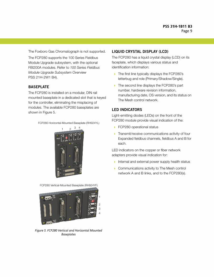
BASEPLATE
The FCP280 is installed on a modular, DIN rail mounted baseplate in a dedicated slot that is keyed for the controller, eliminating the misplacing of modules. The available FCP280 baseplates are shown in Figure 5.
Figure 5. FCP280 Vertical and Horizontal Mounted Baseplates
LIQUID CRYSTAL DISPLAY (LCD)
The FCP280 has a liquid crystal display (LCD) on its faceplate, which displays various status and identification information:
The first line typically displays the FCP280’s letterbug and role (Primary/Shadow/Single).
The second line displays the FCP280’s part number, hardware revision information, manufacturing date, OS version, and its status on The Mesh control network.
LED INDICATORS
Light-emitting diodes (LEDs) on the front of the FCP280 module provide visual indication of the:
FCP280 operational status
Transmit/receive communications activity of four Expanded fieldbus channels, fieldbus A and B for each.
LED indicators on the copper or fiber network adapters provide visual indication for:
Internal and external power supply health status
Communications activity to The Mesh control network A and B links, and to the FCP280(s).
FCP280 Vertical-Mounted Baseplate (RH924YF)
FCP280 Horizontal-Mounted Baseplate (RH924YL)
1 2 3 4
1
2
3
4

PSS 31H-1B11 B3Page 10
FUNCTIONAL SPECIFICATIONS
Processor Type
CONTROL PROCESSOR
ARM® System on a Chip (SOC) with stored programs, using high-speed communication capability.SIZE
128 MB SDRAM128 MB flash memoryERROR DETECTION
ECC providing single-bit error detection and correction as well as multiple-bit error detection.
Process I/O Communications (with FBMs)
MODULE FIELDBUS
TypeHDLCTransmission Rate2 Mbps for 200 Series FBMs or268 Kbps for 100 Series FBMs
Process I/O Capacity
200 SERIES FBMS
Up to 32 per Expanded fieldbus - up to 128 FBMs over all four Expanded fieldbuses when used exclusively with 200 Series FBMs. When used with a mix of 100 Series and 200 Series FBMs, up to 64 100 Series FBMs (Y-module) or competitive devices (such as Foxboro Evo System migration FBMs) with the remainder of this 128 module limit being 200 Series FBMs, depending on the Fieldbus loading of the FCP280.For example, an FCP280 may support 64 100 Series FBMs and 64 200 Series FBMs (as 128 - 64 = 64) over separate Expanded fieldbuses.Refer to Field Control Processor 280 (FCP280) Sizing Guidelines and Excel Workbook (B0700FY) for sizing constraints.Competitive Migration ModulesRefer to the device specific Product Specification Sheets.
Process I/O Capacity (Cont.)
100 SERIES FBMS
64 maximum (over one or more Fieldbus ports on the baseplate) depending on control processor sizing constraints (refer to Field Control Processor 280 (FCP280) Sizing Guidelines and Excel Workbook (B0700FY)).Competitive Migration ModulesRefer to the device specific Product Specification Sheets.
Memory Allocation for Blocks15.75 MBMaximum Number of Blocks ConfiguredThe maximum number of control blocks that can be configured for the FCP280 (or fault-tolerant FCP280 pair) is 8000(1).
Block Executions Per Second16,000 blocks/second, maximum
Maximum Number of Blocks ProcessedThe number of blocks that can be processed per block processing cycle (BPC) time interval depends on scan periods and block type selection. These blocks include all types (control blocks, ECBs, compounds, data blocks, and so forth). For sizing guidelines, refer to Field Control Processor 280 (FCP280) Sizing Guidelines and Excel Workbook (B0700FY).
Minimum Block Processing Cycle (BPC)50 ms
Sequence Block Size32 KB maximum for each block
(1) Seven of these 8000 blocks are pre-defined, leaving a total of 7993 blocks that you can configure for the FCP280. Compounds and ECBs all count as blocks as well.

PSS 31H-1B11 B3Page 11
FUNCTIONAL SPECIFICATIONS (CONTINUED)
Maximum Number of IPC Connections231; 200 connections for source points; 30 connections for sink points; 1 connection for internal use only.
An IPC connection provides the means to exchange continuous process control information. A Source point is defined as a connection to a destination device that can have data sourced by a given CP. Thus an FCP280 can provide data to up to 200 destination stations.A Sink point is defined as an external point to which the FCP280 can connect to acquire process control data. The FCP280 can receive continuous updates from up to 30 other data sources.
Maximum Number of OM Sink Lists75A Sink list is a list of items to be delivered to particular destination. These lists provide an efficient way to group updates to a given destination.
Maximum OM Scanner Database18,000 points for BPC ≥ 200 ms7,500 points for BPC ≤ 100 msThe Object Manager (OM) scanner database is the total of all points in the control scheme for which the CP is scanning and providing updates.
Maximum Number of OM Sink Points11,500The OM sink point limitations refer to the number of points that can be received from outside sources.
Configurable Block Periods0.05, 0.1, 0.2, 0.5, 0.6, 1, 2, 5, 6, 10, 30 seconds1, 10, 60 minutes
Block Processing Cycle0.05, 0.1, 0.2, 0.5 and 1.0 seconds, selectable at system configuration time
Time to Marry Fault-Tolerant ModulesLess than 0.5 seconds
Alarm Queue Entry Size20,000 entries (640,000 bytes)Alarms have text strings associated with each event. This is the maximum number of alarms that can be configured and the maximum number of characters that can be accommodated in the alarm text.
Internal DiagnosticsSelf-checking performed at power-up. Run-time checks and the watchdog timer function performed during operation.When FCP280s are configured as an fault-tolerant pair, constant synchronization checking and message compare operations are also used to detect hardware faults.
Power Requirements
INPUT VOLTAGE (REDUNDANT VOLTAGE)
24 V dc typicalCONSUMPTION (PER NON-FAULT-TOLERANT
MODULE)
8.5 W, maximum
FCP280
30 IPC connections 200 IPC connections

PSS 31H-1B11 B3Page 12
FUNCTIONAL SPECIFICATIONS (CONTINUED)
Regulatory Compliance
ELECTROMAGNETIC COMPATIBILITY (EMC)
European EMC Directive 2004/108/ECMeets:
EN 61326-1 Immunity requirements for industrial locationsCISPR 11, Industrial Scientific and Medical (ISM) Radio-frequency Equipment - Electromagnetic Disturbance Characteristics Limits and Methods of MeasurementMeets Class A LimitsIEC 61000-4-2 ESD ImmunityContact 4 kV, air 8 kVIEC 61000-4-3 Radiated Field Immunity10 V/m at 80 to 1000 MHz, 3 V/m at 1.4 to 2.0 GHz, 1 V/m at 2.0 to 2.7 GHzIEC 61000-4-4 Electrical Fast Transient/Burst Immunity 2 kV on I/O, dc power and communication linesIEC 61000-4-5 Surge Immunity2 kV on ac and dc power lines; 1 kV on I/O and communications linesIEC 61000-4-6 Immunity to Conducted Disturbances Induced by Radio-frequency Fields3 V (rms) at 150 kHz to 80 MHz on I/O, dc power and communication linesIEC 61000-4-8 Power Frequency Magnetic Field Immunity30 A/m at 50 and 60 Hz
PRODUCT SAFETY
Underwriters Laboratories (UL) for U.S. and CanadaUnderwriters Laboratories (UL) for U.S. and Canada UL/UL-C listed as suitable for use in Class I, Groups A-D; Division 2; enclosure based systems when connected to specified DIN rail mounted Fieldbus Modules as described in the DIN Rail Mounted Subsystem User's Guide (B0400FA)Communications circuits also meet the requirements for Class 2 as defined in Article 725 of the National Electrical Code (NFPA No.70) and Section 16 of the Canadian Electrical Code (CSA C22.1). Conditions for use are as specified in the DIN Rail Mounted Subsystem User's Guide (B0400FA).
EUROPEAN LOW VOLTAGE DIRECTIVE
2006/95/EC AND EXPLOSIVE ATMOSPHERES
(ATEX) DIRECTIVE 94/9/EC
ATEX (DEMKO) Ex nA IIC T4 Gc certified when connected as described in the DIN Rail Mounted Subsystem User’s Guide (B0400FA). For use in an enclosure suited for an ATEX Zone 2 classified area.
SECURITY
Wurldtech Achilles Certification™ Level 1

PSS 31H-1B11 B3Page 13
ENVIRONMENTAL SPECIFICATIONS(2)
Operating
TEMPERATURE
0 to 60°C (32 to 140°F)
NOTEInvensys recommends the use of the FCP280 vertical-mounted baseplate (RH924YF) on vertical DIN rails for more efficient cooling of the FCP280.
RELATIVE HUMIDITY
5 to 95% (Noncondensing)ALTITUDE
-300 to +3,000 m (-1,000 to +10,000 ft)CONTAMINATION
Class G3 (Harsh) as defined in ISA Standard, S71.04. No effect on functionality after simulated 10-year exposure to mixed gas testing per EIA Standard 364-65A, Class III.The FCP280 has Conformal Coating.VIBRATION
0.5 g (5 to 500 Hz)
Storage
TEMPERATURE
-40 to +70°C (-40 to +158°F)RELATIVE HUMIDITY
5 to 95% (Noncondensing)ALTITUDE
-300 to +12,000 m (-1,000 to +40,000 ft)
(2) The environmental limits of this module may be enhanced by the type of enclosure containing the module. (Refer to the applicable Product Specification Sheet (PSS) which describes the specific type of enclosure that is to be used.)

PSS 31H-1B11 B3Page 14
PHYSICAL SPECIFICATIONS
ConfigurationSingle processor module. The fault-tolerant version consists of two processor modules, with an interconnecting fault-tolerant connector integral to the baseplate.
MountingMay be placed in device specific 2-position baseplates designed for horizontal or vertical mounting - see Figure 5 on page 9.For the fault-tolerant FCP280, the two modules must be mounted in dedicated slots to allow for interconnecting fault-tolerant communication.
Dimensions - Module
HEIGHT
105 mm (4.13 in)116 mm (4.59 in) including mounting lugsWIDTH
51.8 mm (2.04 in)DEPTH
147 mm (5.80 in)
Figure 6. FCP280 Dimensions
Mass (Maximum0.8 kg (1.78 lb) for a single, non-fault-tolerant module.
Part Number
FCP280
RH924YAFCP280 HORIZONTAL-MOUNTED BASEPLATE
RH924YLFCP280 VERTICAL-MOUNTED BASEPLATE
RH924YFFIBER ADAPTER
RH924WACOPPER ADAPTER
RH924UQSPLITTER ADAPTERS
Twinaxial Fieldbus SplitterRH928CVRedundant Module Fieldbus Cable AdapterRH924ZJ - For use when the FCP280 is in the middle of a 200 Series baseplate chainRH928CY - Enables the use of redundant module Fieldbus cables between baseplates to split and terminate the Modular Fieldbus and optional time strobe signalsTime Strobe AdapterRH924ZQ
105 mm4.13 in
116 mm4.59 in
(includingmountinglugs)
51.8 mm2.04 in
147 mm5.8 in

PSS 31H-1B11 B3Page 15
PHYSICAL SPECIFICATIONS (CONTINUED)
Ethernet Switch to FCP280 Cabling
CABLING CONNECTORS
Fiber AdapterTwo ceramic type LC connectors on one end (for network adapters) with an MT-RJ connector on the other end (for switch)Copper AdapterRJ-45 connectors on both ends
FIBER OPTIC CABLE
Cable MaterialMultimode fiber (MMF) 62.5/125 µm plenumCable LengthsUp to 50 m (164 ft) – Invensys supplied. Refer to “Network Cabling for FCP280 Network Adapters” in B0700FW for the appropriate specifications of allowed fiber optic cabling.Greater than 50 m – user suppliedMaximum Length2 km (6,560 ft) from the Ethernet switch to the FCP280.
COPPER CABLE
Cable Material1000Base-T CAT5 copper Ethernet cableCable LengthsUp to 100 m (328 ft) – Invensys supplied. Refer to “Network Cabling for FCP280 Network Adapters” in B0700FW for the appropriate specifications of allowed copper cabling.Greater than 100 m – user suppliedMaximum Length100 m (328 ft) from the Ethernet switch to the FCP280.
Cabling – 2 Mbps Fieldbus
FCP280 FIELDBUS WITHOUT FCM2Fs
The cable length of each individual Expanded fieldbus cannot exceed 60 m (198 ft).
FCP280 FIELDBUS WITH FCM2Fs
Each FCP/FCM drives a segment of interconnected baseplates of up to 60 m (198 ft). Up to four pairs of FCM2Fxs can be used in each individual fieldbus in the Expanded fieldbus.
FCP280 FIELDBUS WITH FBI200
The cable length from the FCP280 to FBI200 is up to 305 m (1000 ft), and the length from the FBI200 to the last baseplate in the chain is 60 m (198 ft).(This represents the distance for one HDLC fieldbus in the Expanded Fieldbus.)Refer to FBI200 Fieldbus Isolator/Filter (PSS 21H-2Y18 B4) for additional FBI200 configurations and restrictions.

PSS 31H-1B11 B3Page 16
PHYSICAL SPECIFICATIONS (CONTINUED)
Cabling – 268 Kbps Fieldbus(3)
MAXIMUM LENGTH
To 200 Series FBMs via FBI200Total Length of Cabling between FCP280 and FBI200 Plus the Total Length of the 2 Mbps Module Fieldbus (for 200 Series FBMs) - 60 m (198 ft) maximumTo 100 Series FBMs via FBI200Between FCP280 and FBI200 - 60 m (198 ft) maximumFrom FBI200s to 100 Series FBMs in last Mounting Structure - 1830 m (6000 ft) maximumTo 100 Series FBMs, Direct Connection
2 Mbps and 268 Kbps Mixed ConfigurationsFrom FCP280 to 100 Series FBMs in last Mounting Structure - 60 m (198 ft) maximum268 Kbps Only ConfigurationsFrom FCP280 to 100 Series FBMs in last Mounting Structure - 1 Km (3200 ft) maximum
CABLE
Twinaxial, shielded
(3) The FCP280 baseplate Fieldbus ports support direct connection to the 268 Kbps fieldbus via the splitter (RH928CV).

PSS 31H-1B11 B3Page 17
RELATED PRODUCT SPECIFICATION SHEETS
For reference purposes, Table 1 lists the Product Specification Sheets (PSSes) for additional hardware and software elements in the DIN rail mounted subsystem.
Table 1. Related Product Specification Sheets
PSS Number Title
PSS 21H-2W1 B3 DIN Rail Mounted Subsystem Overview
PSS 21H-2W1 B4 100 Series Fieldbus Module Upgrade Subsystem Overview
PSS 31H-2W2 B3 DIN Rail Mounted Equipment Agency Certification
PSS 31H-2W3 B4 DIN Rail Mounted Power Supplies - FPS400-24
PSS 21H-2W4 B4 Termination Assembly Adapter Modules for 100 Series Upgrade
PSS 21H-2W6 B4 DIN Rail Mounted Modular Baseplates
PSS 31H-2W7 B4 DIN Rail Mounted Power Supplies - FPS240-24 and FPS120-24
PSS 21H-2W8 B4 100 Series Conversion Mounting Structures
PSS 31H-2COV B3 Compact 200 Series I/O Subsystem Overview
PSS 31H-2W12 B3 DIN Rail Mounted Compact 200 Series I/O Equipment, Agency Certifications
PSS 31H-2C480 B4 Compact Power Supply - FPS480-24
PSS 21H-2Y6 B4 Intrinsically Safe I/O Subsystem
PSS 21H-2Y16 B4 FBI100 Fieldbus Isolator/Filter
PSS 21H-2Y17 B4 FBI200A Fieldbus Isolator/Filter
PSS 21H-2Y18 B4 FBI200 Fieldbus Isolator/Filter
PSS 21H-2GOV B3 G-Series Enclosures Overview
PSS 21H-7C2 B3 The Mesh Control Network Architecture
PSS 21S-1C2 B3 Time Synchronization Overview
PSS 31S-3B3 B3 Field Control Processor 280 (FCP280) Integrated Control Software

PSS 31H-1B11 B3Page 18

PSS 31H-1B11 B3Page 19

PSS 31H-1B11 B3Page 20
Invensys 10900 Equity DriveHouston, TX 77041United States of Americahttp://invensys.com
Global Customer SupportInside U.S.: 1-866-746-6477Outside U.S.: 1-508-549-2424 or contact your local Invensys representative.Website: https://support.ips.invensys.com
Invensys, Foxboro, Foxboro Evo, Foxboro Evo logo, and Invensys logo are trademarks of Invensys Limited, its subsidiaries, and affiliates.All other brands and product names may be the trademarks of their respective owners.
Copyright 2014 Invensys Systems, Inc. All rights reserved. Unauthorized duplication or distribution is strictly prohibited.
MB 031 0414