Embed Size (px)
Citation preview
FORTUNA
OPTIMAT 2
BedienungsanleitungOperating Manual
Seriennummer:Serial-no.:
Datum:Date:

2
Copyright 2006 byPoulten & Graf GmbHAm Bildacker 3-797877 WertheimGermany
Alle Rechte vorbehalten, insbe-sondere das Recht an den Abbil-dungen und den Originaltexten zurGänze und in Teilen für jedwedeVervielfältigungsmethode.
All rights reserved, especially therights to illustrations and originaltexts in their whole and in part, forany and all reproduction.
63
3
Index D
SeitenVorwort / Übersicht 4 - 5Pumpen-Installation 6 - 7Programmierung als Einzelstation 8 - 10Programmierung als Doppelstation 11 - 12Fehlerkontrolle / Fehlerbehebung 13Anhang A - Geschwindigkeiten-Tabelle 15Anhang B - Schnittstellenbeschreibung 15 - 30Seriennummer / Fabrikationsdatum 64
Index GB
Preface / Overview 32 - 33Pump installation 34 - 35Programming of the single station 36 - 38Programming of the double station 39 - 40Troubleshooting 41Annex A - max. speed chart 43Annex B - interface protocol 44 - 58Serial number / Fabrication date 64
Index NL
Programmeren FORTUNA OPTIMAT 2 60
62
8) Acceler :acceleratie bij het begin van de aanzuigprocedure (0-900)
9) Acceler :acceleratie bij het begin van de doseerprocedure (0-900)
10) Decelar :remsnelheid aan het eind van de aanzuigprocedure (0-900)
11) Decelar :remsnelheid aan het eind van de doseerprocedure
12) Next memory:Ingave 0 programmeren is beëindigd en er kan eventueel
gestart worden
Ingave 1-15 het zojuist ingegeven programma moetgekloppeld worden aan nog een anderprogrammanummer.
Geef nu F4.
!! Druk je tijdens één van de voorafgaande stappen op F3 (Exit)dan ben je alle geprogrammeerde waarde verloren en moet jede procedure opnieuw starten!!
Met behulp van F1 kunnen we nu de procedure starten.
4
VorwortWir danken Ihnen für den Erwerb einer FORTUNA OPTIMAT Dosier-station. Sie haben eine gute Wahl getroffen. Unsere mehr als 20-jähri-ge Erfahrung im Bau von Dosiersystemen, garantiert Ihnen ein hohesMaß an Produktqualität und Sicherheit bei der Arbeit.
Um Qualität und Sicherheit der Dosierstation auch über einen langenZeitraum erhalten zu können, bedarf es korrekter Bedienung und Pflege.
Bitte lesen Sie deshalb die Bedienungsanleitung vor Verwendung derDosierstation und beachten Sie unbedingt die Warnhinweise sowie dieeinschlägigen Vorschriften.
Die Lieferung umfasst: 1 FORTUNA OPTIMAT 2 Dosierstation mit inte-griertem Programmierterminal. Die Optionen entnehmen Sie bitte unseremKatalog.
1 Die Modellvarianten der FORTUNA OPTIMAT 2Dosierstationen
150.000-2 FORTUNA OPTIMAT 2 COMFORTmit integriertem Programmierterminal,ohne Schnittstelle
150.000-3 FORTUNA OPTIMAT 2 COMFORT / Smit integriertem Programmierterminal undStandard-Schnittstelle RS 232
Option: 150.000-10 Schnittstelle RS 232 nur für Kat.Nr. 150.000-2 150.000-20 Schnittstelle RS 485 nur für Kat.Nr. 150.000-2 150.000-30 Schnittstelle CAN nur für Kat.-Nr. 150.000-2
Die Dosierstation ist aufnahmefähig für eine FORTUNA OPTIMAT
Dosierpumpe (siehe auch Zubehörkatalog). Das Modell 150.000-3FORTUNA
OPTIMAT
2 COMFORT / S ist mit weiteren FORTUNA
OPTIMAT 2 COMFORT / S Dosierstationen vernetzbar. Peripherie-
Geräte wie z.B. Analysen-Waagen, Drucker oder Meßgeräte sindanschließbar.
61
Heb je een keuze gemaakt druk dan op F4 ENTER.
Je komt nu weer in het hoofdmenu en kunt eventueel naar een andergeheugen door de vorige stap nogmaals toe te passen.
We gaan nu programmeren:
Druk nogmaals op F4
1) Op het display verschijnt b.v. vol.: 0.000Met behulp van de toetsen en kun je de cursor op dejuiste plaatsen brengen om je volume(s) in te geven.Met behulp van de en toetsen geef je nu het te doserenvolume aan (0.9999999 ml). Heb je het juiste volumeingesteld, dan F 4 en ga naar de volgende stap.
2) Op het scherm verschijnt velo. ......Je kunt nu op dezelfde manier als hiervoor beschreven deinnamesnelheid programmeren. Na instellen op F 4 drukken.De procedures zoals hiervoor aangegeven met ....F4 geldt, indien niet ander vermeld, voor alle volgendestappen.
3) velo Hiermee kun je de uitstroomsnelheid instellen.
4) Pre delay:tijd tussen druk op ‘Start’ en de dosering (0-9999 sec.)
5) Top delay:standtijd van zuiger in hoogste positie (0-9999 sec)
6) Repeat:aantal keren dat je wilt doseren (0-99999 sec)
7) Input = output: Inname volume = doseervolumeToets Input > output: Inname volume > doseervolume

5
STO
P
2 Programmier-Terminal
A Funktionstasten ADie Funktionstasten B F1 - F4ändern sich je nach F D CProgrammverlauf.
B LCD-Display E2-zeiliges Display mitvier Feldern für dieFunktionstasten, hinter-grundbeleuchtet. G
C Pfeil-Tasten Mit den Pfeil-Tasten und kann derangezeigte Wert vergrößert oder verringertwerden. Mit den Pfeil-Tasten und bewegen Sie den Cursor auf die entsprechen-de Position, um Werte einzugeben oder zu ändern.
D Memory LED 15 Leucht-Dioden zur Anzeige des gewähltenProgramms.
E Motor-Kontrolle Unterbricht laufendes Programm.
Durch die Tasten: (aufwärts) und (abwärts) kann der Motor auch
manuell betrieben werden .
F Pumpen-Halterung Die obere Pumpenhalterung ist mit dem Motorund dem Kolben der Pumpe verbunden.
G Pumpen-Halterung Die untere Pumpenhalterung nimmt den Ventilblock der Pumpe auf.
60
FORTUNA OPTIMAT 2
Apparaat voor het automatisch, geprogrammeerd doseren vandiverse volumina, afhankelijk van de doseerpomp.
Het is mogelijk 15 verschillende programma’s in te geven, waarbijtevens de mogelijkheid bestaat om programma’s te combineren.
Werkwijze voor op de beurs
Schakel het apparat in met de aan/uit schakelaar aan de achterzijdevan de unit. Nadat het versienummer op het display zichtbaar isgeworden gaan de lampjes F1-F4 branden en verschijnt op hetdisplay:
Start Memory = Set up Program
F1 = ‘Start’ toets F2 = ‘Set up’ menu voor de installatie en het
programmeren van een nieuwe pomp F3 = memory, voor het programmeren van een aan
te geven geheugennummer F4 = ‘Programma’ toets
Het maken van enn doseerprogramma
Druk op F3.
Je kunt nu bepalen op welke geheugenplaats je programmamoet komen te staan.
Met behulp van de en toetsen kun je een keuze maken.
6
3 Betrieb als Einzelstation
3.1 Anschluss
Bitte überprüfen Sie den Lieferumfang gemäß dem Lieferschein. Schlie-ßen Sie die Dosierstation FORTUNA OPTIMAT 2 mit dem Anschlußka-bel an das Stromnetz an. Verwenden Sie nur Original - FORTUNA Teile.Das Gerät erkennt selbständig, ob es sich um 220 Volt oder 110 Volt Be-triebsspannung handelt und meldet sich mit „OPTIMAT_PRG-VERSIONX.XX“ sowie mehreren kurzen Signaltönen.
3.2 Pumpen-Einbau und Programmierung der Pumpen-Größe überdas SETUP-Menu
Drücken Sie die Funktionstaste F2 SETUP und wählen Sie F3 PUMP.Folgen Sie den Anweisungen im Display. Bestätigen Sie mit F4 OK.Die Funktion F3 EXIT bricht den Installations-Vorgang ab.
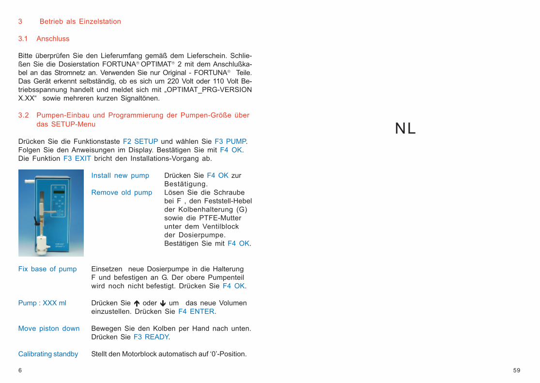
Install new pump Drücken Sie F4 OK zurBestätigung.
Remove old pump Lösen Sie die Schraubebei F , den Feststell-Hebelder Kolbenhalterung (G)sowie die PTFE-Mutterunter dem Ventilblockder Dosierpumpe.Bestätigen Sie mit F4 OK.
Fix base of pump Einsetzen neue Dosierpumpe in die HalterungF und befestigen an G. Der obere Pumpenteilwird noch nicht befestigt. Drücken Sie F4 OK.
Pump : XXX ml Drücken Sie oder um das neue Volumeneinzustellen. Drücken Sie F4 ENTER.
Move piston down Bewegen Sie den Kolben per Hand nach unten.Drücken Sie F3 READY.
Calibrating standby Stellt den Motorblock automatisch auf ‘0’-Position.
59
NL
7
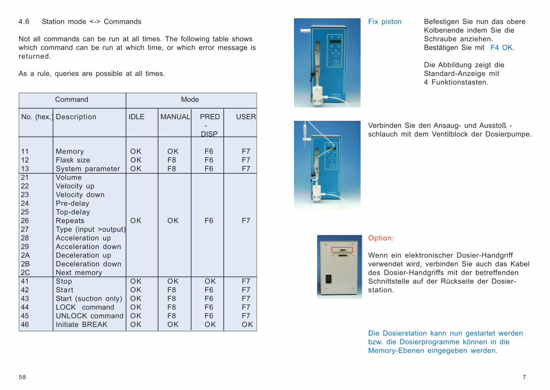
Fix piston Befestigen Sie nun das obereKolbenende indem Sie dieSchraube anziehen.Bestätigen Sie mit F4 OK.
Die Abbildung zeigt dieStandard-Anzeige mit4 Funktionstasten.
Verbinden Sie den Ansaug- und Ausstoß -schlauch mit dem Ventilblock der Dosierpumpe.
Option:
Wenn ein elektronischer Dosier-Handgriffverwendet wird, verbinden Sie auch das Kabeldes Dosier-Handgriffs mit der betreffendenSchnittstelle auf der Rückseite der Dosier-station.
Die Dosierstation kann nun gestartet werdenbzw. die Dosierprogramme können in dieMemory-Ebenen eingegeben werden.
58
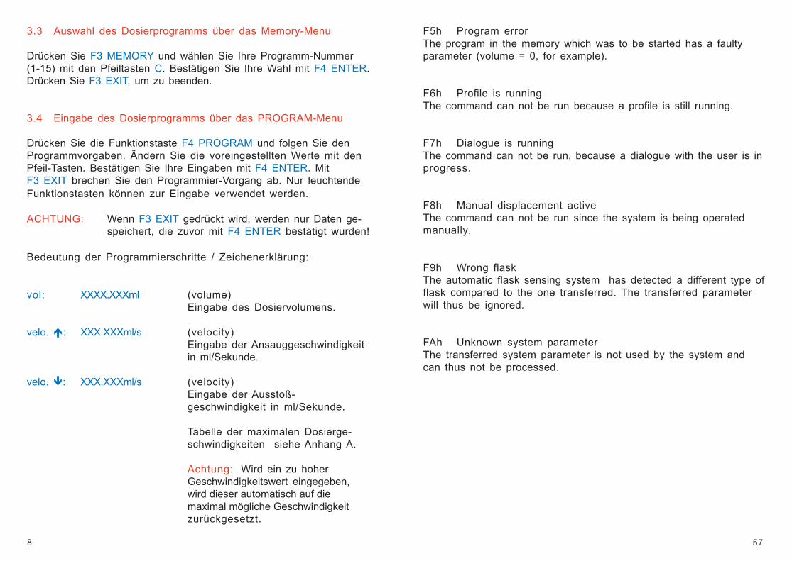
4.6 Station mode <-> Commands
Not all commands can be run at all times. The following table showswhich command can be run at which time, or which error message isreturned.
As a rule, queries are possible at all times.
Command Mode
No. (hex.) Description IDLE MANUAL PRED USER-
DISP
11 Memory OK OK F6 F7 12 Flask size OK F8 F6 F7 13 System parameter OK F8 F6 F7 21 Volume 22 Velocity up 23 Velocity down 24 Pre-delay 25 Top-delay 26 Repeats OK OK F6 F7 27 Type (input >output) 28 Acceleration up 29 Acceleration down 2A Deceleration up 2B Deceleration down 2C Next memory 41 Stop OK OK OK F7 42 Start OK F8 F6 F7 43 Start (suction only) OK F8 F6 F7 44 LOCK command OK F8 F6 F7 45 UNLOCK command OK F8 F6 F7 46 Initiate BREAK OK OK OK OK
8
3.3 Auswahl des Dosierprogramms über das Memory-Menu
Drücken Sie F3 MEMORY und wählen Sie Ihre Programm-Nummer(1-15) mit den Pfeiltasten C. Bestätigen Sie Ihre Wahl mit F4 ENTER.Drücken Sie F3 EXIT, um zu beenden.
3.4 Eingabe des Dosierprogramms über das PROGRAM-Menu
Drücken Sie die Funktionstaste F4 PROGRAM und folgen Sie denProgrammvorgaben. Ändern Sie die voreingestellten Werte mit denPfeil-Tasten. Bestätigen Sie Ihre Eingaben mit F4 ENTER. MitF3 EXIT brechen Sie den Programmier-Vorgang ab. Nur leuchtendeFunktionstasten können zur Eingabe verwendet werden.
ACHTUNG: Wenn F3 EXIT gedrückt wird, werden nur Daten ge-speichert, die zuvor mit F4 ENTER bestätigt wurden!
Bedeutung der Programmierschritte / Zeichenerklärung:
vol: XXXX.XXXml (volume)Eingabe des Dosiervolumens.
velo. : XXX.XXXml/s (velocity)Eingabe der Ansauggeschwindigkeitin ml/Sekunde.
velo. : XXX.XXXml/s (velocity)Eingabe der Ausstoß-geschwindigkeit in ml/Sekunde.
Tabelle der maximalen Dosierge-schwindigkeiten siehe Anhang A.
Achtung: Wird ein zu hoherGeschwindigkeitswert eingegeben,wird dieser automatisch auf diemaximal mögliche Geschwindigkeitzurückgesetzt.
57
F5h Program errorThe program in the memory which was to be started has a faultyparameter (volume = 0, for example).
F6h Profile is runningThe command can not be run because a profile is still running.
F7h Dialogue is runningThe command can not be run, because a dialogue with the user is inprogress.
F8h Manual displacement activeThe command can not be run since the system is being operatedmanually.
F9h Wrong flaskThe automatic flask sensing system has detected a different type offlask compared to the one transferred. The transferred parameterwill thus be ignored.
FAh Unknown system parameterThe transferred system parameter is not used by the system andcan thus not be processed.
9
predelay: XXXX s Bei einer Wiederholung: Eingabe derVerweilzeit zwischen START-Befehlund 1. Dosierung.Bei mehreren Wiederholungen: Ein-gabe der Verweilzeit zwischenSTART-Befehl und 1. Dosierung undallen weiteren Dosierungen.
topdelay: XXXX s Eingabe der Verweilzeit des Kolbensin oberster Position.(Diese Funktion ist nützlich bei derDosierung hochviskoser Flüssigkei-ten, damit die Ventilkugel gut schlie-ßen kann.)
repeat: XXXXX x Eingabe der Wiederholungen.ACHTUNG: Keine ‘0’-Eingabe.
typ: Input = Output Ansaugvolumen (vol) ist gleich demDosiervolumen.
Input > Output Wenn die Pumpe leer ist, bzw. wennnicht genug Flüssigkeit für den näch-sten Dosiervorgang in der Pumpe ist,saugt die Pumpe immer das Nenn-volumen an. Das dosierte Volumenbezieht sich auf das eingegebeneVolumen (vol).Verändern Sie die Werte durch die
Taste.
acceler. : XXX (Acceleration)Eingabe eines Wertes zwischen0 (keine Anfahrtsrampe) und 800(langsame Anfahrt), um einGeschwindigkeitsprofil (ramp) zuschaffen, wenn der Ansaug-vorgang startet.
56
54h Dispensed volume
Query: 54hReply: 54h, xx
xx: Dispensed quantity, format 8 digit BCD, unit µl. The transferredvalue corresponds to the last value for the volume as indicated bythe LCD display. Since for the output the last (not indicated) digit isrounded off, the transmitted value will be too high by 0.5 µl.
55h Conversion factor Steps / ml
Query: 55hReply: 55h, xx
xx: Conversion factor, BCD, 8 digits
56h Maximum value ml/s
Query: 56hReply: 56h, xx
xx: Highest possible value for ml/s + 1
4.5 Messages / Replies to Commands
The messages / replies are sent by the station in response to suchframes which do not request a return value, or which have errors.
F1h Command understoodAll is OK, command has been understood and run.
F2h Command unknownReply F2h, xx - command xx is undefined.F3h Parameter is not permissibleThe transmitted parameter is out of range.
F4h Syntax errorThe frame is either too short or too long (missing characters, or toomany).
10
acceler. : XXX (Acceleration)Eingabe eines Wertes zwischen 0(keine Anfahrtsrampe) und 800(langsame Anfahrt), um einGeschwindigkeitsprofil (ramp) zuschaffen, wenn der Dosiervorgangstartet.
deceler. : XXX (Deceleration)Eingabe eines Wertes zwischen0 (keine Anfahrtsrampe) und 800(langsame Anfahrt), um einGeschwindigkeitsprofil (ramp) fürdas Ende des Ansaugvorgangs zuschaffen.
deceler. : XXX (Deceleration)Eingabe eines Wertes zwischen 0(keine Anfahrtsrampe) und 800(langsame Anfahrt), um einGeschwindigkeitsprofil (ramp) fürdas Ende des Dosiervorgangs zuschaffen.
next memory: XX Eingabe des nächsten Memorys, umeine Dosierkette (Verbindungs-aufgabe) zu schaffen.Wenn ‘0’ eingegeben wird, wird dasProgramm nicht verkettet, d.h. es istbeendet.
(Ende der Programmierung.)
3.5 Starten des gewählten Dosierprogramms über das START-Menu
Drücken Sie die Funktions-Taste F1 START, um ein ausgewähltesDosierprogramm zu starten; drücken Sie im Notfall die Motor-STOP-Taste, um den Dosiervorgang zu unterbrechen. Nach Beendigung desDosiervorgangs befindet sich die Dosierstation wieder im Eingabe-Modus: die Funktionstasten F1 - F4 können gedrückt werden.
55
4.4 Status Queries
Query of internal station status
51h Station mode
Query: 51hReply: 51h, xx
xx: 0 = IDLE, standstill, idle1 = MANUAL, manual displacement2 = DISP, dispensing, station ejects3 = TOPD, station is in the top delay state4 = ASPI, Station is sucking in5 = PRED = Station is in the pre-delay state6 = USER, dialogue with the user is running
52h Number of repeats
Query: 52hReply: 52h, value
Value: Number of repeats not yet completed, 8 digit BCD value (4 bytes)
53h End of last profile
Query: 53hReply: 53h, xx
xx: 0 = NORM, profile terminated normally1 = STOP, termination by operating the EMERGENCY STOP
push-button2 = COMM, end by STOP command3 = PROG, end because of program error255 = RUN, profile is still running
11
4 Betrieb als Doppelstation
Um die Dosierstation FORTUNA OPTIMAT
2 als Doppelstation
nutzen zu können, muß sie mit einer Schnittstelle ausgestattet undeinem entsprechenden Kabel verbunden werden (Option).
4.1 Definition des Status der Dosierstation
Die erste Dosierstation FORTUNA OPTIMAT
2 muss als CONTROLLER
definiert werden, die zweite Dosierstation als SLAVE. Alle weiterenDosierstationen müssen auch als SLAVE definiert werden.
Das Display zeigt 4 Funktionen: F1 EXECUTE, F2 SETUP,F3 MEM+PRG und F4 EDIT. Drücken Sie F2 SETUP für den Controller/Slave Status. Danach drücken Sie F2 STATUS.
status: contr. (Slave/Unique)Ändern Sie den Wert in dem Sie den aufleuchtenden Ein-gabeschlüssel drücken und mit F4 ENTER bestätigen.
4.2 Pumpen-Einbau und Programmierung der Pumpen-Größeüber das Setup-Menu.
Entsprechende Informationen entnehmen Sie bitte den Seiten 6 ff.
4.3 Auswahl des Dosierprogramms aus dem Memory-Menu
Drücken Sie F3 MEM+PRG und folgen Sie dem Programm, ändernSie die Werte in dem Sie die aufleuchtenden Funktionstastendrücken und mit F4 ENTER bestätigen.
sta: XX (Station) Eingabe der Nummer der jeweiligen Dosier-station. (Der Controller muss immer Nr. 0 sein, alleweiteren Slaves werden mit 01-99 numeriert.)
mem: XX Wählen Sie Ihre Programmnummer (1-15).
Um das Programmieren zu beenden, drücken Sie F3 EXIT.Achtung: Wenn F3 ENTER gedrückt wird, ist es möglich, dass
die Programmierung nicht vollständig ist.
54
44h LOCK Command
Command: 44hReply: F1h or F6h or F7h or F8h
Sets (if successful) the slave to the LOCKed state. In this state thestation can not initiate a manual displacement or a user dialogue.The station can only be controlled via the interface. This commandshould be sent ahead of complex operations via the interface. AnOPTIMAT controller sends the command before processing a codelist.
45h UNLOCK Command
Command: 45hReply: F1h
Cancels the LOCKed state of the slave. An OPTIMAT controllersends the command after processing a code list.
46h Initiate BREAK
Command: 46hReply: F1h
Causes the corresponding slave to activate its EXBREAK\ line. Thiscauses a BREAK in all connected slaves (including the one whichwas addressed). Therefore this command needs only to be sent toone slave in the network.
4Fh Test Command
Command: 47hReply: F1h
Causes all LEDs of the addressed slave to light up briefly; will not causeany operations or effects. This command may be used to check the linkwhen establishing a link between computer and OPTIMAT. Will possiblybe no longer implemented in subsequent software releases.
12
4.4 Auswahl des Memory-Programms
Um für den Controller ein Programm zu ändern oder neu zu pro-grammieren, folgen Sie bitte den auf den Seiten 8 ff beschriebenenProgrammierschritten. Um für die Dosiereinheiten >00 (Slaves) einProgramm zu ändern bzw. neu zu programmieren, folgen Sie zu-nächst dem Abschnitt 4.3 Memory Auswahl, um die Dosiereinheit miteiner Nummer zu versehen und gehen Sie danach ebenso vor, wie inden Seiten 8 ff beschrieben.
4.5 Inbetriebnahme des ausgewählten Dosierprogramms
Drücken Sie F1 EXECUTE, um das ausgewählte Dosierprogramm zustarten.Drücken Sie die Motor-STOP-Taste, um den Dosiervorgang zu been-den bzw. im Notfall. Nachdem der Dosiervorgang beendet wordenist, zeigt das Display den Startmodus, d.h. die Funktionstasten F1bis F4 können ausgewählt werden.
4.6 Systemeingabemodus zur Doppelstationprogrammierung(nur für Servicetechniker bzw. geschultes Personal)
Wurde die Dosierstation FORTUNA OPTIMAT 2 als Doppelstationbestellt, ist diese Programmierung nicht notwendig und wurde bereitsdurch den Hersteller erledigt.Wenn die Programmierung durch Drücken von F4 EDIT geändert wur-de, kann die Doppelstation-Programmierung gelöscht worden sein!
Bevor Sie den Systemeingabemodus öffnen, starten Sie bitte mit:11.1 Definition des Status der Dosierstation
Drücken Sie F4 EDIT, um in den System-Programmier-Modus zu gelan-gen. Wenn Sie noch einmal F4 EDIT drücken, geht der Cursor auf dieerste Programmierzeile (falls vorhanden). Durch Eingabe von F4ENTER können die eingegebenen Werte bestätigt bzw. durch Drückender aufleuchtenden Programmiertasten geändert werden. Drücken SieF3 QUIT, um das Menu zu schließen.Soll die Doppelstation wieder als 2 Einzelstationen genutzt werden,folgen Sie 11.1 und ändern Sie den Wert der Dosierstation ab in‘UNIQUE’ (Einzelstation).
53
Example: Slave 15 is to be set to a dispensing volume of 1234.56 ml.
Frame:8Fh, 56h, 34h, 12h, 00h, 0Dh
Frame end
Dispensing volume, 8 digits BCD,least significant digit first
Slave address, binary OR 128
4.3 Sequencing Commands
Starting / stopping of processes41h STOP
Command: 41hReply: F1h
Stops the current dispensing process42h START
Command: 42hReply: F1h or F5h or F6h or F7h or F8h
Starts the dispensing process in the current memory state.43h START (suction only)
Command: 43hReply: F1h or F5h or F6h or F7h or F8h
Starts the dispensing process in the current memory state; suctiononly, the dispensing process is cancelled after the top delay haselapsed.
13
5 Fehlerbehebung - mögliche Störungen und einzuleitende AktionenStörung: Die Dosierstation läßt sich nicht einschalten.Aktion: Gerät auf Transportschäden und korrekten
Anschluß überprüfen. Sicherung prüfen. Wennkein Schaden erkennbar ist bzw. alle Kabelkorrekt angeschlossen sind, kontaktieren Siebitte den technischen Service.
Störung: Die Dosier-Pumpe dosiert zuviel oder zuwenig.Aktion: Pumpen-Installation überprüfen. Dosier-Pro-
gramm überprüfen. Anschluß-Schläuche aufDichtigkeit überprüfen. Dosier-Pumpe auf ein-wandfreie Funktion testen.
Störung: Die Dosierstation startet nicht.Aktion: Dosierprogramm überprüfen. Vermeiden Sie
Null-Eingaben. Gerät ausschalten und nach 5Minuten Wartezeit wieder einschalten. Bei Aus-fall des Gerätes techn. Service kontaktieren.
Störung: Die Dosierstation verzählt sich bzw. arbeitetnicht korrekt.
Aktion: Unterbrechen Sie das Programm über die NOT-STOP-Taste. Drücken Sie die Funktionstaste F2SETUP und wählen Sie F3 PUMP. Folgen Sie denAnweisungen am Display und bestätigen Sie mitF4 OK. Bauen Sie die Pumpe nicht aus. DieFunktion F3 EXIT bricht den Installations-Vor-gang ab. Nach erfolgter Neu-Installationkalibriert sich die Dosierstation selbständig.
6 TitrationEin bestimmtes Volumen kann innerhalb einer definiertenZeit kontinuierlich in Schritten titriert werden.
7 Programm-ErhaltungDurch Einbau von Programm-Speichern bleiben alle eingestellten Werte auchin abgeschaltetem Zustand und bei Stromausfall erhalten. Es ist jedoch rat-sam, bei Nicht-Inbetriebnahme von mehreren Wochen oder nach Netzstö-rungen, die programmierten Werte zu überprüfen.
52
21h Set/query volumeValue: Volume µl - from 0 to 9999999
22h Set/query velocityValue: Velocity in 1/100 ml/s - from 0 to 9999
23h Set/query velocity downValue: Velocity in 1/100 ml/s - from 0 to 9999
24h Set/query pre-delayValue: Pre-delay in s - from 0 to 9999
25h Set/query top delayValue: Top delay in s - from 0 to 9999
26h Set/query repeatValue: Number of repeats - from 0 to 9999
27h Set/query I/O typeValue: Input = Output = 00 00 00 00hInput > Output = 00 00 00 01h
28h Set/query acceleration upValue: Acceleration - from 0 to 999
29h Set/query acceleration downValue: Acceleration - from 0 to 999
2Ah Set/query deceleration upValue: Deceleration - from 0 to 999
2Bh Set/query deceleration downValue: Deceleration - from 0 to 999
2Ch Set/query next memoryValue: Next memory - from 0 to 15
14
8 a) Wartung/Pflege
Die Dosierstation FORTUNA OPTIMAT 2 ist durch weitgehend geschlos-sene Bauweise vor Verunreinigungen im Inneren geschützt. Alle verwende-ten mechanischen Teile sind wartungsfrei. Um jedoch eine dauerhafte Funk-tion zu gewährleisten, empfehlen wir eine regelmäßige technische Eigen-Kontrolle oder Überprüfung durch den Hersteller alle 2 Jahre.
8 b) Sterilisieren der OPTIMAT Dosierpumpen
Ausbau der Dosierpumpen (siehe auch Bedienungsanl. S. 6)Lösen Sie die Schraube der oberen Pumpen-Halterung, den Feststellhebelder unteren Pumpenhalterung sowie die PTFE-Mutter unter dem Ventilblockder Dosierpumpe. Entnehmen Sie die Dosierpumpe.
Demontage der Dosierpumpe: Nun ziehen Sie den Dosierkolben langsamaus dem Dosierzylinder heraus.
Sterilisation: Die zerlegte Dosierpumpe kann nun bei maximal +121°(+248°F)/1 bar sterilisiert werden.
Abkühlung: Nach der Sterilisation sollte die zerlegte Dosierpumpe bei Zim-mertemperatur langsam (mindestens 1 Stunde) abkühlen.
Montage der Dosierpumpen: Nach dem Abkühlen können Sie den Dosier-kolben wieder in den Dosierzylinder einführen.
Einbau der Dosierpumpen : Bitte folgen Sie beim Einbau der Dosierpumpendem Abschnitt 3.2 der OPTIMAT® Bedienungsanleitung (Seite 6+7).
9 Gewährleistung
Für die Dosierstation FORTUNA OPTIMAT
2 leisten wir eine Garantie
von 2 Jahren unter Ausschluss von Schadenersatz, Wandlung oder sons-tigen Ansprüchen. Die Dosierstation FORTUNA
OPTIMAT
2 ist war-
tungsfrei und dadurch extrem zuverlässig. Sollte sich dennoch eine Stö-rung bemerkbar machen, behält sich der Hersteller vor, fehlerhafte Teileinstandzusetzen oder auszutauschen. Wir haften nicht für Beschädigun-gen oder Störungen durch unsachgemäße Pflege oder Bedienung. An-sprüche sind bei der Liefer-Firma geltend zu machen. Durch eine Garan-tie-Reparatur tritt weder für die ersetzten Teile noch für das Gerät eineVerlängerung der Garantiezeit ein. Die Garantie erlischt, wenn an dem Ge-rät Reparaturen durch nicht autorisierte Personen vorgenommen werden.
51
To date, the following system parameters have been defined:
10: Sound signal during delay phasesoff = 0, on = 1, default : 1
80: Signal lead for the solenoid valvesrange: 0 ... 200, default: 0
81: Speed when driven manuallyrange: 0 ... 30, default: 20
90: CAN identifierrange: 0 ... 255, default 230
91: CAN bus timing 1range: 0 ... 255, default: 65
91: CAN bus timing 2range: 0 ... 255, default: 28
4.2 Memory Related Commands / Queries
Manipulation / analysis of the currently set memory.
All dialogue with 2x commands is run as follows:
Query: 2xhReply: 2xh, value
Set: 2xh, valueReply: F1h
Value: Parameter value - from/to, see individual commands
All values are transmitted by 8 digit BCD numbers through 4 bytes(given in the diagram only as ‘value’). The value is transmitted withthe least significant digits first. Here the reply of an error-free dia-logue is stated as the reply. For replies in the case of errors, seenext chapter.
15
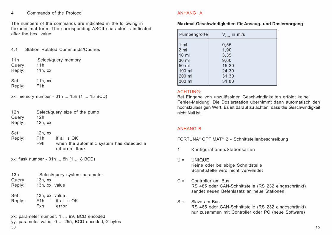
ANHANG A
Maximal-Geschwindigkeiten für Ansaug- und Dosiervorgang
Pumpengröße Vmax in ml/s
1 ml 0,55 2 ml 1,90 10 ml 3,35 30 ml 9,60 50 ml 15,20 100 ml 24,30 200 ml 31,30 300 ml 31,80
ACHTUNG:Bei Eingabe von unzulässigen Geschwindigkeiten erfolgt keineFehler-Meldung. Die Dosierstation übernimmt dann automatisch denhöchstzulässigen Wert. Es ist darauf zu achten, dass die Geschwindigkeitnicht Null ist.
ANHANG B
FORTUNA OPTIMAT 2 - Schnittstellenbeschreibung
1 Konfigurationen/Stationsarten
U = UNIQUEKeine oder beliebige SchnittstelleSchnittstelle wird nicht verwendet
C = Controller am BusRS 485 oder CAN-Schnittstelle (RS 232 eingeschränkt)sendet neuen Befehlssatz an neue Stationen
S = Slave am BusRS 485 oder CAN-Schnittstelle (RS 232 eingeschränkt)nur zusammen mit Controller oder PC (neue Software)
50
4 Commands of the Protocol
The numbers of the commands are indicated in the following inhexadecimal form. The corresponding ASCII character is indicatedafter the hex. value.
4.1 Station Related Commands/Queries
11h Select/query memoryQuery: 11hReply: 11h, xx
Set: 11h, xxReply: F1h
xx: memory number - 01h ... 15h (1 ... 15 BCD)
12h Select/query size of the pumpQuery: 12hReply: 12h, xx
Set: 12h, xxReply: F1h if all is OK
F9h when the automatic system has detected adifferent flask
xx: flask number - 01h ... 8h (1 ... 8 BCD)
13h Select/query system parameterQuery: 13h, xxReply: 13h, xx, value
Set: 13h, xx, valueReply: F1h if all is OK
Fxh error
xx: parameter number, 1 ... 99, BCD encodedyy: parameter value, 0 ... 255, BCD encoded, 2 bytes
16
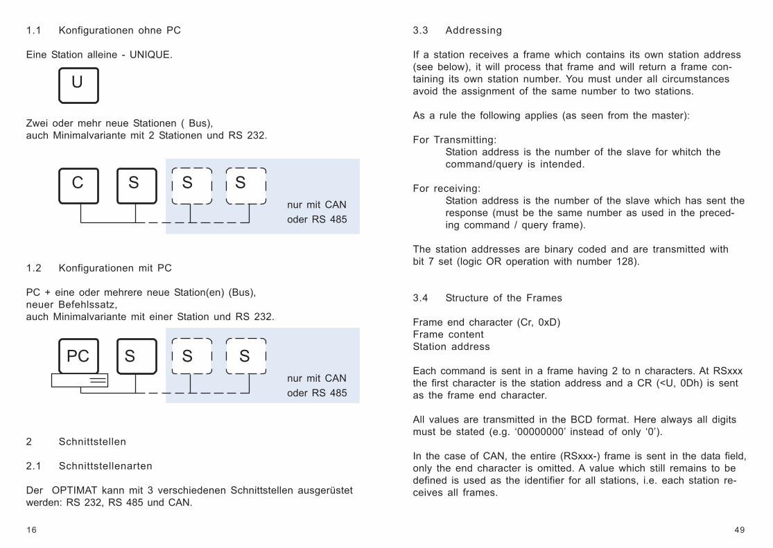
1.1 Konfigurationen ohne PC
Eine Station alleine - UNIQUE.
U
Zwei oder mehr neue Stationen ( Bus),auch Minimalvariante mit 2 Stationen und RS 232.
C S S Snur mit CANoder RS 485
1.2 Konfigurationen mit PC
PC + eine oder mehrere neue Station(en) (Bus),neuer Befehlssatz,auch Minimalvariante mit einer Station und RS 232.
PC S S Snur mit CANoder RS 485
2 Schnittstellen
2.1 Schnittstellenarten
Der OPTIMAT kann mit 3 verschiedenen Schnittstellen ausgerüstetwerden: RS 232, RS 485 und CAN.
49
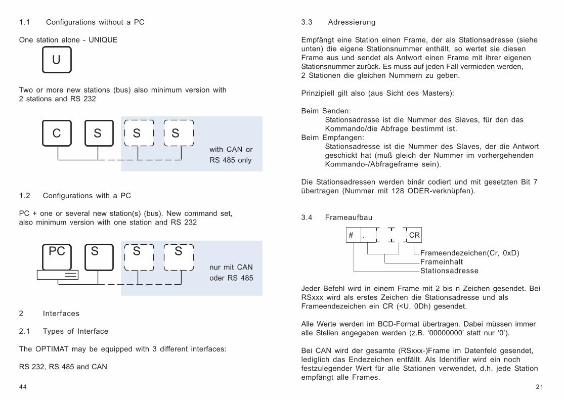
3.3 Addressing
If a station receives a frame which contains its own station address(see below), it will process that frame and will return a frame con-taining its own station number. You must under all circumstancesavoid the assignment of the same number to two stations.
As a rule the following applies (as seen from the master):
For Transmitting:Station address is the number of the slave for whitch thecommand/query is intended.
For receiving:Station address is the number of the slave which has sent theresponse (must be the same number as used in the preced-ing command / query frame).
The station addresses are binary coded and are transmitted withbit 7 set (logic OR operation with number 128).
3.4 Structure of the Frames
Frame end character (Cr, 0xD)Frame contentStation address
Each command is sent in a frame having 2 to n characters. At RSxxxthe first character is the station address and a CR (<U, 0Dh) is sentas the frame end character.
All values are transmitted in the BCD format. Here always all digitsmust be stated (e.g. ‘00000000’ instead of only ‘0’).
In the case of CAN, the entire (RSxxx-) frame is sent in the data field,only the end character is omitted. A value which still remains to bedefined is used as the identifier for all stations, i.e. each station re-ceives all frames.
17
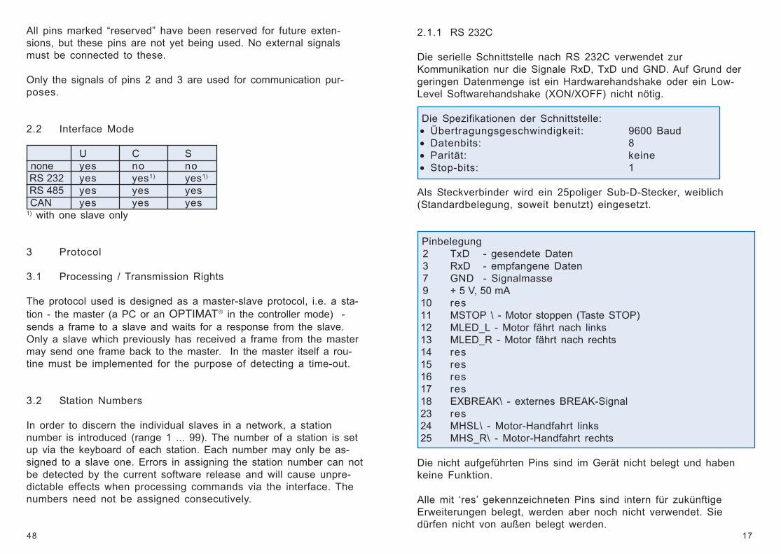
2.1.1 RS 232C
Die serielle Schnittstelle nach RS 232C verwendet zurKommunikation nur die Signale RxD, TxD und GND. Auf Grund dergeringen Datenmenge ist ein Hardwarehandshake oder ein Low-Level Softwarehandshake (XON/XOFF) nicht nötig.
Die Spezifikationen der Schnittstelle: • Übertragungsgeschwindigkeit: 9600 Baud • Datenbits: 8 • Parität: keine • Stop-bits: 1
Als Steckverbinder wird ein 25poliger Sub-D-Stecker, weiblich(Standardbelegung, soweit benutzt) eingesetzt.
Pinbelegung 2 TxD - gesendete Daten 3 RxD - empfangene Daten 7 GND - Signalmasse 9 + 5 V, 50 mA 10 res 11 MSTOP \ - Motor stoppen (Taste STOP) 12 MLED_L - Motor fährt nach links 13 MLED_R - Motor fährt nach rechts 14 res 15 res 16 res 17 res 18 EXBREAK\ - externes BREAK-Signal 23 res 24 MHSL\ - Motor-Handfahrt links 25 MHS_R\ - Motor-Handfahrt rechts
Die nicht aufgeführten Pins sind im Gerät nicht belegt und habenkeine Funktion.
Alle mit ‘res’ gekennzeichneten Pins sind intern für zukünftigeErweiterungen belegt, werden aber noch nicht verwendet. Siedürfen nicht von außen belegt werden.
48
All pins marked “reserved” have been reserved for future exten-sions, but these pins are not yet being used. No external signalsmust be connected to these.
Only the signals of pins 2 and 3 are used for communication pur-poses.
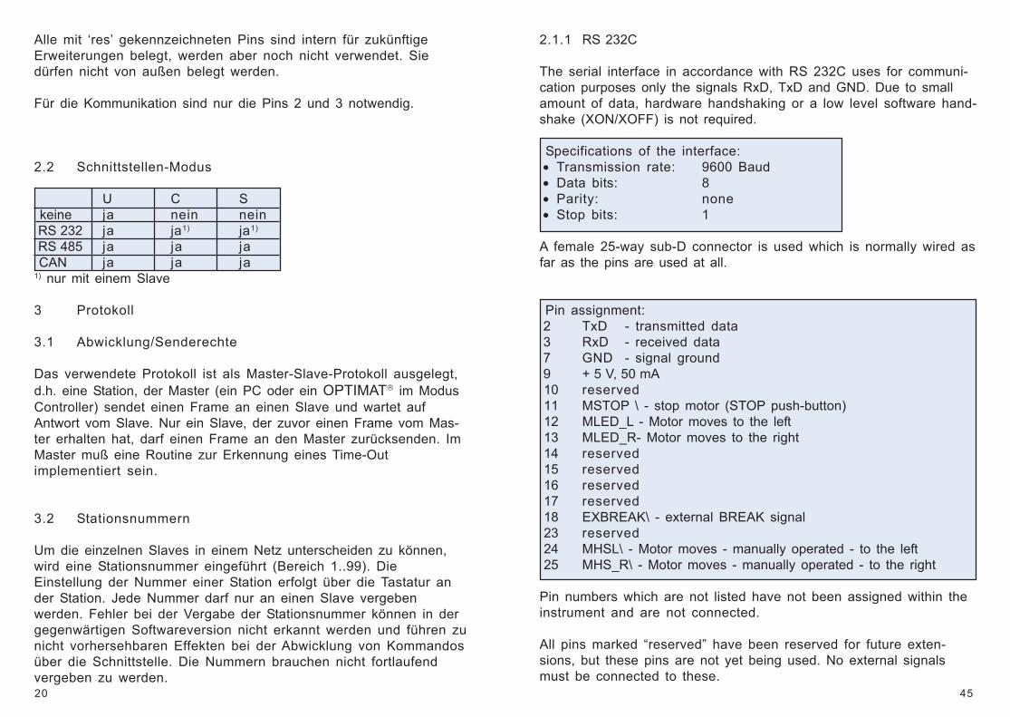
2.2 Interface Mode
U C S none yes no no RS 232 yes yes1) yes1)
RS 485 yes yes yes CAN yes yes yes1) with one slave only
3 Protocol
3.1 Processing / Transmission Rights
The protocol used is designed as a master-slave protocol, i.e. a sta-tion - the master (a PC or an OPTIMAT in the controller mode) -sends a frame to a slave and waits for a response from the slave.Only a slave which previously has received a frame from the mastermay send one frame back to the master. In the master itself a rou-tine must be implemented for the purpose of detecting a time-out.
3.2 Station Numbers
In order to discern the individual slaves in a network, a stationnumber is introduced (range 1 ... 99). The number of a station is setup via the keyboard of each station. Each number may only be as-signed to a slave one. Errors in assigning the station number can notbe detected by the current software release and will cause unpre-dictable effects when processing commands via the interface. Thenumbers need not be assigned consecutively.
18
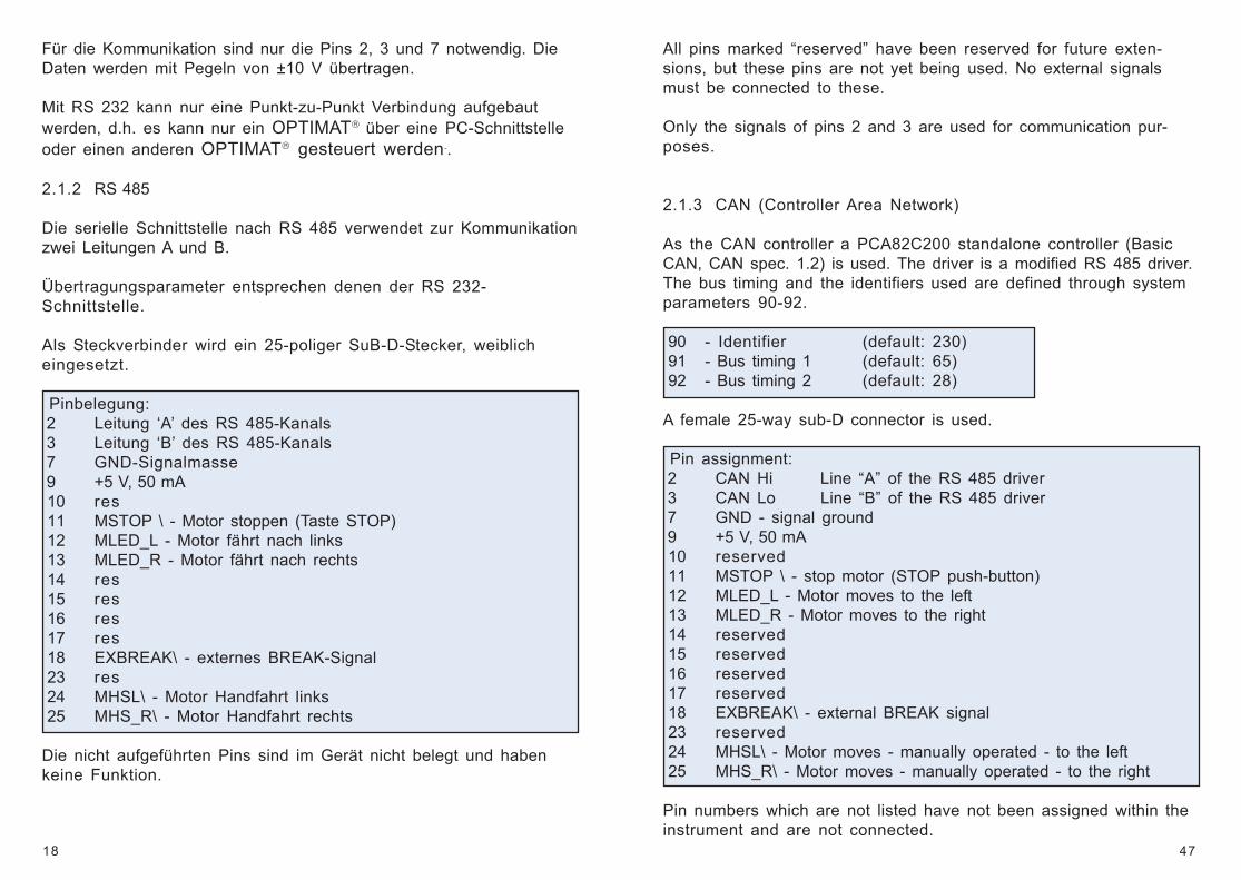
Für die Kommunikation sind nur die Pins 2, 3 und 7 notwendig. DieDaten werden mit Pegeln von ±10 V übertragen.
Mit RS 232 kann nur eine Punkt-zu-Punkt Verbindung aufgebautwerden, d.h. es kann nur ein OPTIMAT über eine PC-Schnittstelleoder einen anderen OPTIMAT gesteuert werden..
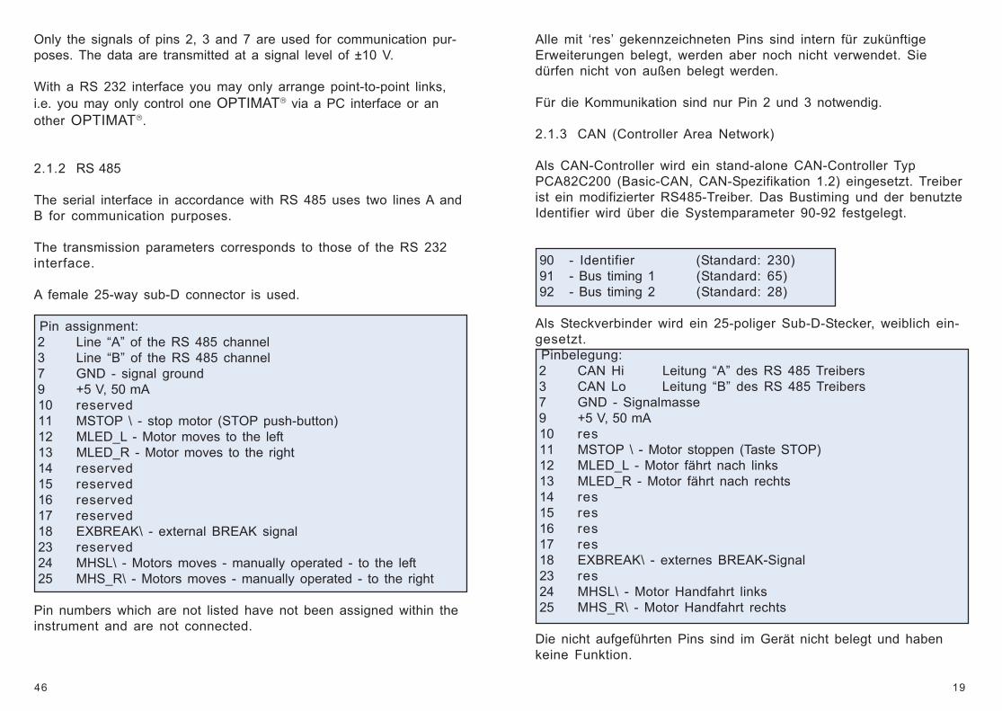
2.1.2 RS 485
Die serielle Schnittstelle nach RS 485 verwendet zur Kommunikationzwei Leitungen A und B.
Übertragungsparameter entsprechen denen der RS 232-Schnittstelle.
Als Steckverbinder wird ein 25-poliger SuB-D-Stecker, weiblicheingesetzt.
Pinbelegung: 2 Leitung ‘A’ des RS 485-Kanals 3 Leitung ‘B’ des RS 485-Kanals 7 GND-Signalmasse 9 +5 V, 50 mA 10 res 11 MSTOP \ - Motor stoppen (Taste STOP) 12 MLED_L - Motor fährt nach links 13 MLED_R - Motor fährt nach rechts 14 res 15 res 16 res 17 res 18 EXBREAK\ - externes BREAK-Signal 23 res 24 MHSL\ - Motor Handfahrt links 25 MHS_R\ - Motor Handfahrt rechts
Die nicht aufgeführten Pins sind im Gerät nicht belegt und habenkeine Funktion.
47
All pins marked “reserved” have been reserved for future exten-sions, but these pins are not yet being used. No external signalsmust be connected to these.
Only the signals of pins 2 and 3 are used for communication pur-poses.
2.1.3 CAN (Controller Area Network)
As the CAN controller a PCA82C200 standalone controller (BasicCAN, CAN spec. 1.2) is used. The driver is a modified RS 485 driver.The bus timing and the identifiers used are defined through systemparameters 90-92.
90 - Identifier (default: 230) 91 - Bus timing 1 (default: 65) 92 - Bus timing 2 (default: 28)
A female 25-way sub-D connector is used.
Pin assignment: 2 CAN Hi Line “A” of the RS 485 driver 3 CAN Lo Line “B” of the RS 485 driver 7 GND - signal ground 9 +5 V, 50 mA 10 reserved 11 MSTOP \ - stop motor (STOP push-button) 12 MLED_L - Motor moves to the left 13 MLED_R - Motor moves to the right 14 reserved 15 reserved 16 reserved 17 reserved 18 EXBREAK\ - external BREAK signal 23 reserved 24 MHSL\ - Motor moves - manually operated - to the left 25 MHS_R\ - Motor moves - manually operated - to the right
Pin numbers which are not listed have not been assigned within theinstrument and are not connected.
19
Alle mit ‘res’ gekennzeichneten Pins sind intern für zukünftigeErweiterungen belegt, werden aber noch nicht verwendet. Siedürfen nicht von außen belegt werden.
Für die Kommunikation sind nur Pin 2 und 3 notwendig.
2.1.3 CAN (Controller Area Network)
Als CAN-Controller wird ein stand-alone CAN-Controller TypPCA82C200 (Basic-CAN, CAN-Spezifikation 1.2) eingesetzt. Treiberist ein modifizierter RS485-Treiber. Das Bustiming und der benutzteIdentifier wird über die Systemparameter 90-92 festgelegt.
90 - Identifier (Standard: 230) 91 - Bus timing 1 (Standard: 65) 92 - Bus timing 2 (Standard: 28)
Als Steckverbinder wird ein 25-poliger Sub-D-Stecker, weiblich ein-gesetzt. Pinbelegung: 2 CAN Hi Leitung “A” des RS 485 Treibers 3 CAN Lo Leitung “B” des RS 485 Treibers 7 GND - Signalmasse 9 +5 V, 50 mA 10 res 11 MSTOP \ - Motor stoppen (Taste STOP) 12 MLED_L - Motor fährt nach links 13 MLED_R - Motor fährt nach rechts 14 res 15 res 16 res 17 res 18 EXBREAK\ - externes BREAK-Signal 23 res 24 MHSL\ - Motor Handfahrt links 25 MHS_R\ - Motor Handfahrt rechts
Die nicht aufgeführten Pins sind im Gerät nicht belegt und habenkeine Funktion.
46
Only the signals of pins 2, 3 and 7 are used for communication pur-poses. The data are transmitted at a signal level of ±10 V.
With a RS 232 interface you may only arrange point-to-point links,i.e. you may only control one OPTIMAT via a PC interface or another OPTIMAT.
2.1.2 RS 485
The serial interface in accordance with RS 485 uses two lines A andB for communication purposes.
The transmission parameters corresponds to those of the RS 232interface.
A female 25-way sub-D connector is used.
Pin assignment: 2 Line “A” of the RS 485 channel 3 Line “B” of the RS 485 channel 7 GND - signal ground 9 +5 V, 50 mA 10 reserved 11 MSTOP \ - stop motor (STOP push-button) 12 MLED_L - Motor moves to the left 13 MLED_R - Motor moves to the right 14 reserved 15 reserved 16 reserved 17 reserved 18 EXBREAK\ - external BREAK signal 23 reserved 24 MHSL\ - Motors moves - manually operated - to the left 25 MHS_R\ - Motors moves - manually operated - to the right
Pin numbers which are not listed have not been assigned within theinstrument and are not connected.
20
Alle mit ‘res’ gekennzeichneten Pins sind intern für zukünftigeErweiterungen belegt, werden aber noch nicht verwendet. Siedürfen nicht von außen belegt werden.
Für die Kommunikation sind nur die Pins 2 und 3 notwendig.
2.2 Schnittstellen-Modus
U C S keine ja nein nein RS 232 ja ja1) ja1)
RS 485 ja ja ja CAN ja ja ja1) nur mit einem Slave
3 Protokoll
3.1 Abwicklung/Senderechte
Das verwendete Protokoll ist als Master-Slave-Protokoll ausgelegt,d.h. eine Station, der Master (ein PC oder ein OPTIMAT im ModusController) sendet einen Frame an einen Slave und wartet aufAntwort vom Slave. Nur ein Slave, der zuvor einen Frame vom Mas-ter erhalten hat, darf einen Frame an den Master zurücksenden. ImMaster muß eine Routine zur Erkennung eines Time-Outimplementiert sein.
3.2 Stationsnummern
Um die einzelnen Slaves in einem Netz unterscheiden zu können,wird eine Stationsnummer eingeführt (Bereich 1..99). DieEinstellung der Nummer einer Station erfolgt über die Tastatur ander Station. Jede Nummer darf nur an einen Slave vergebenwerden. Fehler bei der Vergabe der Stationsnummer können in dergegenwärtigen Softwareversion nicht erkannt werden und führen zunicht vorhersehbaren Effekten bei der Abwicklung von Kommandosüber die Schnittstelle. Die Nummern brauchen nicht fortlaufendvergeben zu werden.
45
2.1.1 RS 232C
The serial interface in accordance with RS 232C uses for communi-cation purposes only the signals RxD, TxD and GND. Due to smallamount of data, hardware handshaking or a low level software hand-shake (XON/XOFF) is not required.
Specifications of the interface: • Transmission rate: 9600 Baud • Data bits: 8 • Parity: none • Stop bits: 1
A female 25-way sub-D connector is used which is normally wired asfar as the pins are used at all.
Pin assignment: 2 TxD - transmitted data 3 RxD - received data 7 GND - signal ground 9 + 5 V, 50 mA 10 reserved 11 MSTOP \ - stop motor (STOP push-button) 12 MLED_L - Motor moves to the left 13 MLED_R- Motor moves to the right 14 reserved 15 reserved 16 reserved 17 reserved 18 EXBREAK\ - external BREAK signal 23 reserved 24 MHSL\ - Motor moves - manually operated - to the left 25 MHS_R\ - Motor moves - manually operated - to the right
Pin numbers which are not listed have not been assigned within theinstrument and are not connected.
All pins marked “reserved” have been reserved for future exten-sions, but these pins are not yet being used. No external signalsmust be connected to these.
21
3.3 Adressierung
Empfängt eine Station einen Frame, der als Stationsadresse (sieheunten) die eigene Stationsnummer enthält, so wertet sie diesenFrame aus und sendet als Antwort einen Frame mit ihrer eigenenStationsnummer zurück. Es muss auf jeden Fall vermieden werden,2 Stationen die gleichen Nummern zu geben.
Prinzipiell gilt also (aus Sicht des Masters):
Beim Senden:Stationsadresse ist die Nummer des Slaves, für den dasKommando/die Abfrage bestimmt ist.
Beim Empfangen:Stationsadresse ist die Nummer des Slaves, der die Antwortgeschickt hat (muß gleich der Nummer im vorhergehendenKommando-/Abfrageframe sein).
Die Stationsadressen werden binär codiert und mit gesetzten Bit 7übertragen (Nummer mit 128 ODER-verknüpfen).
3.4 Frameaufbau
# . CR
Frameendezeichen(Cr, 0xD)FrameinhaltStationsadresse
Jeder Befehl wird in einem Frame mit 2 bis n Zeichen gesendet. BeiRSxxx wird als erstes Zeichen die Stationsadresse und alsFrameendezeichen ein CR (<U, 0Dh) gesendet.
Alle Werte werden im BCD-Format übertragen. Dabei müssen immeralle Stellen angegeben werden (z.B. ‘00000000’ statt nur ‘0’).
Bei CAN wird der gesamte (RSxxx-)Frame im Datenfeld gesendet,lediglich das Endezeichen entfällt. Als Identifier wird ein nochfestzulegender Wert für alle Stationen verwendet, d.h. jede Stationempfängt alle Frames.
44
1.1 Configurations without a PC
One station alone - UNIQUE
U
Two or more new stations (bus) also minimum version with2 stations and RS 232
C S S Swith CAN orRS 485 only
1.2 Configurations with a PC
PC + one or several new station(s) (bus). New command set,also minimum version with one station and RS 232
PC S S Snur mit CANoder RS 485
2 Interfaces
2.1 Types of Interface
The OPTIMAT may be equipped with 3 different interfaces:
RS 232, RS 485 and CAN
22
4 Befehle des Protokolls
Die Befehlsnummern sind im folgenden hexadezimal dargestellt.Hinter den Befehlsnummern ist das entsprechende ASCII-Zeichendargestellt.
4.1 Stationsbezogene Befehle/Abfragen
11h Memory auswählen/abfragenAbfrage: 11hAntwort: 11h, xx
Setzen: 11h, xxAntwort: F1h
xx: Memorynummer - 01h ... 15h (1 ... 15 BCD)
12h Pumpengröße auswählen/abfragenAbfrage: 12hAntwort: 12h, xx
Setzen: 12h, xxAntwort: F1h wenn alles ok ist
F9h wenn die Automatik einen anderenKolben erkannt hat
xx: Kolbennummer - 01h ... 8h (1 ... 8 BCD)
13h Systemparameter setzen/abfragenAbfrage: 13h, xxAntwort: 13h, xx, wert
Setzen: 13h, xx, wertAntwort: F1h wenn alles ok ist
Fxh Fehler
xx: Parameternummer, 1 ... 99, BCD-codiertyy: Parameterwert, 0 ... 255, BCD - codiert, 2 Bytes
43
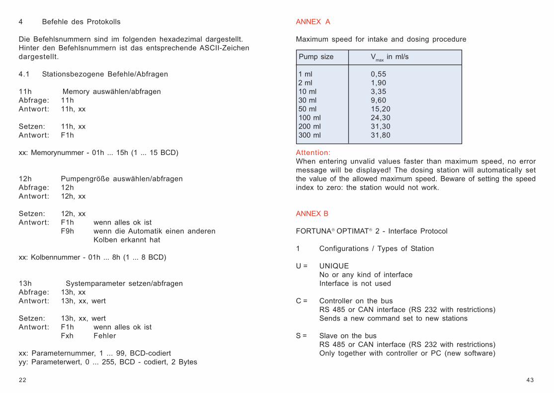
ANNEX A
Maximum speed for intake and dosing procedure
Pump size Vmax in ml/s
1 ml 0,55 2 ml 1,90 10 ml 3,35 30 ml 9,60 50 ml 15,20 100 ml 24,30 200 ml 31,30 300 ml 31,80
Attention:When entering unvalid values faster than maximum speed, no errormessage will be displayed! The dosing station will automatically setthe value of the allowed maximum speed. Beware of setting the speedindex to zero: the station would not work.
ANNEX B
FORTUNA OPTIMAT 2 - Interface Protocol
1 Configurations / Types of Station
U = UNIQUENo or any kind of interfaceInterface is not used
C = Controller on the busRS 485 or CAN interface (RS 232 with restrictions)Sends a new command set to new stations
S = Slave on the busRS 485 or CAN interface (RS 232 with restrictions)Only together with controller or PC (new software)
23
Definiert sind bisher folgende Systemparameter:
10: Tonsignal in Delay-Phasenaus = 0, ein = 1, Default : 1
80: Signalvorlauf für MagnetventileBereich: 0 ... 200, Default: 0
81: Geschwindigkeit für HandfahrtBereich: 0 ... 30, Default: 20
90: CAN-IdentifierBereich: 0 ... 255, Default: 230
91: CAN-Bus timing 1Bereich: 0 ... 255, Default: 65
92: CAN-Bus timing 2Bereich: 0 ... 255, Default: 28
4.2 Memorybezogene Befehle/Abfragen
Manipulieren / analysieren immer den aktuell gesetzten Memory.
Alle Dialoge mit 2 x Befehlen laufen nach folgendem Muster:
Abfrage: 2xhAntwort: 2xh, wert
Setzen: 2xh, wertAntwort: F1h
wert: Parameterwert - von/bis siehe einzelne Befehle
Alle Werte werden als 8-stellige BCD-Zahl in 4 Bytes übertragen (imDiagramm nur mit ‘wert’ angegeben). Übertragen wird der Wert mitden niederwertigsten Stellen zuerst. Als Antwort ist hier die Antwortim fehlerfreien Dialog genannt. Antworten bei Fehlern siehenächstes Kapitel.
42
8 a) Maintenance
By its mainly closed construction the dosing station FORTUNA OPTIMAT 2is protected from contaminations. All mechanical parts used are nearlymaintenance-free. In order to guarantee a long-lasting functioning, werecommend a regular technical control either by yourself or by themanufacturer in a 2 years period.
8 b) Sterilization
Removal of dosing pumps (see manual page 34):Remove the screw of the upper pump holder and remove the pump from thelower pump holder by opening the PTFE screw of the pump.
Dismantling of dosing pumps: Pull the dosing piston out of the dosingcylinder.
Sterilization: The dismantled dosing pump can be sterilized at +121° C(+248°F)/1 bar (max.).
Cooling: After the sterilization the dismantled dosing pump should be allowedto cool down very slowly at room temperatur (minimum 1 hour).
Assembly of dosing pumps: After cooling the dosing piston may be insertedinto the dosing cylinder.
Installation of dosing pumps: Please follow the instructions on page 6 and 7.
9 Warranty
The manufacturer guarantees each dosing station for a period of 2 yearsexcluding all claims for damage, conversion or other claims. The dosingstation FORTUNA OPTIMAT 2 is maintenance-free and extremely reliable.However, if any trouble arises, the manufacturer reserves the right to repairor exchange faulty parts. The manufacturer cannot be held responsible fordamages or troubles caused by improper handling or maintenance. All claimsshould be reported to the supplier. The warranty period shall not be extendedas a result of repair under warranty, neither for the replacement parts nor forthe dosing station itself. The warranty shall become null and void, if repairshave been carried out by unauthorized persons.
24
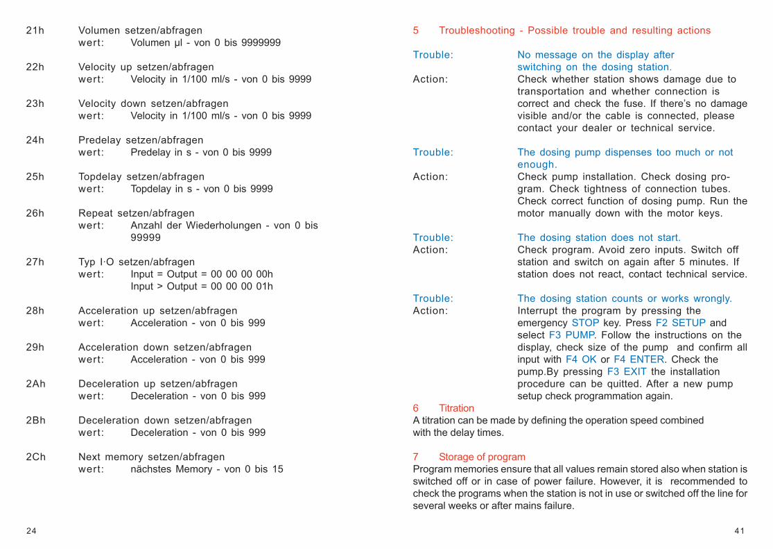
21h Volumen setzen/abfragenwert: Volumen µl - von 0 bis 9999999
22h Velocity up setzen/abfragenwert: Velocity in 1/100 ml/s - von 0 bis 9999
23h Velocity down setzen/abfragenwert: Velocity in 1/100 ml/s - von 0 bis 9999
24h Predelay setzen/abfragenwert: Predelay in s - von 0 bis 9999
25h Topdelay setzen/abfragenwert: Topdelay in s - von 0 bis 9999
26h Repeat setzen/abfragenwert: Anzahl der Wiederholungen - von 0 bis
99999
27h Typ I·O setzen/abfragenwert: Input = Output = 00 00 00 00h
Input > Output = 00 00 00 01h
28h Acceleration up setzen/abfragenwert: Acceleration - von 0 bis 999
29h Acceleration down setzen/abfragenwert: Acceleration - von 0 bis 999
2Ah Deceleration up setzen/abfragenwert: Deceleration - von 0 bis 999
2Bh Deceleration down setzen/abfragenwert: Deceleration - von 0 bis 999
2Ch Next memory setzen/abfragenwert: nächstes Memory - von 0 bis 15
41
5 Troubleshooting - Possible trouble and resulting actions
Trouble: No message on the display afterswitching on the dosing station.
Action: Check whether station shows damage due totransportation and whether connection iscorrect and check the fuse. If there’s no damagevisible and/or the cable is connected, pleasecontact your dealer or technical service.
Trouble: The dosing pump dispenses too much or notenough.
Action: Check pump installation. Check dosing pro-gram. Check tightness of connection tubes.Check correct function of dosing pump. Run themotor manually down with the motor keys.
Trouble: The dosing station does not start.Action: Check program. Avoid zero inputs. Switch off
station and switch on again after 5 minutes. Ifstation does not react, contact technical service.
Trouble: The dosing station counts or works wrongly.Action: Interrupt the program by pressing the
emergency STOP key. Press F2 SETUP andselect F3 PUMP. Follow the instructions on thedisplay, check size of the pump and confirm allinput with F4 OK or F4 ENTER. Check thepump.By pressing F3 EXIT the installationprocedure can be quitted. After a new pumpsetup check programmation again.
6 TitrationA titration can be made by defining the operation speed combinedwith the delay times.
7 Storage of programProgram memories ensure that all values remain stored also when station isswitched off or in case of power failure. However, it is recommended tocheck the programs when the station is not in use or switched off the line forseveral weeks or after mains failure.
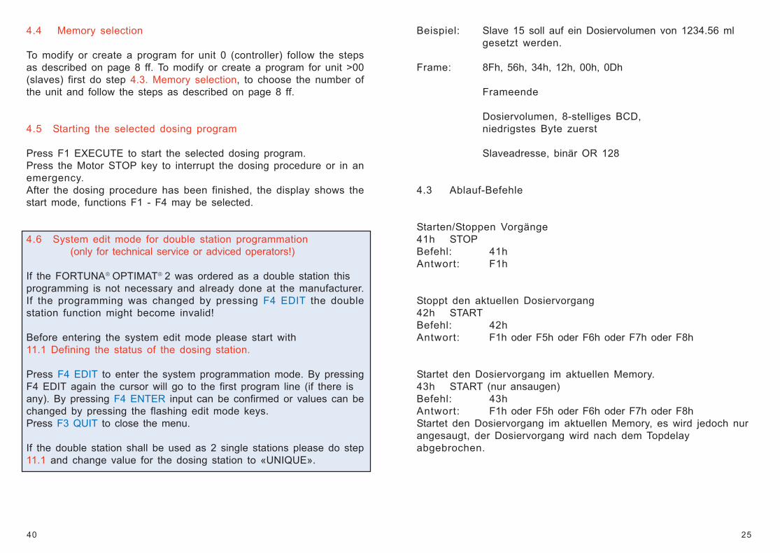
25
Beispiel: Slave 15 soll auf ein Dosiervolumen von 1234.56 mlgesetzt werden.
Frame: 8Fh, 56h, 34h, 12h, 00h, 0Dh
Frameende
Dosiervolumen, 8-stelliges BCD,niedrigstes Byte zuerst
Slaveadresse, binär OR 128
4.3 Ablauf-Befehle
Starten/Stoppen Vorgänge41h STOPBefehl: 41hAntwort: F1h
Stoppt den aktuellen Dosiervorgang42h STARTBefehl: 42hAntwort: F1h oder F5h oder F6h oder F7h oder F8h
Startet den Dosiervorgang im aktuellen Memory.43h START (nur ansaugen)Befehl: 43hAntwort: F1h oder F5h oder F6h oder F7h oder F8hStartet den Dosiervorgang im aktuellen Memory, es wird jedoch nurangesaugt, der Dosiervorgang wird nach dem Topdelayabgebrochen.
40
4.4 Memory selection
To modify or create a program for unit 0 (controller) follow the stepsas described on page 8 ff. To modify or create a program for unit >00(slaves) first do step 4.3. Memory selection, to choose the number ofthe unit and follow the steps as described on page 8 ff.
4.5 Starting the selected dosing program
Press F1 EXECUTE to start the selected dosing program.Press the Motor STOP key to interrupt the dosing procedure or in anemergency.After the dosing procedure has been finished, the display shows thestart mode, functions F1 - F4 may be selected.
4.6 System edit mode for double station programmation (only for technical service or adviced operators!)
If the FORTUNA OPTIMAT 2 was ordered as a double station thisprogramming is not necessary and already done at the manufacturer.If the programming was changed by pressing F4 EDIT the doublestation function might become invalid!
Before entering the system edit mode please start with11.1 Defining the status of the dosing station.
Press F4 EDIT to enter the system programmation mode. By pressingF4 EDIT again the cursor will go to the first program line (if there isany). By pressing F4 ENTER input can be confirmed or values can bechanged by pressing the flashing edit mode keys.Press F3 QUIT to close the menu.
If the double station shall be used as 2 single stations please do step11.1 and change value for the dosing station to «UNIQUE».
26
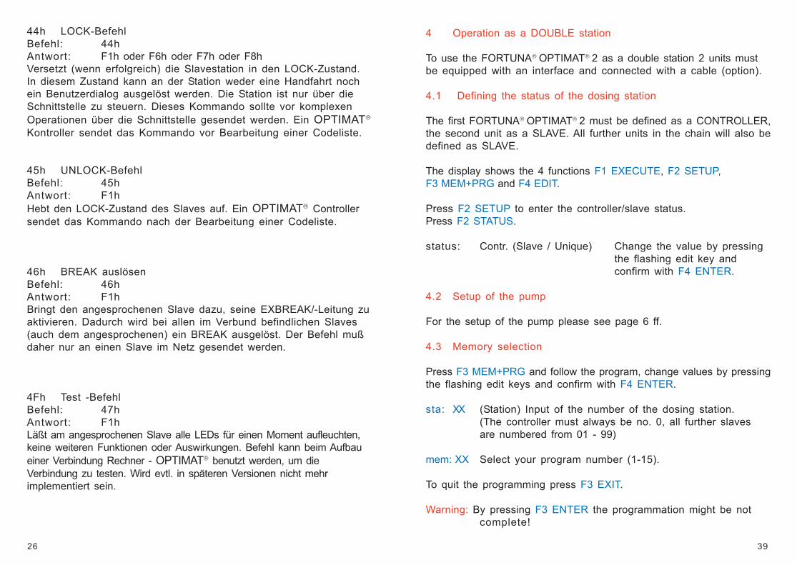
44h LOCK-BefehlBefehl: 44hAntwort: F1h oder F6h oder F7h oder F8hVersetzt (wenn erfolgreich) die Slavestation in den LOCK-Zustand.In diesem Zustand kann an der Station weder eine Handfahrt nochein Benutzerdialog ausgelöst werden. Die Station ist nur über dieSchnittstelle zu steuern. Dieses Kommando sollte vor komplexenOperationen über die Schnittstelle gesendet werden. Ein OPTIMAT
Kontroller sendet das Kommando vor Bearbeitung einer Codeliste.
45h UNLOCK-BefehlBefehl: 45hAntwort: F1hHebt den LOCK-Zustand des Slaves auf. Ein OPTIMAT Controllersendet das Kommando nach der Bearbeitung einer Codeliste.
46h BREAK auslösenBefehl: 46hAntwort: F1hBringt den angesprochenen Slave dazu, seine EXBREAK/-Leitung zuaktivieren. Dadurch wird bei allen im Verbund befindlichen Slaves(auch dem angesprochenen) ein BREAK ausgelöst. Der Befehl mußdaher nur an einen Slave im Netz gesendet werden.
4Fh Test -BefehlBefehl: 47hAntwort: F1hLäßt am angesprochenen Slave alle LEDs für einen Moment aufleuchten,keine weiteren Funktionen oder Auswirkungen. Befehl kann beim Aufbaueiner Verbindung Rechner - OPTIMAT benutzt werden, um dieVerbindung zu testen. Wird evtl. in späteren Versionen nicht mehrimplementiert sein.
39
4 Operation as a DOUBLE station
To use the FORTUNA OPTIMAT 2 as a double station 2 units mustbe equipped with an interface and connected with a cable (option).
4.1 Defining the status of the dosing station
The first FORTUNA OPTIMAT 2 must be defined as a CONTROLLER,the second unit as a SLAVE. All further units in the chain will also bedefined as SLAVE.
The display shows the 4 functions F1 EXECUTE, F2 SETUP,F3 MEM+PRG and F4 EDIT.
Press F2 SETUP to enter the controller/slave status.Press F2 STATUS.
status: Contr. (Slave / Unique) Change the value by pressingthe flashing edit key andconfirm with F4 ENTER.
4.2 Setup of the pump
For the setup of the pump please see page 6 ff.
4.3 Memory selection
Press F3 MEM+PRG and follow the program, change values by pressingthe flashing edit keys and confirm with F4 ENTER.
sta: XX (Station) Input of the number of the dosing station.(The controller must always be no. 0, all further slavesare numbered from 01 - 99)
mem: XX Select your program number (1-15).
To quit the programming press F3 EXIT.
Warning: By pressing F3 ENTER the programmation might be notcomplete!
27
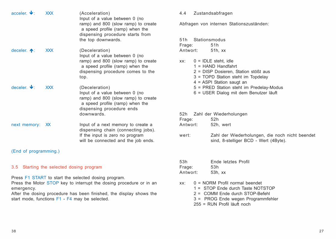
4.4 Zustandsabfragen
Abfragen von internen Stationszuständen:
51h StationsmodusFrage: 51hAntwort: 51h, xx
xx: 0 = IDLE steht, idle1 = HAND Handfahrt2 = DISP Dosieren, Station stößt aus3 = TOPD Station steht im Topdelay4 = ASPI Station saugt an5 = PRED Station steht im Predelay-Modus6 = USER Dialog mit dem Benutzer läuft
52h Zahl der WiederholungenFrage: 52hAntwort: 52h, wert
wert: Zahl der Wiederholungen, die noch nicht beendetsind, 8-stelliger BCD - Wert (4Byte).
53h Ende letztes ProfilFrage: 53hAntwort: 53h, xx
xx: 0 = NORM Profil normal beendet1 = STOP Ende durch Taste NOTSTOP2 = COMM Ende durch STOP-Befehl3 = PROG Ende wegen Programmfehler255 = RUN Profil läuft noch
38
acceler. : XXX (Acceleration)Input of a value between 0 (noramp) and 800 (slow ramp) to create a speed profile (ramp) when thedispensing procedure starts fromthe top downwards.
deceler. : XXX (Deceleration)Input of a value between 0 (noramp) and 800 (slow ramp) to create a speed profile (ramp) when thedispensing procedure comes to thetop.
deceler. : XXX (Deceleration)Input of a value between 0 (noramp) and 800 (slow ramp) to create a speed profile (ramp) when thedispensing procedure endsdownwards.
next memory: XX Input of a next memory to create adispensing chain (connecting jobs).If the input is zero no programwill be connected and the job ends.
(End of programming.)
3.5 Starting the selected dosing program
Press F1 START to start the selected dosing program.Press the Motor STOP key to interrupt the dosing procedure or in anemergency.After the dosing procedure has been finished, the display shows thestart mode, functions F1 - F4 may be selected.
28
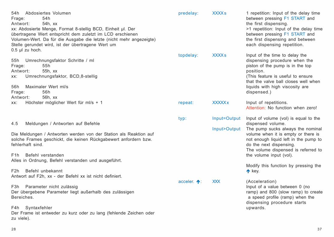
54h Abdosiertes VolumenFrage: 54hAntwort: 54h, xxxx: Abdosierte Menge, Format 8-stellig BCD, Einheit µl. Derübertragene Wert entspricht dem zuletzt im LCD erschienenVolumen-Wert. Da für die Ausgabe die letzte (nicht mehr angezeigte)Stelle gerundet wird, ist der übertragene Wert um0.5 µl zu hoch.
55h Umrechnungsfaktor Schritte / mlFrage: 55hAntwort: 55h, xxxx: Umrechnungsfaktor, BCD,8-stellig
56h Maximaler Wert ml/sFrage: 56hAntwort: 56h, xxxx: Höchster möglicher Wert für ml/s + 1
4.5 Meldungen / Antworten auf Befehle
Die Meldungen / Antworten werden von der Station als Reaktion aufsolche Frames geschickt, die keinen Rückgabewert anfordern bzw.fehlerhaft sind.
F1h Befehl verstandenAlles in Ordnung, Befehl verstanden und ausgeführt.
F2h Befehl unbekanntAntwort auf F2h, xx - der Befehl xx ist nicht definiert.
F3h Parameter nicht zulässigDer übergebene Parameter liegt außerhalb des zulässigenBereiches.
F4h SyntaxfehlerDer Frame ist entweder zu kurz oder zu lang (fehlende Zeichen oderzu viele).
37
predelay: XXXX s 1 repetition: Input of the delay timebetween pressing F1 START andthe first dispensing.>1 repetition: Input of the delay timebetween pressing F1 START andthe first dispensing and betweeneach dispensing repetition.
topdelay: XXXX s Input of the time to delay thedispensing procedure when thepiston of the pump is in the topposition.(This feature is useful to ensurethat the valve ball closes well whenliquids with high viscosity aredispensed.)
repeat: XXXXX x Input of repetitions.Attention: No function when zero!
typ: Input=Output Input of volume (vol) is equal to thedispensed volume.
Input>Output The pump sucks always the nominalvolume when it is empty or there isnot enough liquid left in the pump todo the next dispensing.The volume dispensed is referred tothe volume input (vol).
Modify this function by pressing the key.
acceler. : XXX (Acceleration)Input of a value between 0 (noramp) and 800 (slow ramp) to create a speed profile (ramp) when thedispensing procedure startsupwards.
29
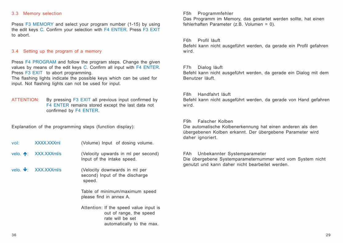
F5h ProgrammfehlerDas Programm im Memory, das gestartet werden sollte, hat einenfehlerhaften Parameter (z.B. Volumen = 0).
F6h Profil läuftBefehl kann nicht ausgeführt werden, da gerade ein Profil gefahrenwird.
F7h Dialog läuftBefehl kann nicht ausgeführt werden, da gerade ein Dialog mit demBenutzer läuft.
F8h Handfahrt läuftBefehl kann nicht ausgeführt werden, da gerade von Hand gefahrenwird.
F9h Falscher KolbenDie automatische Kolbenerkennung hat einen anderen als denübergebenen Kolben erkannt. Der übergebene Parameter wirddaher ignoriert.
FAh Unbekannter SystemparameterDie übergebene Systemparameternummer wird vom System nichtgenutzt und kann daher nicht bearbeitet werden.
36
3.3 Memory selection
Press F3 MEMORY and select your program number (1-15) by usingthe edit keys C. Confirm your selection with F4 ENTER. Press F3 EXITto abort.
3.4 Setting up the program of a memory
Press F4 PROGRAM and follow the program steps. Change the givenvalues by means of the edit keys C. Confirm all input with F4 ENTER.Press F3 EXIT to abort programming.The flashing lights indicate the possible keys which can be used forinput. Not flashing lights can not be used for input.
ATTENTION: By pressing F3 EXIT all previous input confirmed byF4 ENTER remains stored except the last data notconfirmed by F4 ENTER.
Explanation of the programming steps (function display):
vol: XXXX.XXXml (Volume) Input of dosing volume.
velo. : XXX.XXXml/s (Velocity upwards in ml per second)Input of the intake speed.
velo. : XXX.XXXml/s (Velocity downwards in ml persecond) Input of the discharge speed.
Table of minimum/maximum speedplease find in annex A.
Attention: If the speed value input isout of range, the speedrate will be setautomatically to the max.
30
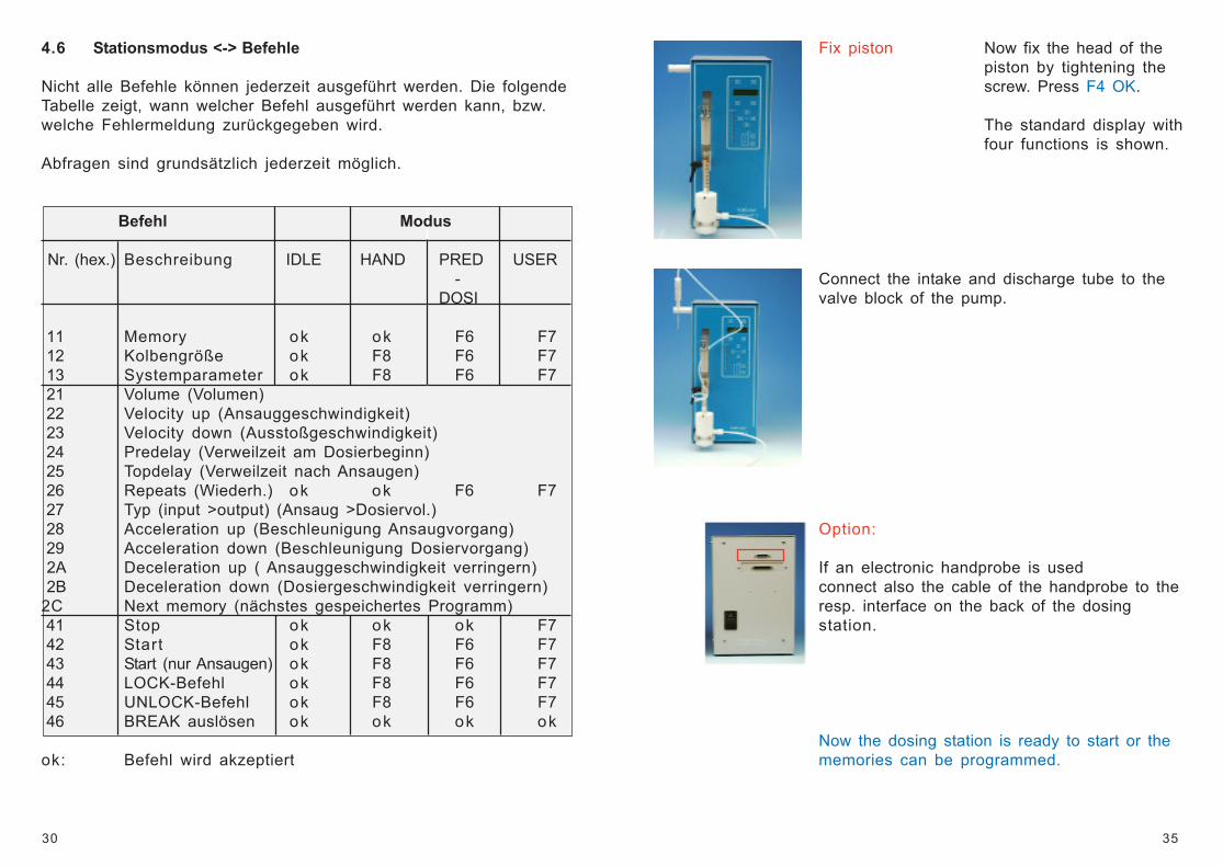
4.6 Stationsmodus <-> Befehle
Nicht alle Befehle können jederzeit ausgeführt werden. Die folgendeTabelle zeigt, wann welcher Befehl ausgeführt werden kann, bzw.welche Fehlermeldung zurückgegeben wird.
Abfragen sind grundsätzlich jederzeit möglich.
Befehl Modus
Nr. (hex.) Beschreibung IDLE HAND PRED USER-
DOSI
11 Memory ok ok F6 F7 12 Kolbengröße ok F8 F6 F7 13 Systemparameter ok F8 F6 F7 21 Volume (Volumen) 22 Velocity up (Ansauggeschwindigkeit) 23 Velocity down (Ausstoßgeschwindigkeit) 24 Predelay (Verweilzeit am Dosierbeginn) 25 Topdelay (Verweilzeit nach Ansaugen) 26 Repeats (Wiederh.) ok ok F6 F7 27 Typ (input >output) (Ansaug >Dosiervol.) 28 Acceleration up (Beschleunigung Ansaugvorgang) 29 Acceleration down (Beschleunigung Dosiervorgang) 2A Deceleration up ( Ansauggeschwindigkeit verringern) 2B Deceleration down (Dosiergeschwindigkeit verringern)2C Next memory (nächstes gespeichertes Programm) 41 Stop ok ok ok F7 42 Start ok F8 F6 F7 43 Start (nur Ansaugen) ok F8 F6 F7 44 LOCK-Befehl ok F8 F6 F7 45 UNLOCK-Befehl ok F8 F6 F7 46 BREAK auslösen ok ok ok ok
ok: Befehl wird akzeptiert
35
Fix piston Now fix the head of thepiston by tightening thescrew. Press F4 OK.
The standard display withfour functions is shown.
Connect the intake and discharge tube to thevalve block of the pump.
Option:
If an electronic handprobe is usedconnect also the cable of the handprobe to theresp. interface on the back of the dosingstation.
Now the dosing station is ready to start or thememories can be programmed.
31
GB
34
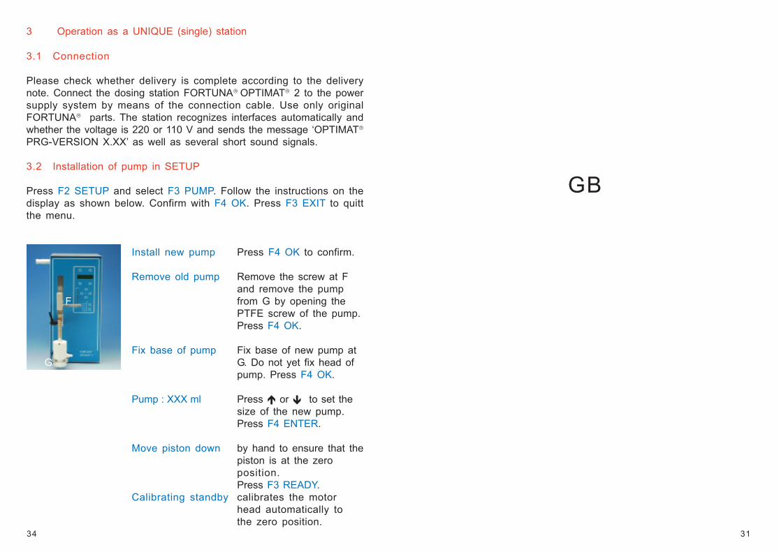
3 Operation as a UNIQUE (single) station
3.1 Connection
Please check whether delivery is complete according to the deliverynote. Connect the dosing station FORTUNA OPTIMAT 2 to the powersupply system by means of the connection cable. Use only originalFORTUNA parts. The station recognizes interfaces automatically andwhether the voltage is 220 or 110 V and sends the message ‘OPTIMAT
PRG-VERSION X.XX’ as well as several short sound signals.
3.2 Installation of pump in SETUP
Press F2 SETUP and select F3 PUMP. Follow the instructions on thedisplay as shown below. Confirm with F4 OK. Press F3 EXIT to quittthe menu.
Install new pump Press F4 OK to confirm.
Remove old pump Remove the screw at Fand remove the pump
F from G by opening thePTFE screw of the pump.Press F4 OK.
Fix base of pump Fix base of new pump at G G. Do not yet fix head of
pump. Press F4 OK.
Pump : XXX ml Press or to set thesize of the new pump.Press F4 ENTER.
Move piston down by hand to ensure that thepiston is at the zeroposition.Press F3 READY.
Calibrating standby calibrates the motorhead automatically tothe zero position.
32
Preface
We thank you for the purchase of the FORTUNA OPTIMAT dosingstation. You did a good choice. With more than 20 years of experiencein making dosing systems we guarantee a high standard of productquality and safety.
To guarantee quality and safety of the dosing station also for a longterm, a correct operating and maintenance is necessary.
Therefore please read this operating manual carefully before usingthe dosing station and take notice of the warning instructions as wellas the corresponding regulations.
The delivery contains: 1 FORTUNA OPTIMAT 2 dosing station withintegrated programming terminal.Please see our catalog for the options.
1 The world of FORTUNA OPTIMAT 2
150.000-2 FORTUNA OPTIMAT 2 COMFORTwith integrated programming terminal
150.000-3 FORTUNA OPTIMAT 2 COMFORT / Swith integrated programming terminal andconnection port RS 232 (standard),RS 485 or CAN
Optional:
150.000-10 Interface RS 232 (only for cat. no. 150.000-2) 150.000-20 Interface RS 485 (only for cat. no. 150.000-2) 150.000-30 Interface CAN (only for cat. no. 150.000-2)
The dosing station FORTUNA OPTIMAT 2 is suitable for one OPTIMAT
pump only (please see our catalog for accessories). The dosing station150.000-3 OPTIMAT 2 COMFORT / S can be networked with furtherdosing stations OPTIMAT 2 COMFORT / S or other hardware (e. g. printer,balance) via a cable (option).
33
STO
P
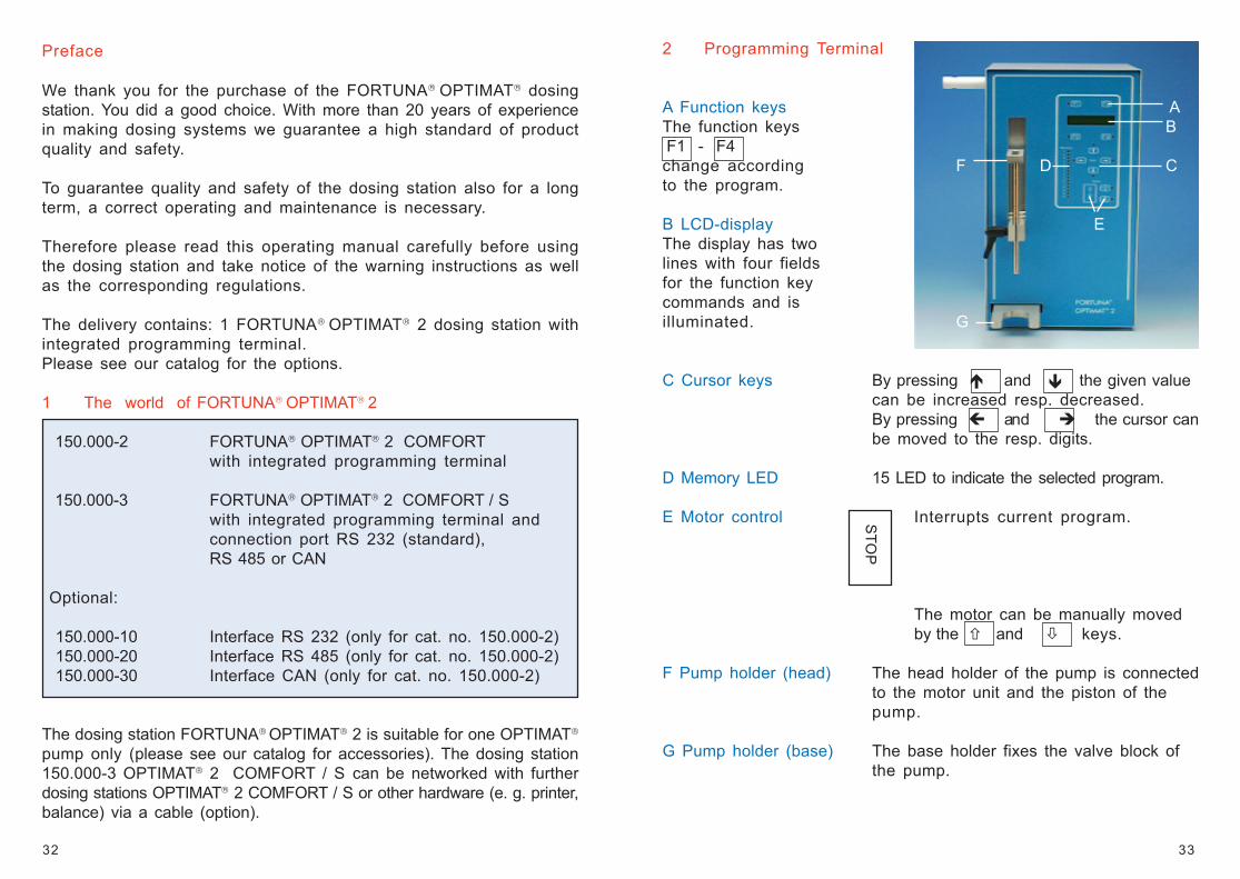
2 Programming Terminal
A Function keys AThe function keys B F1 - F4change according F D Cto the program.
B LCD-display EThe display has twolines with four fieldsfor the function keycommands and isilluminated. G
C Cursor keys By pressing and the given valuecan be increased resp. decreased.By pressing and the cursor canbe moved to the resp. digits.
D Memory LED 15 LED to indicate the selected program.
E Motor control Interrupts current program.
The motor can be manually movedby the and keys.
F Pump holder (head) The head holder of the pump is connectedto the motor unit and the piston of thepump.
G Pump holder (base) The base holder fixes the valve block ofthe pump.