Embed Size (px)
Citation preview
Scannable OfficeForm PublisherForm ReaderData Mapper
SO License and Notice Final.qxd 3/21/00 6:31 PM Page 1

Notice
Information in this manual is subject to change without notice and does not represent a commitment on thepart of AutoData Systems, a unit of Electro-Sensors, Inc. The software described in this document is fur-nished under a license agreement which states the terms for use of this product. No part of this publica-tion may be reproduced, transmitted, stored in a retrieval system, or translated into another language forany purpose, without the express written permission of AutoData Systems.
This manual is sold as is, without warranty of any kind, either express or implied, respecting the contentsof this manual, including but not limited to implied warranties for the manual’s quality, performance, mer-chantability, or fitness for any particular purpose. Neither AutoData Systems nor its dealers or distributorsshall be liable to the purchaser or any other person or entity with respect to any liability, loss or damagecaused or alleged to be caused directly or indirectly by this manual.
All AutoData Systems programs are protected by at least U.S. Patent Numbers 4,504,970; 4,541,115;4,550,431; 4,551,850; 5,473,707; 5,473,708; and other pending U.S. patents.
Copyright © 1993-2000 AutoData Systems, a unit of Electro-Sensors, Inc. All rights reserved.AutoData is a registered trademark and SmartMemory is a trademark of Electro-Sensors, Inc.Microsoft, Windows and Windows NT are registered trademarks of Microsoft Corporation.ISIS is a registered trademark of Pixel Translations, Inc.OCR technology manufactured under NewSoft America, Inc., license 105-55000.Other products and company names may be trademarks or registered trademarks of their respective com-panies.
AutoData Systems6111 Blue Circle DriveMinneapolis, MN 55343
Technical Support:
Phone: 952-945-2801FAX: 952-938-4693Email: [email protected]
Sales Department:
Phone: 952-938-4710FAX: 952-938-4693Email: [email protected]
Web Site URL:
www.autodata.com
SO License and Notice Final.qxd 3/21/00 6:31 PM Page 2

AUTODATA ® SYSTEMS SOFTWARE LICENSE
This software is protected by United States copyright law and International treaty provisions. Therefore, you may make archival copiesof this software for the sole purpose of backing-up the software and protecting your investment. You may use the software only on asingle CPU. This means you must license a copy of the software for each computer on which you wish to use the software.
You may not download or transmit the software electronically (either by direct connection or telecommunication transmission) from onecomputer to another for purposes other than back-up, or as instructed by AutoData. You may transfer all of your rights to use the soft-ware to another person, provided that you transfer to that person (or destroy) all of the software, disk(s), CD-ROM and documentationprovided in this package, together with all copies, tangible or intangible, including copies in RAM or installed on a drive, as well as allback-up copies. Once you transfer the software, it may only be used at the single location to which it is transferred, and only in accor-dance with the copyright laws and international treaty provisions. Except as stated in this paragraph, you may not otherwise transfer,rent, lease, sub-license, time-share, or lend the software, disk(s), CD-ROM or documentation. Your use of the software is limited toacts that are essential steps in the use of the software on your computer as described in the documentation. You may not otherwisemodify, alter, adapt, merge, decompile or reverse-engineer the software, and you may not remove or obscure AutoData Systemsand/or Electro-Sensors copyright or trademark notices.
LIMITED WARRANTY
AutoData Systems (“AutoData”), a unit of Electro-Sensors, Inc. (“Electro-Sensors”) warrants the physical disk(s), CD-ROM and/orphysical documentation enclosed herein to be free of defects in materials and workmanship for a period of sixty days from the pur-chase date. If AutoData receives notification within the warranty period of defects in materials or workmanship, and such notification isdetermined by AutoData to be correct, AutoData will replace the defective disk(s), CD-ROM or documentation. DO NOT RETURNANY PRODUCT UNTIL YOU HAVE CALLED THE AUTODATA TECHNICAL SUPPORT DEPARTMENT AND OBTAINED A RETURNAUTHORIZATION NUMBER.
AUTODATA SPECIFICALLY DISCLAIMS ALL OTHER WARRANTIES, EXPRESS OR IMPLIED INCLUDING, BUT NOT LIMITED TO,ANY IMPLIED WARRANTY OF MERCHANTABILITY OR FITNESS FOR A PARTICULAR PURPOSE. AUTODATA DOES NOT WAR-RANT OR GUARANTEE THAT THE AUTODATA SYSTEMS SOFTWARE WILL ACCURATELY IDENTIFY ALL CHARACTERS ORMARKS. YOU AGREE TO ASSUME ALL RISK AND LIABILITY, AND AGREE TO INDEMNIFY AND HOLD AUTODATA HARMLESSFROM, ALL CLAIMS, ACTIONS, DAMAGES, LIABILITY, COSTS AND EXPENSES RESULTING FROM THE FAILURE OF THEAUTODATA SYSTEMS SOFTWARE TO ACCURATELY IDENTIFY SUCH CHARACTERS OR MARKS.
Specifically, AutoData makes no representation or warranty that the software is fit for any particular purpose, and any implied warrantyof merchantability which cannot be disclaimed is limited to the sixty-day duration of the Limited Warranty covering the physical disk(s),CD-ROM and physical documentation only (and not the software) and is otherwise expressly and specifically disclaimed.
The entire and exclusive liability and remedy for breach of this Limited Warranty shall be limited to replacement of defective disk(s),CD-ROM or documentation and shall not include or extend to any claim for or right to recover any other damages, including but notlimited to, loss of profit, data or use of the software, or special, incidental or consequential damages or other similar claims, even ifAutoData has been specifically advised of the possibility of such damages.
This limited warranty gives you specific legal rights; you may have others which may vary from state to state. Some states do notallow the exclusion of incidental or consequential damages, or the limitation on how long an implied warranty lasts, so some of theabove may not apply to you.
GOVERNING LAW AND GENERAL PROVISIONS
This license shall be construed, interpreted, and governed by the laws of the State of Minnesota. If any provision of this license isfound void or unenforceable, it will not affect the validity of this license, which shall remain valid and enforceable according to its terms.If any remedy provided is determined to have failed of its essential purpose, all limitations of liability and exclusions of damages set forin the Limited Warranty shall remain in full force and effect. In no event will AutoData’s liability for any damages to you or any otherperson ever exceed the lower of suggested list price or actual price paid for the license to use the software, regardless of any form ofthe claim.
Printed in USA.
SO License and Notice Final.qxd 3/21/00 6:31 PM Page 3

SO License and Notice Final.qxd 3/21/00 6:31 PM Page 4

i
ContentsChapter 1 Introduction to AutoData Scannable Office 1
About AutoData Scannable Office 1About This Manual 2System Requirements for Scannable Office 3
Hardware Requirements 3Software Requirements 4Before You Start 4
Installing the Scannable Office Software Modules 4The AutoData Protection Key 5The Sample Forms 6
Chapter 2 Using AutoData Scannable Office 9
The Scannable Office Modules 9AutoData Form Publisher 10AutoData Form Reader 11AutoData Data Mapper 11AutoData Template Maker 12
Using Scannable Office: Four Scenarios 13Scenario 1: Form Publisher form creation, new database 14Scenario 2: Template Maker definition, new database 16Scenario 3: Form Publisher form creation, existing database 18Scenario 4: Template Maker definition, existing database 20
A Word About Scannable Office Files 22
Chapter 3 Designing Forms 23
Form Fields: Asking the Right Question 24Form Layout: Inviting Accurate Answers 24
Six Basic Field Types 25Proper Use of Serial Fields 28Page Length and Page Order Restrictions 29
Page Size Requirements 29Page Orientation 30Locator Marks 30
SO TOC Final.qxd 3/21/00 6:30 PM Page i
Using Non-Reproducible Blue Ink 31Creating Two-Sided Duplex Forms 31Printing Your Form 32Other Special Handling Tips 32
Chapter 4 Using AutoData Form Publisher 35
Starting Out 36Launching Form Publisher and Opening a New Form Document 36The Form Publisher Window 37Page Setup for New Forms 40Document Setup Considerations 41Opening Existing Files 44Saving Files 47
Defining Scannable Objects 47Overview 47Check Mark Fields 54Hand Print Fields 66Bar Code Fields 74OCR Fields 79Image Capture Fields 82Key Entry Fields 84Fine-Tuning Your Form: Grouping, Layering, and Positioning 86Grouping 86Layering 88Positioning 88Converting a Word Document to a Scannable Form 90
Publishing Your Form 91Prior to Publishing 91Publishing the Form 92Printing Reproduction Masters 94Printing Merged Field Forms 94
Chapter 5 Using AutoData Form Reader 97
Launching Form Reader 98The Form Reader Window 99
The Form Reader Toolbar 99Form Reader Menus 101
Processing Forms 104
ii Contents
SO TOC Final.qxd 3/21/00 6:30 PM Page ii
Overview 104Step 1: Specifying an Input Source 105Step 2: Setting Program Options 109Step 3: Scanning Your Forms 114Step 4: Processing and Verifying Your Scanned Data 122
Using the Image Viewer 133Image Viewer Toolbar 133Image Viewer Menus 134Using the Image Viewer 136
Chapter 6 Using AutoData Data Mapper 139
Starting Out 140Launching Data Mapper and Viewing Files 140The Data Mapper Toolbar 140Data Mapper Menus 141Understanding Data Relationships 143Anatomy of the Data Mapper Window 143
Creating the Map File: Understanding the Relationship Between a Form and Its Database 145
Step 1: Selecting the Form File 145Step 2: Selecting or Creating the Database to Store the Form’s Data 146Step 3: Matching Form Fields with Database Fields 149Step 4: Saving the Map File and Exiting Data Mapper 158
Management Tools 158The Association Manager 158
Chapter 7 Advanced Topics 165
Batch Scanning and Processing 165Scanner Processing Flow 168
Importing Images Scanned Outside of Form Reader 169Imported Images Processing Flow 171
Using PaperPort to Process Forms 172PaperPort Processing Flow 174
Using WinFax PRO to Process Forms 175Exporting to a Text File 180Merging Serialized Data to a Bar Code or OCR Field 181
Merging Serialized Data to a Bar Code 181Merging Serialized Data to an OCR Field 186
Contents iii
SO TOC Final.qxd 3/21/00 6:30 PM Page iii

Creating and Using 11"×17" Duplex Booklets 187Requirements needed to scan 11"×17" booklets: 187
Appendix A Network Installation 189
Appendix B Setting Up ISIS Scanners 193
Appendix C Setting up TWAIN Scanners 199
Appendix D AutoData Scannable Office Files 203
Understanding File Relationships 203Scannable Office File Types 203The Association Manager 204The Image Database 204The Map File 205
Appendix E AutoData SmartMemory Technical Description 207
Origin of Technology 207SmartMemory and Associative Recall 207The Power of SmartMemory 208SmartMemory Operational Diagram 208
Appendix F Hexadecimal Locators 211
Glossary 215
Index 223
iv Contents
SO TOC Final.qxd 3/21/00 6:30 PM Page iv
1
Chapter 1Introduction to AutoData ScannableOffice
Welcome to AutoData ® Scannable Office, AutoData’s innovative and automated datacollection solution for the desktop. The technology used in Scannable Office hasbeen refined over a ten-year period in programs aimed at a highly specialized andsophisticated market. The proliferation of affordable imaging scanners andcomputer-based fax programs now makes it possible for AutoData to make thisunion of software and technology available to a much wider audience. Only theimagination and creativity of the user limit the broad variety of applications for usewith Scannable Office.
About AutoData Scannable OfficeThe Scannable Office software consists of four distinct software modules:
n AutoData®
Form Publisher: This software module enables you to createscannable forms using AutoData Document Template macros that workseamlessly with Microsoft Word.
n AutoData®
Form Reader: This software module scans, processes and verifiesforms’ scannable elements read from images input either through a scanner,faxes received by WinFax PRO, or imported images. This module automaticallycreates a target database and stores captured data directly in an Access database,Excel spreadsheet or ODBC data source.
n AutoData® Data Mapper: This software module maps the scannable objects onany new or existing form to an existing Access, Excel or ODBC data source.
SO Chapter 1 final.qxd 3/21/00 6:15 PM Page 1
Data Mapper also registers forms in a database, and creates new databases witheasy-to-use Wizards. Data Mapper is a useful tool for advanced users.
n AutoData® Template Maker: This software module makes forms, created inother programs such as PageMaker or QuarkXPress, compatible with ScannableOffice. Template Maker helps you define objects on these forms and save thefield information so it can be read and interpreted correctly by the otherScannable Office program modules.
About This ManualThe first three modules—Form Publisher, Form Reader and Data Mapper—aredescribed in this manual. The fourth module, Template Maker, is discussed in aseparate manual, AutoData Template Maker, included with the Scannable Officesoftware.
The manual is organized in the following manner:
n Chapter 1: Introduction to AutoData Scannable Office provides generalinformation about the software and this manual. It also covers systemrequirements for Scannable Office and describes the software installationprocedure.
n Chapter 2: Using AutoData Scannable Office explains how the ScannableOffice modules interact. Several basic scenarios are provided to help youdetermine which software modules should be used in a given situation.
n Chapter 3: Designing Forms describes the design considerations necessary foryour forms to be processed with Scannable Office. This section helps youunderstand how Scannable Office uses different scannable object fields tocapture data, and explains the all-important relationship between your form andthe final data outcome you expect.
n Chapter 4: Using AutoData Form Publisher describes in detail how to use theAutoData Document Template macro within Microsoft Word to create a printedform. After reading this chapter, you will be familiar with the six differentscannable object fields that are used in scannable form design.
n Chapter 5: Using AutoData Form Reader walks you through the process ofscanning, processing and verifying the data on your scannable form. You willbecome familiar with how the data is stored directly in your database of choice.
If you want to createforms in another soft-ware package (such asAdobe PageMaker orQuarkXPress), pleaserefer to the separateDesigning Formsmanual for more information.
2 Chapter 1 Introduction to AutoData Scannable Office
SO Chapter 1 final.qxd 3/21/00 6:15 PM Page 2
n Chapter 6: Using AutoData Data Mapper shows how to link your completedform with a database to contain the information entered on your form. You willbecome familiar with several advanced data mapping routines.
n Chapter 7: Advanced Topics discusses concepts not necessary to the basicfunction of the software, but which allow advanced users to take full advantageof Scannable Office’s powerful features. It includes topics such as merging datato Bar Code or OCR Fields, processing forms in specialized formats (Imagefiles, WinFax PRO and Visioneer PaperPort), batch processing and exportingdelimited ASCII files from Form Reader.
n Appendices covers such topics as installing and using Scannable Office on anetwork, configuring ISIS and TWAIN scanners, a detailed explanation of theScannable Office files, AutoData SmartMemory technology and HexadecimalLocators.
n Glossary of Terms defines frequently used terms and identifies features thatare unique to AutoData Scannable Office.
Throughout this manual, we use the generic term form to describe an instrument youcreate to capture data. The information your form captures is up to you. Your formmight be used to gather names for a mailing list, conduct a survey or census,inventory a store or warehouse, count birds or wildlife, test one person or a class ofhundreds, and so on.
A form can be any size your scanner accommodates, up to a maximum of11"×17", portrait or landscape. It may be as little as one page, or as many as 25.
We also use the terms scannable object and field interchangeably to describe any ofsix different types of fields for capturing your data.
System Requirements for Scannable Office
Hardware Requirementsn Minimum: Pentium 133MHz IBM-compatible computer system with at least
32MB RAM and 30–50MB of free disk space
n Recommended: Pentium II 300MHz IBM-compatible computer with at least64MB RAM and 30–50MB of free disk space
n ISIS- or TWAIN-compliant scanner with automatic document feeder (ADF)
Chapter 1 Introduction to AutoData Scannable Office 3
SO Chapter 1 final.qxd 3/21/00 6:15 PM Page 3
n Windows-compatible mouse or other pointing device
n AutoData Protection Key installed on parallel port
Software Requirementsn Microsoft Windows 95, 98, 2000 or NT 4.0
n Microsoft Office 97 or 2000 including Word, Access and/or Excel or an ODBCdata source
n Optional: WinFax PRO 9.0 or higher fax software and compatible hardware
Before You StartIn order to make use of Scannable Office’s capabilities, you should be thoroughlyfamiliar with Microsoft Windows and know how to create folders/directories. Youshould also be familiar with Microsoft Word as well as Microsoft Access and/orExcel. This manual deals exclusively with three components of Scannable Office. Itis beyond the scope of this manual to teach you how to use Windows, Word, Access,Excel, or an ODBC data source.
Installing the Scannable Office Software ModulesØ To install the Scannable Office software:
1. Place the Scannable Office CD-ROM in your CD drive.
2. If the installation process does not begin automatically, choose Run from theStart menu and type D:/Setup (substitute the drive letter of your CD-ROM if it isnot “D”).
Scannable Office Setup will launch the InstallShield Wizard.
3. Register your name, organization, software serial number and customer numberwhen prompted.
4. The default installation location is: C:\Program Files\AutoData Systems\AutoData Scannable Office
You must either accept or change the program folder location for the AutoDatagroup. The default folder, AutoData Scannable Office, appears in the Start menuunder the Programs sub-menu. After installation, the AutoData group launchesForm Publisher, Form Reader, Data Mapper and Template Maker. This group
4 Chapter 1 Introduction to AutoData Scannable Office
SO Chapter 1 final.qxd 3/21/00 6:15 PM Page 4
also contains a Samples sub-folder with several helpful sample files that includea comprehensive summary of the rules for scannable object placement.
5. Select the installation setup type you prefer. The Typical Setup isrecommended for most users. This selection installs the most common optionsto run Scannable Office.
6. When the installation process is finished, you will also be asked to restart yoursystem. Even though you may defer restarting until later, it is important that yourestart your system before attempting to use any of the AutoData ScannableOffice modules. This ensures that all program components are properlyregistered in your system.
IMPORTANT! If you are installing Scannable Office on a system with the Windows 95 operating system, you may be required to reboot your system twice. Theinitial reboot may be quite lengthy (up to five minutes depending on your processorspeed). You may think your system has locked up. It hasn’t. Do not reset your machine;wait it out.
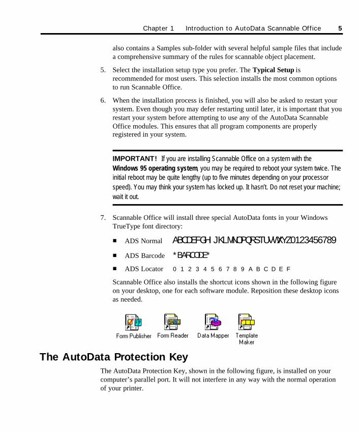
7. Scannable Office will install three special AutoData fonts in your WindowsTrueType font directory:
n ADS Normal ABCDEFGHIJKLMNOPQRSTUVWXYZ0123456789n ADS Barcode *BARCODE*n ADS Locator 0123456789ABCDEF
Scannable Office also installs the shortcut icons shown in the following figureon your desktop, one for each software module. Reposition these desktop iconsas needed.
The AutoData Protection KeyThe AutoData Protection Key, shown in the following figure, is installed on yourcomputer’s parallel port. It will not interfere in any way with the normal operationof your printer.
Chapter 1 Introduction to AutoData Scannable Office 5
SO Chapter 1 final.qxd 3/21/00 6:15 PM Page 5
AutoData Protection Key
While not absolutely necessary, it is advisable to turn off your computer systemwhile installing this device. Be careful to avoid static discharge while handling thisor any other computer hardware component.
Remove your printer cable from the parallel port. If your system has more than oneprinter port, be sure to mount the device to the LPT1 port. After installing theAutoData Protection Key, attach the printer cable to the device.
The AutoData Protection Key must be in place when using AutoData Data Mapperand Form Reader. In network installations, each station running these modules musthave a separate key installed for proper operation.
The Sample FormsThe three sample forms provided with AutoData Scannable Office are accessiblefrom the AutoData program group.
n Demo 1 (demo1.DOC) is a simple one-sheet form that demonstrates the basicuse of most of the field types available in AutoData Scannable Office. Print acopy using a laser printer. Hone your skills by trying to recreate this form usingthe scannable object features included in the Form Publisher module. If youprefer to create forms using a desktop publishing program other than MicrosoftWord, scan a clean laser-printed copy of the Demo1.DOC form on an imagingscanner. Then, practice creating each field type after reading the chapter UsingAutoData Form Publisher, later in this manual.
n Form Rules (FormRules.DOC) is a single-page summary of the positioningand spacing rules required for any form processed by Form Reader. Print a copyand keep it nearby as a reference tool. While the spacing information will provehelpful when using Form Publisher, many of the other details are alreadyautomated within the AutoData Document Template macros. The rule sheet willprove most valuable in the preparation of forms with a desktop publishingprogram such as QuarkXPress, PageMaker or Adobe InDesign. Forms created
6 Chapter 1 Introduction to AutoData Scannable Office
SO Chapter 1 final.qxd 3/21/00 6:15 PM Page 6

with these or similar programs must be scanned by an imaging scanner and thendefined using Template Maker.
n MediMed (demo.DOC) is a good example of a one-page, two-color surveyform created with Form Publisher. The respondent must enter personalinformation and rate the fictional MediMed medical group on a five-step scaleusing check marks. The form has a bar code as well as an OCR Field. Theheader demonstrates the use of a corporate logo and form title.
The MediMed form has an accompanying Access database (Demo.MDB) withsample data, which can be loaded in both Data Mapper and Form Reader. Itshows you a typical Access database.
The Demo.RST file included in the MediMed folder keeps track of scannableobject property information, so the Form Reader module will know how toprocess each scannable object field on the form.
Chapter 1 Introduction to AutoData Scannable Office 7
SO Chapter 1 final.qxd 3/21/00 6:15 PM Page 7

8 Chapter 1 Introduction to AutoData Scannable Office
SO Chapter 1 final.qxd 3/21/00 6:15 PM Page 8
9
Chapter 2Using AutoData Scannable Office
This chapter provides a brief overview of AutoData Scannable Office, including abrief description of each Scannable Office module. Several possible scenarios areexplored to help you understand the relationship between the different softwaremodules and the sequence in which you should use them. The scenarios progressfrom the simplest and most common to the more advanced. This chapter alsodescribes the different file types created by the Scannable Office software modules.
The Scannable Office ModulesScannable Office was designed to bring automated data collection to the desktop byleveraging the power of the most widely used software suite, Microsoft Office.
The Scannable Office software consists of four modules that may be launched eitherfrom the AutoData Scannable Office group in the Programs menu, or from desktopicons:
n AutoData Form Publisher
n AutoData Form Reader
n AutoData Data Mapper
n AutoData Template Maker
SO Chapter 2 final.qxd 3/21/00 6:16 PM Page 9
AutoData Form PublisherCreating a scannable form is simple when you use the powerful features ofAutoData Form Publisher. If you are already familiar with Microsoft Word, yourlearning curve may be dramatically shortened as you learn how to use the AutoDataDocument Template macros within Word to create customized, professional-lookingforms. With Form Publisher, you can transform paper-based forms into efficient datacollection tools.
Form Publisher provides several tools to make scannable form creation simple. Forexample, a customized AutoData Toolbar enables you to create scannable objects—such as check marks, hand print boxes, bar codes, OCR fields—with the click of abutton. Many of these choices are pre-defined and formatted, which eliminatesmuch of the guesswork and uncertainties that can cause delay. Simply select theappropriate properties, point your cursor at the approximate final location, and thesystem automatically creates the scannable object to your exact specifications.
Locator marks automatically appear in correct position on each page of your form.These marks contain special information that identifies the Form ID and pagenumber, and also allows the scanner to detect upside-down pages. They also helpthe scanner de-skew images. Locator marks effortlessly transform a traditional forminto a scannable form.
Form Publisher includes tools to quickly and easily group, layer, align, and spacetext boxes and scannable objects on your page. Following some simple designrules—like not overlapping any scannable objects or text fields—makes scannableforms creation efficient. Best of all, organizations can begin to collect timelyinformation in a fraction of the time previously required, and at a fraction of thecost.
Helpful message prompts open when you need guidance or perform an incorrectaction. Feel free to move, change, or delete any element on your form during thedesign phase. Once you’re confident the design job is complete, click on a specialPublish icon. The Publish routine runs a final check on your form to ensure itcomplies with some basic scannable form requirements, then automatically createsthe form template. You now have a scannable form! Going forward, AutoData FormReader will recognize your form and extract the critical information provided by therespondents.
10 Chapter 2 Using AutoData Scannable Office
SO Chapter 2 final.qxd 3/21/00 6:16 PM Page 10
AutoData Form ReaderAutoData Form Reader performs many powerful steps in the data collection process.This Scannable Office software module scans, processes, and verifies the scannabledata on your form that was created earlier in Form Publisher (via Microsoft Word),in other AutoData software applications, or in popular third-party page layoutprograms. This module recognizes existing scannable forms, processes the criticalinformation, and sends it automatically into an Access database, Excel spreadsheetor ODBC data source. If a database does not yet exist—which is usually the casefor new forms—Form Reader guides you through the creation of one. It takes onlyseconds to complete this step with the help of easy-to-use Wizards. Users appreciatethe power of Form Reader since it eliminates cumbersome data export steps, thussaving time and increasing productivity.
Form Reader is flexible in its ability to accept scanned input from various inputsources, including ISIS- or TWAIN-compliant image scanners, forms received byWinFax PRO, as well as previously scanned forms saved as Image files.
Forms may be processed either interactively—each individual form is scanned andthen “read” (interpreted) sequentially in a single pass—or in batch mode. Batchmode form processing is performed in two separate steps. First, all forms arescanned or read as a group. Then the forms are processed and verified at a differenttime, either on a standalone computer or on different networked computer stations.If an entry (such as a check mark response or a hand print entry) is mismarked orillegible, it is presented on-screen for operator verification or correction.
AutoData’s new SmartMemory™ technology means the software has the uniqueability to “learn” different hand print styles through advanced intelligent characterrecognition (ICR). The more Form Reader is used, the “smarter” the systembecomes. Over time, users perform fewer manual verification and key entry editsbecause Form Reader grows more accurate in interpreting hand print responses.
AutoData Data MapperThe Data Mapper module allows users to automatically map the scannable objectson any new or existing form to an Excel spreadsheet, Access database or ODBCdata source. Once it’s determined how the fields on a form correspond to the fieldsin the Access or Excel database, Data Mapper displays the appropriate form, table,and/or field elements in an easy-to-view grid. If you prefer, Data Mapper can takeover this task by finding matching names and mapping the fields automatically viaan Automap feature.
Chapter 2 Using AutoData Scannable Office 11
SO Chapter 2 final.qxd 3/21/00 6:16 PM Page 11
New forms can be registered in a database, and new databases can also be createdwith the help of step-by-step Wizards. In addition, edit changes can be madedirectly in any database at any time. A handy drag-and-drop interface speeds theprocess.
Advanced users will value the optional Data Mapper module included withScannable Office. Since it is optional, users do not have to learn Data Mapper inorder to take full advantage of the other Scannable Office modules. As anorganization develops more sophisticated needs, it can grow into the advancedcapabilities offered by Data Mapper.
AutoData Template MakerThe Template Maker module is provided as part of the Scannable Office softwarefor use in these situations:
n When you prefer to create forms using popular third-party page layout anddrawing programs like PageMaker, QuarkXPress and CorelDraw, rather thanusing the Form Publisher module and Microsoft Word.
n When you wish to maintain backward compatibility with forms already definedwith AutoData FORM 4.0 and higher.
Template Maker is the bridge software that enables traditional forms created outsideof Scannable Office to be both scannable and compatible with Scannable Officesoftware. Here’s an overview of how it works. First, capture a full-page image ofyour form with a scanner. Then with the aid of Template Maker, identify and defineall the scannable fields on your form. Once your form is defined in Template Maker,you can take full advantage of all of Form Reader’s powerful scanning, processingand verification capabilities, as well as its ability to map data directly to yourdatabase of choice.
In essence, you use Template Maker to manually accomplish what Form Publisherachieves automatically with its special AutoData Document Template macros andPublish feature in Microsoft Word.
Template Maker functions are covered in detail in the AutoData Template Makermanual. Please refer to that separate manual, along with the Designing Formsmanual, for further instruction.
12 Chapter 2 Using AutoData Scannable Office
SO Chapter 2 final.qxd 3/21/00 6:16 PM Page 12
Using Scannable Office: Four ScenariosDeciding which Scannable Office module to use depends on your current situation.Since many Scannable Office users will be brand new to AutoData, some will useForm Publisher to create their forms. Others will prefer to use various third-partysoftware packages. Still others will have existing databases and Form files createdin AutoData PRO software that are backward compatible with Scannable Office.
To simplify the discussion, we outline below four user scenarios which illustratewhen you would make use of each software module. Here is a brief overview ofeach scenario:
n Scenario 1 discusses the situation in which most brand new users will findthemselves—needing to create a brand new form in Form Publisher to use witha brand new database created with Form Reader.
n Scenario 2 discusses the situation in which a user creates a brand new form touse in a brand new database, but prefers to create the form in an outsidesoftware package (such as PageMaker, QuarkXPress, etc.), rather than in FormPublisher.
n Scenario 3 discusses the situation in which a user creates a brand new form inForm Publisher. However, in this scenario, they want their new form to capturedata in an existing database.
n Scenario 4 discusses the situation in which a user creates a new form in anoutside software package, rather than in Form Publisher, and then captures theform’s data in an existing database.
Chapter 2 Using AutoData Scannable Office 13
SO Chapter 2 final.qxd 3/21/00 6:16 PM Page 13
Scenario 1This scenario is based on two assumptions:
n Your form does not yet exist, and you want to create it in Form Publisher.
n There is no existing database for the data your form will capture, and you wantto create a new one.
As illustrated in the flowchart on the next page, you will use the Scannable Officesoftware as follows:
n Use Form Publisher within Microsoft Word to create your form. Chapter 4,Using AutoData Form Publisher describes how to do this in detail.
n Use Form Reader to process the completed (or filled-in) forms. Duringprocessing, Form Reader activates special Wizards to create an Access databaseor an Excel spreadsheet to hold your captured data. Chapter 5, Using AutoDataForm Reader provides detailed information on doing this.
14 Chapter 2 Using AutoData Scannable Office
SO Chapter 2 final.qxd 3/21/00 6:16 PM Page 14
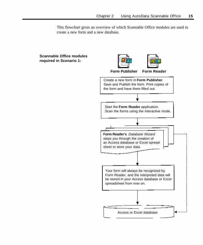
This flowchart gives an overview of which Scannable Office modules are used tocreate a new form and a new database.
Chapter 2 Using AutoData Scannable Office 15
Create a new form in Form Publisher.Save and Publish the form. Print copies ofthe form and have them filled out.
Start the Form Reader application.Scan the forms using the interactive mode.
Form Reader’s Database Wizardsteps you through the creation of an Access database or Excel spread-sheet to store your data.
Your form will always be recognized byForm Reader, and the interpreted data willbe stored in your Access database or Excelspreadsheet from now on.
Access or Excel database
Scannable Office modulesrequired in Scenario 1:
Form Publisher Form Reader
SO Chapter 2 final.qxd 3/21/00 6:16 PM Page 15
16 Chapter 2 Using AutoData Scannable Office
Scenario 2This scenario makes these assumptions:
n You have already created a form in an outside software package such asPageMaker or QuarkXPress, following the specifications of the AutoDataDesigning Forms manual.
n You want the Scannable Office software to process the form and capture its datain a brand new database.
As illustrated by the flowchart on the next page, you will use the Scannable Officesoftware as follows:
n Use Template Maker to define and locate the fields on your existing form. Referto the AutoData Template Maker manual for instructions on how to do this.
n Use Form Reader to process completed forms. During processing, Form Readeractivates special Wizards to create an Access database or an Excel spreadsheetto hold your captured data. Chapter 5, Using AutoData Form Reader providesdetailed information on doing this.
SO Chapter 2 final.qxd 3/21/00 6:16 PM Page 16
Chapter 2 Using AutoData Scannable Office 17
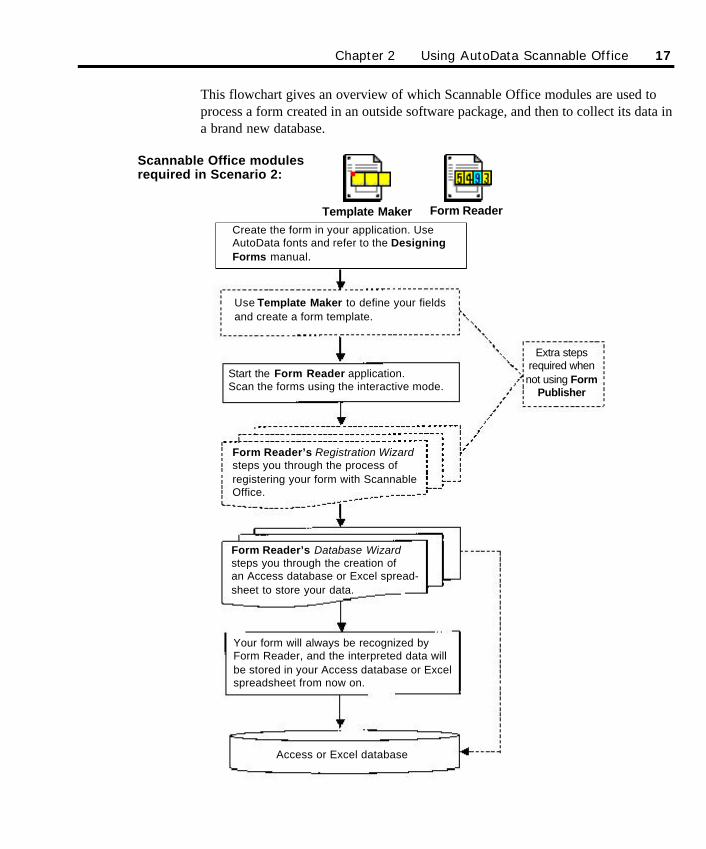
This flowchart gives an overview of which Scannable Office modules are used toprocess a form created in an outside software package, and then to collect its data ina brand new database.
Use Template Maker to define your fieldsand create a form template.
Extra stepsrequired whennot using Form
Publisher
Access or Excel database
Your form will always be recognized byForm Reader, and the interpreted data willbe stored in your Access database or Excelspreadsheet from now on.
Form Reader’s Database Wizardsteps you through the creation of an Access database or Excel spread-sheet to store your data.
Form Reader’s Registration Wizardsteps you through the process of registering your form with ScannableOffice.
Start the Form Reader application. Scan the forms using the interactive mode.
Template Maker Form Reader
Scannable Office modulesrequired in Scenario 2:
Create the form in your application. UseAutoData fonts and refer to the DesigningForms manual.
SO Chapter 2 final.qxd 3/21/00 6:16 PM Page 17
18 Chapter 2 Using AutoData Scannable Office
Scenario 3This scenario makes these assumptions:
n Your form does not yet exist, and you want to create it in Form Publisher.
n You want to use an existing database to capture your new form’s data.
As illustrated in the flowchart on the next page, you will use the Scannable Officesoftware as follows:
n Use Form Publisher to create your form. Chapter 4, Using AutoData FormPublisher describes how to do this in detail.
n Use Data Mapper to map your data output to match the structure of an existingdatabase (an Access .MDB file, an Excel .XLS spreadsheet, or an ODBC datasource). Chapter 6, Using AutoData Data Mapper gives detailed informationon how to do this.
n Use Form Reader to process completed forms and store the data in yourdatabase. Chapter 5, Using AutoData Form Reader provides detailedinformation on doing this.
SO Chapter 2 final.qxd 3/21/00 6:16 PM Page 18
Chapter 2 Using AutoData Scannable Office 19
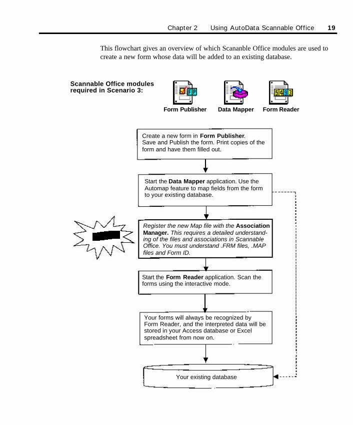
This flowchart gives an overview of which Scananble Office modules are used tocreate a new form whose data will be added to an existing database.
Your existing database
Your forms will always be recognized byForm Reader, and the interpreted data will bestored in your Access database or Excelspreadsheet from now on.
Start the Form Reader application. Scan theforms using the interactive mode.
Register the new Map file with the AssociationManager. This requires a detailed understand-ing of the files and associations in ScannableOffice. You must understand .FRM files, .MAPfiles and Form ID.
Start the Data Mapper application. Use theAutomap feature to map fields from the formto your existing database.
Create a new form in Form Publisher.Save and Publish the form. Print copies of theform and have them filled out.
Scannable Office modulesrequired in Scenario 3:
Form Publisher Data Mapper Form Reader
SO Chapter 2 final.qxd 3/21/00 6:16 PM Page 19
Scenario 4This scenario makes the following assumptions:
n You have already created a form in an outside software package such asPageMaker or QuarkXPress, following the specifications of the DesigningForms manual.
n You want Scannable Office software to process the form and add its data to anexisting database.
As illustrated by the flowchart on the next page, you will use the Scannable Officesoftware as follows:
n Use Template Maker to define and locate the fields on your existing form. Referto the AutoData Template Maker manual for more instructions on how to dothis.
n Use Data Mapper to map your data output to match the structure of an existingdatabase (an Access .MDB file, an Excel .XLS spreadsheet, or an ODBC datasource). Chapter 6, Using AutoData Data Mapper gives detailed information onhow to do this.
n Use Form Reader to process completed forms and store the data in yourdatabase. Chapter 5, Using AutoData Form Reader provides detailedinformation on doing this.
20 Chapter 2 Using AutoData Scannable Office
SO Chapter 2 final.qxd 3/21/00 6:16 PM Page 20
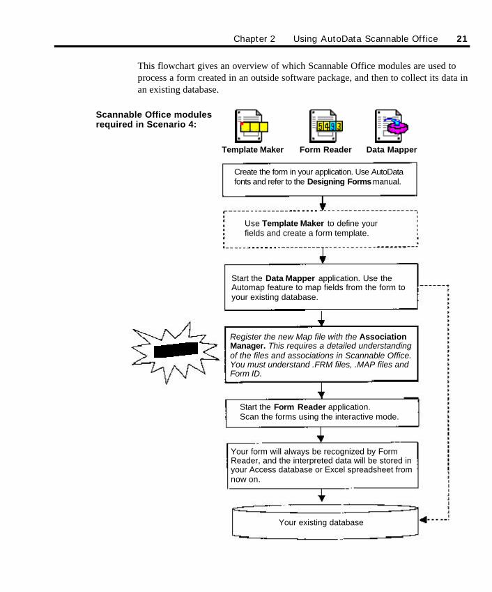
This flowchart gives an overview of which Scannable Office modules are used toprocess a form created in an outside software package, and then to collect its data inan existing database.
Chapter 2 Using AutoData Scannable Office 21
Your existing database
Your form will always be recognized by FormReader, and the interpreted data will be stored inyour Access database or Excel spreadsheet fromnow on.
Start the Form Reader application. Scan the forms using the interactive mode.
Register the new Map file with the AssociationManager. This requires a detailed understandingof the files and associations in Scannable Office.You must understand .FRM files, .MAP files andForm ID.
Create the form in your application. Use AutoDatafonts and refer to the Designing Formsmanual.
Use Template Maker to define yourfields and create a form template.
Start the Data Mapper application. Use theAutomap feature to map fields from the form toyour existing database.
Template Maker Form Reader
Scannable Office modulesrequired in Scenario 4:
Data Mapper
SO Chapter 2 final.qxd 3/21/00 6:16 PM Page 21
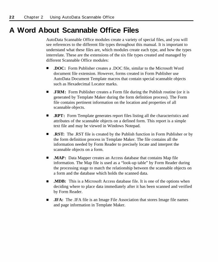
A Word About Scannable Office FilesAutoData Scannable Office modules create a variety of special files, and you willsee references to the different file types throughout this manual. It is important tounderstand what these files are, which modules create each type, and how the typesinterrelate. These are the extensions of the six file types created and managed bydifferent Scannable Office modules:
n .DOC: Form Publisher creates a .DOC file, similar to the Microsoft Worddocument file extension. However, forms created in Form Publisher useAutoData Document Template macros that contain special scannable objectssuch as Hexadecimal Locator marks.
n .FRM: Form Publisher creates a Form file during the Publish routine (or it isgenerated by Template Maker during the form definition process). The Formfile contains pertinent information on the location and properties of allscannable objects.
n .RPT: Form Template generates report files listing all the characteristics andattributes of the scannable objects on a defined form. This report is a simpletext file and may be viewed in Windows Notepad.
n .RST: The .RST file is created by the Publish function in Form Publisher or bythe form definition process in Template Maker. The file contains all theinformation needed by Form Reader to precisely locate and interpret thescannable objects on a form.
n .MAP: Data Mapper creates an Access database that contains Map fileinformation. The Map file is used as a “look-up table” by Form Reader duringthe processing stage to match the relationship between the scannable objects ona form and the database which holds the scanned data.
n .MDB: This is a Microsoft Access database file. It is one of the options whendeciding where to place data immediately after it has been scanned and verifiedby Form Reader.
n .IFA: The .IFA file is an Image File Association that stores Image file namesand page information in Template Maker.
22 Chapter 2 Using AutoData Scannable Office
SO Chapter 2 final.qxd 3/21/00 6:16 PM Page 22
23
Chapter 3Designing Forms
AutoData Scannable Office provides a quick and efficient way to create scannableforms for collecting data. To gain maximum benefit from the program so that thenecessary data is collected, it is important to consider the form’s final format.
Before the process of form design begins, consider the project scope from start tofinish or, better yet, from finish to start. What should the data look like in itscompleted format? What is the best way to capture specific data? Will data be addedto an existing database or spreadsheet? Giving serious thought to these issues upfront will be apparent at project completion when the scannable form looksprofessional, is simple to administer, easy for respondents to understand, and thedata collected at the back end is accurate and complete.
Only the imagination and the creativity of the end user limit the possibleapplications for AutoData Scannable Office forms. Ideal applications include:
n Membership applications
n Satisfaction surveys
n Course evaluations
n Product or event registration
n Customer profiles
n New patient health history and insurance information
n Chart audits
n Personality and psychological testing
n Inventory tracking
n Membership enrollment
SO Chapter 3 final.qxd 3/21/00 6:21 PM Page 23
Form Fields: Asking the Right QuestionTo gather the feedback or data required, most forms ask for information to becompleted. Each entry, regardless of type, is called a field or scannable objectScannable Office uses six basic field types:
n Hand Print Fields
n Check Mark Fields
n Bar Code Fields
n OCR Fields
n Image Capture Fields
n Key Entry Fields
Each field type will be explained briefly below and in much greater detail in theAutoData Form Publisher chapter. In planning the design of a form, determinewhich type of field best captures the information required, and makes completingthe form as easy as possible.
For example, if you want to know what computer platform your respondents use,providing a fill-in-the-blank Hand Print Field to answer the question may elicit awide range of answers—from IBM compatible, to Pentium III or MicronMillennium. In this example, all three answers could easily refer to the samecomputer, rendering your data virtually useless. However, if you choose instead toask your question in the form of a multiple-choice Check Mark Field, the range ofchoices are narrowed significantly. This format makes it much easier to capture andprocess the data. Including “Other” as a check mark option and adding a Key EntryField to catch the few odd responses is another way of providing a complete rangeof answer options.
Asking the right question—and asking it in the right way—is critical to creating awell designed form.
Form Layout: Inviting Accurate AnswersThe appearance of your form is an important element in good form design. Acluttered, crowded page can intimidate some, confuse others, and make it very easyfor questions to be missed. Keep in mind that Scannable Office can process formsup to 25 pages long.
24 Chapter 3 Designing Forms
SO Chapter 3 final.qxd 3/21/00 6:21 PM Page 24
A well designed form leads the respondent easily from question to question, fromfield to field. The individual should never have to ask, “Where do I go next?”Designing a form that is clean and easy to use is a good investment of your time andeffort.
Most forms are fairly self-explanatory, but it’s good policy to clearly label yourforms so respondents can tell at a glance exactly what they are filling out. Askingwell constructed questions and including instructions for filling out the form canmean the difference between blank response fields and completed ones.
Six Basic Field Types
1. Hand Print FieldsAutoData Form Reader can recognize hand printed characters with great accuracy. AHand Print Field is a series of connected boxes that will contain hand printed lettersand numbers. In order to maintain accuracy, certain rules govern how an individualcompletes the field:
n Letters must be all uppercase (capital letters).
n Only one character may be printed in each box.
n Letters and numbers should be contained entirely within the boxes of the field.None of the letters or numbers should touch any lines of the boxes.
Characters printed in Hand Print Fields must be printed neatly. The accuracy withwhich the field is processed directly depends on the quality of the handwriting.Straight lines must be clearly distinguishable from curved ones.
Hand Print Fields are most appropriate for use in situations where the user isentering a name, telephone number, social security number, etc. The Hand PrintField is limited to a maximum of 28 characters. When a longer, free-form responseis desired, an Image Capture Field or a Key Entry Field is clearly more appropriate.These field types are described below.
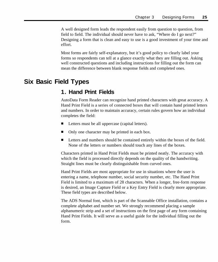
The ADS Normal font, which is part of the Scannable Office installation, contains acomplete alphabet and number set. We strongly recommend placing a samplealphanumeric strip and a set of instructions on the first page of any form containingHand Print Fields. It will serve as a useful guide for the individual filling out theform.
Chapter 3 Designing Forms 25
SO Chapter 3 final.qxd 3/21/00 6:21 PM Page 25
Please print as neatly as possible. Use ALL CAPS. Do not touch the box sides.
ABCDEFGHIJKLMNOPQRSTUVWXYZ0123456789Sample instructions and alphanumeric hand print characters using ADS Normal font
The Hand Print Field option in Form Publisher offers a comprehensive list of pre-defined Hand Print Fields including Personal Name, Address, Company and PhoneNumber to name a few. If the pre-defined listing does not offer what you want, feelfree to create a User Defined Hand Print Field.
A User Defined Hand Print Field can contain any combination of up to 28 numbers,letters or special characters. The contents and format of this field are entirely up toyou. Examples of uses for this type of field include passwords, inventory productnumbers, and so on.
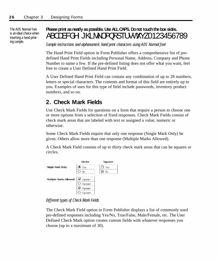
2. Check Mark FieldsUse Check Mark Fields for questions on a form that require a person to choose oneor more options from a selection of fixed responses. Check Mark Fields consist ofcheck mark areas that are labeled with text or assigned a value, numeric orotherwise.
Some Check Mark Fields require that only one response (Single Mark Only) begiven. Others allow more than one response (Multiple Marks Allowed).
A Check Mark Field consists of up to thirty check mark areas that can be squares orcircles.
Different types of Check Mark Fields
The Check Mark Field option in Form Publisher displays a list of commonly usedpre-defined responses including Yes/No, True/False, Male/Female, etc. The UserDefined Check Mark option creates custom fields with whatever responses youchoose (up to a maximum of 30).
The ADS Normal fontis an ideal choice wheninserting a hand print-ing sample.
26 Chapter 3 Designing Forms
SO Chapter 3 final.qxd 3/21/00 6:21 PM Page 26
3. Bar Code FieldsIn older AutoData FORM programs, Bar Code Fields were generally used to createa unique “Form ID.” The new Hexadecimal Locators created by Form Publishermake this unnecessary, since the Form ID is now embedded in the Locators.
Bar codes may be useful in placing product serial numbers on forms. FormPublisher is fully capable of creating merged data bar codes, or a “frame” in whicha bar code label may be affixed. The Advanced Topics chapter contains detailedinformation on using Microsoft Word’s mail merge capability to create Bar CodeFields.
Scannable Office installs an ADS Barcode font which is equivalent to a Barcode 3 of 9.
*BARCODE*Sample bar code using ADS Barcode font
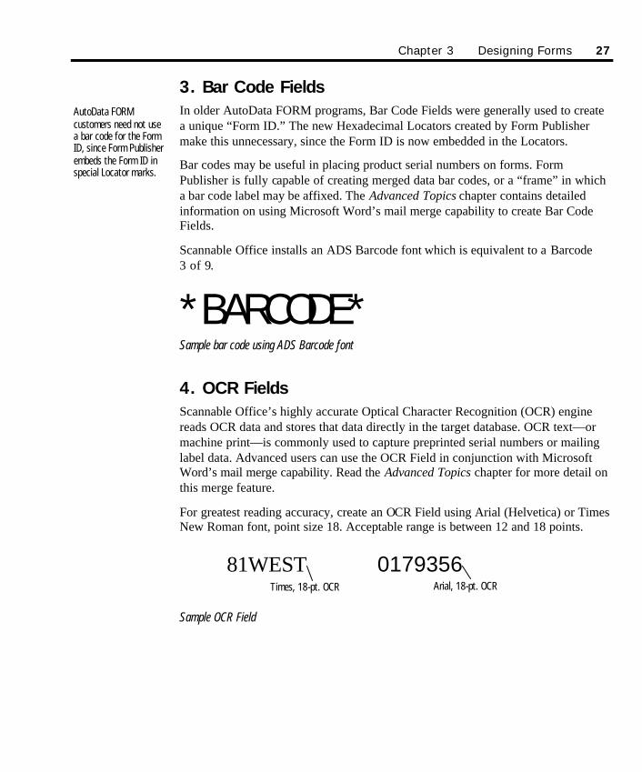
4. OCR FieldsScannable Office’s highly accurate Optical Character Recognition (OCR) enginereads OCR data and stores that data directly in the target database. OCR text—ormachine print—is commonly used to capture preprinted serial numbers or mailinglabel data. Advanced users can use the OCR Field in conjunction with MicrosoftWord’s mail merge capability. Read the Advanced Topics chapter for more detail onthis merge feature.
For greatest reading accuracy, create an OCR Field using Arial (Helvetica) or TimesNew Roman font, point size 18. Acceptable range is between 12 and 18 points.
81WEST 0179356
Sample OCR Field
AutoData FORM customers need not usea bar code for the FormID, since Form Publisherembeds the Form ID inspecial Locator marks.
Chapter 3 Designing Forms 27
Times, 18-pt. OCR Arial, 18-pt. OCR
SO Chapter 3 final.qxd 3/21/00 6:21 PM Page 27
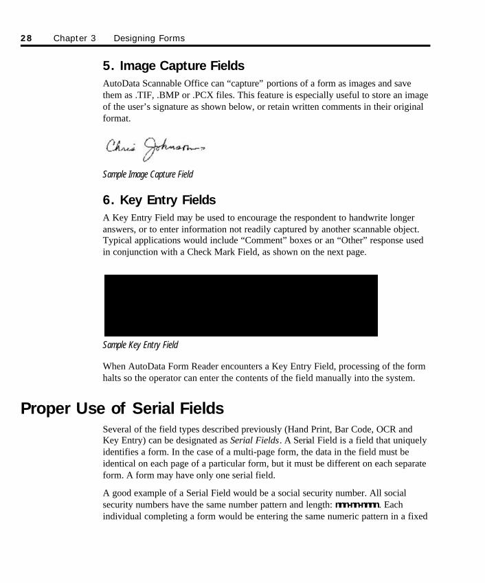
5. Image Capture FieldsAutoData Scannable Office can “capture” portions of a form as images and savethem as .TIF, .BMP or .PCX files. This feature is especially useful to store an imageof the user’s signature as shown below, or retain written comments in their originalformat.
Sample Image Capture Field
6. Key Entry FieldsA Key Entry Field may be used to encourage the respondent to handwrite longeranswers, or to enter information not readily captured by another scannable object.Typical applications would include “Comment” boxes or an “Other” response usedin conjunction with a Check Mark Field, as shown on the next page.
Sample Key Entry Field
When AutoData Form Reader encounters a Key Entry Field, processing of the formhalts so the operator can enter the contents of the field manually into the system.
Proper Use of Serial FieldsSeveral of the field types described previously (Hand Print, Bar Code, OCR andKey Entry) can be designated as Serial Fields. A Serial Field is a field that uniquelyidentifies a form. In the case of a multi-page form, the data in the field must beidentical on each page of a particular form, but it must be different on each separateform. A form may have only one serial field.
A good example of a Serial Field would be a social security number. All socialsecurity numbers have the same number pattern and length: nnn-nn-nnnn. Eachindividual completing a form would be entering the same numeric pattern in a fixed
28 Chapter 3 Designing Forms
SO Chapter 3 final.qxd 3/21/00 6:21 PM Page 28
format field, and yet each form’s data would be unique and would uniquely identifythat form.
Serial numbers used as Serial Fields are best entered using merge capability oradhesive labels. You might consider asking the respondent to print the number in aHand Print Field, but be wary of this approach if the serial numbers are long. Thelonger the number, the higher the error potential, and the more difficult the errorcorrection task.
Page Length and Page Order RestrictionsScannable Office can create, map and read forms up to 25 pages long. Pagenumbering is automatic. If you use a Serial Field, pages do not have to be scannedin page sequence. Multi-page forms without Serial Fields must be processed in pageorder. Scannable Office will automatically identify each page and correctlysequence the output data.
Page Size RequirementsScannable Office can handle any size form your scanner is capable of scanning, upto a maximum of 11"×17", portrait or landscape. When you first install the AutoDataDocument Template in Microsoft Word, a blank letter size page (8½"×11") opens. Ifyou prefer a different size, immediately change the page size (choose Page Setupfrom the File menu, then click on the Paper Size tab).
Don’t select an odd-sized page simply because you can. Think twice beforechanging from the default size. Consider how the form will be reproduced, how itwill be handled and distributed, how it will be returned, processed and filed. Odd-sized forms can pose processing and handling challenges.
Test how a scanner’s automatic document feeder (ADF) handles an odd-sized form.Most ADFs are designed to handle standard business size sheets (letter, legal, A4).A half-sheet (8½"×5½") or quarter-sheet (4¼"×5½") form may jam or skew badly.This does not mean small forms can’t be created, but it does mean that non-standardform sizes may need to be hand fed as they are scanned. If a large number of formsmust be processed, give serious thought to the cost of processing time associatedwith hand feeding single sheets. It may be worthwhile to redesign the form.
If you are planning to offer individuals the capability of returning forms by fax,remember that the default sheet size for most fax machines is letter size. WinFaxPRO, the AutoData supported software for incoming faxed forms, automaticallyreduces a large sheet to letter size format for printing or on-screen reading. A
Chapter 3 Designing Forms 29
SO Chapter 3 final.qxd 3/21/00 6:21 PM Page 29
reduced form will no longer correspond to the form originally created in FormPublisher, and it will be unreadable by AutoData Form Reader.
Page OrientationA form’s pages are formatted in a vertical (portrait) or horizontal (landscape)orientation. Choose the shape that best accommodates your needs as well as therespondent’s. Even if a scanner cannot handle an 11" wide form, Scannable Officepermits the use of this format. First, change the page orientation to landscape as it isbeing designed in Form Publisher. Then, prior to scanning the forms, instruct FormReader to rotate the form 90 degrees. Place your forms in the scanner’s automaticdocument feeder in a portrait stack. Form Reader automatically rotates each form’simage 90 degrees during the scan process, so all the scannable objects arerecognized in their original landscape position. During processing, horizontal andvertical forms must be handled in separate batches and cannot be mixed together.
Locator MarksWhen AutoData Form Publisher initially powers up, a blank form page appears onscreen with five black squares in the corners. These are called Locator marks, whichcontain hexadecimal characters. Scannable Office uses these marks to identify aform, number its pages, and detect if the form is being scanned upside down. Theyare also used to correct minor skewing of the form’s scanned image.
Form Publisher automatically places Locator marks in their correct position. Thesemarks should never be moved or altered. As new pages are added to a multi-pageform, the bottom right Locator marks will differ on each page. Scannable Officeuses these marks to keep track of which page of a multi-page form it is processing.
IMPORTANT! All forms created by Form Publisher or defined with Template Maker MUSTinclude Locator marks in all four corners of the form. These marks are an essential part ofan AutoData scannable form; a form cannot be printed or processed correctly without them.
If you are duplicating forms on a copier or printing them on a laser printer, do notremove the Locator marks from the master copy with correction fluid or correctiontape. This action renders the printed forms unscannable by AutoData Form Reader.If forms are commercially printed, be sure to explain what the marks are, so a well-meaning plate maker will not mask them out.
30 Chapter 3 Designing Forms
SO Chapter 3 final.qxd 3/21/00 6:21 PM Page 30
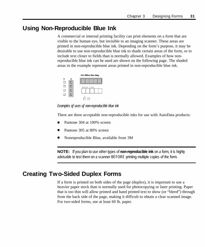
Using Non-Reproducible Blue Ink A commercial or internal printing facility can print elements on a form that arevisible to the human eye, but invisible to an imaging scanner. These areas areprinted in non-reproducible blue ink. Depending on the form’s purpose, it may bedesirable to use non-reproducible blue ink to shade certain areas of the form, or toinclude text closer to fields than is normally allowed. Examples of how non-reproducible blue ink can be used are shown on the following page. The shadedareas in the example represent areas printed in non-reproducible blue ink.
Examples of uses of non-reproducible blue ink
There are three acceptable non-reproducible inks for use with AutoData products:
n Pantone 304 at 100% screen
n Pantone 305 at 80% screen
n Nonreproducible Blue, available from 3M
NOTE: If you plan to use other types of non-reproducible ink on a form, it is highlyadvisable to test them on a scanner BEFORE printing multiple copies of the form.
Creating Two-Sided Duplex FormsIf a form is printed on both sides of the page (duplex), it is important to use aheavier paper stock than is normally used for photocopying or laser printing. Paperthat is too thin will allow printed and hand printed text to show (or “bleed”) throughfrom the back side of the page, making it difficult to obtain a clear scanned image.For two-sided forms, use at least 60 lb. paper.
Chapter 3 Designing Forms 31
SO Chapter 3 final.qxd 3/21/00 6:21 PM Page 31
In addition, duplex forms must be designed in even-numbered sets for properscanning. At a minimum, each page must have the proper Locator marks on thefront and back side, as well as the proper bar codes or Serial Fields that may appearon earlier pages. Even if there are no questions or text appearing on the back side ofthe form—and the page is otherwise blank—the even-numbered page must beincluded to ensure proper scanning.
Printing Your FormFor short form runs, especially those using print-merge capabilities for an OCRserial field, a laser printer will yield good results. High-end laser printers are alsocapable of producing large numbers of copies economically, and some models canefficiently produce, collate and even staple multi-page forms. Keep in mind,however, that laser-printed forms will vary from page to page. Often there can besignificant variations between the first and last page of a large laser-printed runbecause of the electrostatic technology employed. Variable roller speed as paper ispulled through the paper path can also contribute to image distortion.
When you need to produce a large quantity of scannable forms, it is advisable to usea high quality office copier. Make sure the copier is not low on toner. In addition,the glass platform must be spotless so the copies are free of spots.
For best results, use a quality in-house or commercial print shop, and provide aclean camera-ready master created on a laser printer. If your printer prefers to workfrom digital originals, copy the Word .DOC file on a disk. The other companionfiles created during the Publish process (e.g., .FRM) are not required. However, anyAutoData fonts (ADS Normal, ADS Barcode and ADS Locator) used to create theform must be provided. If file transfer takes place using the Adobe Acrobat PortableDocument File (.PDF) format, be sure to embed all the fonts. As a precaution, alsoprovide a copy of the fonts to insure proper reproduction. Don’t forget to tell theprinter that the corner Locator marks are an essential part of a scannable form andshould be printed exactly as they appear.
Other Special Handling Tips
Folded Forms Forms that have been folded could present problems when an automatic documentfeeder is processing them. They have a tendency to skew or even jam the feedermechanism, and they may also degrade the integrity of scanned data.
Forms scanned on aduplex scanner mustinclude an even numberof pages to scan correctly.
32 Chapter 3 Designing Forms
SO Chapter 3 final.qxd 3/21/00 6:21 PM Page 32
When you receive folded forms returned inside a business size envelope, we suggestyou straighten the forms by unfolding them in the opposite direction, then layingthem out in a flat stack with a large, heavy book on top. Additionally, a commercialprinter can put “fold lines” into the form’s margins as long as the fold lines aren’ttoo close to scannable areas. It’s important to be aware of the potential problemfolding forms poses. Adjust verification levels in the processing phase as you deemappropriate.
Stapled FormsStapling forms also creates problems. The commonly used top left diagonal stapleposition corresponds to the top left Locator mark position and should NOT be used.If it is necessary to staple the pages of a form, position the staple in a horizontal orvertical position in the one-inch margin of a form. Better yet, consider a top-centerstaple position or several staples along the left side.
When stapled forms are returned, use care in removing the staples prior toprocessing. Stapled forms, even after the staples have been removed, have atendency to stick together. Straighten any folds on the form or dog ears on itscorners, and then press the staple holes tightly between thumb and forefinger for asecond or two. Fanning the sheets prior to loading them in the automatic documentfeeder will also help to eliminate this problem.
Chapter 3 Designing Forms 33
SO Chapter 3 final.qxd 3/21/00 6:21 PM Page 33

34 Chapter 3 Designing Forms
SO Chapter 3 final.qxd 3/21/00 6:21 PM Page 34
35
Chapter 4Using AutoData Form Publisher
AutoData Form Publisher uses a highly sophisticated document template that loadsseamlessly with Microsoft Word and helps automate the process of creating a form.It adds a special AutoData Toolbar and additional menus to the normal Word view,to assist you in creating and positioning scannable objects and descriptive textblocks on your form.
When you finish designing your form within Word, the “Publish” feature of FormPublisher reviews your form and makes sure it conforms to the positioning andspacing standards required for accurate scanning and processing by Form Reader.The Publish process also creates two additional files used by Form Reader forprocessing.
This chapter describes how to use the AutoData Form Publisher software module ofScannable Office to create your forms. It has three main parts.
The first part, Starting Out, describes how to launch Form Publisher and open a newdocument. It describes the AutoData Toolbar, the purpose of the Locator marks, andgives guidelines on document and page setup. It also explains how to open existingform documents.
The second part, Defining Scannable Objects, describes the different field types youcan use, and gives detailed instructions on adding these and other elements to aform.
The third part of the chapter, Publishing Your Form, describes how to Publish yourdocument for use with AutoData Form Reader.
SO Chapter 4 final.qxd 3/21/00 6:22 PM Page 35
36 Chapter 4 Using AutoData Form Publisher
Starting Out
Launching Form Publisher and Opening a New Form Document There are two methods of launching the Form Publisher software. The first methodis to launch the software from your desktop or Start menu. This method opens acopy of Word, and then overlays the program with the special AutoData DocumentTemplate. The first time you use Form Publisher, this is the method you should use.
The second method, described later in this section under Opening Existing Files,can be used when you have already created and saved files. Simply open MicrosoftWord, and then open the Form Publisher file using the menu commands or tools.Doing this also launches Form Publisher.
Ø To launch Form Publisher and open a new form from the desktop or theStart menu:
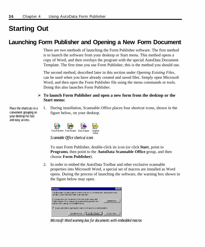
1. During installation, Scannable Office places four shortcut icons, shown in thefigure below, on your desktop.
Scannable Office shortcut icons
To start Form Publisher, double-click its icon (or click Start, point toPrograms, then point to the AutoData Scannable Office group, and thenchoose Form Publisher).
2. In order to embed the AutoData Toolbar and other exclusive scannableproperties into Microsoft Word, a special set of macros are installed as Wordopens. During the process of launching the software, the warning box shown inthe figure below may open.
Microsoft Word warning box for documents with embedded macros
Place the shortcuts in aconvenient grouping onyour desktop for fastand easy access.
SO Chapter 4 final.qxd 3/21/00 6:22 PM Page 36
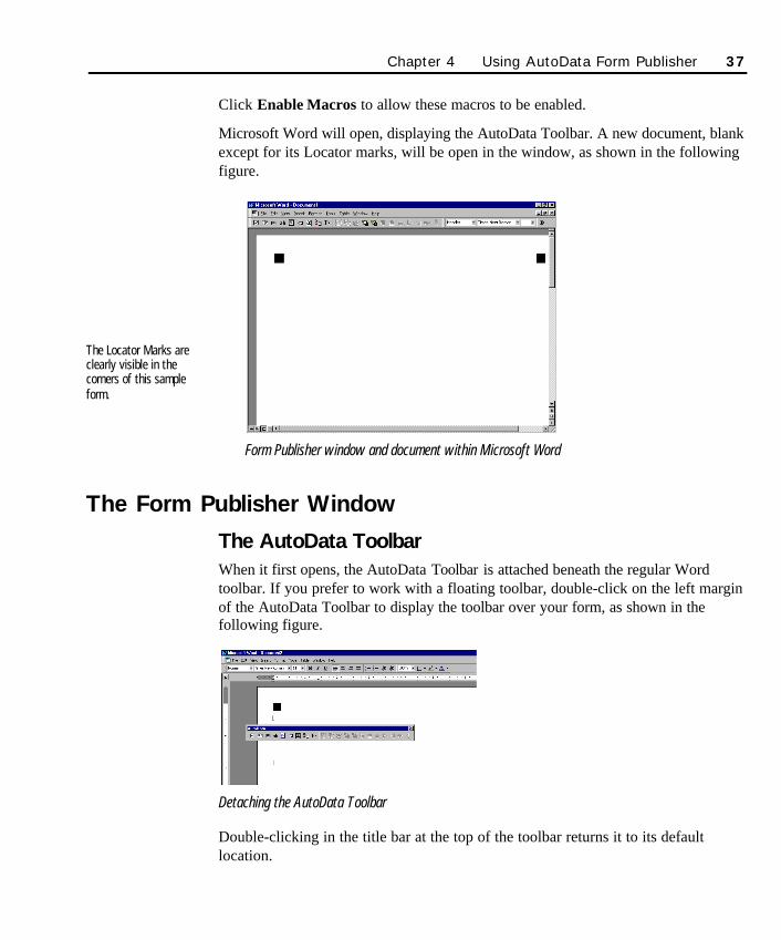
Click Enable Macros to allow these macros to be enabled.
Microsoft Word will open, displaying the AutoData Toolbar. A new document, blankexcept for its Locator marks, will be open in the window, as shown in the followingfigure.
Form Publisher window and document within Microsoft Word
The Form Publisher Window
The AutoData ToolbarWhen it first opens, the AutoData Toolbar is attached beneath the regular Wordtoolbar. If you prefer to work with a floating toolbar, double-click on the left marginof the AutoData Toolbar to display the toolbar over your form, as shown in thefollowing figure.
Detaching the AutoData Toolbar
Double-clicking in the title bar at the top of the toolbar returns it to its defaultlocation.
Chapter 4 Using AutoData Form Publisher 37
The Locator Marks areclearly visible in thecorners of this sampleform.
SO Chapter 4 final.qxd 3/21/00 6:22 PM Page 37
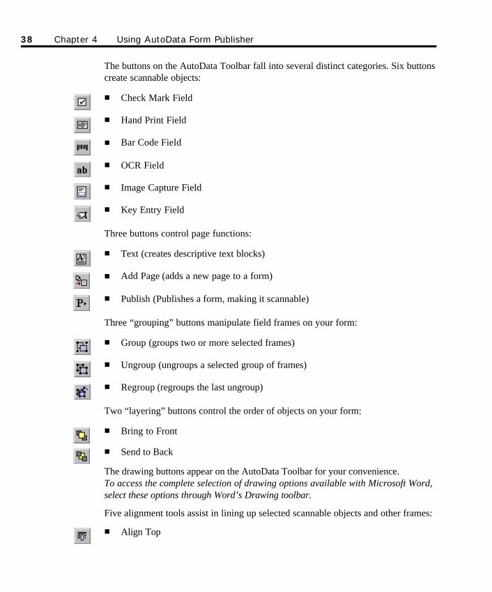
The buttons on the AutoData Toolbar fall into several distinct categories. Six buttonscreate scannable objects:
n Check Mark Field
n Hand Print Field
n Bar Code Field
n OCR Field
n Image Capture Field
n Key Entry Field
Three buttons control page functions:
n Text (creates descriptive text blocks)
n Add Page (adds a new page to a form)
n Publish (Publishes a form, making it scannable)
Three “grouping” buttons manipulate field frames on your form:
n Group (groups two or more selected frames)
n Ungroup (ungroups a selected group of frames)
n Regroup (regroups the last ungroup)
Two “layering” buttons control the order of objects on your form:
n Bring to Front
n Send to Back
The drawing buttons appear on the AutoData Toolbar for your convenience. To access the complete selection of drawing options available with Microsoft Word,select these options through Word’s Drawing toolbar.
Five alignment tools assist in lining up selected scannable objects and other frames:
n Align Top
38 Chapter 4 Using AutoData Form Publisher
SO Chapter 4 final.qxd 3/21/00 6:22 PM Page 38
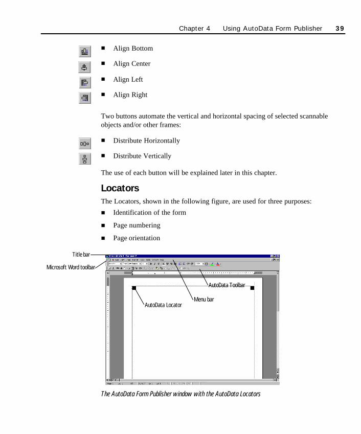
n Align Bottom
n Align Center
n Align Left
n Align Right
Two buttons automate the vertical and horizontal spacing of selected scannableobjects and/or other frames:
n Distribute Horizontally
n Distribute Vertically
The use of each button will be explained later in this chapter.
LocatorsThe Locators, shown in the following figure, are used for three purposes:
n Identification of the form
n Page numbering
n Page orientation
The AutoData Form Publisher window with the AutoData Locators
Chapter 4 Using AutoData Form Publisher 39
Title bar
Menu bar
Microsoft Word toolbar
AutoData Toolbar
AutoData Locator
SO Chapter 4 final.qxd 3/21/00 6:22 PM Page 39
Each page has five Locators. The upper left, upper right, and lower left Locatorsidentify the page as a form to AutoData Form Reader and help it de-skew the pageif the scan is not perfectly straight.
The lower right Locators uniquely identify the page number and page orientation. Ifyour form is being duplicated or printed by others, make certain that these Locatormarks are not inadvertently removed.
Page Setup for New FormsThe default page size is a standard letter size (8½"×11"), portrait orientation. If youwant your form to be a different size or orientation, change it now.
Ø To change the page size or orientation:
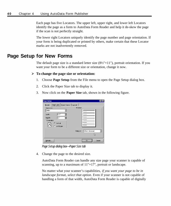
1. Choose Page Setup from the File menu to open the Page Setup dialog box.
2. Click the Paper Size tab to display it.
3. Now click on the Paper Size tab, shown in the following figure.
Page Setup dialog box—Paper Size tab
4. Change the page to the desired size.
AutoData Form Reader can handle any size page your scanner is capable ofscanning, up to a maximum of 11"×17", portrait or landscape.
No matter what your scanner’s capabilities, if you want your page to be inlandscape format, select that option. Even if your scanner is not capable ofhandling a form of that width, AutoData Form Reader is capable of digitally
40 Chapter 4 Using AutoData Form Publisher
SO Chapter 4 final.qxd 3/21/00 6:22 PM Page 40
rotating the form as it is being processed. Be sure the “Apply to” window reads“Whole document” so that any added pages will match your first page.
IMPORTANT! Do not reduce the margin settings. Form Publisher requiresmargins to be one-half inch. The primary purpose of the one-half inch limitation is toallow Form Reader to find the Locator marks on skewed forms. If the margins are toosmall, Form Reader might miss the Locator marks during the scan, rendering the pageunreadable.
Document Setup Considerations
Use of type styles in Normal Style templateMicrosoft Word’s default text style is “Normal,” which means that the default fontis Times New Roman, point size 10. While you are given some leeway in changingthe Normal Style definition, it is strongly recommended that you keep all fonts 18points or smaller. In fact, we encourage you to keep your point size between 10 and14 points. By adhering to this guideline, you can avoid unexpected form processingproblems later.
Feel free to create and define new styles for use within descriptive text boxes. Givethese styles their own unique names. A consistent use of type sizes and styles in thedescriptive text boxes throughout your form will give your finished product a moreuniform and professional appearance.
Placing objects on the form page To avoid confusing AutoData Form Reader, follow these simple rules:
n Never put any text, field, line or other object within 1/8" inch of any other field,line, check mark area, text, object, etc. This rule is applicable under allcircumstances, regardless of ink color.
n Never overlap scannable object frames and/or descriptive text boxes.
n Do not place anything outside of an imaginary rectangle encompassing theLocator marks, and never place any object near the corner Locators that is ofroughly the same size as a corner Locator mark. The corner Locator marksdefine the outside edges of your form.
Chapter 4 Using AutoData Form Publisher 41
SO Chapter 4 final.qxd 3/21/00 6:22 PM Page 41
NOTE: A Word document called FORM RULES (FormRules.DOC) is installed as part ofyour Scannable Office installation (in the AutoData Scannable Office group, in the Samplesmenu). Print a copy for reference purposes. It represents a concise summary of all thespacing considerations that affect the design and scannability of a form.
Placing scannable objects and text blocks on your form is much easier if you canactually see the margins. Use Word’s Text Boundaries option to display them.
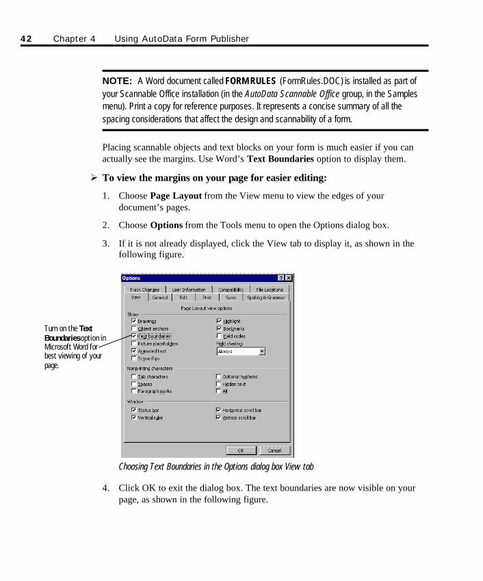
Ø To view the margins on your page for easier editing:
1. Choose Page Layout from the View menu to view the edges of yourdocument’s pages.
2. Choose Options from the Tools menu to open the Options dialog box.
3. If it is not already displayed, click the View tab to display it, as shown in thefollowing figure.
Choosing Text Boundaries in the Options dialog box View tab
4. Click OK to exit the dialog box. The text boundaries are now visible on yourpage, as shown in the following figure.
42 Chapter 4 Using AutoData Form Publisher
Turn on the TextBoundariesoption inMicrosoft Word forbest viewing of yourpage.
SO Chapter 4 final.qxd 3/21/00 6:22 PM Page 42
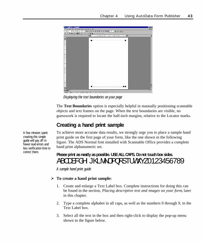
Displaying the text boundaries on your page
The Text Boundaries option is especially helpful in manually positioning scannableobjects and text frames on the page. When the text boundaries are visible, noguesswork is required to locate the half-inch margins, relative to the Locator marks.
Creating a hand print sampleTo achieve more accurate data results, we strongly urge you to place a sample handprint guide on the first page of your form, like the one shown in the followingfigure. The ADS Normal font installed with Scannable Office provides a completehand print alphanumeric set.
Please print as neatly as possible. USE ALL CAPS. Do not touch box sides.
ABCDEFGHIJKLMNOPQRSTUWXYZ0123456789A sample hand print guide
Ø To create a hand print sample:
1. Create and enlarge a Text Label box. Complete instructions for doing this canbe found in the section, Placing descriptive text and images on your form, laterin this chapter.
2. Type a complete alphabet in all caps, as well as the numbers 0 through 9, in theText Label box.
3. Select all the text in the box and then right-click to display the pop-up menushown in the figure below.
A few minutes spentcreating this simpleguide will pay off infewer read errors andless verification time tocorrect them.
Chapter 4 Using AutoData Form Publisher 43
SO Chapter 4 final.qxd 3/21/00 6:22 PM Page 43
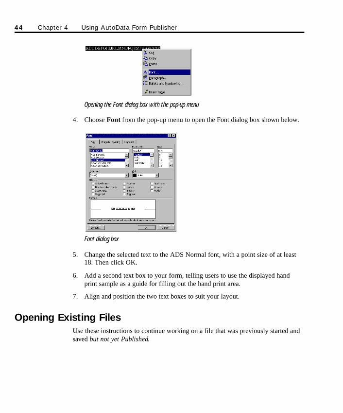
Opening the Font dialog box with the pop-up menu
4. Choose Font from the pop-up menu to open the Font dialog box shown below.
Font dialog box
5. Change the selected text to the ADS Normal font, with a point size of at least18. Then click OK.
6. Add a second text box to your form, telling users to use the displayed handprint sample as a guide for filling out the hand print area.
7. Align and position the two text boxes to suit your layout.
Opening Existing FilesUse these instructions to continue working on a file that was previously started andsaved but not yet Published.
44 Chapter 4 Using AutoData Form Publisher
SO Chapter 4 final.qxd 3/21/00 6:22 PM Page 44
Opening saved, unpublished files
Ø To open a saved, unpublished file:
1. If Form Publisher is already running, save (if appropriate) and close your activedocument.
If Form Publisher is not yet running, start Microsoft Word.
2. Choose Open from the File menu (or, if it’s there, select the file from the MostRecently Used (MRU) list at the bottom of the File menu).
Your form document will load in the Form Publisher window.
Opening and editing Published files Once a form has been Published, the changes you can make to it are extremelylimited. We cannot emphasize too strongly the need to wait until you areabsolutely certain that the form is complete and correct.
The process for opening Published files is essentially the same as the one describedin the previous section, Opening saved, unpublished files.
Ø To open a file that was previously Published:
1. If Form Publisher is already running, save (if appropriate) and close your activedocument.
If Form Publisher is not yet running, start Microsoft Word.
2. Choose Open from the File menu (or, if it’s there, select the file from the MRUlist at the bottom of the File menu).
Form Publisher will display the warning box shown in the following figure.
Warning box displayed when you open a Published form
3. Click OK to open the Published document anyway.
Your form document will load in the Form Publisher window.
If you simply want to print copies of your form, ignore the warning and proceed
Given the very limitedpossibilities open to youin modifying apreviously Publishedform, we encourage youto delay the Publishingof a form until you arecertain it is completeand correct.
Only one AutoDataDocument Template canbe open at a time. Microsoft Wordrecognizes that a formwas created using theAutoData DocumentTemplate and loads thetemplate automaticallywith the file, if it’s notalready running.
Chapter 4 Using AutoData Form Publisher 45
SO Chapter 4 final.qxd 3/21/00 6:22 PM Page 45
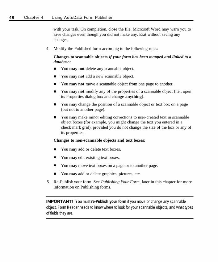
with your task. On completion, close the file. Microsoft Word may warn you tosave changes even though you did not make any. Exit without saving anychanges.
4. Modify the Published form according to the following rules:
Changes to scannable objects if your form has been mapped and linked to adatabase:
n You may not delete any scannable object.
n You may not add a new scannable object.
n You may not move a scannable object from one page to another.
n You may not modify any of the properties of a scannable object (i.e., openits Properties dialog box and change anything).
n You may change the position of a scannable object or text box on a page(but not to another page).
n You may make minor editing corrections to user-created text in scannableobject boxes (for example, you might change the text you entered in acheck mark grid), provided you do not change the size of the box or any ofits properties.
Changes to non-scannable objects and text boxes:
n You may add or delete text boxes.
n You may edit existing text boxes.
n You may move text boxes on a page or to another page.
n You may add or delete graphics, pictures, etc.
5. Re-Publish your form. See Publishing Your Form, later in this chapter for moreinformation on Publishing forms.
IMPORTANT! You must re-Publish your form if you move or change any scannableobject. Form Reader needs to know where to look for your scannable objects, and what typesof fields they are.
46 Chapter 4 Using AutoData Form Publisher
SO Chapter 4 final.qxd 3/21/00 6:22 PM Page 46
Saving FilesIt is advisable to name and save your file as soon as you open a blank form. Doingthis allows you to take full advantage of Word’s Autosave capabilities. Make sureyour saves are set up correctly on the Save tab. Access the Save tab from theOptions dialog box by choosing Options from the Tools menu.
As you define and Publish your form, Form Publisher generates companion filesrequired by Scannable Office’s other modules. To prevent confusion, store eachform (and its related files) in its own folder. If desired, create subfolders from theMy Documents default directory suggested by Microsoft Word.
We suggest that you create a folder called Forms, and then create folders within theForms folder for each new form you create. This will greatly speed up the processof finding previously created forms and simplify saving new ones. Take fulladvantage of Microsoft Windows’ long file name capability, and create file namesthat are meaningful and readily identifiable by you and others who may need towork with your forms.
Ø To save a form:
1. Click the Save button (or choose Save from the File menu, or press CTRL+S)to open the Save dialog box.
2. Navigate to the drive and directory where your file will be stored. If desired,create a new folder for your form.
3. Type a name for your file in the File Name space. Microsoft Word automaticallyadds the .DOC extension.
4. Click Save to save the file in its new location.
Defining Scannable Objects Scannable objects are elements on your form that may be completed by arespondent (the information is stored in your final database or spreadsheet). Theyinclude the six basic field types that were briefly described in the Designing Formschapter, and your form’s Locator marks.
OverviewBefore creating any scannable objects on the blank form page in the Form Publisherwindow, we encourage you to thoroughly familiarize yourself with Chapter 3,
Chapter 4 Using AutoData Form Publisher 47
SO Chapter 4 final.qxd 3/21/00 6:22 PM Page 47
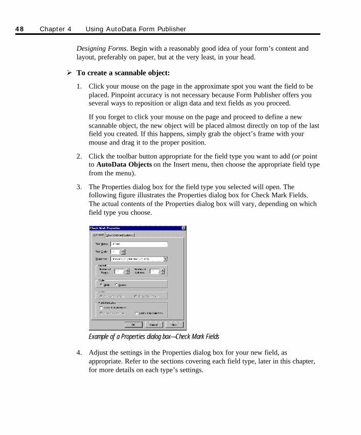
Designing Forms. Begin with a reasonably good idea of your form’s content andlayout, preferably on paper, but at the very least, in your head.
Ø To create a scannable object:
1. Click your mouse on the page in the approximate spot you want the field to beplaced. Pinpoint accuracy is not necessary because Form Publisher offers youseveral ways to reposition or align data and text fields as you proceed.
If you forget to click your mouse on the page and proceed to define a newscannable object, the new object will be placed almost directly on top of the lastfield you created. If this happens, simply grab the object’s frame with yourmouse and drag it to the proper position.
2. Click the toolbar button appropriate for the field type you want to add (or pointto AutoData Objects on the Insert menu, then choose the appropriate field typefrom the menu).
3. The Properties dialog box for the field type you selected will open. Thefollowing figure illustrates the Properties dialog box for Check Mark Fields.The actual contents of the Properties dialog box will vary, depending on whichfield type you choose.
Example of a Properties dialog box—Check Mark Fields
4. Adjust the settings in the Properties dialog box for your new field, asappropriate. Refer to the sections covering each field type, later in this chapter,for more details on each type’s settings.
48 Chapter 4 Using AutoData Form Publisher
SO Chapter 4 final.qxd 3/21/00 6:22 PM Page 48
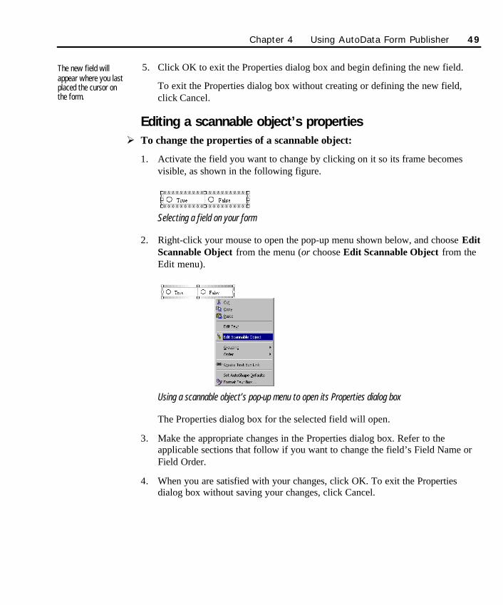
5. Click OK to exit the Properties dialog box and begin defining the new field.
To exit the Properties dialog box without creating or defining the new field,click Cancel.
Editing a scannable object’s propertiesØ To change the properties of a scannable object:
1. Activate the field you want to change by clicking on it so its frame becomesvisible, as shown in the following figure.
Selecting a field on your form
2. Right-click your mouse to open the pop-up menu shown below, and choose EditScannable Object from the menu (or choose Edit Scannable Object from theEdit menu).
Using a scannable object’s pop-up menu to open its Properties dialog box
The Properties dialog box for the selected field will open.
3. Make the appropriate changes in the Properties dialog box. Refer to theapplicable sections that follow if you want to change the field’s Field Name orField Order.
4. When you are satisfied with your changes, click OK. To exit the Propertiesdialog box without saving your changes, click Cancel.
The new field willappear where you lastplaced the cursor onthe form.
Chapter 4 Using AutoData Form Publisher 49
SO Chapter 4 final.qxd 3/21/00 6:22 PM Page 49
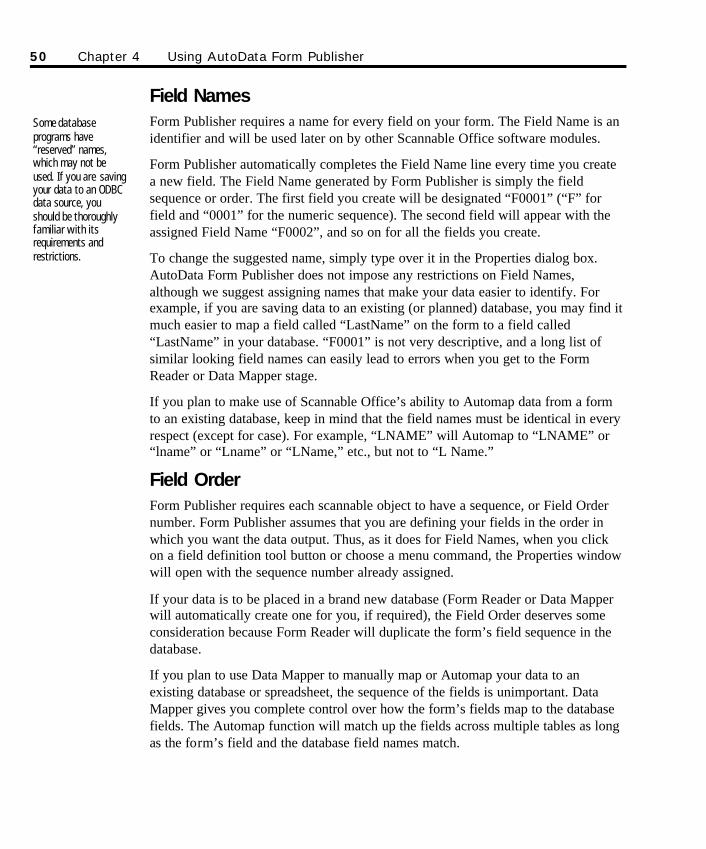
Field NamesForm Publisher requires a name for every field on your form. The Field Name is anidentifier and will be used later on by other Scannable Office software modules.
Form Publisher automatically completes the Field Name line every time you createa new field. The Field Name generated by Form Publisher is simply the fieldsequence or order. The first field you create will be designated “F0001” (“F” forfield and “0001” for the numeric sequence). The second field will appear with theassigned Field Name “F0002”, and so on for all the fields you create.
To change the suggested name, simply type over it in the Properties dialog box.AutoData Form Publisher does not impose any restrictions on Field Names,although we suggest assigning names that make your data easier to identify. Forexample, if you are saving data to an existing (or planned) database, you may find itmuch easier to map a field called “LastName” on the form to a field called“LastName” in your database. “F0001” is not very descriptive, and a long list ofsimilar looking field names can easily lead to errors when you get to the FormReader or Data Mapper stage.
If you plan to make use of Scannable Office’s ability to Automap data from a formto an existing database, keep in mind that the field names must be identical in everyrespect (except for case). For example, “LNAME” will Automap to “LNAME” or“lname” or “Lname” or “LName,” etc., but not to “L Name.”
Field OrderForm Publisher requires each scannable object to have a sequence, or Field Ordernumber. Form Publisher assumes that you are defining your fields in the order inwhich you want the data output. Thus, as it does for Field Names, when you clickon a field definition tool button or choose a menu command, the Properties windowwill open with the sequence number already assigned.
If your data is to be placed in a brand new database (Form Reader or Data Mapperwill automatically create one for you, if required), the Field Order deserves someconsideration because Form Reader will duplicate the form’s field sequence in thedatabase.
If you plan to use Data Mapper to manually map or Automap your data to anexisting database or spreadsheet, the sequence of the fields is unimportant. DataMapper gives you complete control over how the form’s fields map to the databasefields. The Automap function will match up the fields across multiple tables as longas the form’s field and the database field names match.
Some databaseprograms have“reserved” names,which may not beused. If you are savingyour data to an ODBCdata source, youshould be thoroughlyfamiliar with itsrequirements andrestrictions.
50 Chapter 4 Using AutoData Form Publisher
SO Chapter 4 final.qxd 3/21/00 6:22 PM Page 50
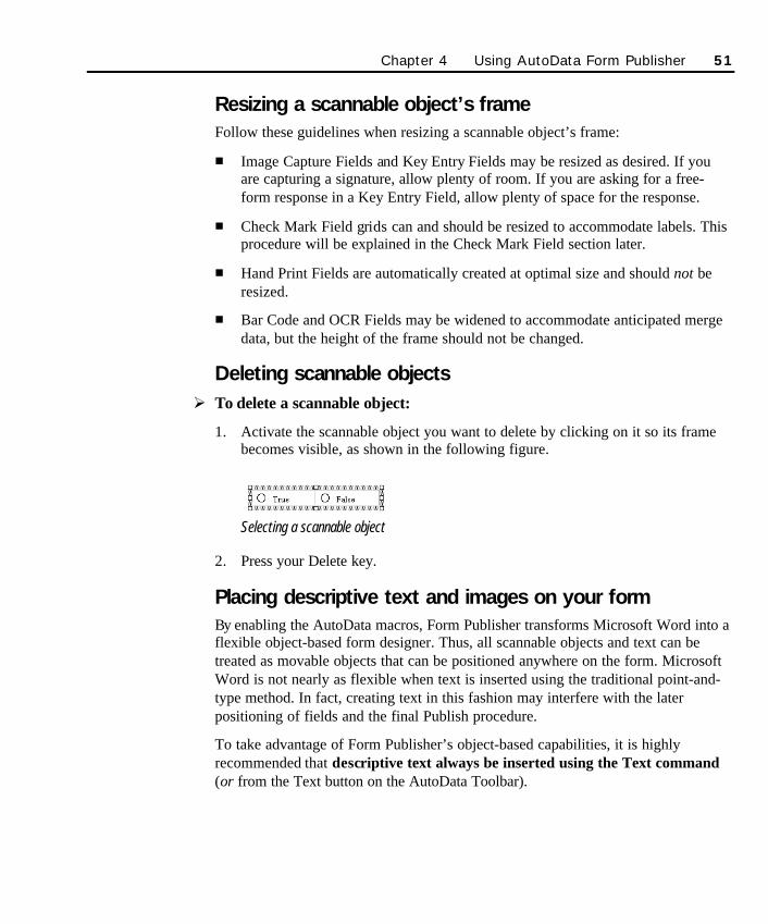
Resizing a scannable object’s frame Follow these guidelines when resizing a scannable object’s frame:
n Image Capture Fields and Key Entry Fields may be resized as desired. If youare capturing a signature, allow plenty of room. If you are asking for a free-form response in a Key Entry Field, allow plenty of space for the response.
n Check Mark Field grids can and should be resized to accommodate labels. Thisprocedure will be explained in the Check Mark Field section later.
n Hand Print Fields are automatically created at optimal size and should not beresized.
n Bar Code and OCR Fields may be widened to accommodate anticipated mergedata, but the height of the frame should not be changed.
Deleting scannable objectsØ To delete a scannable object:
1. Activate the scannable object you want to delete by clicking on it so its framebecomes visible, as shown in the following figure.
Selecting a scannable object
2. Press your Delete key.
Placing descriptive text and images on your formBy enabling the AutoData macros, Form Publisher transforms Microsoft Word into aflexible object-based form designer. Thus, all scannable objects and text can betreated as movable objects that can be positioned anywhere on the form. MicrosoftWord is not nearly as flexible when text is inserted using the traditional point-and-type method. In fact, creating text in this fashion may interfere with the laterpositioning of fields and the final Publish procedure.
To take advantage of Form Publisher’s object-based capabilities, it is highlyrecommended that descriptive text always be inserted using the Text command(or from the Text button on the AutoData Toolbar).
Chapter 4 Using AutoData Form Publisher 51
SO Chapter 4 final.qxd 3/21/00 6:22 PM Page 51
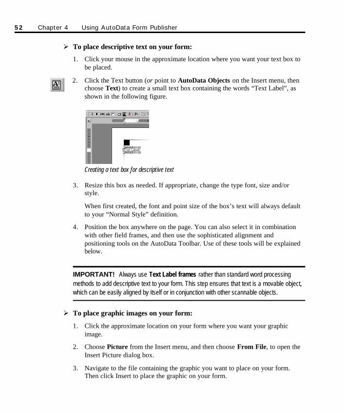
Ø To place descriptive text on your form:
1. Click your mouse in the approximate location where you want your text box tobe placed.
2. Click the Text button (or point to AutoData Objects on the Insert menu, thenchoose Text) to create a small text box containing the words “Text Label”, asshown in the following figure.
Creating a text box for descriptive text
3. Resize this box as needed. If appropriate, change the type font, size and/orstyle.
When first created, the font and point size of the box’s text will always defaultto your “Normal Style” definition.
4. Position the box anywhere on the page. You can also select it in combinationwith other field frames, and then use the sophisticated alignment andpositioning tools on the AutoData Toolbar. Use of these tools will be explainedbelow.
IMPORTANT! Always use Text Label frames rather than standard word processingmethods to add descriptive text to your form. This step ensures that text is a movable object,which can be easily aligned by itself or in conjunction with other scannable objects.
Ø To place graphic images on your form:
1. Click the approximate location on your form where you want your graphicimage.
2. Choose Picture from the Insert menu, and then choose From File, to open theInsert Picture dialog box.
3. Navigate to the file containing the graphic you want to place on your form.Then click Insert to place the graphic on your form.
52 Chapter 4 Using AutoData Form Publisher
SO Chapter 4 final.qxd 3/21/00 6:22 PM Page 52
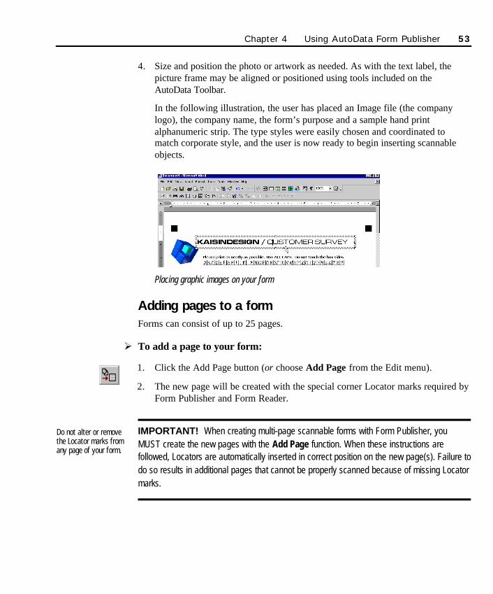
4. Size and position the photo or artwork as needed. As with the text label, thepicture frame may be aligned or positioned using tools included on theAutoData Toolbar.
In the following illustration, the user has placed an Image file (the companylogo), the company name, the form’s purpose and a sample hand printalphanumeric strip. The type styles were easily chosen and coordinated tomatch corporate style, and the user is now ready to begin inserting scannableobjects.
Placing graphic images on your form
Adding pages to a formForms can consist of up to 25 pages.
Ø To add a page to your form:
1. Click the Add Page button (or choose Add Page from the Edit menu).
2. The new page will be created with the special corner Locator marks required byForm Publisher and Form Reader.
IMPORTANT! When creating multi-page scannable forms with Form Publisher, youMUST create the new pages with the Add Page function. When these instructions arefollowed, Locators are automatically inserted in correct position on the new page(s). Failure todo so results in additional pages that cannot be properly scanned because of missing Locatormarks.
Do not alter or removethe Locator marks fromany page of your form.
Chapter 4 Using AutoData Form Publisher 53
SO Chapter 4 final.qxd 3/21/00 6:22 PM Page 53
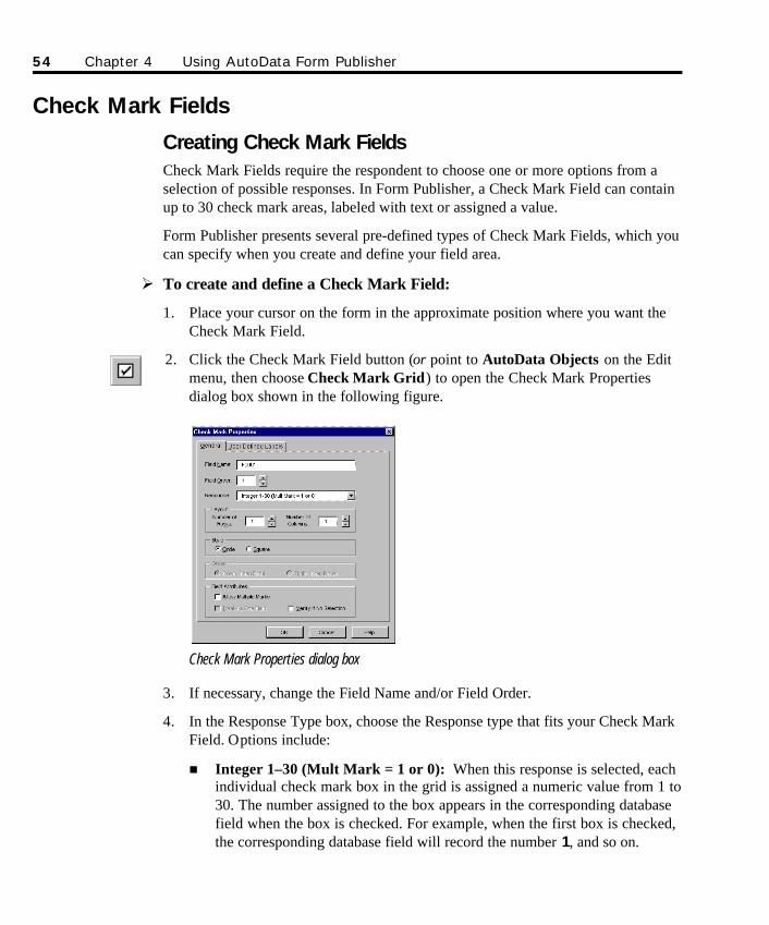
Check Mark Fields
Creating Check Mark Fields Check Mark Fields require the respondent to choose one or more options from aselection of possible responses. In Form Publisher, a Check Mark Field can containup to 30 check mark areas, labeled with text or assigned a value.
Form Publisher presents several pre-defined types of Check Mark Fields, which youcan specify when you create and define your field area.
Ø To create and define a Check Mark Field:
1. Place your cursor on the form in the approximate position where you want theCheck Mark Field.
2. Click the Check Mark Field button (or point to AutoData Objects on the Editmenu, then choose Check Mark Grid) to open the Check Mark Propertiesdialog box shown in the following figure.
Check Mark Properties dialog box
3. If necessary, change the Field Name and/or Field Order.
4. In the Response Type box, choose the Response type that fits your Check MarkField. Options include:
n Integer 1–30 (Mult Mark = 1 or 0): When this response is selected, eachindividual check mark box in the grid is assigned a numeric value from 1 to30. The number assigned to the box appears in the corresponding databasefield when the box is checked. For example, when the first box is checked,the corresponding database field will record the number 1, and so on.
54 Chapter 4 Using AutoData Form Publisher
SO Chapter 4 final.qxd 3/21/00 6:22 PM Page 54

A maximum of 30 individual check boxes is imposed for this responsetype. When choosing this response type, remember to specify acombination of rows and columns sufficient to handle the numbers youwant to use, expanding the grid size as necessary.
n Alpha Value (A–Z): When this response type is selected, Form Publisherassigns each of the check mark boxes in the field its own letter. The letterassigned to the box is the value returned in the corresponding database fieldwhen the box is checked. For example, when the first box is checked, thecorresponding database field will record the letter A. When the second boxis checked, the corresponding database field will record the letter B, and soon. When you use the Alpha Value response type, the field is limited to a maxi-mum of 26 individual check boxes. Remember to specify a combination ofrows and columns sufficient to handle the number of letters you want touse, expanding the grid as necessary. If, for example, you specify threerows and three columns, the grid will have 9 check mark boxes labeled “A”to “I”.
n Yes or No (Y/N): Use this response type on a Check Mark Field with twoboxes, labeled Yes or No. The corresponding database field will display a Ywhen the Yes box is checked, and an N when the No box is checked.Remember to specify either two columns or two rows for the field.
n Yes or No or Other (Y/N/O): Use this response type on a Check MarkField with three boxes, labeled Yes, No and Other. The corresponding data -base field will display a Y if the Yes box is checked, an N if the No box ischecked, and an O if the Other box is checked. Remember to specify eitherthree columns or three rows for the field.
n True or False: Use this response type on a Check Mark Field with twoboxes, labeled True and False. If the True box is checked, the correspondingdatabase field will display a T. If the False box is checked, the correspon-ding database field will display an F. Remember to specify either twocolumns or two rows for the field.
n True or False or Other (T/F/O): Use this response type on a Check MarkField with three boxes, labeled True, False and Other. If the True box ischecked, the corresponding database field will display a T. If the False boxis checked, the corresponding database field will display an F. If the Otherbox is checked, the corresponding database field will display an O.Remember to specify either three columns or three rows for the field.
Chapter 4 Using AutoData Form Publisher 55
SO Chapter 4 final.qxd 3/21/00 6:22 PM Page 55
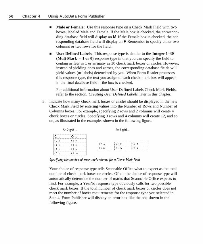
n Male or Female: Use this response type on a Check Mark Field with twoboxes, labeled Male and Female. If the Male box is checked, the correspon-ding database field will display an M. If the Female box is checked, the cor-responding database field will display an F. Remember to specify either twocolumns or two rows for the field.
n User Defined Labels: This response type is similar to the Integer 1–30(Mult Mark = 1 or 0) response type in that you can specify the field tocontain as few as 1 or as many as 30 check mark boxes or circles. However,instead of yielding ones and zeroes, the corresponding database fields willyield values (or labels) determined by you. When Form Reader processesthis response type, the text you assign to each check mark box will appearin the final database field if the box is checked.
For additional information about User Defined Labels Check Mark Fields,refer to the section, Creating User Defined Labels, later in this chapter.
5. Indicate how many check mark boxes or circles should be displayed in the newCheck Mark Field by entering values into the Number of Rows and Number ofColumns boxes. For example, specifying 2 rows and 2 columns will create 4check boxes or circles. Specifying 3 rows and 4 columns will create 12, and soon, as illustrated in the examples shown in the following figure.
Specifying the number of rows and columns for a Check Mark Field
Your choice of response type tells Scannable Office what to expect as the totalnumber of check mark boxes or circles. Often, the choice of response type willautomatically determine the number of marks that Scannable Office expects tofind. For example, a Yes/No response type obviously calls for two possiblecheck mark boxes. If the total number of check mark boxes or circles does notmeet the number of boxes requirements for the response type you selected inStep 4, Form Publisher will display an error box like the one shown in thefollowing figure.
56 Chapter 4 Using AutoData Form Publisher
5×2 grid ... 2×3 grid ...
SO Chapter 4 final.qxd 3/21/00 6:22 PM Page 56
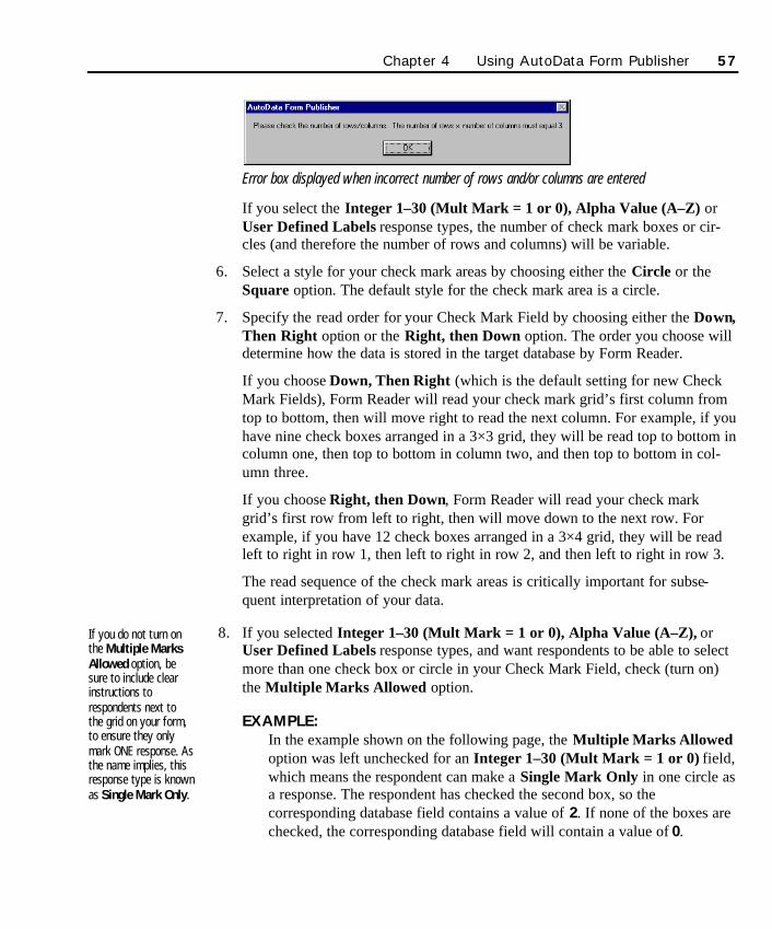
Error box displayed when incorrect number of rows and/or columns are entered
If you select the Integer 1–30 (Mult Mark = 1 or 0), Alpha Value (A–Z) orUser Defined Labels response types, the number of check mark boxes or cir-cles (and therefore the number of rows and columns) will be variable.
6. Select a style for your check mark areas by choosing either the Circle or theSquare option. The default style for the check mark area is a circle.
7. Specify the read order for your Check Mark Field by choosing either the Down,Then Right option or the Right, then Down option. The order you choose willdetermine how the data is stored in the target database by Form Reader.
If you choose Down, Then Right (which is the default setting for new CheckMark Fields), Form Reader will read your check mark grid’s first column fromtop to bottom, then will move right to read the next column. For example, if youhave nine check boxes arranged in a 3×3 grid, they will be read top to bottom incolumn one, then top to bottom in column two, and then top to bottom in col-umn three.
If you choose Right, then Down, Form Reader will read your check markgrid’s first row from left to right, then will move down to the next row. Forexample, if you have 12 check boxes arranged in a 3×4 grid, they will be readleft to right in row 1, then left to right in row 2, and then left to right in row 3.
The read sequence of the check mark areas is critically important for subse-quent interpretation of your data.
8. If you selected Integer 1–30 (Mult Mark = 1 or 0), Alpha Value (A–Z), orUser Defined Labels response types, and want respondents to be able to selectmore than one check box or circle in your Check Mark Field, check (turn on)the Multiple Marks Allowed option.
EXAMPLE:In the example shown on the following page, the Multiple Marks Allowedoption was left unchecked for an Integer 1–30 (Mult Mark = 1 or 0) field,which means the respondent can make a Single Mark Only in one circle asa response. The respondent has checked the second box, so thecorresponding database field contains a value of 2. If none of the boxes arechecked, the corresponding database field will contain a value of 0.
If you do not turn onthe Multiple MarksAllowed option, besure to include clearinstructions torespondents next tothe grid on your form,to ensure they onlymark ONE response. Asthe name implies, thisresponse type is knownas Single Mark Only.
Chapter 4 Using AutoData Form Publisher 57
SO Chapter 4 final.qxd 3/21/00 6:22 PM Page 57
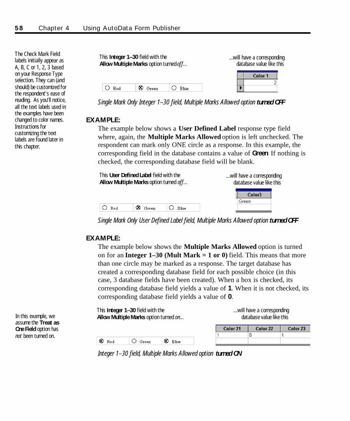
Single Mark Only Integer 1–30 field, Multiple Marks Allowed option turned OFF
EXAMPLE:The example below shows a User Defined Label response type fieldwhere, again, the Multiple Marks Allowed option is left unchecked. Therespondent can mark only ONE circle as a response. In this example, thecorresponding field in the database contains a value of Green. If nothing ischecked, the corresponding database field will be blank.
Single Mark Only User Defined Label field, Multiple Marks Allowed option turned OFF
EXAMPLE:The example below shows the Multiple Marks Allowed option is turnedon for an Integer 1–30 (Mult Mark = 1 or 0) field. This means that morethan one circle may be marked as a response. The target database hascreated a corresponding database field for each possible choice (in thiscase, 3 database fields have been created). When a box is checked, itscorresponding database field yields a value of 1. When it is not checked, itscorresponding database field yields a value of 0.
Integer 1–30 field, Multiple Marks Allowed option turned ON
58 Chapter 4 Using AutoData Form Publisher
This Integer 1–30 field with the Allow Multiple Marks option turned off...
...will have a correspondingdatabase value like this
This User Defined Label field with theAllow Multiple Marks option turned off...
...will have a correspondingdatabase value like this
This Integer 1–30 field with the Allow Multiple Marks option turned on...
...will have a correspondingdatabase value like thisIn this example, we
assume the Treat asOne Field option hasnot been turned on.
The Check Mark Fieldlabels initially appear asA, B, C or 1, 2, 3 basedon your Response Typeselection. They can (andshould) be customized forthe respondent’s ease ofreading. As you’ll notice,all the text labels used inthe examples have beenchanged to color names.Instructions forcustomizing the textlabels are found later inthis chapter.
SO Chapter 4 final.qxd 3/21/00 6:22 PM Page 58
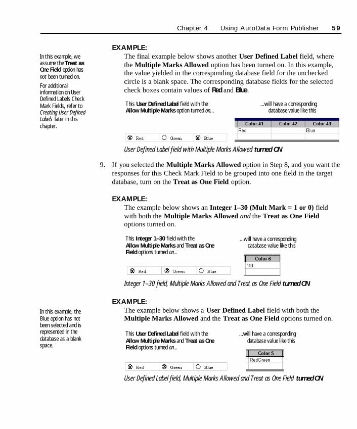
EXAMPLE:The final example below shows another User Defined Label field, wherethe Multiple Marks Allowed option has been turned on. In this example,the value yielded in the corresponding database field for the uncheckedcircle is a blank space. The corresponding database fields for the selectedcheck boxes contain values of Red and Blue.
User Defined Label field with Multiple Marks Allowed turned ON
9. If you selected the Multiple Marks Allowed option in Step 8, and you want theresponses for this Check Mark Field to be grouped into one field in the targetdatabase, turn on the Treat as One Field option.
EXAMPLE:The example below shows an Integer 1–30 (Mult Mark = 1 or 0) fieldwith both the Multiple Marks Allowed and the Treat as One Fieldoptions turned on.
Integer 1–30 field, Multiple Marks Allowed and Treat as One Field turned ON
EXAMPLE:The example below shows a User Defined Label field with both theMultiple Marks Allowed and the Treat as One Field options turned on.
User Defined Label field, Multiple Marks Allowed and Treat as One Field turned ON
Chapter 4 Using AutoData Form Publisher 59
This User Defined Label field with theAllow Multiple Marks option turned on...
...will have a correspondingdatabase value like this
This Integer 1–30 field with the Allow Multiple Marks and Treat as OneField options turned on...
...will have a correspondingdatabase value like this
This User Defined Label field with theAllow Multiple Marks and Treat as OneField options turned on...
...will have a correspondingdatabase value like this
In this example, weassume the Treat asOne Field option hasnot been turned on.For additionalinformation on UserDefined Labels CheckMark Fields, refer toCreating User DefinedLabels later in thischapter.
In this example, theBlue option has notbeen selected and isrepresented in thedatabase as a blankspace.
SO Chapter 4 final.qxd 3/21/00 6:22 PM Page 59
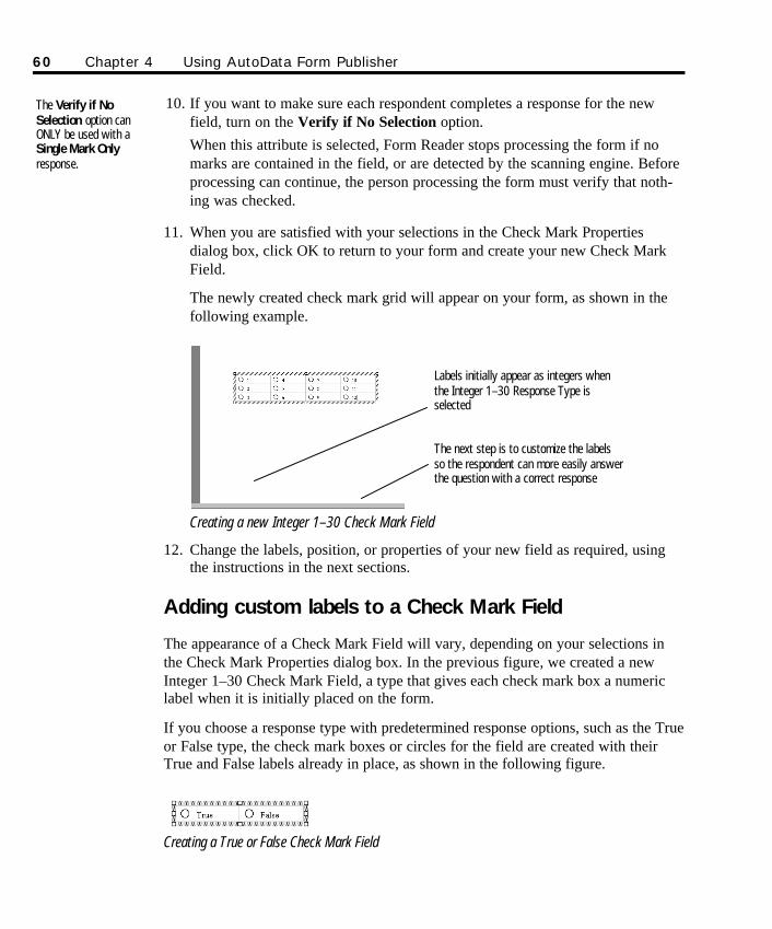
10. If you want to make sure each respondent completes a response for the newfield, turn on the Verify if No Selection option. When this attribute is selected, Form Reader stops processing the form if nomarks are contained in the field, or are detected by the scanning engine. Beforeprocessing can continue, the person processing the form must verify that noth-ing was checked.
11. When you are satisfied with your selections in the Check Mark Propertiesdialog box, click OK to return to your form and create your new Check MarkField.
The newly created check mark grid will appear on your form, as shown in thefollowing example.
Creating a new Integer 1–30 Check Mark Field
12. Change the labels, position, or properties of your new field as required, usingthe instructions in the next sections.
Adding custom labels to a Check Mark Field
The appearance of a Check Mark Field will vary, depending on your selections inthe Check Mark Properties dialog box. In the previous figure, we created a newInteger 1–30 Check Mark Field, a type that gives each check mark box a numericlabel when it is initially placed on the form.
If you choose a response type with predetermined response options, such as the Trueor False type, the check mark boxes or circles for the field are created with theirTrue and False labels already in place, as shown in the following figure.
Creating a True or False Check Mark Field
The Verify if NoSelection option canONLY be used with aSingle Mark Onlyresponse.
60 Chapter 4 Using AutoData Form Publisher
Labels initially appear as integers whenthe Integer 1–30 Response Type isselected
The next step is to customize the labelsso the respondent can more easily answerthe question with a correct response
SO Chapter 4 final.qxd 3/21/00 6:22 PM Page 60
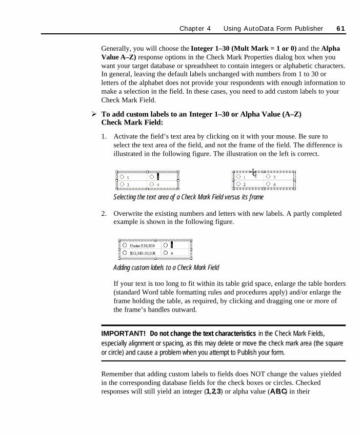
Generally, you will choose the Integer 1–30 (Mult Mark = 1 or 0) and the AlphaValue A–Z) response options in the Check Mark Properties dialog box when youwant your target database or spreadsheet to contain integers or alphabetic characters.In general, leaving the default labels unchanged with numbers from 1 to 30 orletters of the alphabet does not provide your respondents with enough information tomake a selection in the field. In these cases, you need to add custom labels to yourCheck Mark Field.
Ø To add custom labels to an Integer 1–30 or Alpha Value (A–Z) Check Mark Field:
1. Activate the field’s text area by clicking on it with your mouse. Be sure toselect the text area of the field, and not the frame of the field. The difference isillustrated in the following figure. The illustration on the left is correct.
Selecting the text area of a Check Mark Field versus its frame
2. Overwrite the existing numbers and letters with new labels. A partly completedexample is shown in the following figure.
Adding custom labels to a Check Mark Field
If your text is too long to fit within its table grid space, enlarge the table borders(standard Word table formatting rules and procedures apply) and/or enlarge theframe holding the table, as required, by clicking and dragging one or more ofthe frame’s handles outward.
IMPORTANT! Do not change the text characteristics in the Check Mark Fields,especially alignment or spacing, as this may delete or move the check mark area (the squareor circle) and cause a problem when you attempt to Publish your form.
Remember that adding custom labels to fields does NOT change the values yieldedin the corresponding database fields for the check boxes or circles. Checkedresponses will still yield an integer (1,2,3) or alpha value (A,B,C) in their
Chapter 4 Using AutoData Form Publisher 61
SO Chapter 4 final.qxd 3/21/00 6:22 PM Page 61
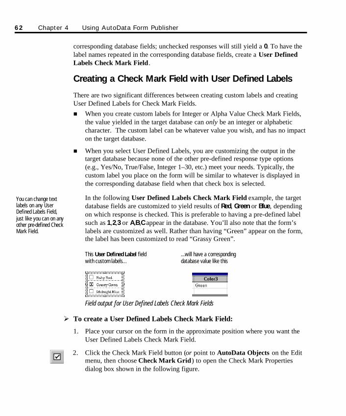
corresponding database fields; unchecked responses will still yield a 0. To have thelabel names repeated in the corresponding database fields, create a User DefinedLabels Check Mark Field.
Creating a Check Mark Field with User Defined Labels
There are two significant differences between creating custom labels and creatingUser Defined Labels for Check Mark Fields. n When you create custom labels for Integer or Alpha Value Check Mark Fields,
the value yielded in the target database can only be an integer or alphabeticcharacter. The custom label can be whatever value you wish, and has no impacton the target database.
n When you select User Defined Labels, you are customizing the output in thetarget database because none of the other pre-defined response type options(e.g., Yes/No, True/False, Integer 1–30, etc.) meet your needs. Typically, thecustom label you place on the form will be similar to whatever is displayed inthe corresponding database field when that check box is selected.
In the following User Defined Labels Check Mark Field example, the targetdatabase fields are customized to yield results of Red, Green or Blue, dependingon which response is checked. This is preferable to having a pre-defined labelsuch as 1,2,3 or A,B,C appear in the database. You’ll also note that the form’slabels are customized as well. Rather than having “Green” appear on the form,the label has been customized to read “Grassy Green”.
Field output for User Defined Labels Check Mark Fields
Ø To create a User Defined Labels Check Mark Field:
1. Place your cursor on the form in the approximate position where you want theUser Defined Labels Check Mark Field.
2. Click the Check Mark Field button (or point to AutoData Objects on the Editmenu, then choose Check Mark Grid) to open the Check Mark Propertiesdialog box shown in the following figure.
You can change textlabels on any UserDefined Labels Field,just like you can on anyother pre-defined CheckMark Field.
62 Chapter 4 Using AutoData Form Publisher
This User Defined Label fieldwith custom labels...
...will have a correspondingdatabase value like this
SO Chapter 4 final.qxd 3/21/00 6:22 PM Page 62
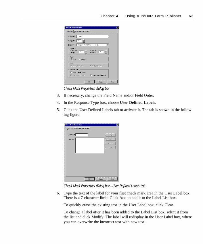
Check Mark Properties dialog box
3. If necessary, change the Field Name and/or Field Order.
4. In the Response Type box, choose User Defined Labels.
5. Click the User Defined Labels tab to activate it. The tab is shown in the follow-ing figure.
Check Mark Properties dialog box—User Defined Labels tab
6. Type the text of the label for your first check mark area in the User Label box.There is a 7-character limit. Click Add to add it to the Label List box.
To quickly erase the existing text in the User Label box, click Clear.
To change a label after it has been added to the Label List box, select it fromthe list and click Modify. The label will redisplay in the User Label box, whereyou can overwrite the incorrect text with new text.
Chapter 4 Using AutoData Form Publisher 63
SO Chapter 4 final.qxd 3/21/00 6:22 PM Page 63
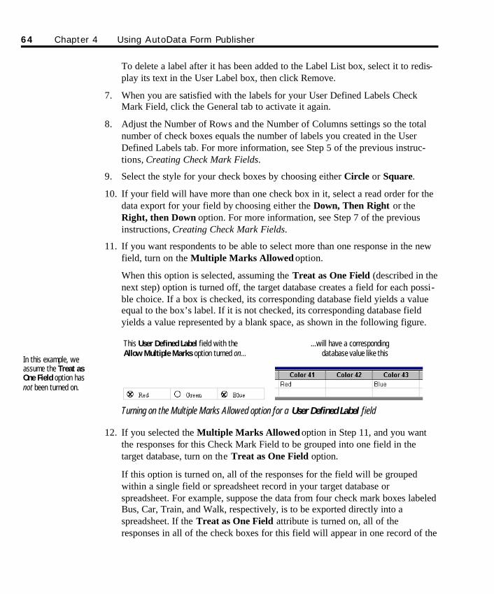
To delete a label after it has been added to the Label List box, select it to redis-play its text in the User Label box, then click Remove.
7. When you are satisfied with the labels for your User Defined Labels CheckMark Field, click the General tab to activate it again.
8. Adjust the Number of Rows and the Number of Columns settings so the totalnumber of check boxes equals the number of labels you created in the UserDefined Labels tab. For more information, see Step 5 of the previous instruc-tions, Creating Check Mark Fields.
9. Select the style for your check boxes by choosing either Circle or Square.
10. If your field will have more than one check box in it, select a read order for thedata export for your field by choosing either the Down, Then Right or theRight, then Down option. For more information, see Step 7 of the previousinstructions, Creating Check Mark Fields.
11. If you want respondents to be able to select more than one response in the newfield, turn on the Multiple Marks Allowed option.
When this option is selected, assuming the Treat as One Field (described in thenext step) option is turned off, the target database creates a field for each possi-ble choice. If a box is checked, its corresponding database field yields a valueequal to the box’s label. If it is not checked, its corresponding database fieldyields a value represented by a blank space, as shown in the following figure.
Turning on the Multiple Marks Allowed option for a User Defined Label field
12. If you selected the Multiple Marks Allowed option in Step 11, and you wantthe responses for this Check Mark Field to be grouped into one field in thetarget database, turn on the Treat as One Field option.
If this option is turned on, all of the responses for the field will be groupedwithin a single field or spreadsheet record in your target database orspreadsheet. For example, suppose the data from four check mark boxes labeledBus, Car, Train, and Walk, respectively, is to be exported directly into aspreadsheet. If the Treat as One Field attribute is turned on, all of theresponses in all of the check boxes for this field will appear in one record of the
64 Chapter 4 Using AutoData Form Publisher
This User Defined Label field with theAllow Multiple Marks option turned on...
...will have a correspondingdatabase value like this
In this example, weassume the Treat asOne Field option hasnot been turned on.
SO Chapter 4 final.qxd 3/21/00 6:22 PM Page 64
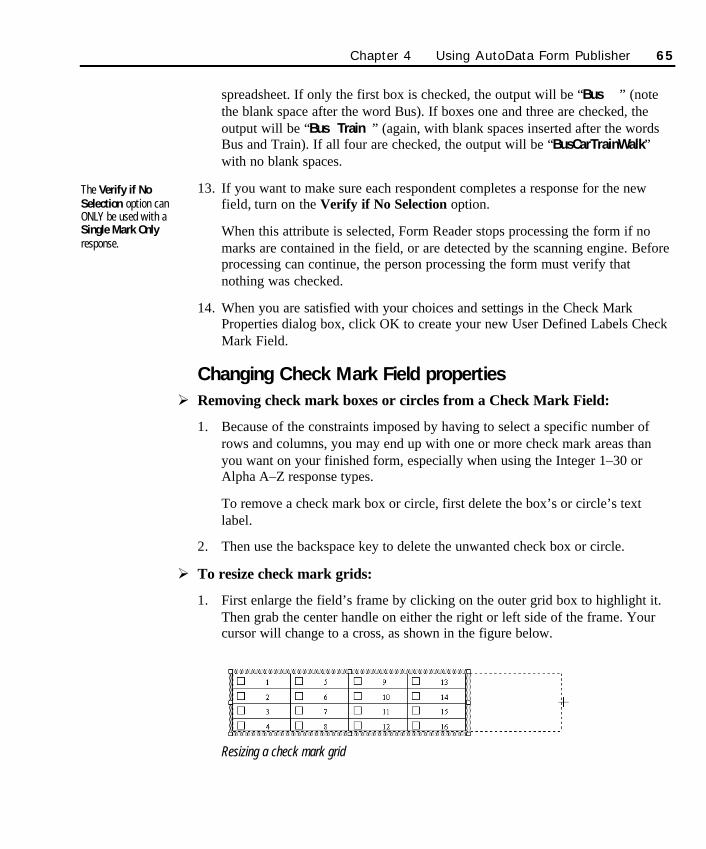
Chapter 4 Using AutoData Form Publisher 65
spreadsheet. If only the first box is checked, the output will be “Bus ” (notethe blank space after the word Bus). If boxes one and three are checked, theoutput will be “Bus Train ” (again, with blank spaces inserted after the wordsBus and Train). If all four are checked, the output will be “BusCarTrainWalk”with no blank spaces.
13. If you want to make sure each respondent completes a response for the newfield, turn on the Verify if No Selection option.
When this attribute is selected, Form Reader stops processing the form if nomarks are contained in the field, or are detected by the scanning engine. Beforeprocessing can continue, the person processing the form must verify thatnothing was checked.
14. When you are satisfied with your choices and settings in the Check MarkProperties dialog box, click OK to create your new User Defined Labels CheckMark Field.
Changing Check Mark Field propertiesØ Removing check mark boxes or circles from a Check Mark Field:
1. Because of the constraints imposed by having to select a specific number ofrows and columns, you may end up with one or more check mark areas thanyou want on your finished form, especially when using the Integer 1–30 orAlpha A–Z response types.
To remove a check mark box or circle, first delete the box’s or circle’s textlabel.
2. Then use the backspace key to delete the unwanted check box or circle.
Ø To resize check mark grids:
1. First enlarge the field’s frame by clicking on the outer grid box to highlight it.Then grab the center handle on either the right or left side of the frame. Yourcursor will change to a cross, as shown in the figure below.
Resizing a check mark grid
The Verify if NoSelection option canONLY be used with aSingle Mark Onlyresponse.
SO Chapter 4 final.qxd 3/21/00 6:22 PM Page 65
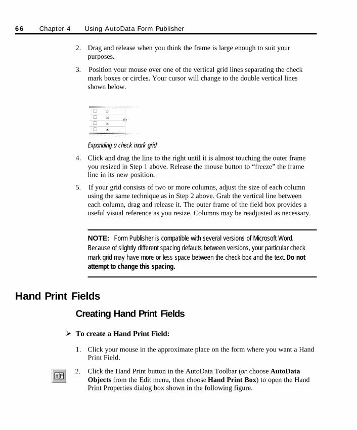
2. Drag and release when you think the frame is large enough to suit yourpurposes.
3. Position your mouse over one of the vertical grid lines separating the checkmark boxes or circles. Your cursor will change to the double vertical linesshown below.
Expanding a check mark grid
4. Click and drag the line to the right until it is almost touching the outer frameyou resized in Step 1 above. Release the mouse button to “freeze” the frameline in its new position.
5. If your grid consists of two or more columns, adjust the size of each columnusing the same technique as in Step 2 above. Grab the vertical line betweeneach column, drag and release it. The outer frame of the field box provides auseful visual reference as you resize. Columns may be readjusted as necessary.
NOTE: Form Publisher is compatible with several versions of Microsoft Word.Because of slightly different spacing defaults between versions, your particular checkmark grid may have more or less space between the check box and the text. Do notattempt to change this spacing.
Hand Print Fields
Creating Hand Print Fields
Ø To create a Hand Print Field:
1. Click your mouse in the approximate place on the form where you want a HandPrint Field.
2. Click the Hand Print button in the AutoData Toolbar (or choose AutoDataObjects from the Edit menu, then choose Hand Print Box) to open the HandPrint Properties dialog box shown in the following figure.
66 Chapter 4 Using AutoData Form Publisher
SO Chapter 4 final.qxd 3/21/00 6:22 PM Page 66
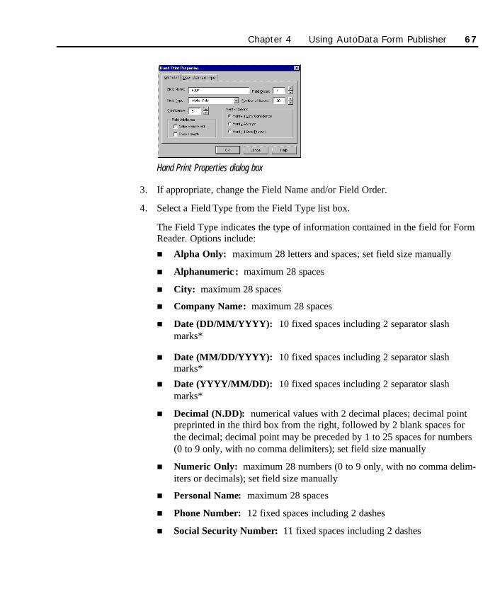
Hand Print Properties dialog box
3. If appropriate, change the Field Name and/or Field Order.
4. Select a Field Type from the Field Type list box.
The Field Type indicates the type of information contained in the field for FormReader. Options include:
n Alpha Only: maximum 28 letters and spaces; set field size manually
n Alphanumeric : maximum 28 spaces
n City: maximum 28 spaces
n Company Name: maximum 28 spaces
n Date (DD/MM/YYYY): 10 fixed spaces including 2 separator slashmarks*
n Date (MM/DD/YYYY): 10 fixed spaces including 2 separator slashmarks*
n Date (YYYY/MM/DD): 10 fixed spaces including 2 separator slashmarks*
n Decimal (N.DD): numerical values with 2 decimal places; decimal pointpreprinted in the third box from the right, followed by 2 blank spaces forthe decimal; decimal point may be preceded by 1 to 25 spaces for numbers(0 to 9 only, with no comma delimiters); set field size manually
n Numeric Only: maximum 28 numbers (0 to 9 only, with no comma delim-iters or decimals); set field size manually
n Personal Name: maximum 28 spaces
n Phone Number: 12 fixed spaces including 2 dashes
n Social Security Number: 11 fixed spaces including 2 dashes
Chapter 4 Using AutoData Form Publisher 67
SO Chapter 4 final.qxd 3/21/00 6:22 PM Page 67
n State (XX): fixed 2-letter abbreviation; valid state fields include the 50states, the District of Columbia (DC) and Puerto Rico (PR)
n Street Address: Keep in mind the following rules:
a) a blank box must separate the house and/or apartment number from the street name
b) use normal suffixes after street names that are numbers (e.g., 90TH, 91ST, 92ND); do not put a space between the number and the suffix
c) separate the street designations (e.g., AVE, ST, RD, LN, etc.) fromstreet names by a blank box
d) Post Office boxes can be designated in any one of three ways: PO BOX 123, BOX 123, or FOB 123
e) place a blank box between PO and BOX, and another between the letters and numbers; set Number of Boxes manually with a maximumof 28 spaces
n Time (HH:MM:SS) 12 hour format: 8 spaces including 2 separatorcolons**
n Time (HH:MM:SS) 24 hour format: 8 spaces including 2 separatorcolons**
n User Defined Type: maximum 28 spaces; see Creating a User DefinedHand Print Field for details on creating this field type
n Zip Code: field size value automatically adjusts to 5 for this field; to capture a 9-digit zip code (ZIP+4), select either the Numeric Only (create a 9-box field with no dash separating the last 4 digits) or a User Defined Field Type (create a 10-box field with a dash separating thelast 4 digits)
*All three Date fields default to a 4-digit year format. Change the number of spaces in the Properties dialog boxfrom the default 10 to 8 if you want to use a 2-digit year format. The year space on your Date field will be twospaces when it appears on your form.
**If you do not require seconds to be recorded in a Time field, change the number of spaces in the Properties dialogbox from the default 8 (HH:MM:SS) to 5. The Time field will now be placed on the form page in an HH:MM format.
68 Chapter 4 Using AutoData Form Publisher
SO Chapter 4 final.qxd 3/21/00 6:22 PM Page 68

Hand Print Field Min. Max.Field Type Characteristics Boxes Boxes
Alpha Only Alphabetic only 1 28Alphanumeric Mixed alphanumeric 1 28
City Alphanumeric 1 28
Date (all formats) 10 Fixed spaces, including 2 separator slash marks 8 10Decimal (N.DD) Numeric, including decimal point and 2-digit decimal 4 28
Numeric Only Whole numbers only 1 28Personal Name Alphabetic 1 28
Phone Number 12 Fixed Spaces, including 2 dashes 12 12
Social Security 11 Fixed numeric spaces including 2 dashes 11 11State (XX) 2 Fixed alphabetic spaces 2 2
Street Address Alphanumeric, see text for additional rules 1 28Time (all formats) 8 (5 adjusted) Fixed spaces, including 2 colons 5 8
User Defined Type Alphanumeric, see text for additional rules 1 28
Zip Code (5 digit) 5 Fixed numeric spaces 5 5Zip Code (9 digit) Use Numeric Only with 9 fixed spaces and no dashes 9-10 9-10
or use User Defined Type with 10 fixed spaces, including 1 dash
Chapter 4 Using AutoData Form Publisher 69
SO Chapter 4 final.qxd 3/21/00 6:22 PM Page 69
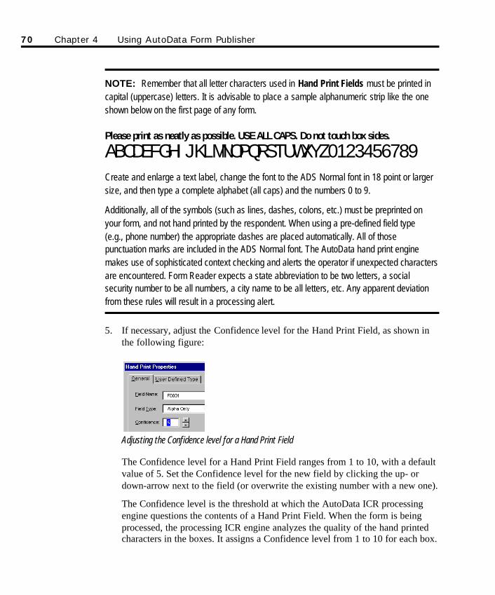
NOTE: Remember that all letter characters used in Hand Print Fields must be printed incapital (uppercase) letters. It is advisable to place a sample alphanumeric strip like the oneshown below on the first page of any form.
Please print as neatly as possible. USE ALL CAPS. Do not touch box sides.
ABCDEFGHIJKLMNOPQRSTUWXYZ0123456789Create and enlarge a text label, change the font to the ADS Normal font in 18 point or largersize, and then type a complete alphabet (all caps) and the numbers 0 to 9.
Additionally, all of the symbols (such as lines, dashes, colons, etc.) must be preprinted onyour form, and not hand printed by the respondent. When using a pre-defined field type (e.g., phone number) the appropriate dashes are placed automatically. All of thosepunctuation marks are included in the ADS Normal font. The AutoData hand print enginemakes use of sophisticated context checking and alerts the operator if unexpected charactersare encountered. Form Reader expects a state abbreviation to be two letters, a socialsecurity number to be all numbers, a city name to be all letters, etc. Any apparent deviationfrom these rules will result in a processing alert.
5. If necessary, adjust the Confidence level for the Hand Print Field, as shown inthe following figure:
Adjusting the Confidence level for a Hand Print Field
The Confidence level for a Hand Print Field ranges from 1 to 10, with a defaultvalue of 5. Set the Confidence level for the new field by clicking the up- ordown-arrow next to the field (or overwrite the existing number with a new one).
The Confidence level is the threshold at which the AutoData ICR processingengine questions the contents of a Hand Print Field. When the form is beingprocessed, the processing ICR engine analyzes the quality of the hand printedcharacters in the boxes. It assigns a Confidence level from 1 to 10 for each box.
70 Chapter 4 Using AutoData Form Publisher
SO Chapter 4 final.qxd 3/21/00 6:22 PM Page 70
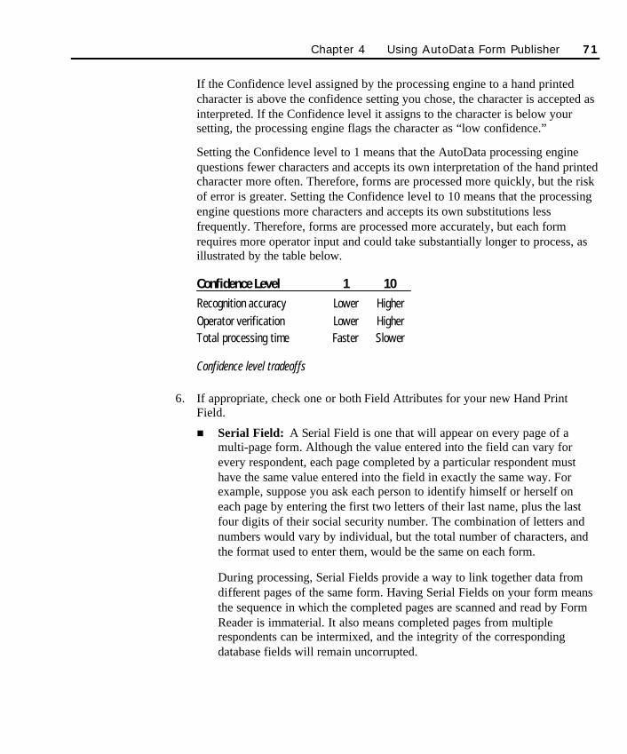
If the Confidence level assigned by the processing engine to a hand printedcharacter is above the confidence setting you chose, the character is accepted asinterpreted. If the Confidence level it assigns to the character is below yoursetting, the processing engine flags the character as “low confidence.”
Setting the Confidence level to 1 means that the AutoData processing enginequestions fewer characters and accepts its own interpretation of the hand printedcharacter more often. Therefore, forms are processed more quickly, but the riskof error is greater. Setting the Confidence level to 10 means that the processingengine questions more characters and accepts its own substitutions lessfrequently. Therefore, forms are processed more accurately, but each formrequires more operator input and could take substantially longer to process, asillustrated by the table below.
Confidence Level 1 10Recognition accuracy Lower HigherOperator verification Lower HigherTotal processing time Faster Slower
Confidence level tradeoffs
6. If appropriate, check one or both Field Attributes for your new Hand PrintField.
n Serial Field: A Serial Field is one that will appear on every page of amulti-page form. Although the value entered into the field can vary forevery respondent, each page completed by a particular respondent musthave the same value entered into the field in exactly the same way. Forexample, suppose you ask each person to identify himself or herself oneach page by entering the first two letters of their last name, plus the lastfour digits of their social security number. The combination of letters andnumbers would vary by individual, but the total number of characters, andthe format used to enter them, would be the same on each form.
During processing, Serial Fields provide a way to link together data fromdifferent pages of the same form. Having Serial Fields on your form meansthe sequence in which the completed pages are scanned and read by FormReader is immaterial. It also means completed pages from multiplerespondents can be intermixed, and the integrity of the correspondingdatabase fields will remain uncorrupted.
Chapter 4 Using AutoData Form Publisher 71
SO Chapter 4 final.qxd 3/21/00 6:22 PM Page 71

IMPORTANT! Proper use of Serial Fields requires that the target database ordata source supports unique index fields. Most spreadsheets (e.g., Microsoft Excel)do NOT support this feature. Most databases and data sources (e.g., MicrosoftAccess) provide unique index field support and will recognize Serial Fields. Makesure your target database supports unique index fields BEFORE placing SerialFields on your form.
Remember, if you plan to use a multi-page form with serialization, and the data willbe stored in one table within a database, make sure ALL of the Serial Fields havethe same field name. By doing so, Form Reader can identify each page andassociate it with one record within the database by a unique identifier.
n Fixed Length: A fixed length field is one where respondents should com-plete every single box in the field with a character. Examples of fixedlength fields include telephone number or social security number HandPrint Fields.
When this option is turned on, empty boxes will be represented by blankspaces in the corresponding database field. Use the fixed length field inconjunction with Verify Field Always or Verify Field if Data Present(explained below) if you want the operator to correct errors or note omis-sions immediately.
7. If appropriate, change the Verify Options settings.
n Verify if Low Confidence: This default setting performs the same func-tion as the Verify Field Always attribute, except that processing only stopsif the software flags a low confidence field.
n Verify Field Always: When this setting is on, processing of the form isalways stopped when this field is reached, so the operator can correct thedata, if necessary.
n Verify Field if Data Present: This setting performs the same function asthe Verify Field Always setting, except that processing only stops if thefield contains any kind of mark in at least one of its boxes.
8. When you are satisfied with your selections in the Hand Print Properties dialogbox, click OK to create your Hand Print Field. An example of a new Hand PrintField is shown in the following figure.
If you selected UserDefined Type in Step 4of these instructions,refer to the nextsection, Creating UserDefined Type HandPrint Fields, foradditional steps tofollow when creatingyour field.
72 Chapter 4 Using AutoData Form Publisher
SO Chapter 4 final.qxd 3/21/00 6:22 PM Page 72
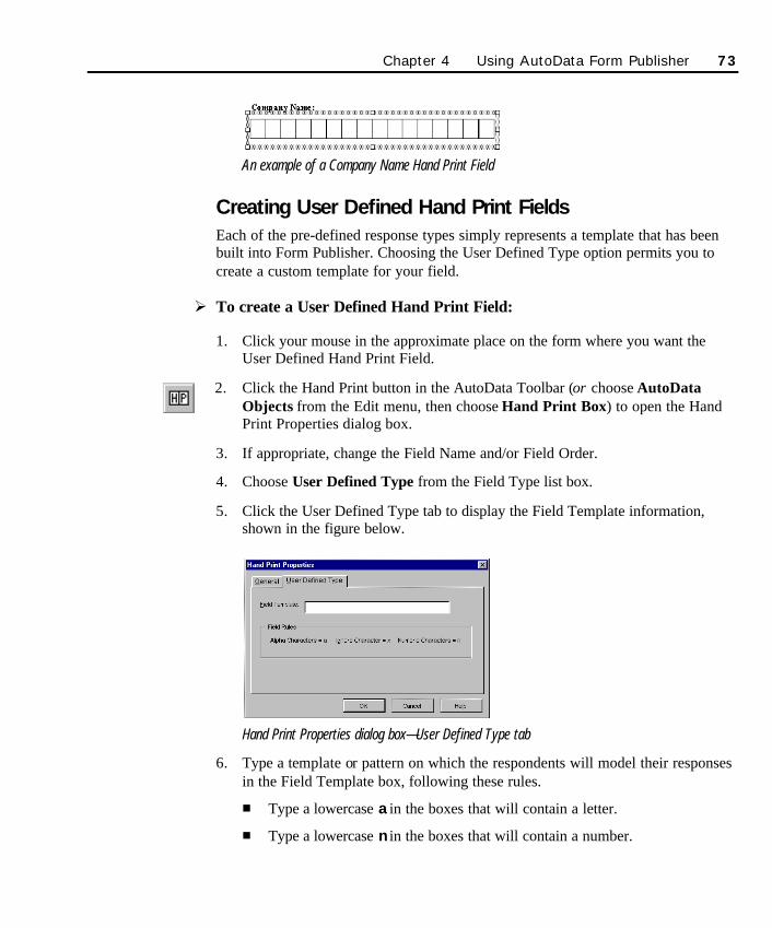
An example of a Company Name Hand Print Field
Creating User Defined Hand Print FieldsEach of the pre-defined response types simply represents a template that has beenbuilt into Form Publisher. Choosing the User Defined Type option permits you tocreate a custom template for your field.
Ø To create a User Defined Hand Print Field:
1. Click your mouse in the approximate place on the form where you want theUser Defined Hand Print Field.
2. Click the Hand Print button in the AutoData Toolbar (or choose AutoDataObjects from the Edit menu, then choose Hand Print Box) to open the HandPrint Properties dialog box.
3. If appropriate, change the Field Name and/or Field Order.
4. Choose User Defined Type from the Field Type list box.
5. Click the User Defined Type tab to display the Field Template information,shown in the figure below.
Hand Print Properties dialog box—User Defined Type tab
6. Type a template or pattern on which the respondents will model their responsesin the Field Template box, following these rules.
n Type a lowercase a in the boxes that will contain a letter.
n Type a lowercase n in the boxes that will contain a number.
Chapter 4 Using AutoData Form Publisher 73
SO Chapter 4 final.qxd 3/21/00 6:22 PM Page 73
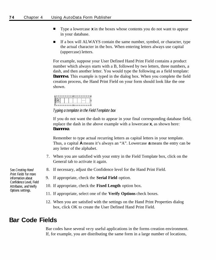
n Type a lowercase x in the boxes whose contents you do not want to appearin your database.
n If a box will ALWAYS contain the same number, symbol, or character, typethe actual character in the box. When entering letters always use capital(uppercase) letters.
For example, suppose your User Defined Hand Print Field contains a productnumber which always starts with a B, followed by two letters, three numbers, adash, and then another letter. You would type the following as a field template:Baannn-a. This example is typed in the dialog box. When you complete the fieldcreation process, the Hand Print Field on your form should look like the oneshown.
Typing a template in the Field Template box
If you do not want the dash to appear in your final corresponding database field,replace the dash in the above example with a lowercase x, as shown here:Baannnxa
Remember to type actual recurring letters as capital letters in your template.Thus, a capital A means it’s always an “A”. Lowercase a means the entry can beany letter of the alphabet.
7. When you are satisfied with your entry in the Field Template box, click on theGeneral tab to activate it again.
8. If necessary, adjust the Confidence level for the Hand Print Field.
9. If appropriate, check the Serial Field option.
10. If appropriate, check the Fixed Length option box.
11. If appropriate, select one of the Verify Options check boxes.
12. When you are satisfied with the settings on the Hand Print Properties dialogbox, click OK to create the User Defined Hand Print Field.
Bar Code FieldsBar codes have several ve ry useful applications in the forms creation environment.If, for example, you are distributing the same form in a large number of locations,
See Creating HandPrint Fields for moreinformation aboutConfidence Level, FieldAttributes, and VerifyOptions settings.
74 Chapter 4 Using AutoData Form Publisher
SO Chapter 4 final.qxd 3/21/00 6:22 PM Page 74
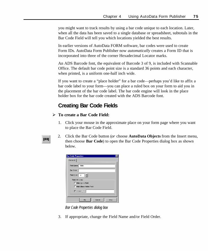
you might want to track results by using a bar code unique to each location. Later,when all the data has been saved to a single database or spreadsheet, subtotals in theBar Code Field will tell you which locations yielded the best results.
In earlier versions of AutoData FORM software, bar codes were used to create Form IDs. AutoData Form Publisher now automatically creates a Form ID that isincorporated into three of the corner Hexadecimal Locator marks.
An ADS Barcode font, the equivalent of Barcode 3 of 9, is included with ScannableOffice. The default bar code point size is a standard 36 points and each character,when printed, is a uniform one-half inch wide.
If you want to create a “place holder” for a bar code—perhaps you’d like to affix abar code label to your form—you can place a ruled box on your form to aid you inthe placement of the bar code label. The bar code engine will look in the placeholder box for the bar code created with the ADS Barcode font.
Creating Bar Code Fields
Ø To create a Bar Code Field:
1. Click your mouse in the approximate place on your form page where you wantto place the Bar Code Field.
2. Click the Bar Code button (or choose AutoData Objects from the Insert menu,then choose Bar Code) to open the Bar Code Properties dialog box as shownbelow.
Bar Code Properties dialog box
3. If appropriate, change the Field Name and/or Field Order.
Chapter 4 Using AutoData Form Publisher 75
SO Chapter 4 final.qxd 3/21/00 6:22 PM Page 75
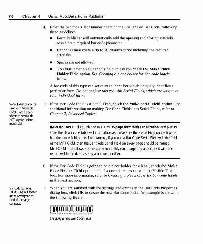
4. Enter the bar code’s alphanumeric text on the line labeled Bar Code, followingthese guidelines:n Form Publisher will automatically add the opening and closing asterisks,
which are a required bar code parameter.
n Bar codes may contain up to 28 characters not including the required asterisks.
n Spaces are not allowed.
n You must enter a value in this field unless you check the Make PlaceHolder Field option. See Creating a place holder for bar code labels,below.
A bar code of this type can serve as an identifier which uniquely identifies aparticular form. Do not confuse this use with Serial Fields, which are unique toeach individual form.
5. If the Bar Code Field is a Serial Field, check the Make Serial Field option. Foradditional information on making Bar Code Fields into Serial Fields, refer toChapter 7, Advanced Topics.
IMPORTANT! If you plan to use a multi-page form with serialization, and plan tostore the data in one table within a database, make sure the Serial Field on each pagehas the same field name. For example, if you use a Bar Code Serial Field with the fieldname MY FORM, then the Bar Code Serial Field on every page should be named MY FORM. This allows Form Reader to identify each page and associate it with onerecord within the database by a unique identifier.
6. If the Bar Code Field is going to be a place holder for a label, check the MakePlace Holder Field option and, if appropriate, enter text in the Visible Textbox. For more information, refer to Creating a placeholder for bar code labelsin the next section.
7. When you are satisfied with the settings and entries in the Bar Code Propertiesdialog box, click OK to create the new Bar Code Field. An example is shown inthe following figure.
Creating a new Bar Code Field
Bar code text (e.g.,LOCATION) will appearin the correspondingfield of the targetdatabase.
Serial Fields cannot beused with MicrosoftExcel, since spread-sheets in general doNOT support uniqueindex fields.
76 Chapter 4 Using AutoData Form Publisher
SO Chapter 4 final.qxd 3/21/00 6:22 PM Page 76
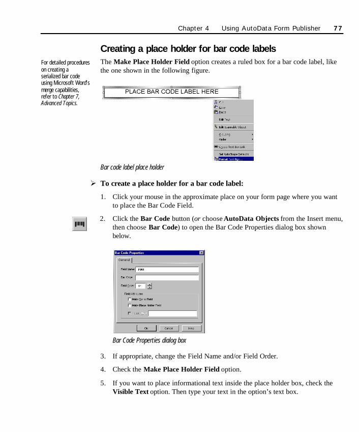
Creating a place holder for bar code labelsThe Make Place Holder Field option creates a ruled box for a bar code label, likethe one shown in the following figure.
Bar code label place holder
Ø To create a place holder for a bar code label:
1. Click your mouse in the approximate place on your form page where you wantto place the Bar Code Field.
2. Click the Bar Code button (or choose AutoData Objects from the Insert menu,then choose Bar Code) to open the Bar Code Properties dialog box shownbelow.
Bar Code Properties dialog box
3. If appropriate, change the Field Name and/or Field Order.
4. Check the Make Place Holder Field option.
5. If you want to place informational text inside the place holder box, check theVisible Text option. Then type your text in the option’s text box.
For detailed procedureson creating aserialized bar codeusing Microsoft Word’smerge capabilities,refer to Chapter 7,Advanced Topics.
Chapter 4 Using AutoData Form Publisher 77
SO Chapter 4 final.qxd 3/21/00 6:22 PM Page 77
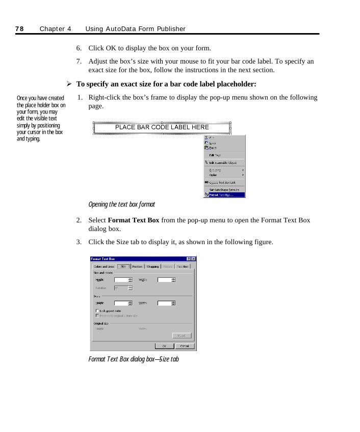
6. Click OK to display the box on your form.
7. Adjust the box’s size with your mouse to fit your bar code label. To specify anexact size for the box, follow the instructions in the next section.
Ø To specify an exact size for a bar code label placeholder:
1. Right-click the box’s frame to display the pop-up menu shown on the followingpage.
Opening the text box format
2. Select Format Text Box from the pop-up menu to open the Format Text Boxdialog box.
3. Click the Size tab to display it, as shown in the following figure.
Format Text Box dialog box—Size tab
Once you have createdthe place holder box onyour form, you mayedit the visible textsimply by positioningyour cursor in the boxand typing.
78 Chapter 4 Using AutoData Form Publisher
SO Chapter 4 final.qxd 3/21/00 6:22 PM Page 78
4. Enter the precise dimensions of your label in the Height and Width fields. Thenclick OK.
Bar Code vs. OCR: You can place a serial number or other information on your formusing a bar code or OCR (Optical Character Recognition) text. Regardless of whether thisplacement is by label or direct merge to the form, you should consider the pros and cons ofeach approach.
If the bar code label is initially affixed to the outside of your packaging and is critical tomanufacturing, warehousing, tracking or shipping functions, then by all means stay with thebar code format. Use of the place holder box option for this field, with instructions for the userof the form to transfer the label to it, is the easiest way to effectively implement this strategy.
The actual merge of data to create individualized bar coded forms is more complex (seeChapter 7, Advanced Topics) but worth the effort. While you will probably find it easier toproduce and process an OCR version of the serial number or other information, be awarethat the bar code is the best choice for accuracy of recognition.
OCR FieldsAn OCR Field may be used to collect alphanumeric text from your form. One of themost common applications is to serialize documents using a preprinted OCR label,or one that has been printed directly on the form using Word’s merge capabilities.The text is read by the OCR engine that is part of AutoData Form Reader.
Creating an OCR FieldØ To create an OCR Field:
1. Click your mouse in the approximate place on your form where you want toplace the OCR Field.
2. Click the OCR button (or choose AutoData Objects from the Insert menu, thenselect OCR) to open the OCR Properties dialog box, shown in the followingfigure.
Chapter 4 Using AutoData Form Publisher 79
SO Chapter 4 final.qxd 3/21/00 6:23 PM Page 79
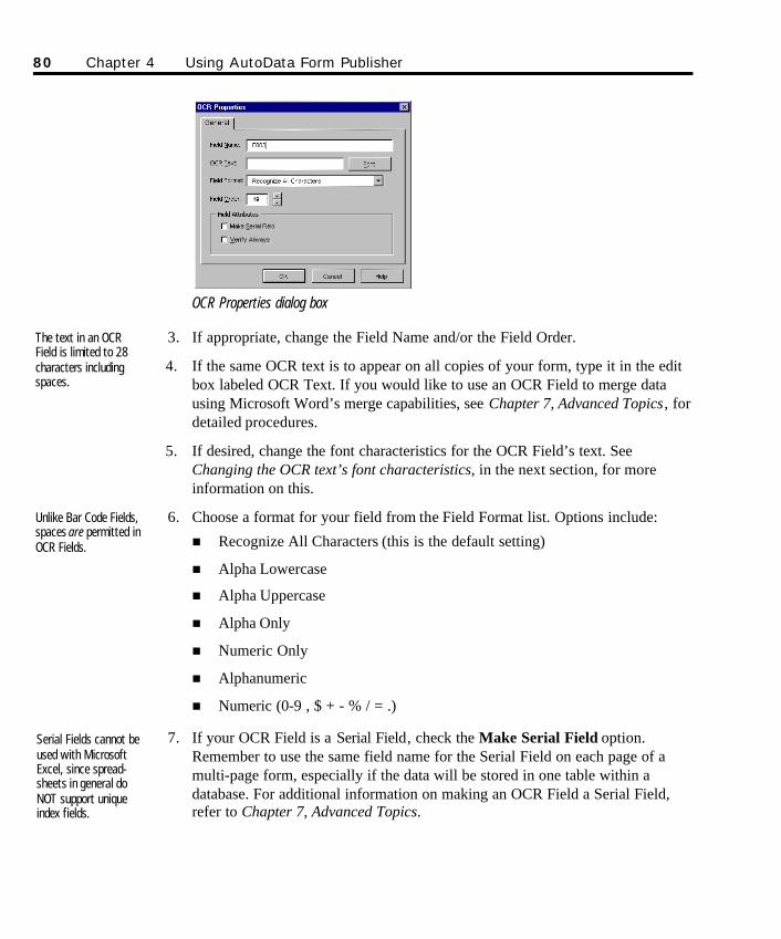
OCR Properties dialog box
3. If appropriate, change the Field Name and/or the Field Order.
4. If the same OCR text is to appear on all copies of your form, type it in the editbox labeled OCR Text. If you would like to use an OCR Field to merge datausing Microsoft Word’s merge capabilities, see Chapter 7, Advanced Topics, fordetailed procedures.
5. If desired, change the font characteristics for the OCR Field’s text. SeeChanging the OCR text’s font characteristics, in the next section, for moreinformation on this.
6. Choose a format for your field from the Field Format list. Options include:
n Recognize All Characters (this is the default setting)
n Alpha Lowercase
n Alpha Uppercase
n Alpha Only
n Numeric Only
n Alphanumeric
n Numeric (0-9 , $ + - % / = .)
7. If your OCR Field is a Serial Field, check the Make Serial Field option.Remember to use the same field name for the Serial Field on each page of amulti-page form, especially if the data will be stored in one table within adatabase. For additional information on making an OCR Field a Serial Field,refer to Chapter 7, Advanced Topics.
Serial Fields cannot beused with MicrosoftExcel, since spread-sheets in general doNOT support uniqueindex fields.
Unlike Bar Code Fields,spaces are permitted inOCR Fields.
The text in an OCRField is limited to 28characters includingspaces.
80 Chapter 4 Using AutoData Form Publisher
SO Chapter 4 final.qxd 3/21/00 6:23 PM Page 80
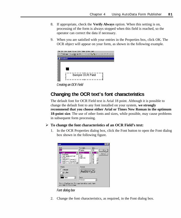
8. If appropriate, check the Verify Always option. When this setting is on,processing of the form is always stopped when this field is reached, so theoperator can correct the data if necessary.
9. When you are satisfied with your entries in the Properties box, click OK. TheOCR object will appear on your form, as shown in the following example.
Creating an OCR Field
Changing the OCR text’s font characteristicsThe default font for OCR Field text is Arial 18 point. Although it is possible tochange the default font to any font installed on your system, we stronglyrecommend that you choose either Arial or Times New Roman in the optimum18-point size. The use of other fonts and sizes, while possible, may cause problemsin subsequent form processing.
Ø To change the font characteristics of an OCR Field’s text:1. In the OCR Properties dialog box, click the Font button to open the Font dialog
box shown in the following figure.
Font dialog box
2. Change the font characteristics, as required, in the Font dialog box.
Chapter 4 Using AutoData Form Publisher 81
SO Chapter 4 final.qxd 3/21/00 6:23 PM Page 81
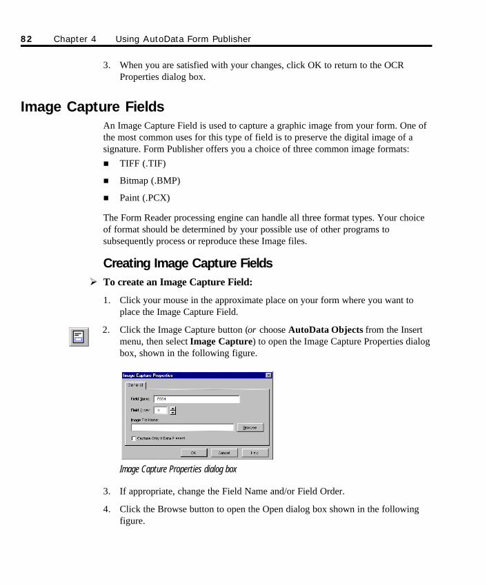
3. When you are satisfied with your changes, click OK to return to the OCRProperties dialog box.
Image Capture FieldsAn Image Capture Field is used to capture a graphic image from your form. One ofthe most common uses for this type of field is to preserve the digital image of asignature. Form Publisher offers you a choice of three common image formats:n TIFF (.TIF)
n Bitmap (.BMP)
n Paint (.PCX)
The Form Reader processing engine can handle all three format types. Your choiceof format should be determined by your possible use of other programs tosubsequently process or reproduce these Image files.
Creating Image Capture FieldsØ To create an Image Capture Field:
1. Click your mouse in the approximate place on your form where you want toplace the Image Capture Field.
2. Click the Image Capture button (or choose AutoData Objects from the Insertmenu, then select Image Capture) to open the Image Capture Properties dialogbox, shown in the following figure.
Image Capture Properties dialog box
3. If appropriate, change the Field Name and/or Field Order.
4. Click the Browse button to open the Open dialog box shown in the followingfigure.
82 Chapter 4 Using AutoData Form Publisher
SO Chapter 4 final.qxd 3/21/00 6:23 PM Page 82
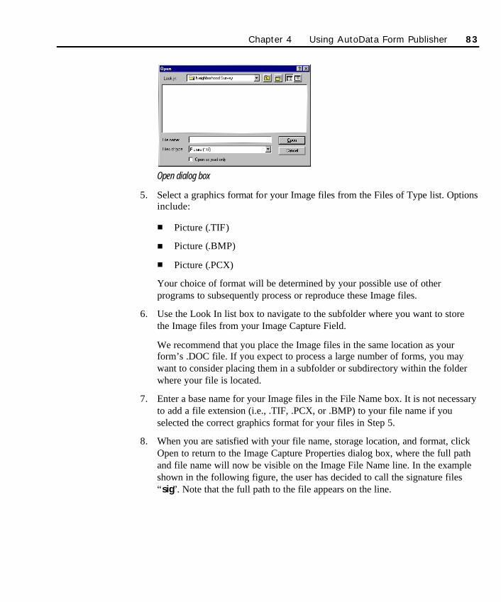
Open dialog box
5. Select a graphics format for your Image files from the Files of Type list. Optionsinclude:
n Picture (.TIF)
n Picture (.BMP)
n Picture (.PCX)
Your choice of format will be determined by your possible use of otherprograms to subsequently process or reproduce these Image files.
6. Use the Look In list box to navigate to the subfolder where you want to storethe Image files from your Image Capture Field.
We recommend that you place the Image files in the same location as yourform’s .DOC file. If you expect to process a large number of forms, you maywant to consider placing them in a subfolder or subdirectory within the folderwhere your file is located.
7. Enter a base name for your Image files in the File Name box. It is not necessaryto add a file extension (i.e., .TIF, .PCX, or .BMP) to your file name if youselected the correct graphics format for your files in Step 5.
8. When you are satisfied with your file name, storage location, and format, clickOpen to return to the Image Capture Properties dialog box, where the full pathand file name will now be visible on the Image File Name line. In the exampleshown in the following figure, the user has decided to call the signature files“sig”. Note that the full path to the file appears on the line.
Chapter 4 Using AutoData Form Publisher 83
SO Chapter 4 final.qxd 3/21/00 6:23 PM Page 83
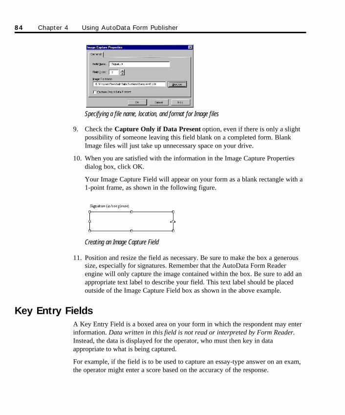
Specifying a file name, location, and format for Image files
9. Check the Capture Only if Data Present option, even if there is only a slightpossibility of someone leaving this field blank on a completed form. BlankImage files will just take up unnecessary space on your drive.
10. When you are satisfied with the information in the Image Capture Propertiesdialog box, click OK.
Your Image Capture Field will appear on your form as a blank rectangle with a1-point frame, as shown in the following figure.
Creating an Image Capture Field
11. Position and resize the field as necessary. Be sure to make the box a generoussize, especially for signatures. Remember that the AutoData Form Readerengine will only capture the image contained within the box. Be sure to add anappropriate text label to describe your field. This text label should be placedoutside of the Image Capture Field box as shown in the above example.
Key Entry FieldsA Key Entry Field is a boxed area on your form in which the respondent may enterinformation. Data written in this field is not read or interpreted by Form Reader.Instead, the data is displayed for the operator, who must then key in dataappropriate to what is being captured.
For example, if the field is to be used to capture an essay-type answer on an exam,the operator might enter a score based on the accuracy of the response.
84 Chapter 4 Using AutoData Form Publisher
SO Chapter 4 final.qxd 3/21/00 6:23 PM Page 84
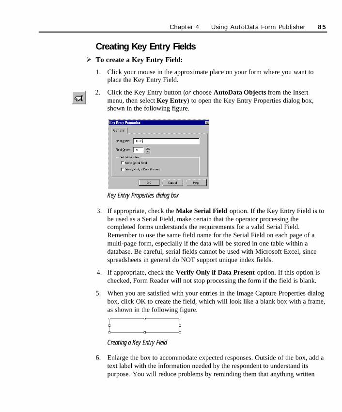
Creating Key Entry FieldsØ To create a Key Entry Field:
1. Click your mouse in the approximate place on your form where you want toplace the Key Entry Field.
2. Click the Key Entry button (or choose AutoData Objects from the Insertmenu, then select Key Entry) to open the Key Entry Properties dialog box,shown in the following figure.
Key Entry Properties dialog box
3. If appropriate, check the Make Serial Field option. If the Key Entry Field is tobe used as a Serial Field, make certain that the operator processing thecompleted forms understands the requirements for a valid Serial Field.Remember to use the same field name for the Serial Field on each page of amulti-page form, especially if the data will be stored in one table within adatabase. Be careful, serial fields cannot be used with Microsoft Excel, sincespreadsheets in general do NOT support unique index fields.
4. If appropriate, check the Verify Only if Data Present option. If this option ischecked, Form Reader will not stop processing the form if the field is blank.
5. When you are satisfied with your entries in the Image Capture Properties dialogbox, click OK to create the field, which will look like a blank box with a frame,as shown in the following figure.
Creating a Key Entry Field
6. Enlarge the box to accommodate expected responses. Outside of the box, add atext label with the information needed by the respondent to understand itspurpose. You will reduce problems by reminding them that anything written
Chapter 4 Using AutoData Form Publisher 85
SO Chapter 4 final.qxd 3/21/00 6:23 PM Page 85
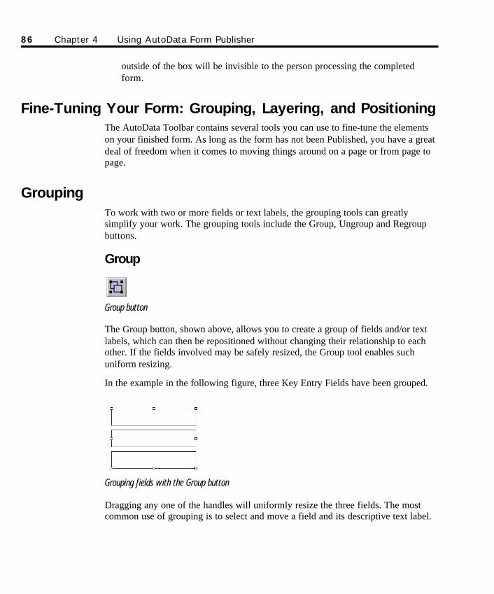
outside of the box will be invisible to the person processing the completedform.
Fine-Tuning Your Form: Grouping, Layering, and Positioning The AutoData Toolbar contains several tools you can use to fine-tune the elementson your finished form. As long as the form has not been Published, you have a greatdeal of freedom when it comes to moving things around on a page or from page topage.
GroupingTo work with two or more fields or text labels, the grouping tools can greatlysimplify your work. The grouping tools include the Group, Ungroup and Regroupbuttons.
Group
Group button
The Group button, shown above, allows you to create a group of fields and/or textlabels, which can then be repositioned without changing their relationship to eachother. If the fields involved may be safely resized, the Group tool enables suchuniform resizing.
In the example in the following figure, three Key Entry Fields have been grouped.
Grouping fields with the Group button
Dragging any one of the handles will uniformly resize the three fields. The mostcommon use of grouping is to select and move a field and its descriptive text label.
86 Chapter 4 Using AutoData Form Publisher
SO Chapter 4 final.qxd 3/21/00 6:23 PM Page 86

Ø To group two or more elements on your page:
1. Click on one of the elements you want to group.
2. Hold down the Shift key and click the second element you want to add to thegroup.
3. Repeat Step 2 as many times as needed (select no more than 5 layers ofelements) until all the elements you want grouped together are selected.
IMPORTANT! Do not group more than 5 layers of groups inside groups. Form Publisherwill only ungroup 5 levels deep when Publishing the form.
4. Click the Group button on the AutoData Toolbar to group the elements.
Ungroup
Ungroup button
The Ungroup button is used to ungroup elements in a group.
Ø To ungroup a group of elements:
1. Select the grouped elements you want to ungroup.
2. Click the Ungroup button.
The grouped elements will be ungrouped, although they will still be selected.Click anywhere on your form to deselect the elements.
Regroup
Regroup button
The Regroup button regroups the last ungrouped group. If you reposition a groupand then ungroup the elements, and then decide they’re not quite where you wantthem, click the Regroup tool to reconstitute the last grouping.
Chapter 4 Using AutoData Form Publisher 87
SO Chapter 4 final.qxd 3/21/00 6:23 PM Page 87
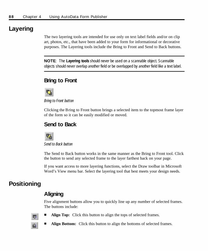
LayeringThe two layering tools are intended for use only on text label fields and/or on clipart, photos, etc., that have been added to your form for informational or decorativepurposes. The Layering tools include the Bring to Front and Send to Back buttons.
NOTE: The Layering tools should never be used on a scannable object. Scannableobjects should never overlap another field or be overlapped by another field like a text label.
Bring to Front
Bring to Front button
Clicking the Bring to Front button brings a selected item to the topmost frame layerof the form so it can be easily modified or moved.
Send to Back
Send to Back button
The Send to Back button works in the same manner as the Bring to Front tool. Clickthe button to send any selected frame to the layer farthest back on your page.
If you want access to more layering functions, select the Draw toolbar in MicrosoftWord’s View menu bar. Select the layering tool that best meets your design needs.
Positioning
AligningFive alignment buttons allow you to quickly line up any number of selected frames.The buttons include:
n Align Top: Click this button to align the tops of selected frames.
n Align Bottom: Click this button to align the bottoms of selected frames.
88 Chapter 4 Using AutoData Form Publisher
SO Chapter 4 final.qxd 3/21/00 6:23 PM Page 88
n Align Center: Click this button to align the centers of selected frames.
n Align Left: Click this button to align the left sides of selected frames.
n Align Right: Click this button to align the right sides of selected frames.
Ø To use one of the alignment buttons:
1. Click on one of the elements you want to align.
2. Hold down the Shift key and click the second element you want to align withthe first element.
3. Repeat Step 2 as many times as needed until all the elements you want alignedare selected.
4. Click the appropriate alignment button.
If necessary, restore the elements to their original position by choosing UndoAlign Object from the Edit menu.
SpacingThe two Spacing buttons automate the vertical or horizontal spacing of selectedframes:
n Distribute Horizontally: This button, which becomes operational when threeor more elements are selected, is used to equally space the selected elementshorizontally.
n Distribute Vertically: This button, which becomes operational when three ormore elements are selected, is used to equally space the selected elementsvertically.
Note that the vertical or horizontal spacing of the selected elements is relative to theselected frames, and not to the vertical or horizontal dimensions of the page.
Ø To use the spacing buttons:
1. Position the top and bottom elements—or the furthest left and right elements—in their final location.
2. Select (Shift+click) all of the elements to be spaced evenly, including the just-positioned top/bottom or left/right elements.
3. When all the elements are selected, click either the Distribute Horizontally orthe Distribute Vertically button.
Chapter 4 Using AutoData Form Publisher 89
SO Chapter 4 final.qxd 3/21/00 6:23 PM Page 89
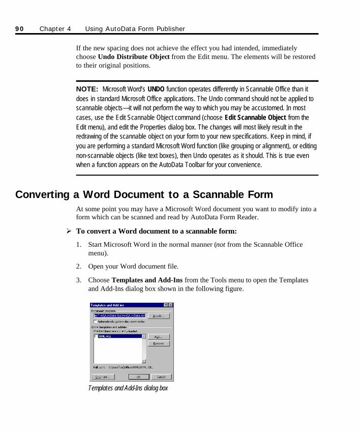
If the new spacing does not achieve the effect you had intended, immediatelychoose Undo Distribute Object from the Edit menu. The elements will be restoredto their original positions.
NOTE: Microsoft Word’s UNDO function operates differently in Scannable Office than itdoes in standard Microsoft Office applications. The Undo command should not be applied toscannable objects—it will not perform the way to which you may be accustomed. In mostcases, use the Edit Scannable Object command (choose Edit Scannable Object from theEdit menu), and edit the Properties dialog box. The changes will most likely result in theredrawing of the scannable object on your form to your new specifications. Keep in mind, ifyou are performing a standard Microsoft Word function (like grouping or alignment), or editingnon-scannable objects (like text boxes), then Undo operates as it should. This is true evenwhen a function appears on the AutoData Toolbar for your convenience.
Converting a Word Document to a Scannable Form At some point you may have a Microsoft Word document you want to modify into aform which can be scanned and read by AutoData Form Reader.
Ø To convert a Word document to a scannable form:
1. Start Microsoft Word in the normal manner (not from the Scannable Officemenu).
2. Open your Word document file.
3. Choose Templates and Add-Ins from the Tools menu to open the Templatesand Add-Ins dialog box shown in the following figure.
Templates and Add-Ins dialog box
90 Chapter 4 Using AutoData Form Publisher
SO Chapter 4 final.qxd 3/21/00 6:23 PM Page 90
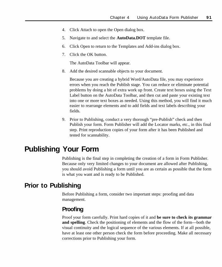
4. Click Attach to open the Open dialog box.
5. Navigate to and select the AutoData.DOT template file.
6. Click Open to return to the Templates and Add-ins dialog box.
7. Click the OK button.
The AutoData Toolbar will appear.
8. Add the desired scannable objects to your document.
Because you are creating a hybrid Word/AutoData file, you may experienceerrors when you reach the Publish stage. You can reduce or eliminate potentialproblems by doing a bit of extra work up front. Create text boxes using the TextLabel button on the AutoData Toolbar, and then cut and paste your existing textinto one or more text boxes as needed. Using this method, you will find it mucheasier to rearrange elements and to add fields and text labels describing yourfields.
9. Prior to Publishing, conduct a very thorough “pre-Publish” check and thenPublish your form. Form Publisher will add the Locator marks, etc., in this finalstep. Print reproduction copies of your form after it has been Published andtested for scannability.
Publishing Your FormPublishing is the final step in completing the creation of a form in Form Publisher.Because only very limited changes to your document are allowed after Publishing,you should avoid Publishing a form until you are as certain as possible that the formis what you want and is ready to be Published.
Prior to PublishingBefore Publishing a form, consider two important steps: proofing and datamanagement.
ProofingProof your form carefully. Print hard copies of it and be sure to check its grammarand spelling. Check the positioning of elements and the flow of the form—both thevisual continuity and the logical sequence of the various elements. If at all possible,have at least one other person check the form before proceeding. Make all necessarycorrections prior to Publishing your form.
Chapter 4 Using AutoData Form Publisher 91
SO Chapter 4 final.qxd 3/21/00 6:23 PM Page 91
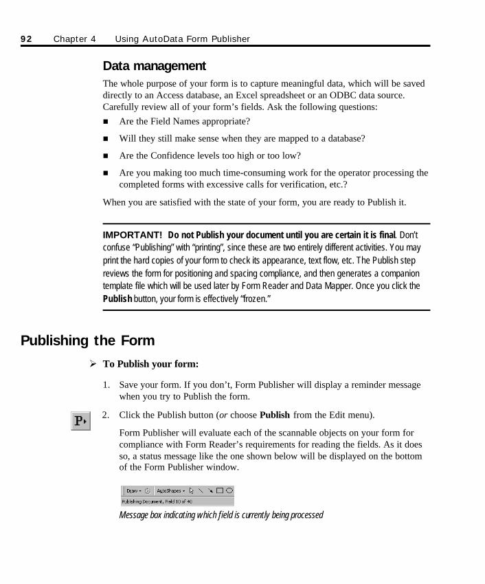
Data managementThe whole purpose of your form is to capture meaningful data, which will be saveddirectly to an Access database, an Excel spreadsheet or an ODBC data source.Carefully review all of your form’s fields. Ask the following questions:n Are the Field Names appropriate?
n Will they still make sense when they are mapped to a database?
n Are the Confidence levels too high or too low?
n Are you making too much time-consuming work for the operator processing thecompleted forms with excessive calls for verification, etc.?
When you are satisfied with the state of your form, you are ready to Publish it.
IMPORTANT! Do not Publish your document until you are certain it is final. Don’tconfuse “Publishing” with “printing”, since these are two entirely different activities. You mayprint the hard copies of your form to check its appearance, text flow, etc. The Publish stepreviews the form for positioning and spacing compliance, and then generates a companiontemplate file which will be used later by Form Reader and Data Mapper. Once you click thePublish button, your form is effectively “frozen.”
Publishing the FormØ To Publish your form:
1. Save your form. If you don’t, Form Publisher will display a reminder messagewhen you try to Publish the form.
2. Click the Publish button (or choose Publish from the Edit menu).
Form Publisher will evaluate each of the scannable objects on your form forcompliance with Form Reader’s requirements for reading the fields. As it doesso, a status message like the one shown below will be displayed on the bottomof the Form Publisher window.
Message box indicating which field is currently being processed
92 Chapter 4 Using AutoData Form Publisher
SO Chapter 4 final.qxd 3/21/00 6:23 PM Page 92
Three variables—page length, page complexity and computer processingspeed—all impact a form’s Publish time. A short form with few scannableobjects will Publish much faster than a long form containing many scannableobjects. Publish time is even more dramatically impacted by the computer’sprocessor speed. Patience may be required during the Publish routine when aform is complex.
NOTE: During the Publish routine, expect to see a great deal of activity on yourcomputer monitor screen. Your form will appear to jump around. Scannable objectframes will become momentarily highlighted as Form Publisher reviews each scannableobject. A status bar message will keep you informed on progress with a constantlyupdated message that indicates which field on your form is being processed.
The Publish routine’s internal process involves a very thorough review of aspecific checklist of parameters. This step is generally completely invisible toyou unless the check encounters an error that warrants correction. If that shouldoccur, an appropriate error message is displayed. When you click OK toacknowledge the error message, the object that has violated the rules will beselected. You can correct the problem and Publish again. Once all positionalrule violations have been corrected, the Publish routine will create a Form(.FRM) file.
Among other things, the Publish routine checks the following:
n There are no more than 25 pages.
n Each page has correct Locator marks.
n All fields are positioned correctly for scanning.
n Serial Field (if used) is validated for correctness.
n Field rules appropriate for each type of field are checked.
The Publish routine creates a Form (.FRM) file. This file, which is placed in thesame location as your Word .DOC file, contains all the important informationneeded by the Data Mapper and Form Reader modules for subsequent handlingof your form.
When the Publish routine is completed successfully, the message box shown inthe following figure will be displayed.
Serial Fields cannot beused with MicrosoftExcel, since spread-sheets in general doNOT support uniqueindex fields.
Always print a hardcopy of your form afterit has been Published,because the Publishroutine may modifyfield positions. Verifythe final form to makesure there are nosurprises in the output.
Chapter 4 Using AutoData Form Publisher 93
SO Chapter 4 final.qxd 3/21/00 6:23 PM Page 93
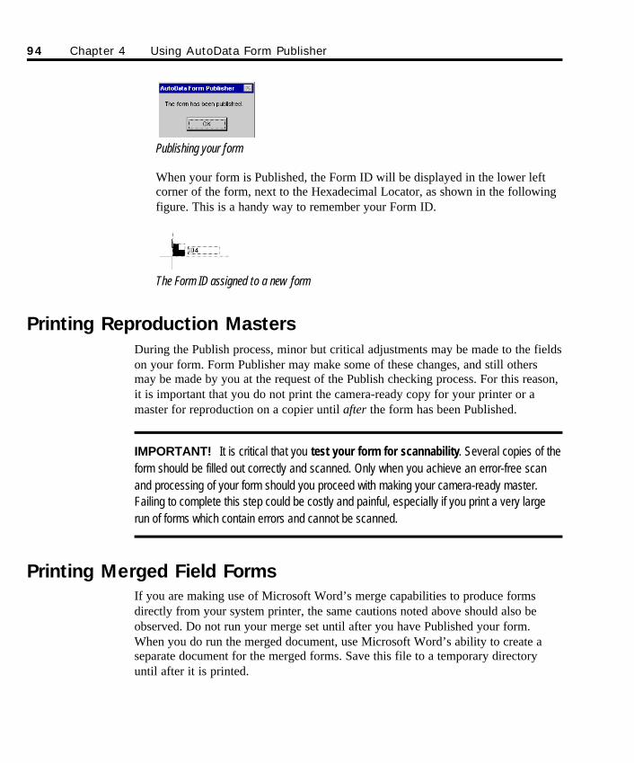
Publishing your form
When your form is Published, the Form ID will be displayed in the lower leftcorner of the form, next to the Hexadecimal Locator, as shown in the followingfigure. This is a handy way to remember your Form ID.
The Form ID assigned to a new form
Printing Reproduction MastersDuring the Publish process, minor but critical adjustments may be made to the fieldson your form. Form Publisher may make some of these changes, and still othersmay be made by you at the request of the Publish checking process. For this reason,it is important that you do not print the camera-ready copy for your printer or amaster for reproduction on a copier until after the form has been Published.
IMPORTANT! It is critical that you test your form for scannability. Several copies of theform should be filled out correctly and scanned. Only when you achieve an error-free scanand processing of your form should you proceed with making your camera-ready master.Failing to complete this step could be costly and painful, especially if you print a very largerun of forms which contain errors and cannot be scanned.
Printing Merged Field FormsIf you are making use of Microsoft Word’s merge capabilities to produce formsdirectly from your system printer, the same cautions noted above should also beobserved. Do not run your merge set until after you have Published your form.When you do run the merged document, use Microsoft Word’s ability to create aseparate document for the merged forms. Save this file to a temporary directoryuntil after it is printed.
94 Chapter 4 Using AutoData Form Publisher
SO Chapter 4 final.qxd 3/21/00 6:23 PM Page 94

The merge document can be quite large. If, for example, you have a 10-page formand are running 500 copies, the merge document will be 5,000 pages. Make sureyou have enough disk drive space for this document as well as for the large spoolfile which will be produced when you actually begin printing your forms.Remember to delete the large merged field document when you finish printing. Ifyou have saved it to a temporary directory, it will be easier to locate and delete.More importantly, there will be less chance of accidentally deleting critical filesneeded for subsequent processing of your forms.
AutoData Form Reader (as well as Data Mapper) will use your original master form.DOC file and the .FRM file created during the Publish process to create thenecessary .MAP file and process your completed forms. The various files created byScannable Office and how they relate to each other are explained in greater detail inAppendix D: AutoData Scannable Office Files.
For more instructionson printing merged fieldforms, see Chapter 7,Advanced Topics.
Chapter 4 Using AutoData Form Publisher 95
SO Chapter 4 final.qxd 3/21/00 6:23 PM Page 95

96 Chapter 4 Using AutoData Form Publisher
SO Chapter 4 final.qxd 3/21/00 6:23 PM Page 96
97
Chapter 5Using AutoData Form Reader
AutoData Form Reader is a sophisticated standalone program capable of processingthe following forms:
n Forms created using AutoData Form Publisher
n Forms defined by AutoData Template Maker
n Forms defined using AutoData FORM 4.0 and higher
When forms are processed, the collected data is immediately stored in a MicrosoftAccess database, a Microsoft Excel spreadsheet, or an ODBC data source. Thiseliminates the extra exporting steps often required by other traditional methods. Ifthere is no existing database, Form Reader can create one in either Access (2000 or97 compatible versions) or Excel format with the help of an easy-to-use Wizard.The database may be opened and edited from within Form Reader for yourconvenience.
Form Reader processes forms from a variety of input sources:
n Imaging scanners are the most common input source. Form Reader supports thetwo most popular scanner interfaces, ISIS and TWAIN.
n Single-page TIFF files created by other programs are supported by FormReader through an Import Images feature. After the images are imported, theyare processed and verified in the same manner used for scanned forms.
n PaperPort scans forms and saves them as Image files. The files are importedinto Form Reader and recorded in the Image database prior to processing.
See Chapter 7,Advanced Topics formore details on theseprocessingprocedures.
SO Chapter 5 Final.qxd 3/21/00 6:26 PM Page 97
98 Chapter 5 Using AutoData Form Reader
n WinFax PRO accepts forms received as facsimile transmissions by single-userinstallations. These forms are then imported into Form Reader as TIFF Imagefiles, ready to be processed.
Form Reader can accept any size form that your input source can handle, up to11"×17" in portrait or landscape mode. With its unique 90-degree rotationcapability, it can even handle some sizes that your input source itself normally couldnot.
Forms may be processed in an interactive mode (that is, scanned and then read andverified sequentially), or they may be simply scanned as a batch and then processedand verified as a batch, either immediately or at a later time. In a networkenvironment, multiple workstations may process forms simultaneously and storedata in a single database, but each station must have an AutoData Protection Keyinstalled on its parallel port.
More than one type of form may be processed in a single session. In fact, dozens ofdifferent types of forms can be processed in any order—with the exception of multi-page forms that should be read in page sequence. In addition, all forms in a batch orinteractive process group must have the same page orientation. All must be inportrait orientation or all must be in landscape orientation. Form Reader will readand route the data from each form to the appropriate database. This capability ispossible as long as each form has a proper Form ID and is “registered” withScannable Office.
In addition to being saved to Access, Excel or ODBC data sources, data can also bedirectly exported from Form Reader in a variety of delimited text formats, thusmaking your data readily available to a wide variety of other programs.
Chapter 5, Using Form Reader, has four parts. The first part, Launching FormReader, describes how to launch the Form Reader software. The second part, TheForm Reader Window, describes the Form Reader toolbar and menu commands. Thethird part, Processing Forms, describes the four steps you will follow to scan andprocess your forms. It also discusses the verification of the data read from a scannedform. The fourth part, Using the Image Viewer, describes how to use the ImageViewer feature of Form Reader, as well as its toolbars and menu commands.
Launching Form ReaderAfter you’ve created your form using Form Publisher or defined an existing ordesktop-published form in Template Maker, and the form has been completed by arespondent, you’re ready to begin the processing phase. Form Reader’s primarypurpose is to scan and process forms.
SO Chapter 5 Final.qxd 3/21/00 6:26 PM Page 98
Ø To launch Form Reader from the desktop or the Start menu:
n During installation, Scannable Office places four shortcut icons on yourdesktop. To start Form Reader, double-click on the desktop icon shown below(or click Start, point to Programs, then point to the AutoData ScannableOffice group, then choose Form Reader)
Form Reader shortcut icon
The Form Reader window, shown in the following figure, will open.
The Form Reader window
The Form Reader Window
The Form Reader ToolbarThe Form Reader Toolbar offers one-click access to most of Form Reader’sfunctions.
n Open Access Database: Opens an Access database.
n Open Excel spreadsheet: Opens an Excel spreadsheet.
n Open ODBC Data Source: Opens the Windows ODBC dialog box foraccessing an ODBC data source.
There is no need toopen the targetdatabase, or even tellForm Reader whichform you areprocessing, becausethese steps areautomated. If FormReader has troubleidentifying your form ordetermining what to dowith the scanned data,it will stop and ask foryour input.
Chapter 5 Using AutoData Form Reader 99
SO Chapter 5 Final.qxd 3/21/00 6:26 PM Page 99
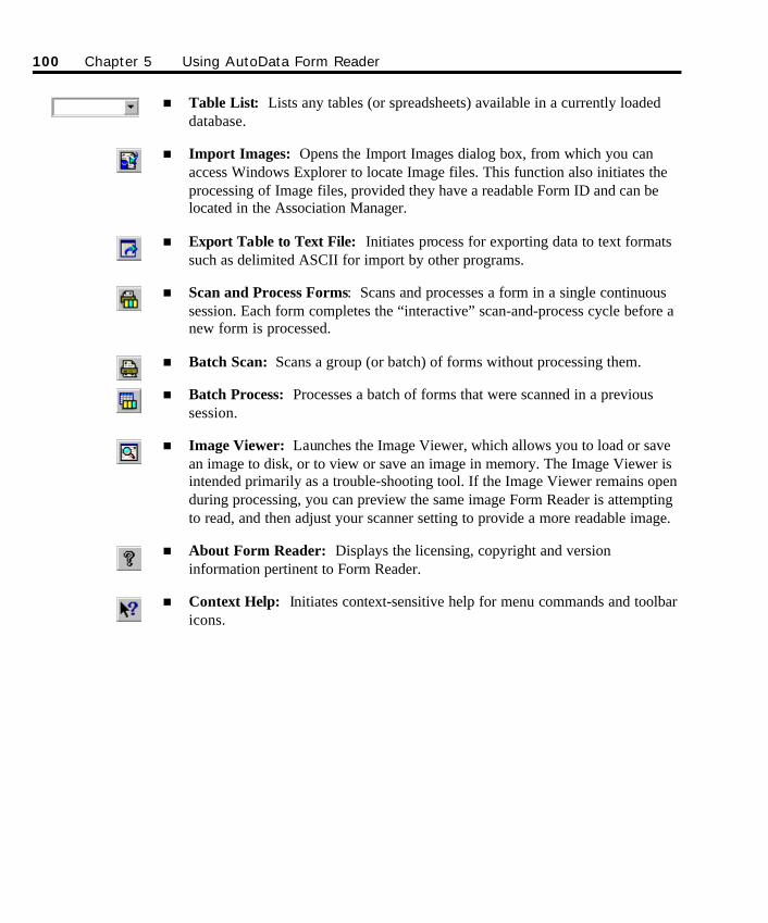
n Table List: Lists any tables (or spreadsheets) available in a currently loadeddatabase.
n Import Images: Opens the Import Images dialog box, from which you canaccess Windows Explorer to locate Image files. This function also initiates theprocessing of Image files, provided they have a readable Form ID and can belocated in the Association Manager.
n Export Table to Text File: Initiates process for exporting data to text formatssuch as delimited ASCII for import by other programs.
n Scan and Process Forms: Scans and processes a form in a single continuoussession. Each form completes the “interactive” scan-and-process cycle before anew form is processed.
n Batch Scan: Scans a group (or batch) of forms without processing them.
n Batch Process: Processes a batch of forms that were scanned in a previoussession.
n Image Viewer: Launches the Image Viewer, which allows you to load or savean image to disk, or to view or save an image in memory. The Image Viewer isintended primarily as a trouble-shooting tool. If the Image Viewer remains openduring processing, you can preview the same image Form Reader is attemptingto read, and then adjust your scanner setting to provide a more readable image.
n About Form Reader: Displays the licensing, copyright and versioninformation pertinent to Form Reader.
n Context Help: Initiates context-sensitive help for menu commands and toolbaricons.
100 Chapter 5 Using AutoData Form Reader
SO Chapter 5 Final.qxd 3/21/00 6:26 PM Page 100
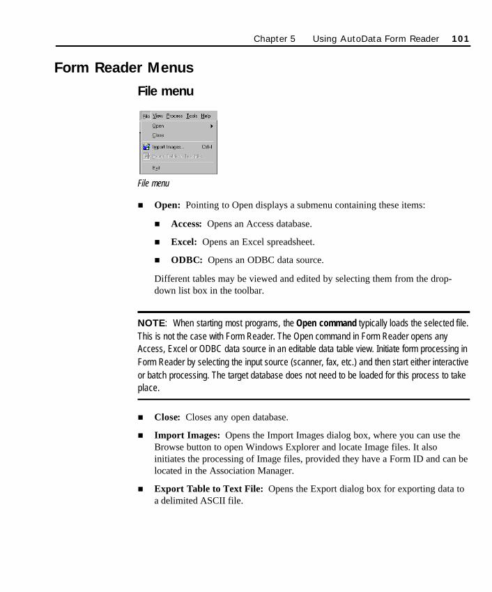
Form Reader Menus
File menu
File menu
n Open: Pointing to Open displays a submenu containing these items:
n Access: Opens an Access database.
n Excel: Opens an Excel spreadsheet.
n ODBC: Opens an ODBC data source.
Different tables may be viewed and edited by selecting them from the drop-down list box in the toolbar.
NOTE: When starting most programs, the Open command typically loads the selected file.This is not the case with Form Reader. The Open command in Form Reader opens anyAccess, Excel or ODBC data source in an editable data table view. Initiate form processing inForm Reader by selecting the input source (scanner, fax, etc.) and then start either interactiveor batch processing. The target database does not need to be loaded for this process to takeplace.
n Close: Closes any open database.
n Import Images: Opens the Import Images dialog box, where you can use theBrowse button to open Windows Explorer and locate Image files. It alsoinitiates the processing of Image files, provided they have a Form ID and can belocated in the Association Manager.
n Export Table to Text File: Opens the Export dialog box for exporting data toa delimited ASCII file.
Chapter 5 Using AutoData Form Reader 101
SO Chapter 5 Final.qxd 3/21/00 6:26 PM Page 101
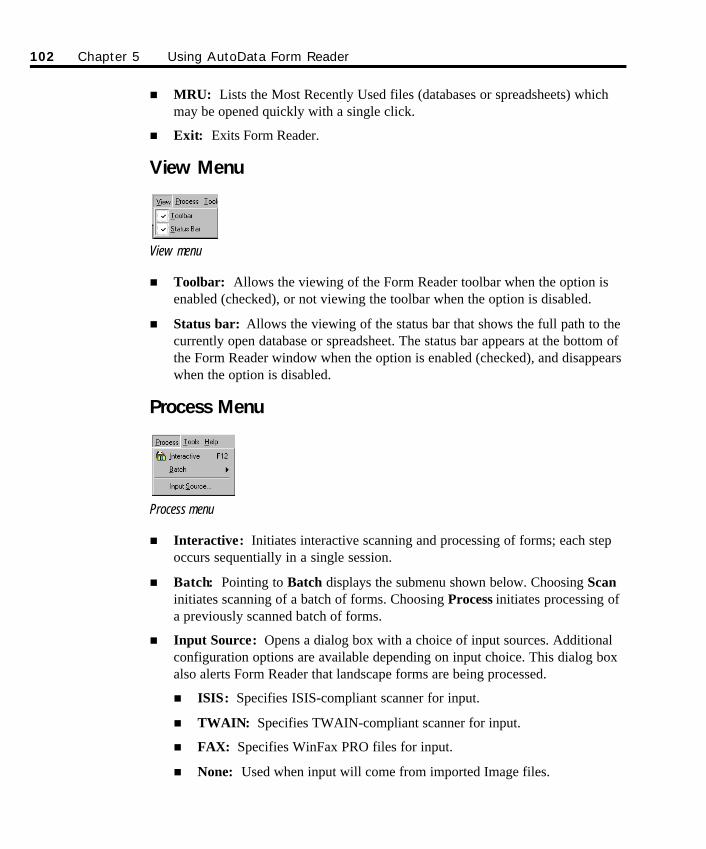
102 Chapter 5 Using AutoData Form Reader
n MRU: Lists the Most Recently Used files (databases or spreadsheets) whichmay be opened quickly with a single click.
n Exit: Exits Form Reader.
View Menu
View menu
n Toolbar: Allows the viewing of the Form Reader toolbar when the option isenabled (checked), or not viewing the toolbar when the option is disabled.
n Status bar: Allows the viewing of the status bar that shows the full path to thecurrently open database or spreadsheet. The status bar appears at the bottom ofthe Form Reader window when the option is enabled (checked), and disappearswhen the option is disabled.
Process Menu
Process menu
n Interactive: Initiates interactive scanning and processing of forms; each stepoccurs sequentially in a single session.
n Batch: Pointing to Batch displays the submenu shown below. Choosing Scaninitiates scanning of a batch of forms. Choosing Process initiates processing ofa previously scanned batch of forms.
n Input Source: Opens a dialog box with a choice of input sources. Additionalconfiguration options are available depending on input choice. This dialog boxalso alerts Form Reader that landscape forms are being processed.
n ISIS: Specifies ISIS-compliant scanner for input.
n TWAIN: Specifies TWAIN-compliant scanner for input.
n FAX: Specifies WinFax PRO files for input.
n None: Used when input will come from imported Image files.
SO Chapter 5 Final.qxd 3/21/00 6:26 PM Page 102
Tools Menu
Tools menu
n Image Viewer: Launches the Form Reader Image Viewer, which allows animage to be loaded or saved to disk or in memory. The Image Viewer isintended primarily as a trouble-shooting tool. If the Image Viewer remains openduring processing, you can preview the image exactly as Form Reader isattempting to read it. This enables you to adjust your scanner setting to providea more readable image.
n Mapper: Launches the AutoData Data Mapper module directly from FormReader for convenient and immediate access to the database mapping utility.
n Options: Opens the Options dialog box, where you can access the internalprogram settings for processing, verification, and training.
Help Menu
Help menu
n Contents and Index: Accesses the Help file Contents and Index.
n Context Help: Launches context-sensitive help and changes the cursor to anarrow with a question mark.
n About Form Reader: Displays copyright and version information specific toyour installation.
Chapter 5 Using AutoData Form Reader 103
SO Chapter 5 Final.qxd 3/21/00 6:26 PM Page 103
Processing Forms
OverviewThis section discusses the details of the sequential steps you need to take to use theForm Reader module to process your forms. Here’s a quick overview of the stepspresented:
n Step 1: Specifying an input source. In this step, you will specify an inputsource—a scanner, fax, or other device—so Form Reader knows where to lookfor incoming forms.
n Step 2: Setting program options. In this step, you will decide on the settingsfor the program options, which will define the rules used in processing. Typicalusers will accept the default settings in most cases.
n Step 3: Scanning your forms. In this step you will use a scanner to scan yourforms using the Interactive processing method.
As you begin scanning forms, Form Reader software performs behind-the-scenes checking to determine:
n The name of the scannable form
n If the scannable form template is registered with Scannable Office
n The final database type and location (Access, Excel, ODBC)
n Where in the final database to store the scanned data (through a Map file)
If any of these elements are missing, Wizards will offer assistance. These areone-time steps that take just a minute to complete. If you are scanning anexisting form, these checkpoints have most likely been performed up front, soscanning proceeds without interruption.
n Step 4: Processing and verifying your scanned data. In this step, you willprocess and verify the scanned data as needed. The actions taken will depend onthe options and verification criteria you selected up front, and the content ofyour form. Form Reader has different processes for verifying differentscannable object types, and operator input varies accordingly.
When this step is complete, the scanned data will have been placed directly inyour database of choice, with no cumbersome export steps.
104 Chapter 5 Using AutoData Form Reader
SO Chapter 5 Final.qxd 3/21/00 6:26 PM Page 104
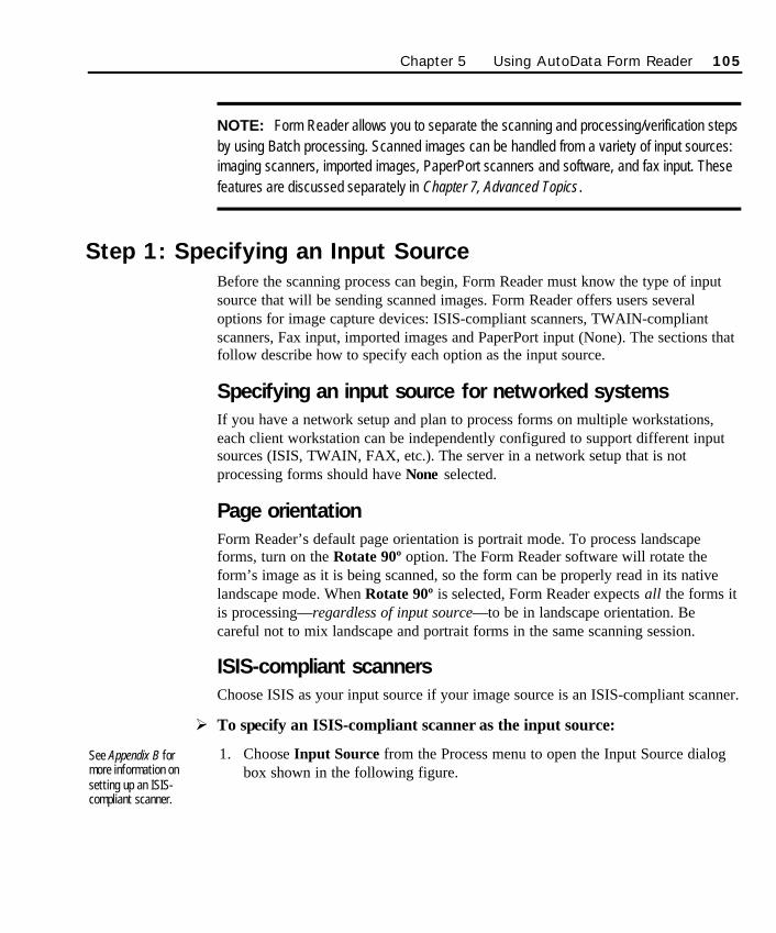
Chapter 5 Using AutoData Form Reader 105
NOTE: Form Reader allows you to separate the scanning and processing/verification stepsby using Batch processing. Scanned images can be handled from a variety of input sources:imaging scanners, imported images, PaperPort scanners and software, and fax input. Thesefeatures are discussed separately in Chapter 7, Advanced Topics.
Step 1: Specifying an Input SourceBefore the scanning process can begin, Form Reader must know the type of inputsource that will be sending scanned images. Form Reader offers users severaloptions for image capture devices: ISIS-compliant scanners, TWAIN-compliantscanners, Fax input, imported images and PaperPort input (None). The sections thatfollow describe how to specify each option as the input source.
Specifying an input source for networked systemsIf you have a network setup and plan to process forms on multiple workstations,each client workstation can be independently configured to support different inputsources (ISIS, TWAIN, FAX, etc.). The server in a network setup that is notprocessing forms should have None selected.
Page orientationForm Reader’s default page orientation is portrait mode. To process landscapeforms, turn on the Rotate 90º option. The Form Reader software will rotate theform’s image as it is being scanned, so the form can be properly read in its nativelandscape mode. When Rotate 90º is selected, Form Reader expects all the forms itis processing—regardless of input source—to be in landscape orientation. Becareful not to mix landscape and portrait forms in the same scanning session.
ISIS-compliant scannersChoose ISIS as your input source if your image source is an ISIS-compliant scanner.
Ø To specify an ISIS-compliant scanner as the input source:
1. Choose Input Source from the Process menu to open the Input Source dialogbox shown in the following figure.
See Appendix B formore information onsetting up an ISIS-compliant scanner.
SO Chapter 5 Final.qxd 3/21/00 6:26 PM Page 105
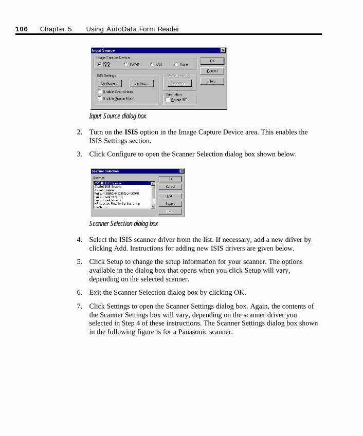
Input Source dialog box
2. Turn on the ISIS option in the Image Capture Device area. This enables theISIS Settings section.
3. Click Configure to open the Scanner Selection dialog box shown below.
Scanner Selection dialog box
4. Select the ISIS scanner driver from the list. If necessary, add a new driver byclicking Add. Instructions for adding new ISIS drivers are given below.
5. Click Setup to change the setup information for your scanner. The optionsavailable in the dialog box that opens when you click Setup will vary,depending on the selected scanner.
6. Exit the Scanner Selection dialog box by clicking OK.
7. Click Settings to open the Scanner Settings dialog box. Again, the contents ofthe Scanner Settings box will vary, depending on the scanner driver youselected in Step 4 of these instructions. The Scanner Settings dialog box shownin the following figure is for a Panasonic scanner.
106 Chapter 5 Using AutoData Form Reader
SO Chapter 5 Final.qxd 3/21/00 6:26 PM Page 106
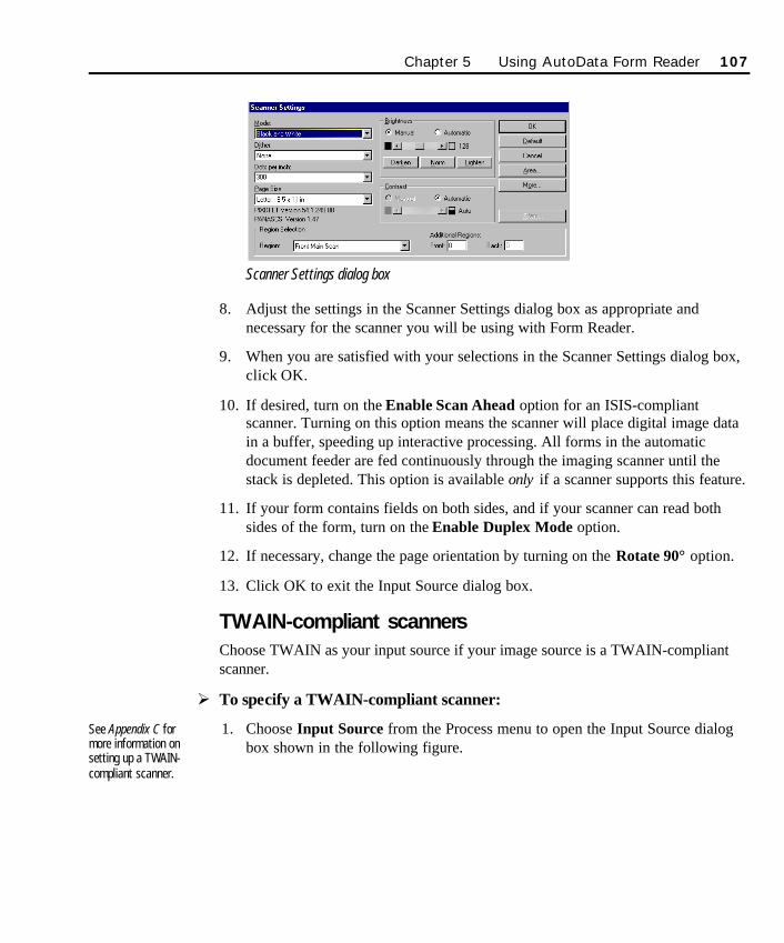
Scanner Settings dialog box
8. Adjust the settings in the Scanner Settings dialog box as appropriate andnecessary for the scanner you will be using with Form Reader.
9. When you are satisfied with your selections in the Scanner Settings dialog box,click OK.
10. If desired, turn on the Enable Scan Ahead option for an ISIS-compliantscanner. Turning on this option means the scanner will place digital image datain a buffer, speeding up interactive processing. All forms in the automaticdocument feeder are fed continuously through the imaging scanner until thestack is depleted. This option is available only if a scanner supports this feature.
11. If your form contains fields on both sides, and if your scanner can read bothsides of the form, turn on the Enable Duplex Mode option.
12. If necessary, change the page orientation by turning on the Rotate 90° option.
13. Click OK to exit the Input Source dialog box.
TWAIN-compliant scannersChoose TWAIN as your input source if your image source is a TWAIN-compliantscanner.
Ø To specify a TWAIN-compliant scanner:
1. Choose Input Source from the Process menu to open the Input Source dialogbox shown in the following figure.
See Appendix C formore information onsetting up a TWAIN-compliant scanner.
Chapter 5 Using AutoData Form Reader 107
SO Chapter 5 Final.qxd 3/21/00 6:26 PM Page 107
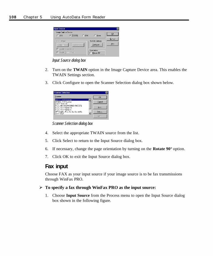
108 Chapter 5 Using AutoData Form Reader
Input Source dialog box
2. Turn on the TWAIN option in the Image Capture Device area. This enables theTWAIN Settings section.
3. Click Configure to open the Scanner Selection dialog box shown below.
Scanner Selection dialog box
4. Select the appropriate TWAIN source from the list.
5. Click Select to return to the Input Source dialog box.
6. If necessary, change the page orientation by turning on the Rotate 90° option.
7. Click OK to exit the Input Source dialog box.
Fax inputChoose FAX as your input source if your image source is to be fax transmissionsthrough WinFax PRO.
Ø To specify a fax through WinFax PRO as the input source:
1. Choose Input Source from the Process menu to open the Input Source dialogbox shown in the following figure.
SO Chapter 5 Final.qxd 3/21/00 6:26 PM Page 108
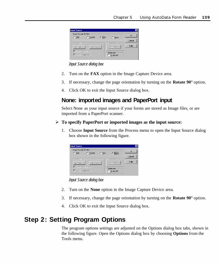
Input Source dialog box
2. Turn on the FAX option in the Image Capture Device area.
3. If necessary, change the page orientation by turning on the Rotate 90° option.
4. Click OK to exit the Input Source dialog box.
None: imported images and PaperPort inputSelect None as your input source if your forms are stored as Image files, or areimported from a PaperPort scanner.
Ø To specify PaperPort or imported images as the input source:
1. Choose Input Source from the Process menu to open the Input Source dialogbox shown in the following figure.
Input Source dialog box
2. Turn on the None option in the Image Capture Device area.
3. If necessary, change the page orientation by turning on the Rotate 90° option.
4. Click OK to exit the Input Source dialog box.
Step 2: Setting Program OptionsThe program options settings are adjusted on the Options dialog box tabs, shown inthe following figure. Open the Options dialog box by choosing Options from theTools menu.
Chapter 5 Using AutoData Form Reader 109
SO Chapter 5 Final.qxd 3/21/00 6:26 PM Page 109
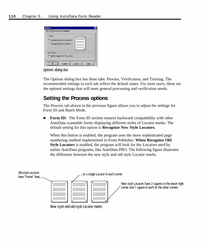
Options dialog box
The Options dialog box has three tabs: Process, Verification, and Training. Therecommended settings in each tab reflect the default states. For most users, these arethe optimal settings that will meet general processing and verification needs.
Setting the Process optionsThe Process tab shown in the previous figure allows you to adjust the settings forForm ID and Batch Mode.
n Form ID: The Form ID section ensures backward compatibility with otherAutoData scannable forms displaying different styles of Locator marks. Thedefault setting for this option is Recognize New Style Locators.
When this button is enabled, the program uses the more sophisticated pagenumbering method implemented in Form Publisher. When Recognize OldStyle Locators is enabled, the program will look for the Locators used byearlier AutoData programs, like AutoData PRO. The following figure illustratesthe difference between the new style and old style Locator marks.
New style and old style Locator marks
110 Chapter 5 Using AutoData Form Reader
New style Locators have 2 squares in the lower rightcorner and 1 square in each of the other corners
Old style Locatorshave “frame” lines…
…or a single Locator in each corner
SO Chapter 5 Final.qxd 3/21/00 6:26 PM Page 110
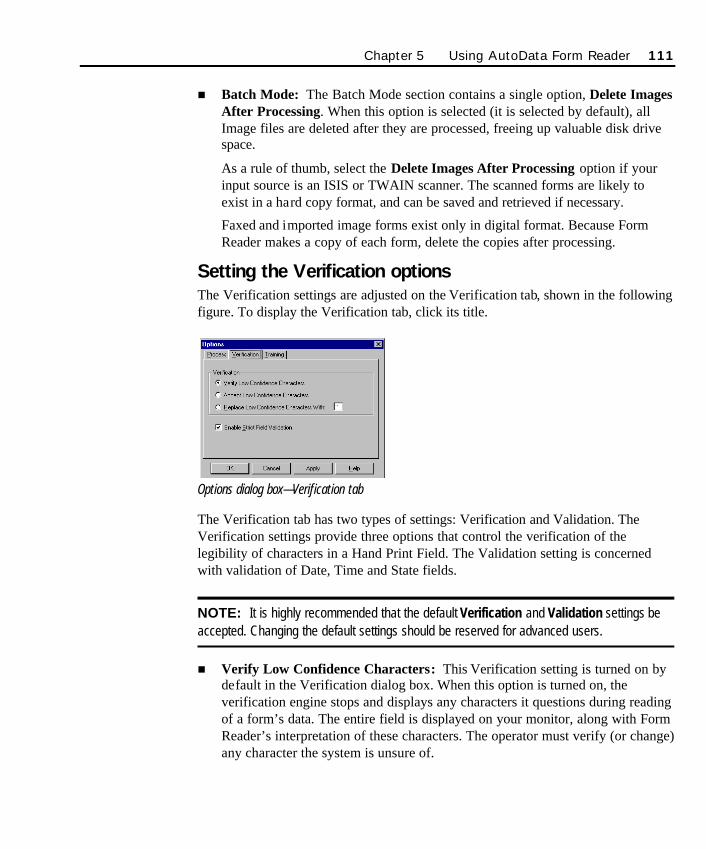
n Batch Mode: The Batch Mode section contains a single option, Delete ImagesAfter Processing. When this option is selected (it is selected by default), allImage files are deleted after they are processed, freeing up valuable disk drivespace.
As a rule of thumb, select the Delete Images After Processing option if yourinput source is an ISIS or TWAIN scanner. The scanned forms are likely toexist in a hard copy format, and can be saved and retrieved if necessary.
Faxed and imported image forms exist only in digital format. Because FormReader makes a copy of each form, delete the copies after processing.
Setting the Verification optionsThe Verification settings are adjusted on the Verification tab, shown in the followingfigure. To display the Verification tab, click its title.
Options dialog box—Verification tab
The Verification tab has two types of settings: Verification and Validation. TheVerification settings provide three options that control the verification of thelegibility of characters in a Hand Print Field. The Validation setting is concernedwith validation of Date, Time and State fields.
NOTE: It is highly recommended that the default Verification and Validation settings beaccepted. Changing the default settings should be reserved for advanced users.
n Verify Low Confidence Characters: This Verification setting is turned on bydefault in the Verification dialog box. When this option is turned on, theverification engine stops and displays any characters it questions during readingof a form’s data. The entire field is displayed on your monitor, along with FormReader’s interpretation of these characters. The operator must verify (or change)any character the system is unsure of.
Chapter 5 Using AutoData Form Reader 111
SO Chapter 5 Final.qxd 3/21/00 6:26 PM Page 111
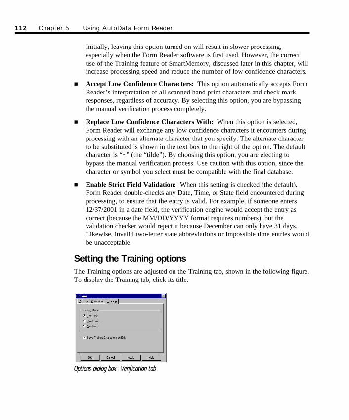
Initially, leaving this option turned on will result in slower processing,especially when the Form Reader software is first used. However, the correctuse of the Training feature of SmartMemory, discussed later in this chapter, willincrease processing speed and reduce the number of low confidence characters.
n Accept Low Confidence Characters: This option automatically accepts FormReader’s interpretation of all scanned hand print characters and check markresponses, regardless of accuracy. By selecting this option, you are bypassingthe manual verification process completely.
n Replace Low Confidence Characters With: When this option is selected,Form Reader will exchange any low confidence characters it encounters duringprocessing with an alternate character that you specify. The alternate characterto be substituted is shown in the text box to the right of the option. The defaultcharacter is “~” (the “tilde”). By choosing this option, you are electing tobypass the manual verification process. Use caution with this option, since thecharacter or symbol you select must be compatible with the final database.
n Enable Strict Field Validation: When this setting is checked (the default),Form Reader double-checks any Date, Time, or State field encountered duringprocessing, to ensure that the entry is valid. For example, if someone enters12/37/2001 in a date field, the verification engine would accept the entry ascorrect (because the MM/DD/YYYY format requires numbers), but thevalidation checker would reject it because December can only have 31 days.Likewise, invalid two-letter state abbreviations or impossible time entries wouldbe unacceptable.
Setting the Training optionsThe Training options are adjusted on the Training tab, shown in the following figure.To display the Training tab, click its title.
Options dialog box—Verification tab
112 Chapter 5 Using AutoData Form Reader
SO Chapter 5 Final.qxd 3/21/00 6:26 PM Page 112
The AutoData SmartMemory Training options control the speed at which the handprint reading engine learns character shapes over time.
As you correct read errors, or manually key enter unrecognized characters duringprocessing sessions, the SmartMemory technology gradually builds a “library” ofacceptable character shapes. When it is first used, the software recognizes only oneform of each letter, but it gradually builds a series of other possible acceptableforms for each letter. As you work with forms, you should notice an increase in formprocessing speed as fewer and fewer characters are questioned. To achievemaximum benefit from this feature, follow the recommended settings.
Ø To set the Training options:
1. Select a training option.
Choose Soft Train (default) to gradually increase the library of acceptablecharacter forms over time.
Choose Hard Train only if you are an experienced user, and want the newcharacter shapes immediately committed to memory.
Choose Disabled only if you want no new training of character shapes to takeplace.
NOTE: The default, Soft Train, should be accepted as the normal Training setting.Hard Train mode is intended for special situations and experienced users. On anetwork, the user processing the most forms should have Soft Train enabled, and allother users should check Disabled.
2. The Save Trained Characters on Exit option is the recommended setting formost users. This default updates the SmartMemory file with the newly trainedcharacters each time Form Reader is shut down. Each processing session makesthe software smarter as it adds newly learned letter shapes to the SmartMemoryfile. As more shapes are stored in the library, there are more options againstwhich to compare questionable, or low confidence, characters. As a result, theneed for operator verification is reduced, and form processing speed isincreased.
In a network environment, each user may choose training options individually,with each workstation thus keeping a copy of its learned letter shapes in its ownSmartMemory file.
If desired, turn off the Save Trained Characters on Exit option.
Chapter 5 Using AutoData Form Reader 113
SO Chapter 5 Final.qxd 3/21/00 6:26 PM Page 113
114 Chapter 5 Using AutoData Form Reader
Step 3: Scanning Your FormsOnce you have specified the input source and set the program options, you are readyto begin scanning forms.
The first time you scan a new form, you may be required to provide Form Readerwith information it needs to be able to process the information it reads from yourform. Once this information is provided (via Scannable Office Wizards, which guideyou through every step of the process), subsequent scanning sessions generallyproceed without interruption.
This section assumes the input source you specified is a scanner. Chapter 7,Advanced Topics describes the considerations specific to processing WinFax PROfiles, PaperPort and imported images.
Form scanning guidelinesScannable forms can consist of any number of form types. While Form Reader isflexible in how it scans the forms, a few rules must be observed:
n Landscape and portrait forms cannot be mixed.
n Multi-page forms must be processed as units.
n If there is a Serial Field, the pages of a single multi-page form need not be inpage order.
n If there is no Serial Field, the pages of each multi-page form must be read inexact page order.
n When the first page of a multi-page form is recognized by Form Reader, theprogram will not allow processing of another form until all the pages of thatparticular form are read (except for serialized forms).
You are now ready to begin scanning forms.
Selecting Interactive vs. Batch processingWhen you begin scanning your forms, you have two options. You can choose tocombine the scanning step with the processing of the form’s data (this is calledInteractive processing), or you can scan your forms in one step and process them inanother. The latter method is called Batch processing.
NOTE: We assume you choose Interactive processing for your scanning session. SeeChapter 7, Advanced Topics, for a more detailed explanation of Batch processing method.
SO Chapter 5 Final.qxd 3/21/00 6:26 PM Page 114
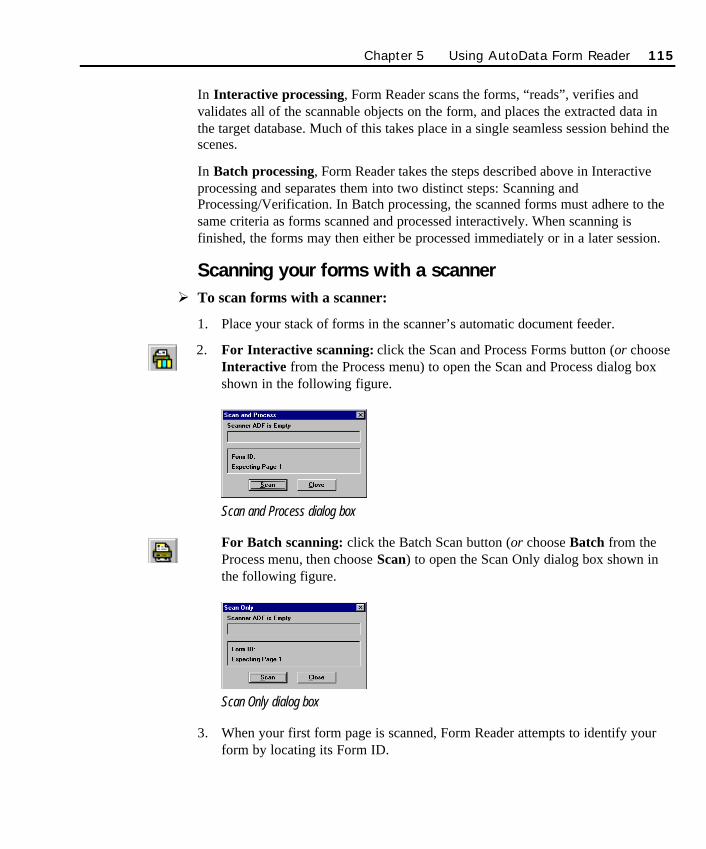
In Interactive processing, Form Reader scans the forms, “reads”, verifies andvalidates all of the scannable objects on the form, and places the extracted data inthe target database. Much of this takes place in a single seamless session behind thescenes.
In Batch processing, Form Reader takes the steps described above in Interactiveprocessing and separates them into two distinct steps: Scanning andProcessing/Verification. In Batch processing, the scanned forms must adhere to thesame criteria as forms scanned and processed interactively. When scanning isfinished, the forms may then either be processed immediately or in a later session.
Scanning your forms with a scannerØ To scan forms with a scanner:
1. Place your stack of forms in the scanner’s automatic document feeder.
2. For Interactive scanning: click the Scan and Process Forms button (or chooseInteractive from the Process menu) to open the Scan and Process dialog boxshown in the following figure.
Scan and Process dialog box
For Batch scanning: click the Batch Scan button (or choose Batch from theProcess menu, then choose Scan) to open the Scan Only dialog box shown inthe following figure.
Scan Only dialog box
3. When your first form page is scanned, Form Reader attempts to identify yourform by locating its Form ID.
Chapter 5 Using AutoData Form Reader 115
SO Chapter 5 Final.qxd 3/21/00 6:26 PM Page 115
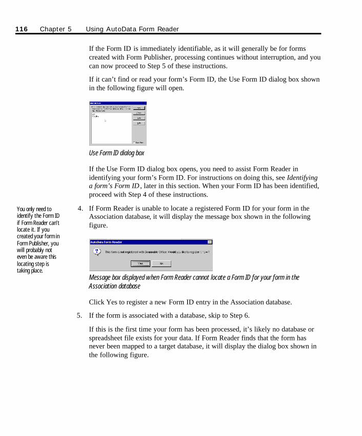
If the Form ID is immediately identifiable, as it will generally be for formscreated with Form Publisher, processing continues without interruption, and youcan now proceed to Step 5 of these instructions.
If it can’t find or read your form’s Form ID, the Use Form ID dialog box shownin the following figure will open.
Use Form ID dialog box
If the Use Form ID dialog box opens, you need to assist Form Reader inidentifying your form’s Form ID. For instructions on doing this, see Identifyinga form’s Form ID , later in this section. When your Form ID has been identified,proceed with Step 4 of these instructions.
4. If Form Reader is unable to locate a registered Form ID for your form in theAssociation database, it will display the message box shown in the followingfigure.
Message box displayed when Form Reader cannot locate a Form ID for your form in theAssociation database
Click Yes to register a new Form ID entry in the Association database.
5. If the form is associated with a database, skip to Step 6.
If this is the first time your form has been processed, it’s likely no database orspreadsheet file exists for your data. If Form Reader finds that the form hasnever been mapped to a target database, it will display the dialog box shown inthe following figure.
You only need toidentify the Form IDif Form Reader can’tlocate it. If youcreated your form inForm Publisher, youwill probably noteven be aware thislocating step istaking place.
116 Chapter 5 Using AutoData Form Reader
SO Chapter 5 Final.qxd 3/21/00 6:26 PM Page 116
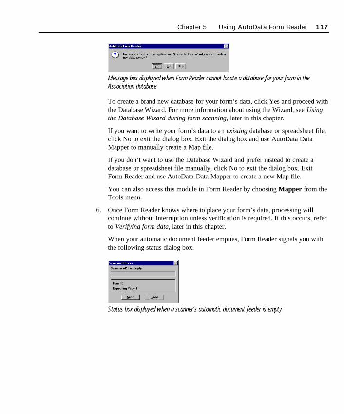
Message box displayed when Form Reader cannot locate a database for your form in theAssociation database
To create a brand new database for your form’s data, click Yes and proceed withthe Database Wizard. For more information about using the Wizard, see Usingthe Database Wizard during form scanning, later in this chapter.
If you want to write your form’s data to an existing database or spreadsheet file,click No to exit the dialog box. Exit the dialog box and use AutoData DataMapper to manually create a Map file.
If you don’t want to use the Database Wizard and prefer instead to create adatabase or spreadsheet file manually, click No to exit the dialog box. ExitForm Reader and use AutoData Data Mapper to create a new Map file.
You can also access this module in Form Reader by choosing Mapper from theTools menu.
6. Once Form Reader knows where to place your form’s data, processing willcontinue without interruption unless verification is required. If this occurs, referto Verifying form data, later in this chapter.
When your automatic document feeder empties, Form Reader signals you withthe following status dialog box.
Status box displayed when a scanner’s automatic document feeder is empty
Chapter 5 Using AutoData Form Reader 117
SO Chapter 5 Final.qxd 3/21/00 6:26 PM Page 117
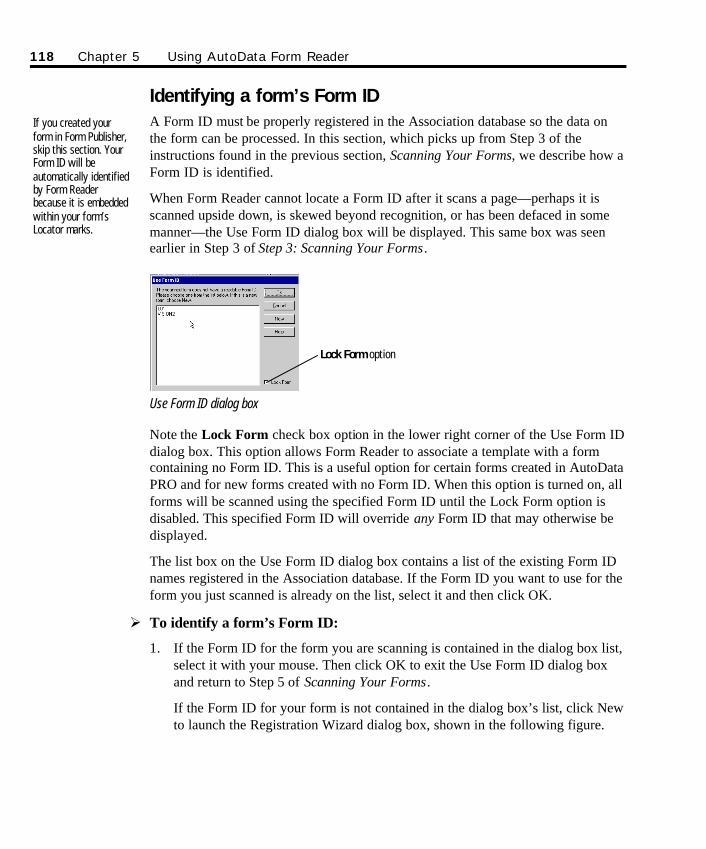
Identifying a form’s Form ID A Form ID must be properly registered in the Association database so the data onthe form can be processed. In this section, which picks up from Step 3 of theinstructions found in the previous section, Scanning Your Forms, we describe how aForm ID is identified.
When Form Reader cannot locate a Form ID after it scans a page—perhaps it isscanned upside down, is skewed beyond recognition, or has been defaced in somemanner—the Use Form ID dialog box will be displayed. This same box was seenearlier in Step 3 of Step 3: Scanning Your Forms.
Use Form ID dialog box
Note the Lock Form check box option in the lower right corner of the Use Form IDdialog box. This option allows Form Reader to associate a template with a formcontaining no Form ID. This is a useful option for certain forms created in AutoDataPRO and for new forms created with no Form ID. When this option is turned on, allforms will be scanned using the specified Form ID until the Lock Form option isdisabled. This specified Form ID will override any Form ID that may otherwise bedisplayed.
The list box on the Use Form ID dialog box contains a list of the existing Form IDnames registered in the Association database. If the Form ID you want to use for theform you just scanned is already on the list, select it and then click OK.
Ø To identify a form’s Form ID:
1. If the Form ID for the form you are scanning is contained in the dialog box list,select it with your mouse. Then click OK to exit the Use Form ID dialog boxand return to Step 5 of Scanning Your Forms.
If the Form ID for your form is not contained in the dialog box’s list, click Newto launch the Registration Wizard dialog box, shown in the following figure.
If you created yourform in Form Publisher,skip this section. YourForm ID will beautomatically identifiedby Form Readerbecause it is embeddedwithin your form’sLocator marks.
118 Chapter 5 Using AutoData Form Reader
Lock Form option
SO Chapter 5 Final.qxd 3/21/00 6:26 PM Page 118
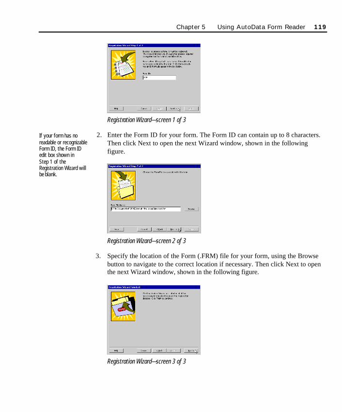
Registration Wizard—screen 1 of 3
2. Enter the Form ID for your form. The Form ID can contain up to 8 characters.Then click Next to open the next Wizard window, shown in the followingfigure.
Registration Wizard—screen 2 of 3
3. Specify the location of the Form (.FRM) file for your form, using the Browsebutton to navigate to the correct location if necessary. Then click Next to openthe next Wizard window, shown in the following figure.
Registration Wizard—screen 3 of 3
If your form has noreadable or recognizableForm ID, the Form IDedit box shown in Step 1 of theRegistration Wizard willbe blank.
Chapter 5 Using AutoData Form Reader 119
SO Chapter 5 Final.qxd 3/21/00 6:26 PM Page 119
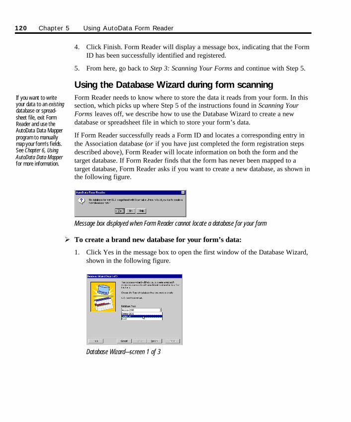
4. Click Finish. Form Reader will display a message box, indicating that the FormID has been successfully identified and registered.
5. From here, go back to Step 3: Scanning Your Forms and continue with Step 5.
Using the Database Wizard during form scanningForm Reader needs to know where to store the data it reads from your form. In thissection, which picks up where Step 5 of the instructions found in Scanning YourForms leaves off, we describe how to use the Database Wizard to create a newdatabase or spreadsheet file in which to store your form’s data.
If Form Reader successfully reads a Form ID and locates a corresponding entry inthe Association database (or if you have just completed the form registration stepsdescribed above), Form Reader will locate information on both the form and thetarget database. If Form Reader finds that the form has never been mapped to atarget database, Form Reader asks if you want to create a new database, as shown inthe following figure.
Message box displayed when Form Reader cannot locate a database for your form
Ø To create a brand new database for your form’s data:
1. Click Yes in the message box to open the first window of the Database Wizard,shown in the following figure.
Database Wizard—screen 1 of 3
If you want to writeyour data to an existingdatabase or spread-sheet file, exit FormReader and use theAutoData Data Mapperprogram to manuallymap your form’s fields.See Chapter 6, UsingAutoData Data Mapperfor more information.
120 Chapter 5 Using AutoData Form Reader
SO Chapter 5 Final.qxd 3/21/00 6:26 PM Page 120
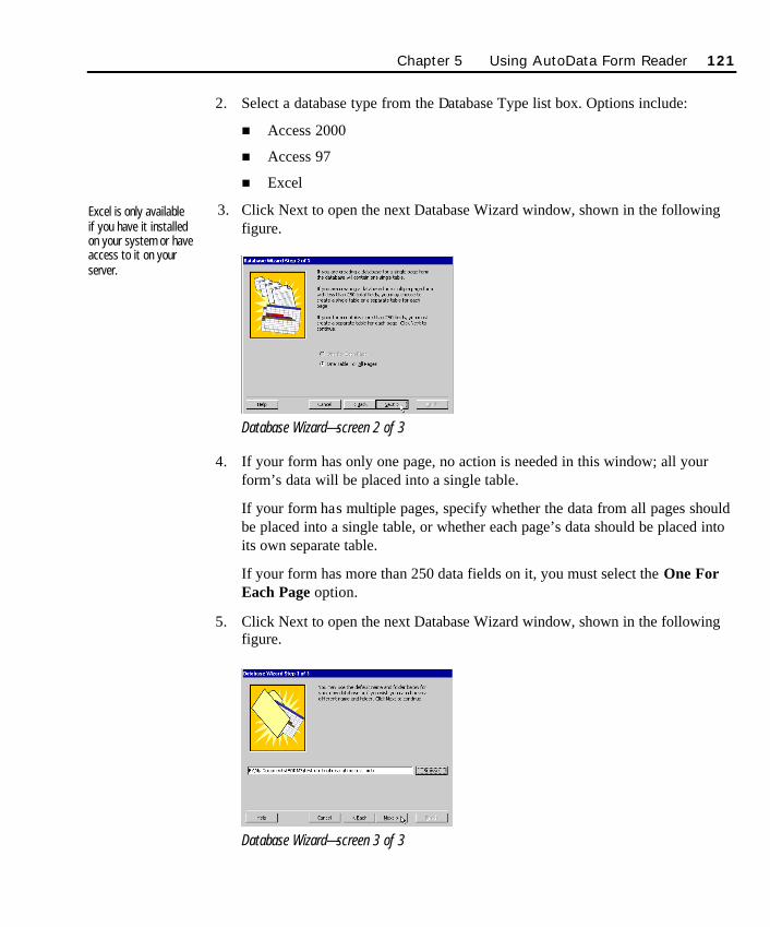
2. Select a database type from the Database Type list box. Options include:
n Access 2000
n Access 97
n Excel
3. Click Next to open the next Database Wizard window, shown in the followingfigure.
Database Wizard—screen 2 of 3
4. If your form has only one page, no action is needed in this window; all yourform’s data will be placed into a single table.
If your form has multiple pages, specify whether the data from all pages shouldbe placed into a single table, or whether each page’s data should be placed intoits own separate table.
If your form has more than 250 data fields on it, you must select the One ForEach Page option.
5. Click Next to open the next Database Wizard window, shown in the followingfigure.
Database Wizard—screen 3 of 3
Excel is only availableif you have it installedon your system or haveaccess to it on yourserver.
Chapter 5 Using AutoData Form Reader 121
SO Chapter 5 Final.qxd 3/21/00 6:26 PM Page 121
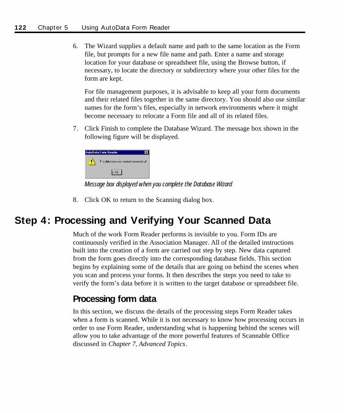
6. The Wizard supplies a default name and path to the same location as the Formfile, but prompts for a new file name and path. Enter a name and storagelocation for your database or spreadsheet file, using the Browse button, ifnecessary, to locate the directory or subdirectory where your other files for theform are kept.
For file management purposes, it is advisable to keep all your form documentsand their related files together in the same directory. You should also use similarnames for the form’s files, especially in network environments where it mightbecome necessary to relocate a Form file and all of its related files.
7. Click Finish to complete the Database Wizard. The message box shown in thefollowing figure will be displayed.
Message box displayed when you complete the Database Wizard
8. Click OK to return to the Scanning dialog box.
Step 4: Processing and Verifying Your Scanned DataMuch of the work Form Reader performs is invisible to you. Form IDs arecontinuously verified in the Association Manager. All of the detailed instructionsbuilt into the creation of a form are carried out step by step. New data capturedfrom the form goes directly into the corresponding database fields. This sectionbegins by explaining some of the details that are going on behind the scenes whenyou scan and process your forms. It then describes the steps you need to take toverify the form’s data before it is written to the target database or spreadsheet file.
Processing form dataIn this section, we discuss the details of the processing steps Form Reader takeswhen a form is scanned. While it is not necessary to know how processing occurs inorder to use Form Reader, understanding what is happening behind the scenes willallow you to take advantage of the more powerful features of Scannable Officediscussed in Chapter 7, Advanced Topics.
122 Chapter 5 Using AutoData Form Reader
SO Chapter 5 Final.qxd 3/21/00 6:26 PM Page 122
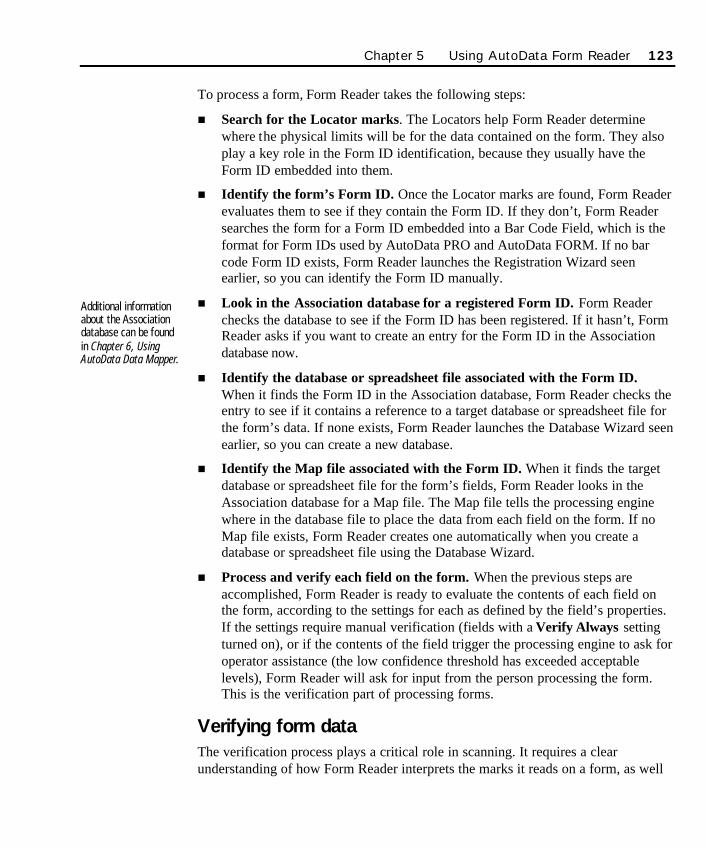
To process a form, Form Reader takes the following steps:
n Search for the Locator marks. The Locators help Form Reader determinewhere the physical limits will be for the data contained on the form. They alsoplay a key role in the Form ID identification, because they usually have theForm ID embedded into them.
n Identify the form’s Form ID. Once the Locator marks are found, Form Readerevaluates them to see if they contain the Form ID. If they don’t, Form Readersearches the form for a Form ID embedded into a Bar Code Field, which is theformat for Form IDs used by AutoData PRO and AutoData FORM. If no barcode Form ID exists, Form Reader launches the Registration Wizard seenearlier, so you can identify the Form ID manually.
n Look in the Association database for a registered Form ID. Form Readerchecks the database to see if the Form ID has been registered. If it hasn’t, FormReader asks if you want to create an entry for the Form ID in the Associationdatabase now.
n Identify the database or spreadsheet file associated with the Form ID.When it finds the Form ID in the Association database, Form Reader checks theentry to see if it contains a reference to a target database or spreadsheet file forthe form’s data. If none exists, Form Reader launches the Database Wizard seenearlier, so you can create a new database.
n Identify the Map file associated with the Form ID. When it finds the targetdatabase or spreadsheet file for the form’s fields, Form Reader looks in theAssociation database for a Map file. The Map file tells the processing enginewhere in the database file to place the data from each field on the form. If noMap file exists, Form Reader creates one automatically when you create adatabase or spreadsheet file using the Database Wizard.
n Process and verify each field on the form. When the previous steps areaccomplished, Form Reader is ready to evaluate the contents of each field onthe form, according to the settings for each as defined by the field’s properties.If the settings require manual verification (fields with a Verify Always settingturned on), or if the contents of the field trigger the processing engine to ask foroperator assistance (the low confidence threshold has exceeded acceptablelevels), Form Reader will ask for input from the person processing the form.This is the verification part of processing forms.
Verifying form dataThe verification process plays a critical role in scanning. It requires a clearunderstanding of how Form Reader interprets the marks it reads on a form, as well
Additional informationabout the Associationdatabase can be foundin Chapter 6, UsingAutoData Data Mapper.
Chapter 5 Using AutoData Form Reader 123
SO Chapter 5 Final.qxd 3/21/00 6:26 PM Page 123
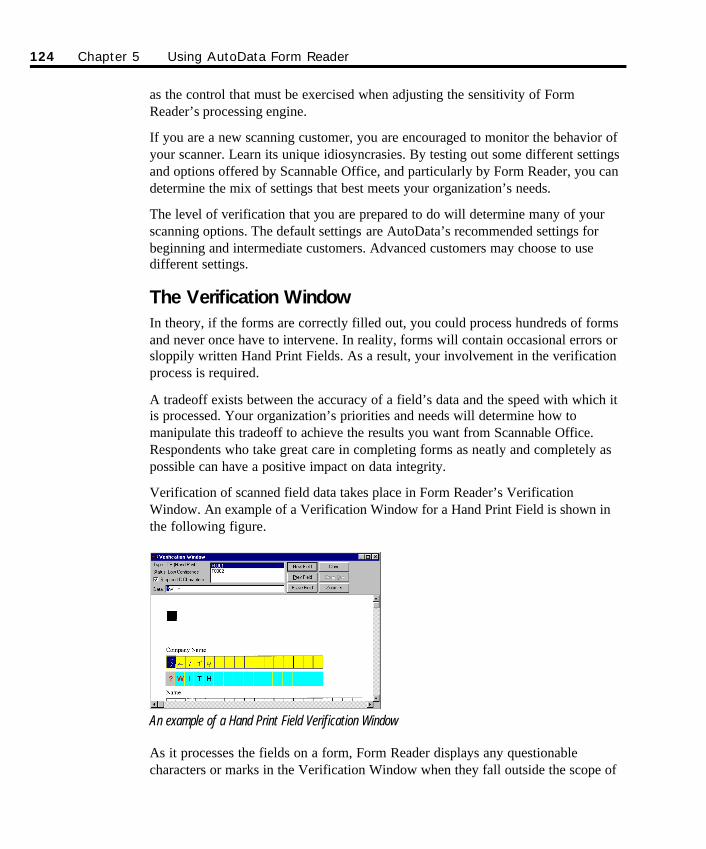
as the control that must be exercised when adjusting the sensitivity of FormReader’s processing engine.
If you are a new scanning customer, you are encouraged to monitor the behavior ofyour scanner. Learn its unique idiosyncrasies. By testing out some different settingsand options offered by Scannable Office, and particularly by Form Reader, you candetermine the mix of settings that best meets your organization’s needs.
The level of verification that you are prepared to do will determine many of yourscanning options. The default settings are AutoData’s recommended settings forbeginning and intermediate customers. Advanced customers may choose to usedifferent settings.
The Verification WindowIn theory, if the forms are correctly filled out, you could process hundreds of formsand never once have to intervene. In reality, forms will contain occasional errors orsloppily written Hand Print Fields. As a result, your involvement in the verificationprocess is required.
A tradeoff exists between the accuracy of a field’s data and the speed with which itis processed. Your organization’s priorities and needs will determine how tomanipulate this tradeoff to achieve the results you want from Scannable Office.Respondents who take great care in completing forms as neatly and completely aspossible can have a positive impact on data integrity.
Verification of scanned field data takes place in Form Reader’s VerificationWindow. An example of a Verification Window for a Hand Print Field is shown inthe following figure.
An example of a Hand Print Field Verification Window
As it processes the fields on a form, Form Reader displays any questionablecharacters or marks in the Verification Window when they fall outside the scope of
124 Chapter 5 Using AutoData Form Reader
SO Chapter 5 Final.qxd 3/21/00 6:26 PM Page 124
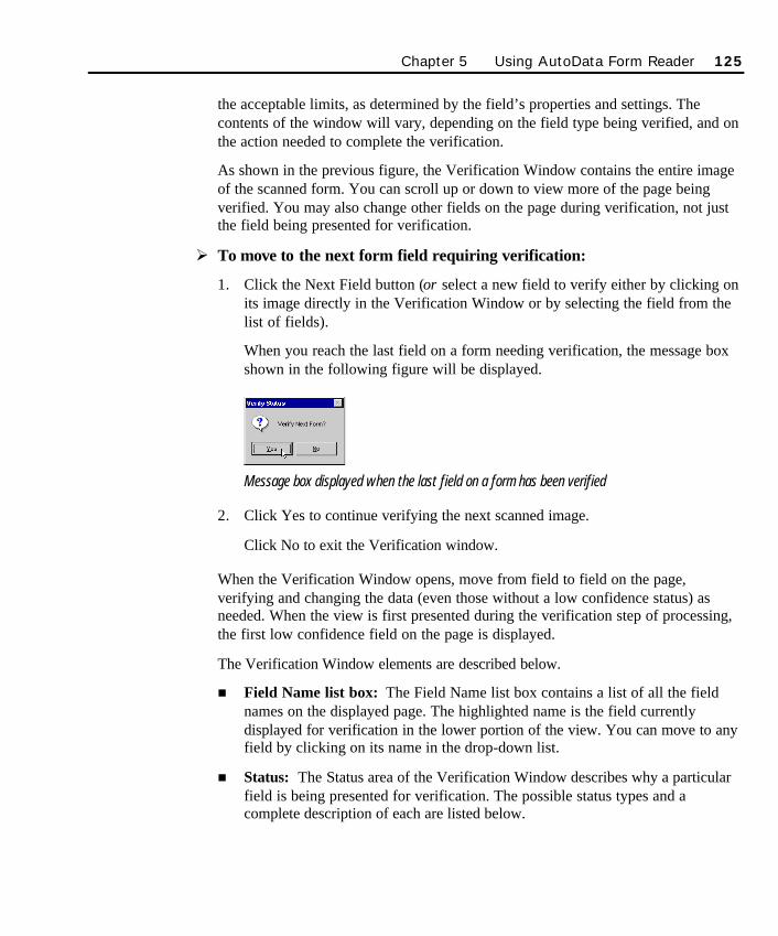
the acceptable limits, as determined by the field’s properties and settings. Thecontents of the window will vary, depending on the field type being verified, and onthe action needed to complete the verification.
As shown in the previous figure, the Verification Window contains the entire imageof the scanned form. You can scroll up or down to view more of the page beingverified. You may also change other fields on the page during verification, not justthe field being presented for verification.
Ø To move to the next form field requiring verification:
1. Click the Next Field button (or select a new field to verify either by clicking onits image directly in the Verification Window or by selecting the field from thelist of fields).
When you reach the last field on a form needing verification, the message boxshown in the following figure will be displayed.
Message box displayed when the last field on a form has been verified
2. Click Yes to continue verifying the next scanned image.
Click No to exit the Verification window.
When the Verification Window opens, move from field to field on the page,verifying and changing the data (even those without a low confidence status) asneeded. When the view is first presented during the verification step of processing,the first low confidence field on the page is displayed.
The Verification Window elements are described below.
n Field Name list box: The Field Name list box contains a list of all the fieldnames on the displayed page. The highlighted name is the field currentlydisplayed for verification in the lower portion of the view. You can move to anyfield by clicking on its name in the drop-down list.
n Status: The Status area of the Verification Window describes why a particularfield is being presented for verification. The possible status types and acomplete description of each are listed below.
Chapter 5 Using AutoData Form Reader 125
SO Chapter 5 Final.qxd 3/21/00 6:26 PM Page 125
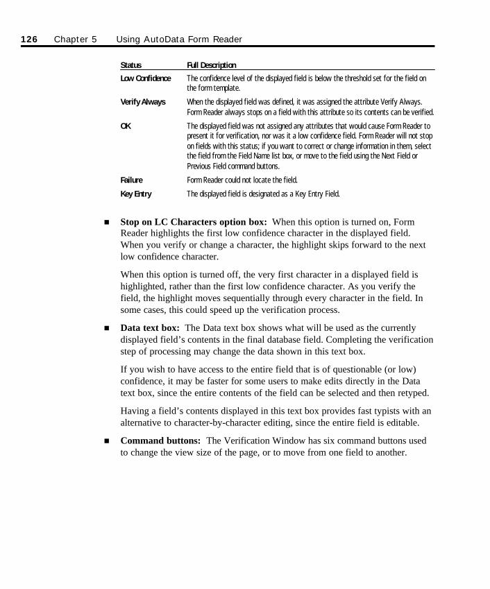
Status Full Description
Low Confidence The confidence level of the displayed field is below the threshold set for the field onthe form template.
Verify Always When the displayed field was defined, it was assigned the attribute Verify Always.Form Reader always stops on a field with this attribute so its contents can be verified.
OK The displayed field was not assigned any attributes that would cause Form Reader topresent it for verification, nor was it a low confidence field. Form Reader will not stopon fields with this status; if you want to correct or change information in them, selectthe field from the Field Name list box, or move to the field using the Next Field orPrevious Field command buttons.
Failure Form Reader could not locate the field.
Key Entry The displayed field is designated as a Key Entry Field.
n Stop on LC Characters option box: When this option is turned on, FormReader highlights the first low confidence character in the displayed field.When you verify or change a character, the highlight skips forward to the nextlow confidence character.
When this option is turned off, the very first character in a displayed field ishighlighted, rather than the first low confidence character. As you verify thefield, the highlight moves sequentially through every character in the field. Insome cases, this could speed up the verification process.
n Data text box: The Data text box shows what will be used as the currentlydisplayed field’s contents in the final database field. Completing the verificationstep of processing may change the data shown in this text box.
If you wish to have access to the entire field that is of questionable (or low)confidence, it may be faster for some users to make edits directly in the Datatext box, since the entire contents of the field can be selected and then retyped.
Having a field’s contents displayed in this text box provides fast typists with analternative to character-by-character editing, since the entire field is editable.
n Command buttons: The Verification Window has six command buttons usedto change the view size of the page, or to move from one field to another.
126 Chapter 5 Using AutoData Form Reader
SO Chapter 5 Final.qxd 3/21/00 6:26 PM Page 126
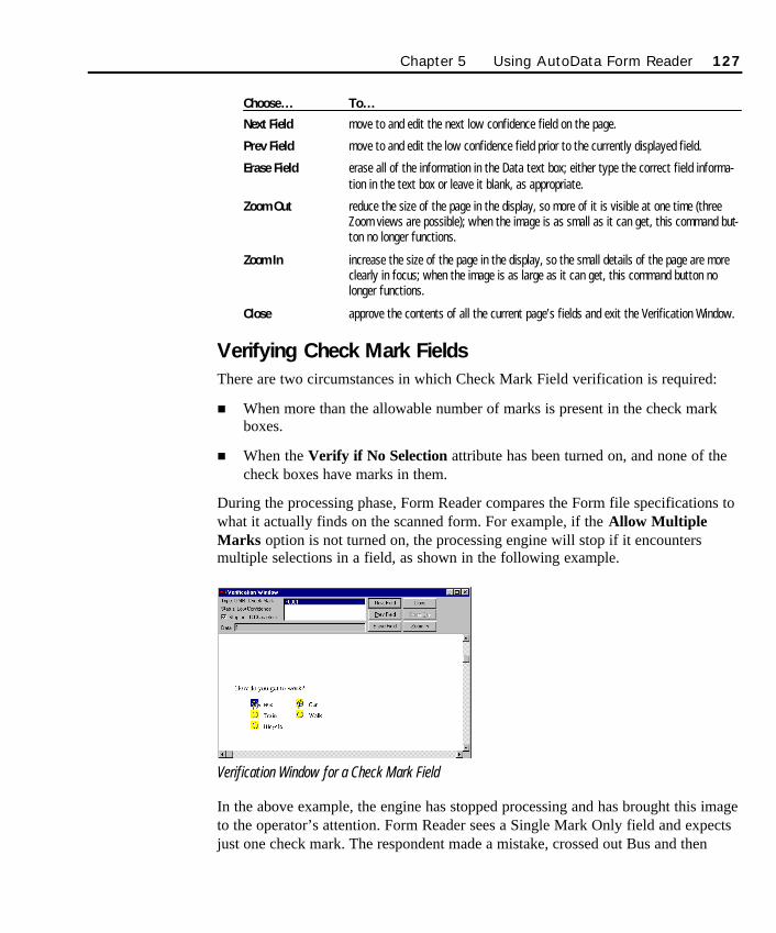
Choose… To…
Next Field move to and edit the next low confidence field on the page.
Prev Field move to and edit the low confidence field prior to the currently displayed field.
Erase Field erase all of the information in the Data text box; either type the correct field informa-tion in the text box or leave it blank, as appropriate.
Zoom Out reduce the size of the page in the display, so more of it is visible at one time (threeZoom views are possible); when the image is as small as it can get, this command but-ton no longer functions.
Zoom In increase the size of the page in the display, so the small details of the page are moreclearly in focus; when the image is as large as it can get, this command button nolonger functions.
Close approve the contents of all the current page’s fields and exit the Verification Window.
Verifying Check Mark FieldsThere are two circumstances in which Check Mark Field verification is required:
n When more than the allowable number of marks is present in the check markboxes.
n When the Verify if No Selection attribute has been turned on, and none of thecheck boxes have marks in them.
During the processing phase, Form Reader compares the Form file specifications towhat it actually finds on the scanned form. For example, if the Allow MultipleMarks option is not turned on, the processing engine will stop if it encountersmultiple selections in a field, as shown in the following example.
Verification Window for a Check Mark Field
In the above example, the engine has stopped processing and has brought this imageto the operator’s attention. Form Reader sees a Single Mark Only field and expectsjust one check mark. The respondent made a mistake, crossed out Bus and then
Chapter 5 Using AutoData Form Reader 127
SO Chapter 5 Final.qxd 3/21/00 6:26 PM Page 127
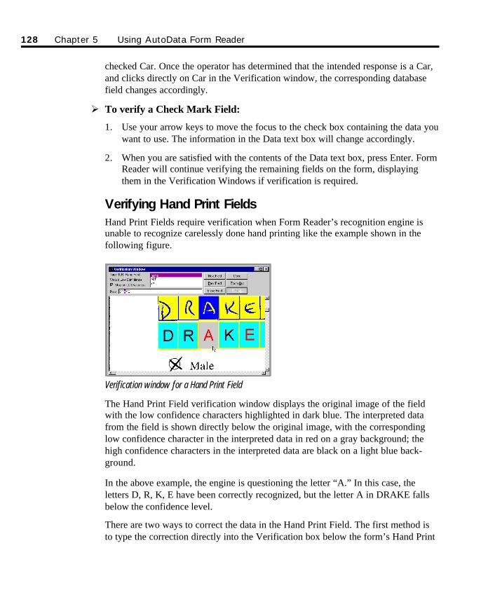
checked Car. Once the operator has determined that the intended response is a Car,and clicks directly on Car in the Verification window, the corresponding databasefield changes accordingly.
Ø To verify a Check Mark Field:
1. Use your arrow keys to move the focus to the check box containing the data youwant to use. The information in the Data text box will change accordingly.
2. When you are satisfied with the contents of the Data text box, press Enter. FormReader will continue verifying the remaining fields on the form, displayingthem in the Verification Windows if verification is required.
Verifying Hand Print FieldsHand Print Fields require verification when Form Reader’s recognition engine isunable to recognize carelessly done hand printing like the example shown in thefollowing figure.
Verification window for a Hand Print Field
The Hand Print Field verification window displays the original image of the fieldwith the low confidence characters highlighted in dark blue. The interpreted datafrom the field is shown directly below the original image, with the correspondinglow confidence character in the interpreted data in red on a gray background; thehigh confidence characters in the interpreted data are black on a light blue back-ground.
In the above example, the engine is questioning the letter “A.” In this case, theletters D, R, K, E have been correctly recognized, but the letter A in DRAKE fallsbelow the confidence level.
There are two ways to correct the data in the Hand Print Field. The first method isto type the correction directly into the Verification box below the form’s Hand Print
128 Chapter 5 Using AutoData Form Reader
SO Chapter 5 Final.qxd 3/21/00 6:26 PM Page 128
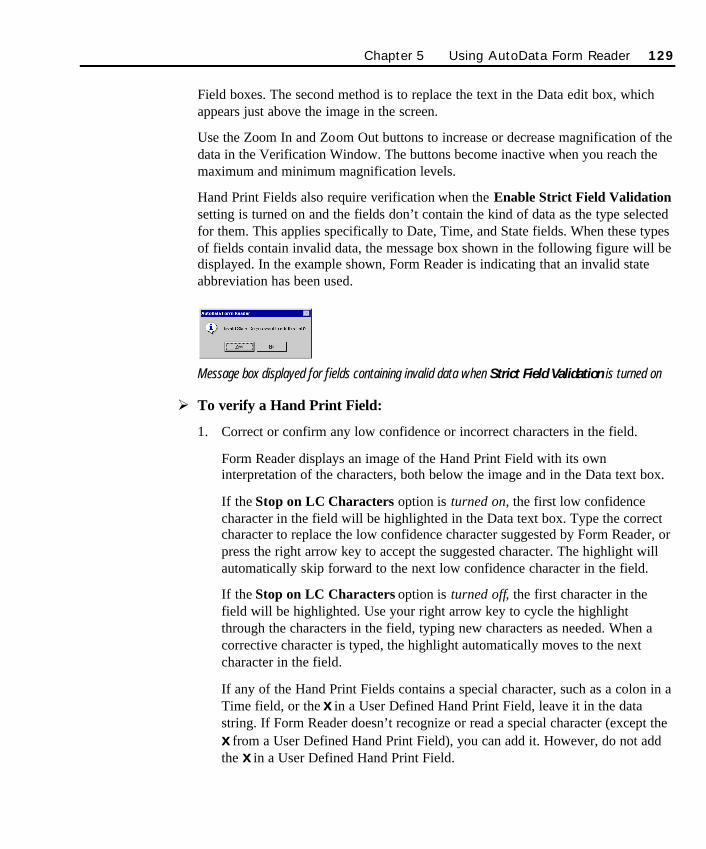
Field boxes. The second method is to replace the text in the Data edit box, whichappears just above the image in the screen.
Use the Zoom In and Zoom Out buttons to increase or decrease magnification of thedata in the Verification Window. The buttons become inactive when you reach themaximum and minimum magnification levels.
Hand Print Fields also require verification when the Enable Strict Field Validationsetting is turned on and the fields don’t contain the kind of data as the type selectedfor them. This applies specifically to Date, Time, and State fields. When these typesof fields contain invalid data, the message box shown in the following figure will bedisplayed. In the example shown, Form Reader is indicating that an invalid stateabbreviation has been used.
Message box displayed for fields containing invalid data when Strict Field Validation is turned on
Ø To verify a Hand Print Field:
1. Correct or confirm any low confidence or incorrect characters in the field.
Form Reader displays an image of the Hand Print Field with its owninterpretation of the characters, both below the image and in the Data text box.
If the Stop on LC Characters option is turned on, the first low confidencecharacter in the field will be highlighted in the Data text box. Type the correctcharacter to replace the low confidence character suggested by Form Reader, orpress the right arrow key to accept the suggested character. The highlight willautomatically skip forward to the next low confidence character in the field.
If the Stop on LC Characters option is turned off, the first character in thefield will be highlighted. Use your right arrow key to cycle the highlightthrough the characters in the field, typing new characters as needed. When acorrective character is typed, the highlight automatically moves to the nextcharacter in the field.
If any of the Hand Print Fields contains a special character, such as a colon in aTime field, or the x in a User Defined Hand Print Field, leave it in the datastring. If Form Reader doesn’t recognize or read a special character (except thex from a User Defined Hand Print Field), you can add it. However, do not addthe x in a User Defined Hand Print Field.
Chapter 5 Using AutoData Form Reader 129
SO Chapter 5 Final.qxd 3/21/00 6:26 PM Page 129
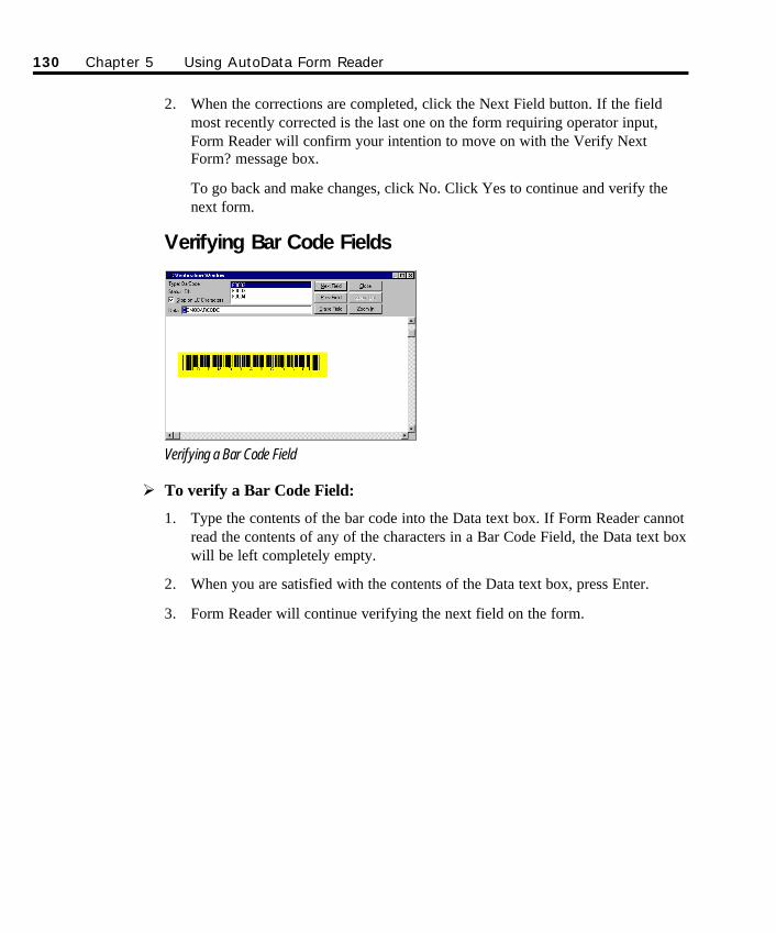
2. When the corrections are completed, click the Next Field button. If the fieldmost recently corrected is the last one on the form requiring operator input,Form Reader will confirm your intention to move on with the Verify NextForm? message box.
To go back and make changes, click No. Click Yes to continue and verify thenext form.
Verifying Bar Code Fields
Verifying a Bar Code Field
Ø To verify a Bar Code Field:
1. Type the contents of the bar code into the Data text box. If Form Reader cannotread the contents of any of the characters in a Bar Code Field, the Data text boxwill be left completely empty.
2. When you are satisfied with the contents of the Data text box, press Enter.
3. Form Reader will continue verifying the next field on the form.
130 Chapter 5 Using AutoData Form Reader
SO Chapter 5 Final.qxd 3/21/00 6:26 PM Page 130
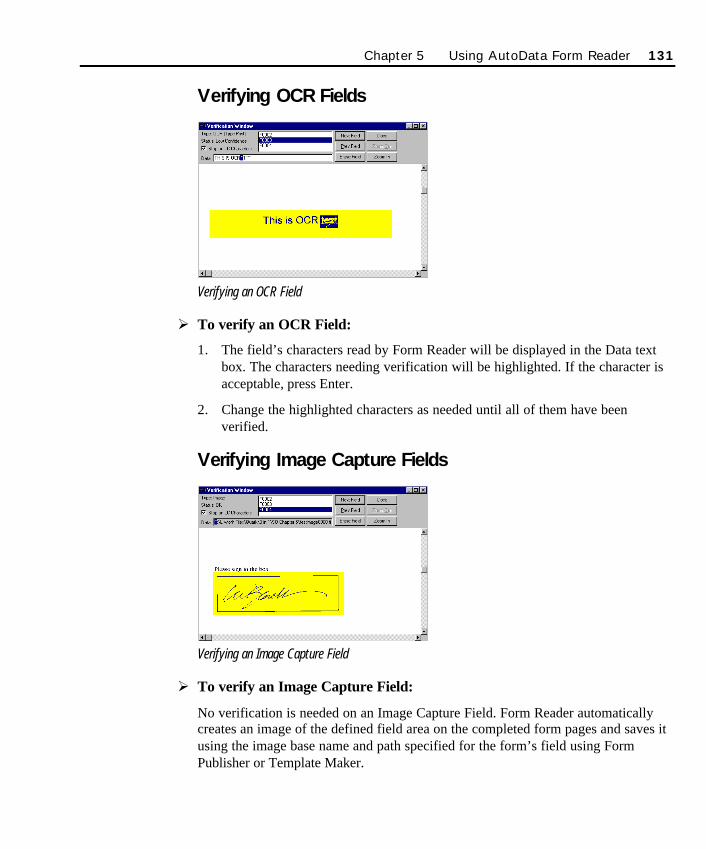
Verifying OCR Fields
Verifying an OCR Field
Ø To verify an OCR Field:
1. The field’s characters read by Form Reader will be displayed in the Data textbox. The characters needing verification will be highlighted. If the character isacceptable, press Enter.
2. Change the highlighted characters as needed until all of them have beenverified.
Verifying Image Capture Fields
Verifying an Image Capture Field
Ø To verify an Image Capture Field:
No verification is needed on an Image Capture Field. Form Reader automaticallycreates an image of the defined field area on the completed form pages and saves itusing the image base name and path specified for the form’s field using FormPublisher or Template Maker.
Chapter 5 Using AutoData Form Reader 131
SO Chapter 5 Final.qxd 3/21/00 6:26 PM Page 131
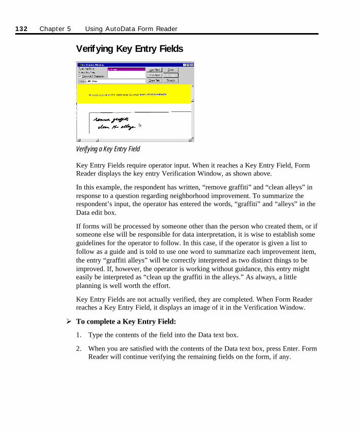
Verifying Key Entry Fields
Verifying a Key Entry Field
Key Entry Fields require operator input. When it reaches a Key Entry Field, FormReader displays the key entry Verification Window, as shown above.
In this example, the respondent has written, “remove graffiti” and “clean alleys” inresponse to a question regarding neighborhood improvement. To summarize therespondent’s input, the operator has entered the words, “graffiti” and “alleys” in theData edit box.
If forms will be processed by someone other than the person who created them, or ifsomeone else will be responsible for data interpretation, it is wise to establish someguidelines for the operator to follow. In this case, if the operator is given a list tofollow as a guide and is told to use one word to summarize each improvement item,the entry “graffiti alleys” will be correctly interpreted as two distinct things to beimproved. If, however, the operator is working without guidance, this entry mighteasily be interpreted as “clean up the graffiti in the alleys.” As always, a littleplanning is well worth the effort.
Key Entry Fields are not actually verified, they are completed. When Form Readerreaches a Key Entry Field, it displays an image of it in the Verification Window.
Ø To complete a Key Entry Field:
1. Type the contents of the field into the Data text box.
2. When you are satisfied with the contents of the Data text box, press Enter. FormReader will continue verifying the remaining fields on the form, if any.
132 Chapter 5 Using AutoData Form Reader
SO Chapter 5 Final.qxd 3/21/00 6:26 PM Page 132
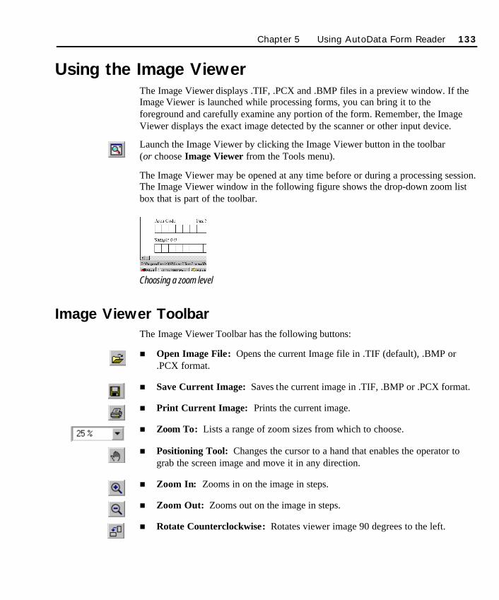
Using the Image ViewerThe Image Viewer displays .TIF, .PCX and .BMP files in a preview window. If theImage Viewer is launched while processing forms, you can bring it to theforeground and carefully examine any portion of the form. Remember, the ImageViewer displays the exact image detected by the scanner or other input device.
Launch the Image Viewer by clicking the Image Viewer button in the toolbar (or choose Image Viewer from the Tools menu).
The Image Viewer may be opened at any time before or during a processing session.The Image Viewer window in the following figure shows the drop-down zoom listbox that is part of the toolbar.
Choosing a zoom level
Image Viewer ToolbarThe Image Viewer Toolbar has the following buttons:
n Open Image File: Opens the current Image file in .TIF (default), .BMP or.PCX format.
n Save Current Image: Saves the current image in .TIF, .BMP or .PCX format.
n Print Current Image: Prints the current image.
n Zoom To: Lists a range of zoom sizes from which to choose.
n Positioning Tool: Changes the cursor to a hand that enables the operator tograb the screen image and move it in any direction.
n Zoom In: Zooms in on the image in steps.
n Zoom Out: Zooms out on the image in steps.
n Rotate Counterclockwise: Rotates viewer image 90 degrees to the left.
Chapter 5 Using AutoData Form Reader 133
SO Chapter 5 Final.qxd 3/21/00 6:26 PM Page 133
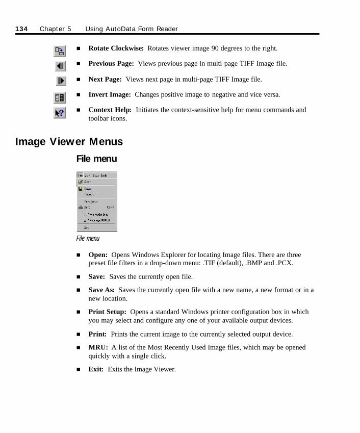
n Rotate Clockwise: Rotates viewer image 90 degrees to the right.
n Previous Page: Views previous page in multi-page TIFF Image file.
n Next Page: Views next page in multi-page TIFF Image file.
n Invert Image: Changes positive image to negative and vice versa.
n Context Help: Initiates the context-sensitive help for menu commands andtoolbar icons.
Image Viewer Menus
File menu
File menu
n Open: Opens Windows Explorer for locating Image files. There are threepreset file filters in a drop-down menu: .TIF (default), .BMP and .PCX.
n Save: Saves the currently open file.
n Save As: Saves the currently open file with a new name, a new format or in anew location.
n Print Setup: Opens a standard Windows printer configuration box in whichyou may select and configure any one of your available output devices.
n Print: Prints the current image to the currently selected output device.
n MRU: A list of the Most Recently Used Image files, which may be openedquickly with a single click.
n Exit: Exits the Image Viewer.
134 Chapter 5 Using AutoData Form Reader
SO Chapter 5 Final.qxd 3/21/00 6:26 PM Page 134
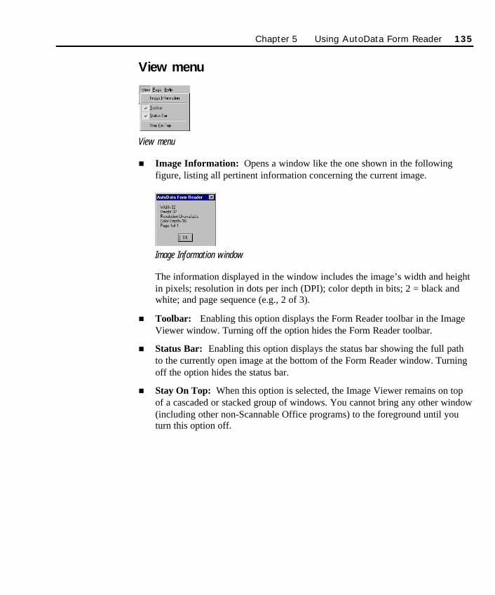
View menu
View menu
n Image Information: Opens a window like the one shown in the followingfigure, listing all pertinent information concerning the current image.
Image Information window
The information displayed in the window includes the image’s width and heightin pixels; resolution in dots per inch (DPI); color depth in bits; 2 = black andwhite; and page sequence (e.g., 2 of 3).
n Toolbar: Enabling this option displays the Form Reader toolbar in the ImageViewer window. Turning off the option hides the Form Reader toolbar.
n Status Bar: Enabling this option displays the status bar showing the full pathto the currently open image at the bottom of the Form Reader window. Turningoff the option hides the status bar.
n Stay On Top: When this option is selected, the Image Viewer remains on topof a cascaded or stacked group of windows. You cannot bring any other window(including other non-Scannable Office programs) to the foreground until youturn this option off.
Chapter 5 Using AutoData Form Reader 135
SO Chapter 5 Final.qxd 3/21/00 6:26 PM Page 135
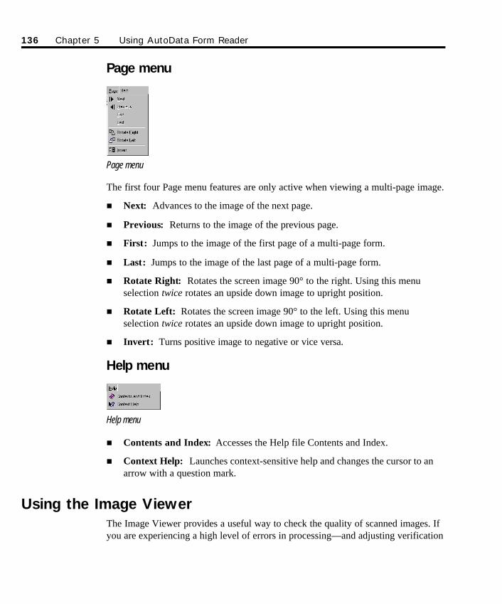
Page menu
Page menu
The first four Page menu features are only active when viewing a multi-page image.
n Next: Advances to the image of the next page.
n Previous: Returns to the image of the previous page.
n First: Jumps to the image of the first page of a multi-page form.
n Last: Jumps to the image of the last page of a multi-page form.
n Rotate Right: Rotates the screen image 90° to the right. Using this menuselection twice rotates an upside down image to upright position.
n Rotate Left: Rotates the screen image 90° to the left. Using this menuselection twice rotates an upside down image to upright position.
n Invert: Turns positive image to negative or vice versa.
Help menu
Help menu
n Contents and Index: Accesses the Help file Contents and Index.
n Context Help: Launches context-sensitive help and changes the cursor to anarrow with a question mark.
Using the Image ViewerThe Image Viewer provides a useful way to check the quality of scanned images. Ifyou are experiencing a high level of errors in processing—and adjusting verification
136 Chapter 5 Using AutoData Form Reader
SO Chapter 5 Final.qxd 3/21/00 6:26 PM Page 136
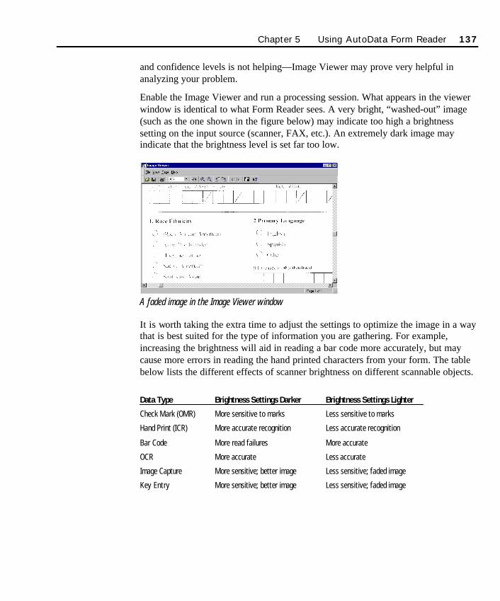
and confidence levels is not helping—Image Viewer may prove very helpful inanalyzing your problem.
Enable the Image Viewer and run a processing session. What appears in the viewerwindow is identical to what Form Reader sees. A very bright, “washed-out” image(such as the one shown in the figure below) may indicate too high a brightnesssetting on the input source (scanner, FAX, etc.). An extremely dark image mayindicate that the brightness level is set far too low.
A faded image in the Image Viewer window
It is worth taking the extra time to adjust the settings to optimize the image in a waythat is best suited for the type of information you are gathering. For example,increasing the brightness will aid in reading a bar code more accurately, but maycause more errors in reading the hand printed characters from your form. The tablebelow lists the different effects of scanner brightness on different scannable objects.
Data Type Brightness Settings Darker Brightness Settings Lighter
Check Mark (OMR) More sensitive to marks Less sensitive to marks
Hand Print (ICR) More accurate recognition Less accurate recognition
Bar Code More read failures More accurate
OCR More accurate Less accurate
Image Capture More sensitive; better image Less sensitive; faded image
Key Entry More sensitive; better image Less sensitive; faded image
Chapter 5 Using AutoData Form Reader 137
SO Chapter 5 Final.qxd 3/21/00 6:26 PM Page 137

138 Chapter 5 Using AutoData Form Reader
SO Chapter 5 Final.qxd 3/21/00 6:26 PM Page 138

139
Chapter 6Using AutoData Data Mapper
In Chapter 5, you learned in detail how AutoData Form Reader reads and processeseach scannable object on a form, and then places the information directly in a targetdatabase or spreadsheet. Knowing where each form’s data elements are placed is theprimary function of the Map file. Form Reader depends on the Map file to direct thedata flow, so it can process forms as efficiently as possible. In this chapter, you willlearn how to create the Map file either automatically or manually using AutoDataData Mapper. The method you select depends on your organization’s specific needs.
Whether the target source is an Access database, an Excel spreadsheet, or an ODBCdata source, Data Mapper can map data to one table or more than one table within adatabase. This feature is very important when working with relational databases thatrely on linked duplicate fields.
This chapter describes how to use Scannable Office’s Data Mapper module tomanage scannable data so it is automatically placed in a database or spreadsheetimmediately after being scanned and processed by the Form Reader module.
The first part, Getting Started, describes how to launch Data Mapper and discussesthe different toolbar and menu features. It also explains the different components ofthe Data Mapper window.
The second part, Creating the Map File: Understanding the Relationship Between aForm and its Database, describes how a Map file tracks the relationship betweenthe Form file and the target database that stores the form’s data. It also describeshow to map data to a new or existing database automatically with the Automapfeature, or manually. The section also presents an overview of how a DatabaseWizard creates a new database to store scanned data.
The third part, Management Tools, describes the role of the Association Manager inkeeping track of the scannable forms library.
SO Chapter 6 Final.qxd 3/21/00 6:27 PM Page 139
140 Chapter 6 Using AutoData Data Mapper
Starting Out
Launching Data Mapper and Viewing FilesThere are two methods of launching the Data Mapper software. A double-click onthe shortcut icon launches the software from the desktop. This method opens theData Mapper module.
The second method accesses Data Mapper through the Form Reader module.Manually launch Data Mapper from the Tools menu.
Ø To launch Data Mapper from the desktop or the Start menu:
1. During installation, Scannable Office places four shortcut icons on yourdesktop. To start Data Mapper, double-click on the icon shown below (or clickStart, point to Programs, then point to the AutoData Scannable Office group,then choose Data Mapper).
Data Mapper shortcut icon
2. The Data Mapper split window appears on screen. The most recently openedForm file and database file will populate the Data Mapper window views.
The Data Mapper ToolbarThe Data Mapper toolbar is attached beneath the drop-down menu bar. If you preferto work with a floating toolbar, double-click on the left margin of the Data Mappertoolbar to display the toolbar over your form. Double-clicking in the title bar at thetop of the toolbar returns it to its default location. You can also reattach the toolbarby dragging it to the top of the window. It will snap into place.
The buttons on the toolbar are, from left to right:
n New: Click this button to select a Form (.FRM) file (or choose New from theFile menu, or press CTRL+N). Once the fields from this file are mapped to adatabase, a new Map file is created.
n Open: Click this button to open an existing Map (.MAP) file (or choose Openfrom the File menu, or press CTRL+O).
SO Chapter 6 Final.qxd 3/21/00 6:27 PM Page 140
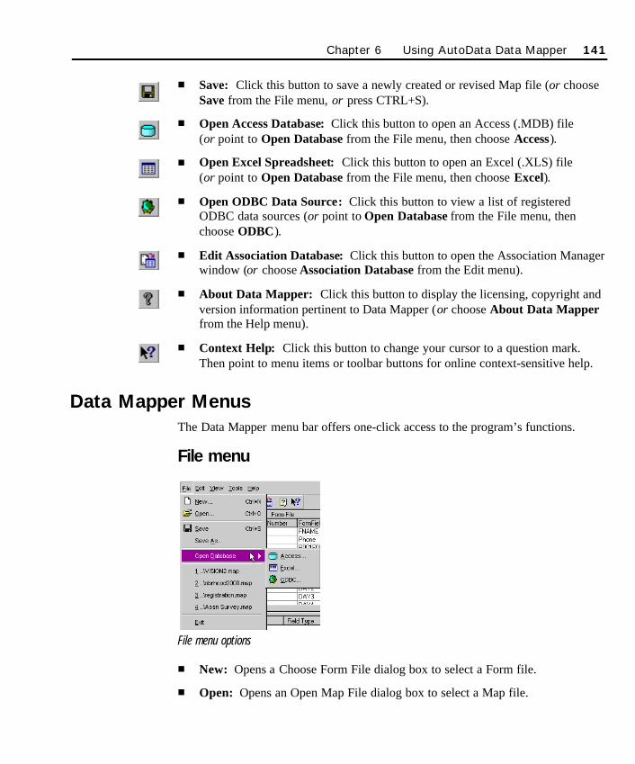
n Save: Click this button to save a newly created or revised Map file (or chooseSave from the File menu, or press CTRL+S).
n Open Access Database: Click this button to open an Access (.MDB) file (or point to Open Database from the File menu, then choose Access).
n Open Excel Spreadsheet: Click this button to open an Excel (.XLS) file (or point to Open Database from the File menu, then choose Excel).
n Open ODBC Data Source: Click this button to view a list of registeredODBC data sources (or point to Open Database from the File menu, thenchoose ODBC).
n Edit Association Database: Click this button to open the Association Managerwindow (or choose Association Database from the Edit menu).
n About Data Mapper: Click this button to display the licensing, copyright andversion information pertinent to Data Mapper (or choose About Data Mapperfrom the Help menu).
n Context Help: Click this button to change your cursor to a question mark.Then point to menu items or toolbar buttons for online context-sensitive help.
Data Mapper MenusThe Data Mapper menu bar offers one-click access to the program’s functions.
File menu
File menu options
n New: Opens a Choose Form File dialog box to select a Form file.
n Open: Opens an Open Map File dialog box to select a Map file.
Chapter 6 Using AutoData Data Mapper 141
SO Chapter 6 Final.qxd 3/21/00 6:27 PM Page 141
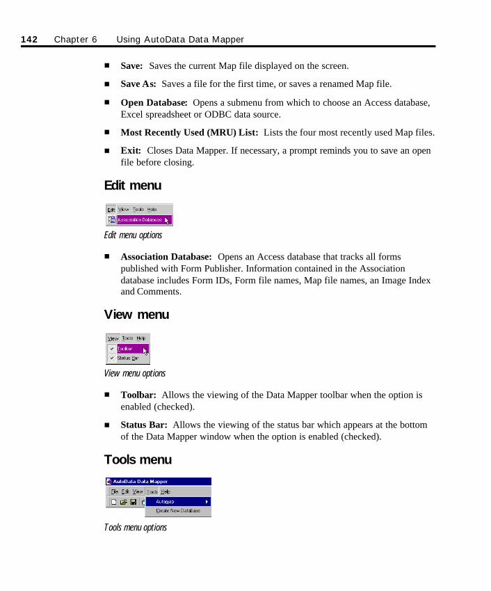
n Save: Saves the current Map file displayed on the screen.
n Save As: Saves a file for the first time, or saves a renamed Map file.
n Open Database: Opens a submenu from which to choose an Access database,Excel spreadsheet or ODBC data source.
n Most Recently Used (MRU) List: Lists the four most recently used Map files.
n Exit: Closes Data Mapper. If necessary, a prompt reminds you to save an openfile before closing.
Edit menu
Edit menu options
n Association Database: Opens an Access database that tracks all formspublished with Form Publisher. Information contained in the Associationdatabase includes Form IDs, Form file names, Map file names, an Image Indexand Comments.
View menu
View menu options
n Toolbar: Allows the viewing of the Data Mapper toolbar when the option isenabled (checked).
n Status Bar: Allows the viewing of the status bar which appears at the bottomof the Data Mapper window when the option is enabled (checked).
Tools menu
Tools menu options
142 Chapter 6 Using AutoData Data Mapper
SO Chapter 6 Final.qxd 3/21/00 6:27 PM Page 142
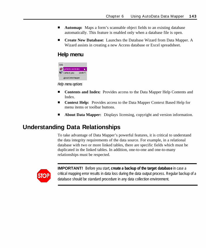
n Automap: Maps a form’s scannable object fields to an existing databaseautomatically. This feature is enabled only when a database file is open.
n Create New Database: Launches the Database Wizard from Data Mapper. AWizard assists in creating a new Access database or Excel spreadsheet.
Help menu
Help menu options
n Contents and Index: Provides access to the Data Mapper Help Contents andIndex.
n Context Help: Provides access to the Data Mapper Context Based Help formenu items or toolbar buttons.
n About Data Mapper: Displays licensing, copyright and version information.
Understanding Data RelationshipsTo take advantage of Data Mapper’s powerful features, it is critical to understandthe data integrity requirements of the data source. For example, in a relationaldatabase with two or more linked tables, there are specific fields which must beduplicated in the linked tables. In addition, one-to-one and one-to-manyrelationships must be respected.
IMPORTANT! Before you start, create a backup of the target database in case acritical mapping error results in data loss during the data output process. Regular backup of adatabase should be standard procedure in any data collection environment.
Chapter 6 Using AutoData Data Mapper 143
SO Chapter 6 Final.qxd 3/21/00 6:27 PM Page 143
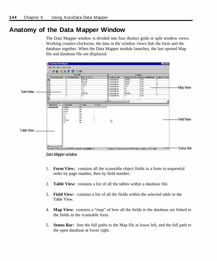
Anatomy of the Data Mapper WindowThe Data Mapper window is divided into four distinct grids or split window views.Working counter-clockwise, the data in the window views link the form and thedatabase together. When the Data Mapper module launches, the last opened Mapfile and database file are displayed.
Data Mapper window
1. Form View: contains all the scannable object fields in a form in sequentialorder by page number, then by field number.
2. Table View: contains a list of all the tables within a database file.
3. Field View: contains a list of all the fields within the selected table in theTable View.
4. Map View: contains a “map” of how all the fields in the database are linked tothe fields in the scannable form.
5. Status Bar: lists the full paths to the Map file at lower left, and the full path tothe open database at lower right.
144 Chapter 6 Using AutoData Data Mapper
Form View
Table View
Map View
Field View
Status Bar
SO Chapter 6 Final.qxd 3/21/00 6:27 PM Page 144
Creating the Map File: Understanding theRelationship Between a Form and Its Database
Data Mapper links scannable objects on a form with their corresponding fields in anexisting Access database, Excel spreadsheet or ODBC data source. Establishing theMap file information involves these steps:
n Step 1: Selecting the Form file.
n Step 2: Selecting or creating the database to store the form’s data. If adatabase does not already exist, use Data Mapper to create one.
n Step 3: Matching the form’s fields with the database fields. Data Mappercan perform this step automatically with Automap.
n Step 4: Saving the new Map file and exiting Data Mapper.
Step 1: Selecting the Form FileIn order to link the form to the correct database through a Map file, a FormDefinition file (.FRM) must exist. Think of the Form file as a template which, whenoverlaid on a scannable form, identifies the exact location and type of eachscannable object on the form. When Form Publisher is the design tool of choice, aForm file is created after the form passes the critical checkpoints and is successfullyPublished. If a third-party program (e.g., PageMaker) is used, the scannable objectsmust be manually defined using Template Maker. This definition process creates theForm file. AutoData PRO forms which have already been defined using AutoDataFORM are compatible with Scannable Office.
Ø To open a Form file prior to creating a Map file:
1. Click on the Create a New Map File icon (or choose New from the File menu).The Choose a Form File dialog box will be displayed. The Form file created byForm Publisher is typically located in the same directory as the Word .DOC filecreated by Form Publisher.
Form files are createdwith Form Publisher,Template Maker orAutoData FORM.
Chapter 6 Using AutoData Data Mapper 145
SO Chapter 6 Final.qxd 3/21/00 6:27 PM Page 145
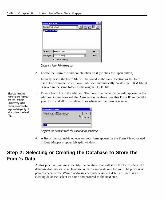
Choose a Form File dialog box
2. Locate the Form file and double-click on it (or click the Open button).
In many cases, the Form file will be found in the same location as the formitself. For example, when Form Publisher automatically creates the .FRM file, itis saved in the same folder as the original .DOC file.
3. Enter a Form ID in the edit box. The Form file name, by default, appears in theedit box. Going forward, the Association database uses this Form ID to identifyyour form and all of its related files whenever the form is scanned.
Register the Form ID with the Association database
4. A list of the scannable objects on your form appears in the Form View, locatedin Data Mapper’s upper left split window.
Step 2: Selecting or Creating the Database to Store theForm’s Data
At this juncture, you must identify the database that will store the form’s data. If adatabase does not exist, a Database Wizard can create one for you. The process ispainless because the Wizard addresses behind-the-scenes details. If there is anexisting database, select its name and proceed to the next step.
Tip: Use the samename for the Form IDand the Form file.Consistency in filenames preserves thelogic and simplicity ofall your form’s relatedfiles.
146 Chapter 6 Using AutoData Data Mapper
SO Chapter 6 Final.qxd 3/21/00 6:27 PM Page 146
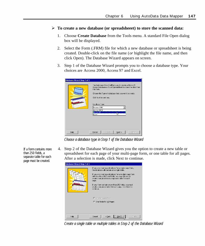
Chapter 6 Using AutoData Data Mapper 147
Ø To create a new database (or spreadsheeet) to store the scanned data:
1. Choose Create Database from the Tools menu. A standard File Open dialogbox will be displayed.
2. Select the Form (.FRM) file for which a new database or spreadsheet is beingcreated. Double-click on the file name (or highlight the file name, and thenclick Open). The Database Wizard appears on screen.
3. Step 1 of the Database Wizard prompts you to choose a database type. Yourchoices are Access 2000, Access 97 and Excel.
Choose a database type in Step 1 of the Database Wizard
4. Step 2 of the Database Wizard gives you the option to create a new table orspreadsheet for each page of your multi-page form, or one table for all pages.After a selection is made, click Next to continue.
Create a single table or multiple tables in Step 2 of the Database Wizard
If a form contains morethan 250 fields, aseparate table for eachpage must be created.
SO Chapter 6 Final.qxd 3/21/00 6:27 PM Page 147
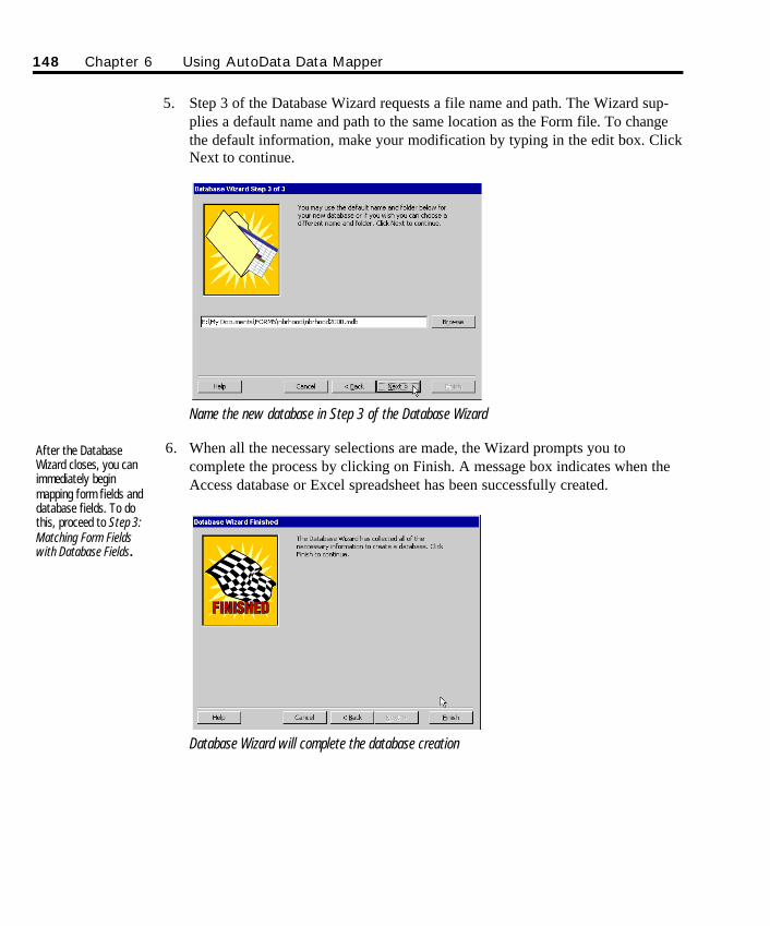
5. Step 3 of the Database Wizard requests a file name and path. The Wizard sup-plies a default name and path to the same location as the Form file. To changethe default information, make your modification by typing in the edit box. ClickNext to continue.
Name the new database in Step 3 of the Database Wizard
6. When all the necessary selections are made, the Wizard prompts you tocomplete the process by clicking on Finish. A message box indicates when theAccess database or Excel spreadsheet has been successfully created.
Database Wizard will complete the database creation
After the DatabaseWizard closes, you canimmediately beginmapping form fields anddatabase fields. To dothis, proceed to Step 3:Matching Form Fieldswith Database Fields.
148 Chapter 6 Using AutoData Data Mapper
SO Chapter 6 Final.qxd 3/21/00 6:27 PM Page 148
Ø To identify an existing database (or spreadsheet) to store the scanned data:
1. Click the appropriate toolbar button: Open Access Database, Open ExcelSpreadsheet or Open ODBC Data Source (or point to Open Database from theFile menu, then choose either Access, Excel or ODBC from the submenu). Thestandard File Open dialog box will be displayed.
2. Browse for the appropriate database (or spreadsheet) that contains the scanneddata. Verify that the name and path are correct. Select the file and click OK.
3. The selected database appears in the Table View, located in Data Mapper’slower left split window. The individual fields within the selected database tableappear in the Field View to the right.
Step 3: Matching Form Fields with Database Fields
In order for Scannable Office to operate properly, the software must know theintricacies of how a form’s scannable fields correspond with the fields in the targetdatabase. During the scanning process, Form Reader must know exactly where itshould place the data in the database. The mechanism used to tell Form Readerwhere to place the data is a Map file.
Data Mapper offers two ways to map the fields. The first method uses the Automaproutine to map the form data to the target database. The second method uses amanual mapping procedure. The recommended method is to use the Automapfunction. Only when fields cannot be automatically mapped should the manualmethod be used, or if you have advanced requirements that go beyond the scope ofthe normal Automap function.
If you use the Database Wizard to create a new database, upon completion of thattask, Data Mapper immediately asks you to run the Automap function. This is therecommended course of action.
Preparations leading up to creating a Map file
Regardless of how your form is created, every scannable form must have anaccompanying scannable template, or a .FRM file. Let’s briefly outline the differentscenarios that are possible.
The Map file structureis explained in detail inAppendix D.
Chapter 6 Using AutoData Data Mapper 149
SO Chapter 6 Final.qxd 3/21/00 6:27 PM Page 149
n Form created in Form Publisher; NEW database required. If your form iscreated in Form Publisher, the normal course of action is to Publish the form,administer the form, and then begin scanning the form with Form Reader. Sincethis is a new form, no target database has been specified. Therefore, thesoftware does not know where to place the form’s fields. Form Reader askssome key questions and automatically creates a new database and Map file. TheAutomap function is performed for you, and you can immediately resumescanning.
n Form created outside of Form Publisher, defined in Template Maker;NEW database required. If your form is created with a software programother than Form Publisher, the form’s scannable object types and locations mustbe defined in Template Maker. (This step is not required if you have alreadydefined an existing form with AutoData FORM 4.0 or higher.) The output is aForm (.FRM) file. Similar to the scenario described above, the normal course ofaction is to print and administer the form, and then begin scanning the formwith Form Reader. Since this is a new form, no target database has beenspecified. The exact same process will unfold, whereby Form Reader asks somekey questions and creates a new database. Scanning can resume once theAutomap routine is finished.
n Form created in Form Publisher; map to EXISTING database. If your formis created in Form Publisher, save and Publish the form, then administer it.Before scanning can commence, a Map file must be created. Start the DataMapper module, and use the Automap feature (or manual process) describedbelow to map fields from your form to an existing database. Then beginscanning the form with Form Reader. Since you’ve already created the Map file,Form Reader will not intervene since it knows where to direct the scanned data.Going forward, this form will continue to be recognized by Form Reader.
n Form created outside of Form Publisher, defined in Template Maker; mapto EXISTING database. If your form is created with a software program otherthan Form Publisher, the form’s scannable object types and locations must bedefined in Template Maker. (This step is not required if you have alreadydefined an existing form with AutoData FORM 4.0 or higher.) The output is aForm (.FRM) file. Print and administer the form. Prior to scanning, a Map filemust be created. Similar to the scenario just described, start the Data Mappermodule and use the Automap feature (or manual process) described below tomap fields from your form to an existing database. Once you’ve completed thisstep, begin scanning forms with Form Reader. Since you’ve already created theMap file, Form Reader will not intervene, and your form will continue to berecognized each time it is scanned by Form Reader.
If your form is mappingto an existingdatabase, use DataMapper to create theMap file. Read thesection below forfurther instructions.
If you are mapping aform to a newdatabase, Form Readerwill walk you throughthe process to create aMap file. In mostcases, you do not haveto use Data Mapper tocreate the Map file.
150 Chapter 6 Using AutoData Data Mapper
SO Chapter 6 Final.qxd 3/21/00 6:27 PM Page 150
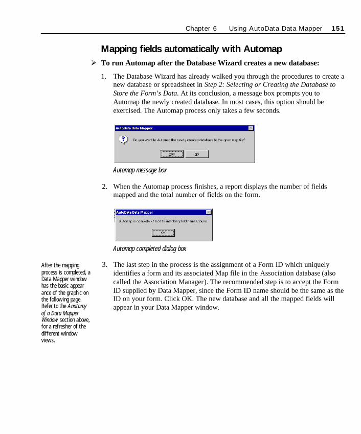
Mapping fields automatically with AutomapØ To run Automap after the Database Wizard creates a new database:
1. The Database Wizard has already walked you through the procedures to create anew database or spreadsheet in Step 2: Selecting or Creating the Database toStore the Form’s Data. At its conclusion, a message box prompts you toAutomap the newly created database. In most cases, this option should beexercised. The Automap process only takes a few seconds.
Automap message box
2. When the Automap process finishes, a report displays the number of fieldsmapped and the total number of fields on the form.
Automap completed dialog box
3. The last step in the process is the assignment of a Form ID which uniquelyidentifies a form and its associated Map file in the Association database (alsocalled the Association Manager). The recommended step is to accept the FormID supplied by Data Mapper, since the Form ID name should be the same as theID on your form. Click OK. The new database and all the mapped fields willappear in your Data Mapper window.
After the mappingprocess is completed, aData Mapper windowhas the basic appear-ance of the graphic onthe following page.Refer to the Anatomyof a Data MapperWindow section above,for a refresher of thedifferent windowviews.
Chapter 6 Using AutoData Data Mapper 151
SO Chapter 6 Final.qxd 3/21/00 6:27 PM Page 151
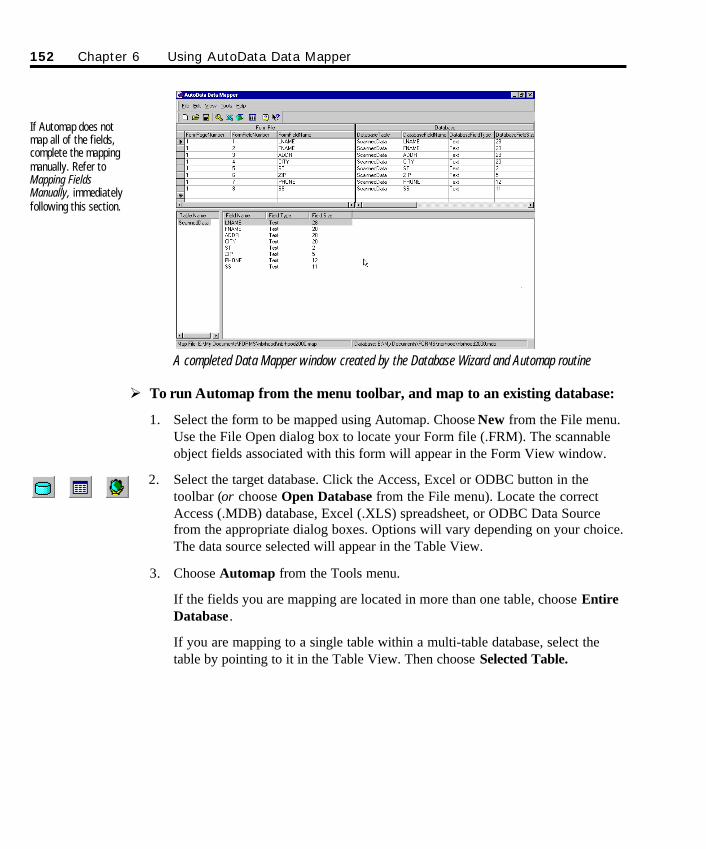
A completed Data Mapper window created by the Database Wizard and Automap routine
Ø To run Automap from the menu toolbar, and map to an existing database:
1. Select the form to be mapped using Automap. Choose New from the File menu.Use the File Open dialog box to locate your Form file (.FRM). The scannableobject fields associated with this form will appear in the Form View window.
2. Select the target database. Click the Access, Excel or ODBC button in thetoolbar (or choose Open Database from the File menu). Locate the correctAccess (.MDB) database, Excel (.XLS) spreadsheet, or ODBC Data Sourcefrom the appropriate dialog boxes. Options will vary depending on your choice.The data source selected will appear in the Table View.
3. Choose Automap from the Tools menu.
If the fields you are mapping are located in more than one table, choose EntireDatabase.
If you are mapping to a single table within a multi-table database, select thetable by pointing to it in the Table View. Then choose Selected Table.
152 Chapter 6 Using AutoData Data Mapper
If Automap does notmap all of the fields,complete the mappingmanually. Refer toMapping FieldsManually, immediatelyfollowing this section.
SO Chapter 6 Final.qxd 3/21/00 6:27 PM Page 152
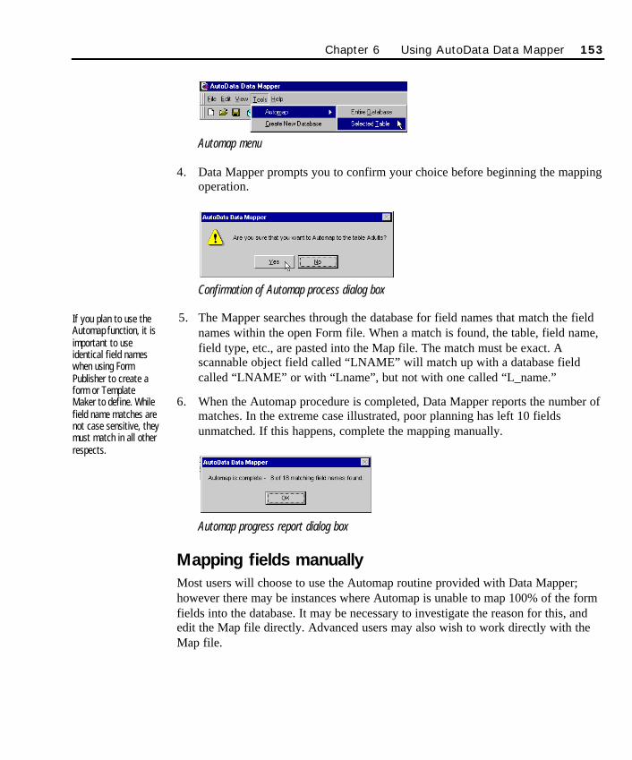
Automap menu
4. Data Mapper prompts you to confirm your choice before beginning the mappingoperation.
Confirmation of Automap process dialog box
5. The Mapper searches through the database for field names that match the fieldnames within the open Form file. When a match is found, the table, field name,field type, etc., are pasted into the Map file. The match must be exact. Ascannable object field called “LNAME” will match up with a database fieldcalled “LNAME” or with “Lname”, but not with one called “L_name.”
6. When the Automap procedure is completed, Data Mapper reports the number ofmatches. In the extreme case illustrated, poor planning has left 10 fieldsunmatched. If this happens, complete the mapping manually.
Automap progress report dialog box
Mapping fields manuallyMost users will choose to use the Automap routine provided with Data Mapper;however there may be instances where Automap is unable to map 100% of the formfields into the database. It may be necessary to investigate the reason for this, andedit the Map file directly. Advanced users may also wish to work directly with theMap file.
If you plan to use theAutomap function, it isimportant to useidentical field nameswhen using FormPublisher to create aform or TemplateMaker to define. Whilefield name matches arenot case sensitive, theymust match in all otherrespects.
Chapter 6 Using AutoData Data Mapper 153
SO Chapter 6 Final.qxd 3/21/00 6:27 PM Page 153
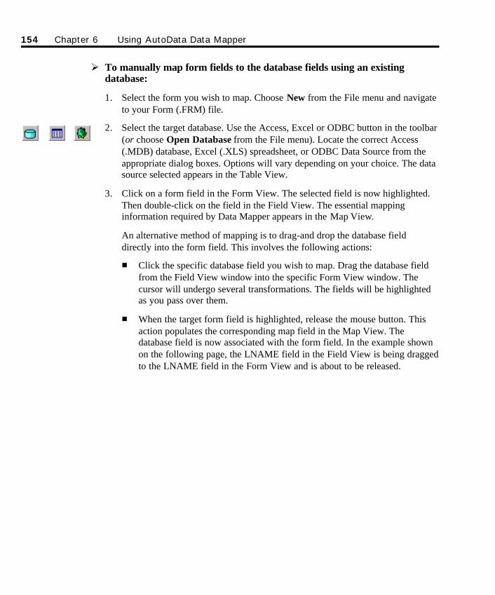
Ø To manually map form fields to the database fields using an existingdatabase:
1. Select the form you wish to map. Choose New from the File menu and navigateto your Form (.FRM) file.
2. Select the target database. Use the Access, Excel or ODBC button in the toolbar(or choose Open Database from the File menu). Locate the correct Access(.MDB) database, Excel (.XLS) spreadsheet, or ODBC Data Source from theappropriate dialog boxes. Options will vary depending on your choice. The datasource selected appears in the Table View.
3. Click on a form field in the Form View. The selected field is now highlighted.Then double-click on the field in the Field View. The essential mappinginformation required by Data Mapper appears in the Map View.
An alternative method of mapping is to drag-and drop the database fielddirectly into the form field. This involves the following actions:
n Click the specific database field you wish to map. Drag the database fieldfrom the Field View window into the specific Form View window. Thecursor will undergo several transformations. The fields will be highlightedas you pass over them.
n When the target form field is highlighted, release the mouse button. Thisaction populates the corresponding map field in the Map View. Thedatabase field is now associated with the form field. In the example shownon the following page, the LNAME field in the Field View is being draggedto the LNAME field in the Form View and is about to be released.
154 Chapter 6 Using AutoData Data Mapper
SO Chapter 6 Final.qxd 3/21/00 6:27 PM Page 154
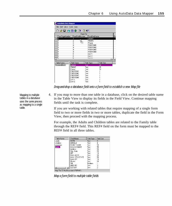
Chapter 6 Using AutoData Data Mapper 155
Drag-and-drop a database field onto a form field to establish a new Map file
4. If you map to more than one table in a database, click on the desired table namein the Table View to display its fields in the Field View. Continue mappingfields until the task is complete.
If you are working with related tables that require mapping of a single formfield to two or more fields in two or more tables, duplicate the field in the FormView, then proceed with the mapping process.
For example, the Adults and Children tables are related to the Family tablethrough the REF# field. This REF# field on the form must be mapped to theREF# field in all three tables.
Map a form field to multiple table fields
Mapping to multipletables in a databaseuses the same processas mapping to a singletable.
SO Chapter 6 Final.qxd 3/21/00 6:27 PM Page 155
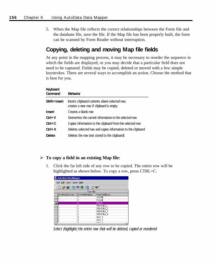
5. When the Map file reflects the correct relationships between the Form file andthe database file, save the file. If the Map file has been properly built, the formcan be scanned by Form Reader without interruption.
Copying, deleting and moving Map file fieldsAt any point in the mapping process, it may be necessary to reorder the sequence inwhich the fields are displayed, or you may decide that a particular field does notneed to be captured. Fields may be copied, deleted or moved with a few simplekeystrokes. There are several ways to accomplish an action. Choose the method thatis best for you.
KeyboardCommand Behavior
Shift+Insert Inserts clipboard contents above selected row;creates a new row if clipboard is empty
Insert Creates a blank row
Ctrl+V Overwrites the current information in the selected row
Ctrl+C Copies information to the clipboard from the selected row
Ctrl+X Deletes selected row and copies information to the clipboard
Delete Deletes the row (not stored to the clipboard)
Ø To copy a field in an existing Map file:
1. Click the far left side of any row to be copied. The entire row will behighlighted as shown below. To copy a row, press CTRL+C.
Select (highlight) the entire row that will be deleted, copied or reordered
156 Chapter 6 Using AutoData Data Mapper
SO Chapter 6 Final.qxd 3/21/00 6:27 PM Page 156
2. To insert the last copied row in a new location, click to highlight the rowimmediately above the point the copied row will be placed.
3. Press the Shift+Insert keys. The newly inserted row will appear above thehighlighted row, and will not overwrite the selected row. In the example shownabove, the new row will appear between the FNAME and Phone fields.
Ø To overwrite a field with another field in an existing Map file:
1. Click the far left side of any row that you wish to copy. The entire row will behighlighted. To copy a row, press CTRL+C.
2. To select the row you wish to overwrite, highlight the entire row. To paste thecopied row into the row you wish to overwrite, press CTRL+V. This overwritesany information contained in the row.
Ø To delete a field in an existing Map file:
1. Click the far left side of any row to be deleted. The entire row will behighlighted.
2. To delete the row, press the Delete key (or press CTRL+X).
Ø To move a field in an existing Map file:
1. Click the far left side of any row to be moved. The entire row will behighlighted.
2. To move the entire row, delete (cut) the row by pressing the Delete key (or press CTRL+X).
3. To insert the last cut row in a new location, click to highlight the rowimmediately above the point the copied row will be placed.
4. Press the Shift+Insert keys. The newly inserted row will appear above thehighlighted row.
Ø To add a blank row in an existing Map file:
1. To insert a blank row, highlight the row immediately below the point theinserted row will be placed.
2. Press the Insert key. The new blank row will appear above the highlighted row.
Chapter 6 Using AutoData Data Mapper 157
SO Chapter 6 Final.qxd 3/21/00 6:27 PM Page 157
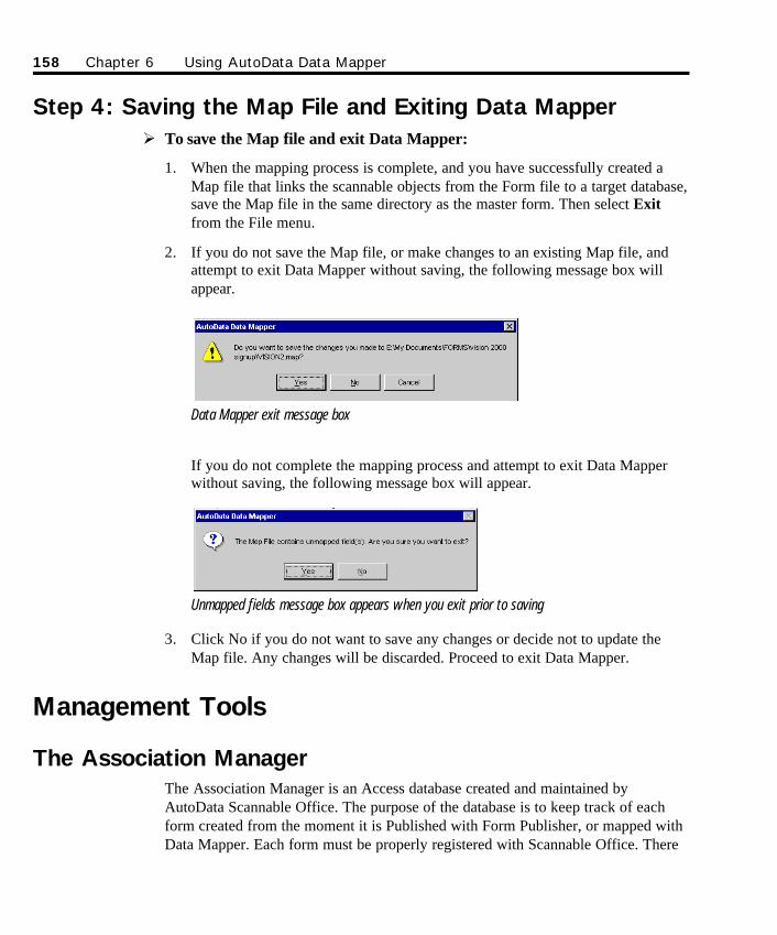
Step 4: Saving the Map File and Exiting Data MapperØ To save the Map file and exit Data Mapper:
1. When the mapping process is complete, and you have successfully created aMap file that links the scannable objects from the Form file to a target database,save the Map file in the same directory as the master form. Then select Exitfrom the File menu.
2. If you do not save the Map file, or make changes to an existing Map file, andattempt to exit Data Mapper without saving, the following message box willappear.
Data Mapper exit message box
If you do not complete the mapping process and attempt to exit Data Mapperwithout saving, the following message box will appear.
Unmapped fields message box appears when you exit prior to saving
3. Click No if you do not want to save any changes or decide not to update theMap file. Any changes will be discarded. Proceed to exit Data Mapper.
Management Tools
The Association Manager The Association Manager is an Access database created and maintained byAutoData Scannable Office. The purpose of the database is to keep track of eachform created from the moment it is Published with Form Publisher, or mapped withData Mapper. Each form must be properly registered with Scannable Office. There
158 Chapter 6 Using AutoData Data Mapper
SO Chapter 6 Final.qxd 3/21/00 6:27 PM Page 158
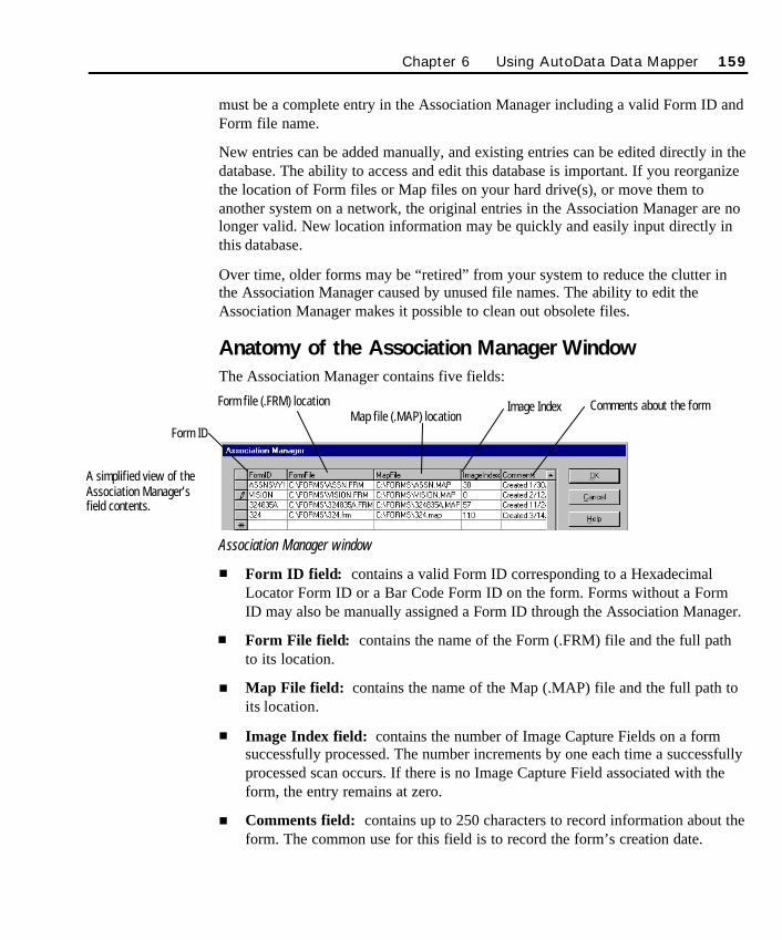
must be a complete entry in the Association Manager including a valid Form ID andForm file name.
New entries can be added manually, and existing entries can be edited directly in thedatabase. The ability to access and edit this database is important. If you reorganizethe location of Form files or Map files on your hard drive(s), or move them toanother system on a network, the original entries in the Association Manager are nolonger valid. New location information may be quickly and easily input directly inthis database.
Over time, older forms may be “retired” from your system to reduce the clutter inthe Association Manager caused by unused file names. The ability to edit theAssociation Manager makes it possible to clean out obsolete files.
Anatomy of the Association Manager WindowThe Association Manager contains five fields:
Association Manager window
n Form ID field: contains a valid Form ID corresponding to a HexadecimalLocator Form ID or a Bar Code Form ID on the form. Forms without a FormID may also be manually assigned a Form ID through the Association Manager.
n Form File field: contains the name of the Form (.FRM) file and the full pathto its location.
n Map File field: contains the name of the Map (.MAP) file and the full path toits location.
n Image Index field: contains the number of Image Capture Fields on a formsuccessfully processed. The number increments by one each time a successfullyprocessed scan occurs. If there is no Image Capture Field associated with theform, the entry remains at zero.
n Comments field: contains up to 250 characters to record information about theform. The common use for this field is to record the form’s creation date.
Chapter 6 Using AutoData Data Mapper 159
Form ID
Form file (.FRM) locationMap file (.MAP) location
Image Index Comments about the form
A simplified view of theAssociation Manager’sfield contents.
SO Chapter 6 Final.qxd 3/21/00 6:27 PM Page 159
As a reminder, Form IDs have different character limits depending on the type ofForm ID used. Refer to the following chart for reference.
Form ID Type Character Limits Comments
Bar code 8 - base 8 in base name, 1 hyphen, and 2 characters reserved for page number 11 - total (i.e., satisfy-14, where base name=satisfy, page number=14)
Hexadecimal 3 ID embedded in the 3 Locators on a form using hexadecimal charactersLocator
No Printed ID 12 For use when neither a barcode or Hex Locator Form ID is used.Name the Form ID in the Association Manager.
Modifying the Association Manager fieldsØ To open the Association Manager:
1. Data Mapper offers one-click access to the Association Manager. To open theAssociation Manager, click the Edit Associations button in the toolbar (orchoose Association Database from the Edit menu).
2. The Association Manager launches on screen and displays information in thefive fields discussed previously.
Ø To modify any record in the Association Manager:
1. Place the cursor in any of the database records, double-click to highlight theentire record, and overwrite its contents by typing the change(s). If you prefer,place the cursor in the appropriate record and type to insert changes.
2. Use this method to modify any Form ID name, Form file name or path, Mapfile name or path; to increment or decrement the Image index, and to modifyany comments.
Ø To modify or add Form files in the Association Manager:
1. To insert or modify a Form file name in the Association Manager, double-clickon the Form file field.
2. When the Choose a Form File dialog box opens, locate the Form file (.FRM)you wish to associate with the form. Click OK. The complete file path isinserted into the Form file field in the Association Manager.
160 Chapter 6 Using AutoData Data Mapper
SO Chapter 6 Final.qxd 3/21/00 6:27 PM Page 160
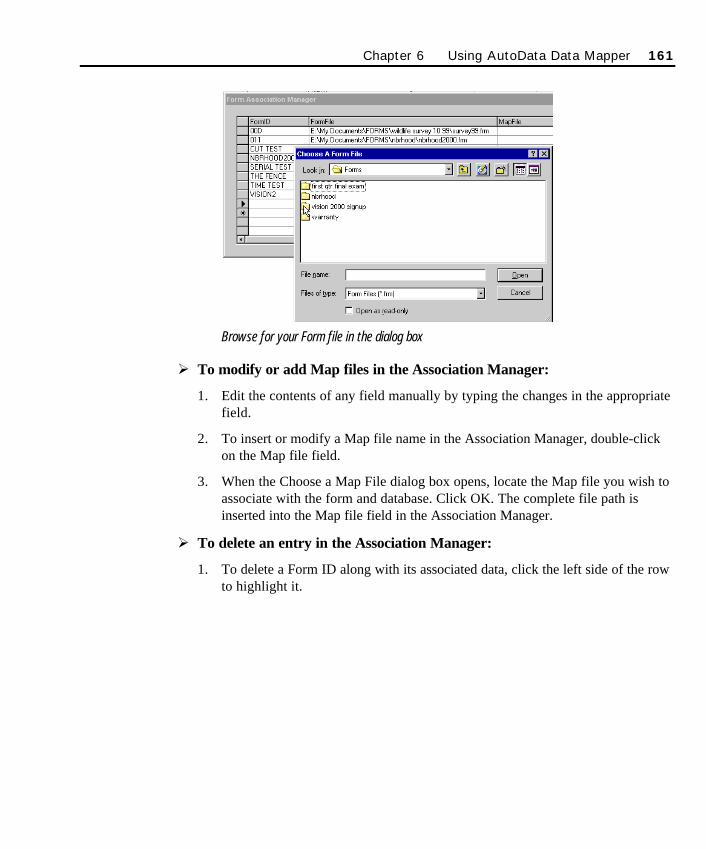
Browse for your Form file in the dialog box
Ø To modify or add Map files in the Association Manager:
1. Edit the contents of any field manually by typing the changes in the appropriatefield.
2. To insert or modify a Map file name in the Association Manager, double-clickon the Map file field.
3. When the Choose a Map File dialog box opens, locate the Map file you wish toassociate with the form and database. Click OK. The complete file path isinserted into the Map file field in the Association Manager.
Ø To delete an entry in the Association Manager:
1. To delete a Form ID along with its associated data, click the left side of the rowto highlight it.
Chapter 6 Using AutoData Data Mapper 161
SO Chapter 6 Final.qxd 3/21/00 6:27 PM Page 161
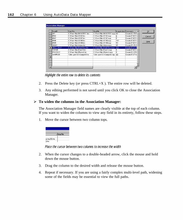
Highlight the entire row to delete its contents
2. Press the Delete key (or press CTRL+X ). The entire row will be deleted.
3. Any editing performed is not saved until you click OK to close the AssociationManager.
Ø To widen the columns in the Association Manager:
The Association Manager field names are clearly visible at the top of each column.If you want to widen the columns to view any field in its entirety, follow these steps.
1. Move the cursor between two column tops.
Place the cursor between two columns to increase the width
2. When the cursor changes to a double-headed arrow, click the mouse and holddown the mouse button.
3. Drag the column to the desired width and release the mouse button.
4. Repeat if necessary. If you are using a fairly complex multi-level path, wideningsome of the fields may be essential to view the full paths.
162 Chapter 6 Using AutoData Data Mapper
SO Chapter 6 Final.qxd 3/21/00 6:27 PM Page 162

Ø To exit the Association Manager:
1. When you are finished with the Association Manager, click OK to close. Anychanges you make are automatically saved.
2. Click Cancel to close the Association Manager without saving changes.
Chapter 6 Using AutoData Data Mapper 163
SO Chapter 6 Final.qxd 3/21/00 6:27 PM Page 163

164 Chapter 6 Using AutoData Data Mapper
SO Chapter 6 Final.qxd 3/21/00 6:27 PM Page 164

165
Chapter 7Advanced Topics
Batch Scanning and ProcessingWhen you choose to work in Batch mode, Form Reader treats the scanning andprocess/verification steps as two separate activities. Batch mode enables you to scanforms in one setting, and then process and verify those forms either immediatelyfollowing scanning, or at some later time. Batch mode processing can be performedon either standalone workstations, or from multiple workstations on a network.
Batch scanningØ To scan forms in batch mode:
1. Launch the Form Reader module.
2. To set the proper options applicable to batch scanning in the Form Readersetup, choose Options from the Tools menu. Then select the Process tab. Thistab contains various processing options. The Batch Mode section contains asingle check box to specify how to handle images after processing. When theDelete Images After Processing option is checked or turned on (the default),all Image files are deleted after they are processed, freeing up valuable diskdrive space.
As a rule of thumb, the recommended setting is to select the Delete Imagesoption if your input source is an ISIS or TWAIN scanner. The scanned formsare likely to exist in a hard copy format which can be saved and retrieved ifnecessary.
SO Chapter 7 Final.qxd 3/21/00 6:28 PM Page 165
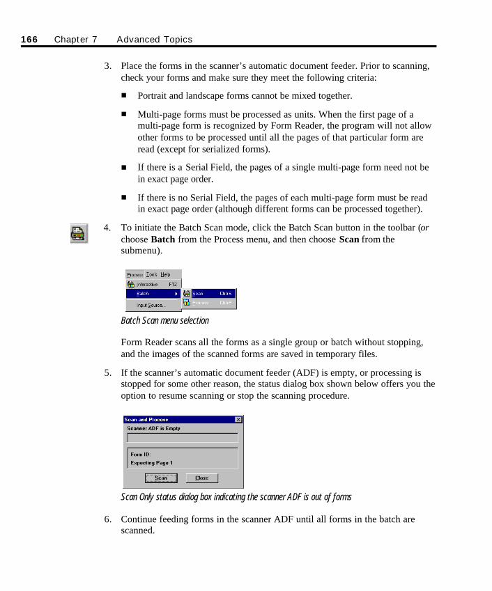
166 Chapter 7 Advanced Topics
3. Place the forms in the scanner’s automatic document feeder. Prior to scanning,check your forms and make sure they meet the following criteria:
n Portrait and landscape forms cannot be mixed together.
n Multi-page forms must be processed as units. When the first page of amulti-page form is recognized by Form Reader, the program will not allowother forms to be processed until all the pages of that particular form areread (except for serialized forms).
n If there is a Serial Field, the pages of a single multi-page form need not bein exact page order.
n If there is no Serial Field, the pages of each multi-page form must be readin exact page order (although different forms can be processed together).
4. To initiate the Batch Scan mode, click the Batch Scan button in the toolbar (orchoose Batch from the Process menu, and then choose Scan from thesubmenu).
Batch Scan menu selection
Form Reader scans all the forms as a single group or batch without stopping,and the images of the scanned forms are saved in temporary files.
5. If the scanner’s automatic document feeder (ADF) is empty, or processing isstopped for some other reason, the status dialog box shown below offers you theoption to resume scanning or stop the scanning procedure.
Scan Only status dialog box indicating the scanner ADF is out of forms
6. Continue feeding forms in the scanner ADF until all forms in the batch arescanned.
SO Chapter 7 Final.qxd 3/21/00 6:28 PM Page 166
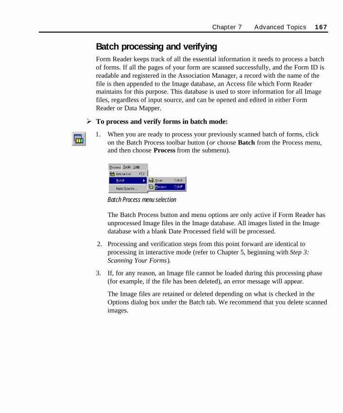
Batch processing and verifyingForm Reader keeps track of all the essential information it needs to process a batchof forms. If all the pages of your form are scanned successfully, and the Form ID isreadable and registered in the Association Manager, a record with the name of thefile is then appended to the Image database, an Access file which Form Readermaintains for this purpose. This database is used to store information for all Imagefiles, regardless of input source, and can be opened and edited in either FormReader or Data Mapper.
Ø To process and verify forms in batch mode:
1. When you are ready to process your previously scanned batch of forms, clickon the Batch Process toolbar button (or choose Batch from the Process menu,and then choose Process from the submenu).
Batch Process menu selection
The Batch Process button and menu options are only active if Form Reader hasunprocessed Image files in the Image database. All images listed in the Imagedatabase with a blank Date Processed field will be processed.
2. Processing and verification steps from this point forward are identical toprocessing in interactive mode (refer to Chapter 5, beginning with Step 3:Scanning Your Forms).
3. If, for any reason, an Image file cannot be loaded during this processing phase(for example, if the file has been deleted), an error message will appear.
The Image files are retained or deleted depending on what is checked in theOptions dialog box under the Batch tab. We recommend that you delete scannedimages.
Chapter 7 Advanced Topics 167
SO Chapter 7 Final.qxd 3/21/00 6:28 PM Page 167
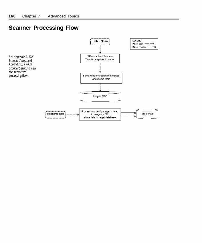
Scanner Processing Flow
168 Chapter 7 Advanced Topics
See Appendix B, ISISScanner Setup, andAppendix C, TWAINScanner Setup, to viewthe interactiveprocessing flow.
SO Chapter 7 Final.qxd 3/21/00 6:28 PM Page 168
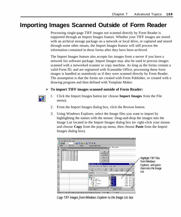
Importing Images Scanned Outside of Form ReaderProcessing single-page TIFF images not scanned directly by Form Reader issupported through an Import Images feature. Whether your TIFF images are storedwith an archival storage package on a network or local drive, or captured and storedthrough some other means, the Import Images feature will still process theinformation contained in these forms after they have been archived.
The Import Images feature also accepts fax images from a server if you have anetwork fax software package. Import Images may also be used to process imagesscanned with a networked scanner or copy machine. As long as the forms contain avalid Form ID, and are registered with Scannable Office, processing these formimages is handled as seamlessly as if they were scanned directly by Form Reader.The assumption is that the forms are created with Form Publisher, or created with adrawing program and then defined with Template Maker.
Ø To import TIFF images scanned outside of Form Reader:
1. Click the Import Images button (or choose Import Images from the Filemenu).
2. From the Import Images dialog box, click the Browse button.
3. Using Windows Explorer, select the Image files you want to import byhighlighting the names with the mouse. Drag-and-drop the images into theImage List located in the Import Images dialog box (or right-click your mouseand choose Copy from the pop-up menu, then choose Paste from the ImportImages dialog box).
Copy TIFF images from Windows Explorer to the Image List box
Chapter 7 Advanced Topics 169
Highlight TIFF filesfrom WindowsExplorer, and pastethem into the ImageList
SO Chapter 7 Final.qxd 3/21/00 6:28 PM Page 169
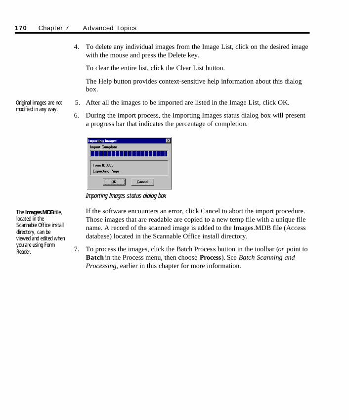
4. To delete any individual images from the Image List, click on the desired imagewith the mouse and press the Delete key.
To clear the entire list, click the Clear List button.
The Help button provides context-sensitive help information about this dialogbox.
5. After all the images to be imported are listed in the Image List, click OK.
6. During the import process, the Importing Images status dialog box will presenta progress bar that indicates the percentage of completion.
Importing Images status dialog box
If the software encounters an error, click Cancel to abort the import procedure.Those images that are readable are copied to a new temp file with a unique filename. A record of the scanned image is added to the Images.MDB file (Accessdatabase) located in the Scannable Office install directory.
7. To process the images, click the Batch Process button in the toolbar (or point toBatch in the Process menu, then choose Process). See Batch Scanning andProcessing, earlier in this chapter for more information.
The Images.MDB file,located in theScannable Office installdirectory, can beviewed and edited whenyou are using FormReader.
Original images are notmodified in any way.
170 Chapter 7 Advanced Topics
SO Chapter 7 Final.qxd 3/21/00 6:28 PM Page 170
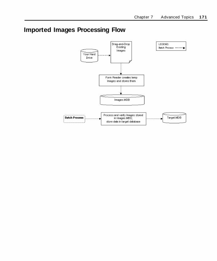
Imported Images Processing Flow
Chapter 7 Advanced Topics 171
SO Chapter 7 Final.qxd 3/21/00 6:28 PM Page 171
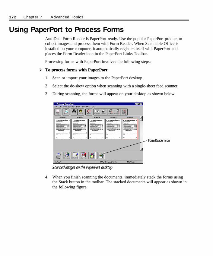
Using PaperPort to Process FormsAutoData Form Reader is PaperPort-ready. Use the popular PaperPort product tocollect images and process them with Form Reader. When Scannable Office isinstalled on your computer, it automatically registers itself with PaperPort andplaces the Form Reader icon in the PaperPort Links Toolbar.
Processing forms with PaperPort involves the following steps:
Ø To process forms with PaperPort:
1. Scan or import your images to the PaperPort desktop.
2. Select the de-skew option when scanning with a single-sheet feed scanner.
3. During scanning, the forms will appear on your desktop as shown below.
Scanned images on the PaperPort desktop
4. When you finish scanning the documents, immediately stack the forms usingthe Stack button in the toolbar. The stacked documents will appear as shown inthe following figure.
172 Chapter 7 Advanced Topics
Form Reader icon
SO Chapter 7 Final.qxd 3/21/00 6:28 PM Page 172
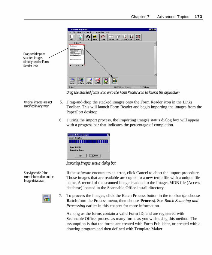
Drag the stacked forms icon onto the Form Reader icon to launch the application
5. Drag-and-drop the stacked images onto the Form Reader icon in the LinksToolbar. This will launch Form Reader and begin importing the images from thePaperPort desktop.
6. During the import process, the Importing Images status dialog box will appearwith a progress bar that indicates the percentage of completion.
Importing Images status dialog box
If the software encounters an error, click Cancel to abort the import procedure.Those images that are readable are copied to a new temp file with a unique filename. A record of the scanned image is added to the Images.MDB file (Accessdatabase) located in the Scannable Office install directory.
7. To process the images, click the Batch Process button in the toolbar (or chooseBatch from the Process menu, then choose Process). See Batch Scanning andProcessing earlier in this chapter for more information.
As long as the forms contain a valid Form ID, and are registered withScannable Office, process as many forms as you wish using this method. Theassumption is that the forms are created with Form Publisher, or created with adrawing program and then defined with Template Maker.
See Appendix D formore information on theImage database.
Original images are notmodified in any way.
Chapter 7 Advanced Topics 173
Drag-and-drop thestacked imagesdirectly on the FormReader icon.
SO Chapter 7 Final.qxd 3/21/00 6:28 PM Page 173
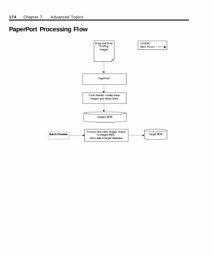
PaperPort Processing Flow
174 Chapter 7 Advanced Topics
SO Chapter 7 Final.qxd 3/21/00 6:28 PM Page 174
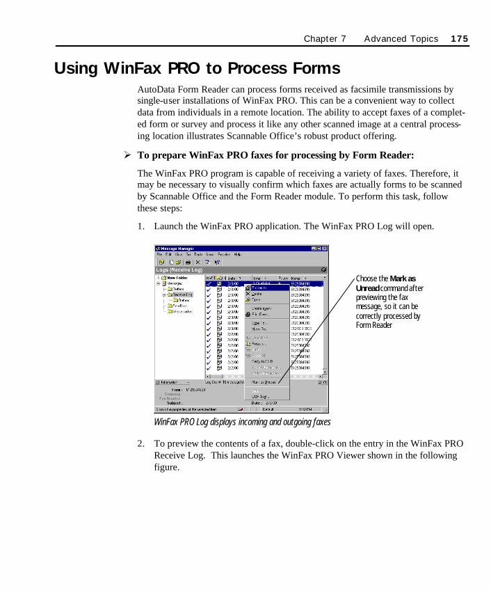
Using WinFax PRO to Process FormsAutoData Form Reader can process forms received as facsimile transmissions bysingle-user installations of WinFax PRO. This can be a convenient way to collectdata from individuals in a remote location. The ability to accept faxes of a complet-ed form or survey and process it like any other scanned image at a central process-ing location illustrates Scannable Office’s robust product offering.
Ø To prepare WinFax PRO faxes for processing by Form Reader:
The WinFax PRO program is capable of receiving a variety of faxes. Therefore, itmay be necessary to visually confirm which faxes are actually forms to be scannedby Scannable Office and the Form Reader module. To perform this task, followthese steps:
1. Launch the WinFax PRO application. The WinFax PRO Log will open.
WinFax PRO Log displays incoming and outgoing faxes
2. To preview the contents of a fax, double-click on the entry in the WinFax PROReceive Log. This launches the WinFax PRO Viewer shown in the followingfigure.
Chapter 7 Advanced Topics 175
Choose the Mark asUnread command afterpreviewing the faxmessage, so it can becorrectly processed byForm Reader
SO Chapter 7 Final.qxd 3/21/00 6:28 PM Page 175
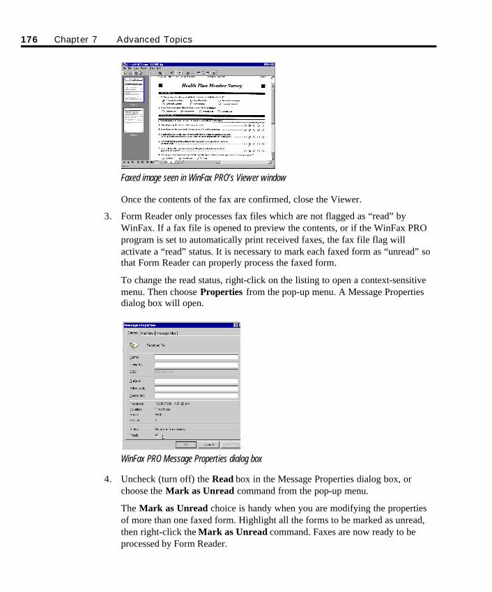
Faxed image seen in WinFax PRO’s Viewer window
Once the contents of the fax are confirmed, close the Viewer.
3. Form Reader only processes fax files which are not flagged as “read” byWinFax. If a fax file is opened to preview the contents, or if the WinFax PROprogram is set to automatically print received faxes, the fax file flag willactivate a “read” status. It is necessary to mark each faxed form as “unread” sothat Form Reader can properly process the faxed form.
To change the read status, right-click on the listing to open a context-sensitivemenu. Then choose Properties from the pop-up menu. A Message Propertiesdialog box will open.
WinFax PRO Message Properties dialog box
4. Uncheck (turn off) the Read box in the Message Properties dialog box, orchoose the Mark as Unread command from the pop-up menu.
The Mark as Unread choice is handy when you are modifying the propertiesof more than one faxed form. Highlight all the forms to be marked as unread,then right-click the Mark as Unread command. Faxes are now ready to beprocessed by Form Reader.
176 Chapter 7 Advanced Topics
SO Chapter 7 Final.qxd 3/21/00 6:28 PM Page 176
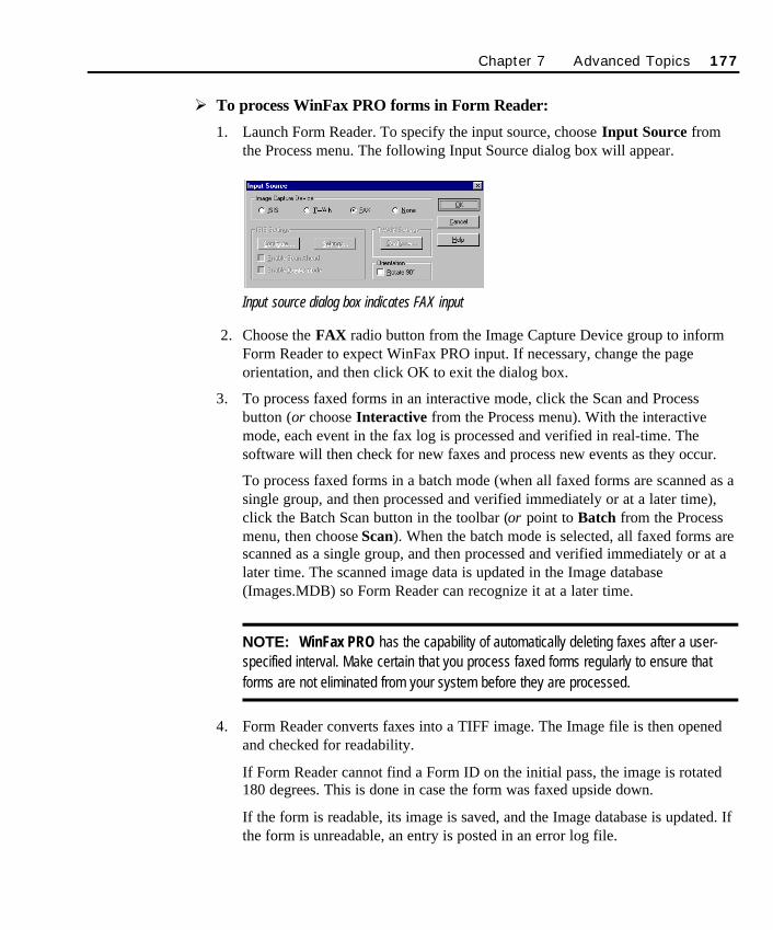
Ø To process WinFax PRO forms in Form Reader:
1. Launch Form Reader. To specify the input source, choose Input Source fromthe Process menu. The following Input Source dialog box will appear.
Input source dialog box indicates FAX input
2. Choose the FAX radio button from the Image Capture Device group to informForm Reader to expect WinFax PRO input. If necessary, change the pageorientation, and then click OK to exit the dialog box.
3. To process faxed forms in an interactive mode, click the Scan and Processbutton (or choose Interactive from the Process menu). With the interactivemode, each event in the fax log is processed and verified in real-time. Thesoftware will then check for new faxes and process new events as they occur.
To process faxed forms in a batch mode (when all faxed forms are scanned as asingle group, and then processed and verified immediately or at a later time),click the Batch Scan button in the toolbar (or point to Batch from the Processmenu, then choose Scan). When the batch mode is selected, all faxed forms arescanned as a single group, and then processed and verified immediately or at alater time. The scanned image data is updated in the Image database(Images.MDB) so Form Reader can recognize it at a later time.
NOTE: WinFax PRO has the capability of automatically deleting faxes after a user-specified interval. Make certain that you process faxed forms regularly to ensure thatforms are not eliminated from your system before they are processed.
4. Form Reader converts faxes into a TIFF image. The Image file is then openedand checked for readability.
If Form Reader cannot find a Form ID on the initial pass, the image is rotated180 degrees. This is done in case the form was faxed upside down.
If the form is readable, its image is saved, and the Image database is updated. Ifthe form is unreadable, an entry is posted in an error log file.
Chapter 7 Advanced Topics 177
SO Chapter 7 Final.qxd 3/21/00 6:28 PM Page 177
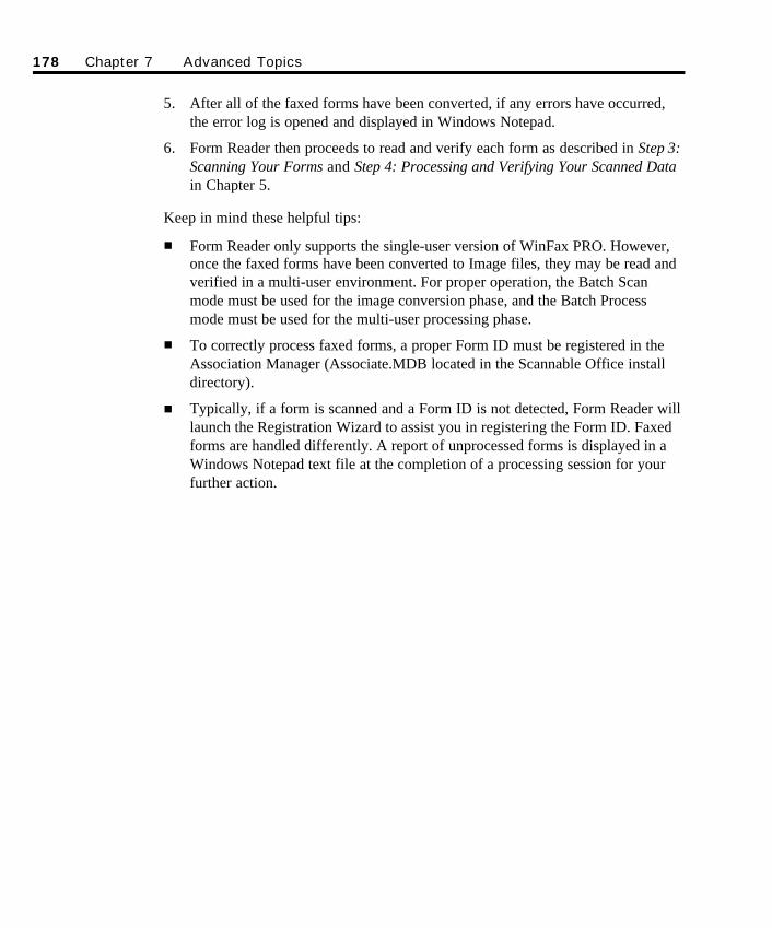
5. After all of the faxed forms have been converted, if any errors have occurred,the error log is opened and displayed in Windows Notepad.
6. Form Reader then proceeds to read and verify each form as described in Step 3:Scanning Your Forms and Step 4: Processing and Verifying Your Scanned Datain Chapter 5.
Keep in mind these helpful tips:
n Form Reader only supports the single-user version of WinFax PRO. However,once the faxed forms have been converted to Image files, they may be read andverified in a multi-user environment. For proper operation, the Batch Scanmode must be used for the image conversion phase, and the Batch Processmode must be used for the multi-user processing phase.
n To correctly process faxed forms, a proper Form ID must be registered in theAssociation Manager (Associate.MDB located in the Scannable Office installdirectory).
n Typically, if a form is scanned and a Form ID is not detected, Form Reader willlaunch the Registration Wizard to assist you in registering the Form ID. Faxedforms are handled differently. A report of unprocessed forms is displayed in aWindows Notepad text file at the completion of a processing session for yourfurther action.
178 Chapter 7 Advanced Topics
SO Chapter 7 Final.qxd 3/21/00 6:28 PM Page 178
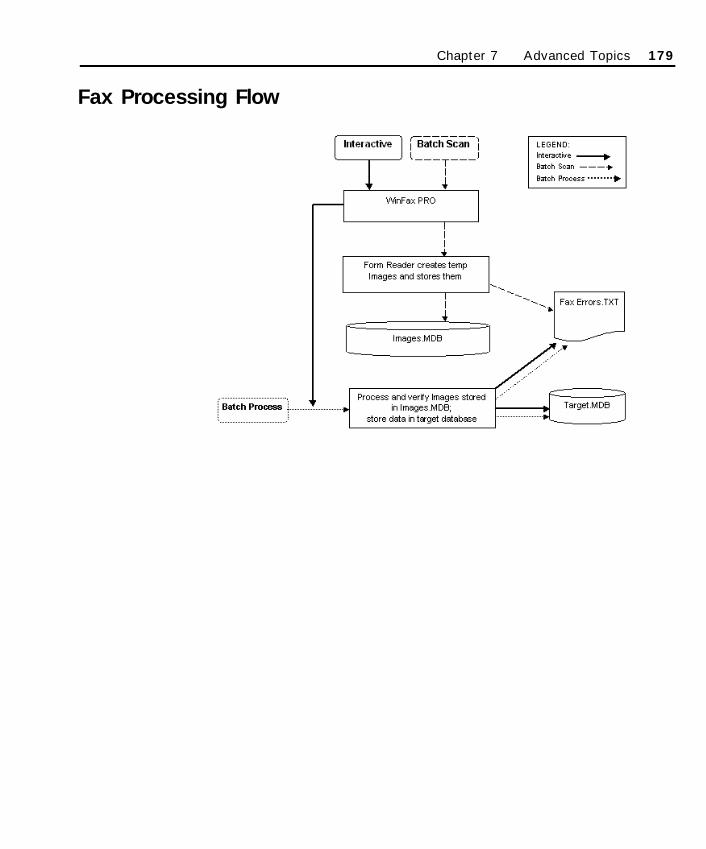
Fax Processing Flow
Chapter 7 Advanced Topics 179
SO Chapter 7 Final.qxd 3/21/00 6:28 PM Page 179
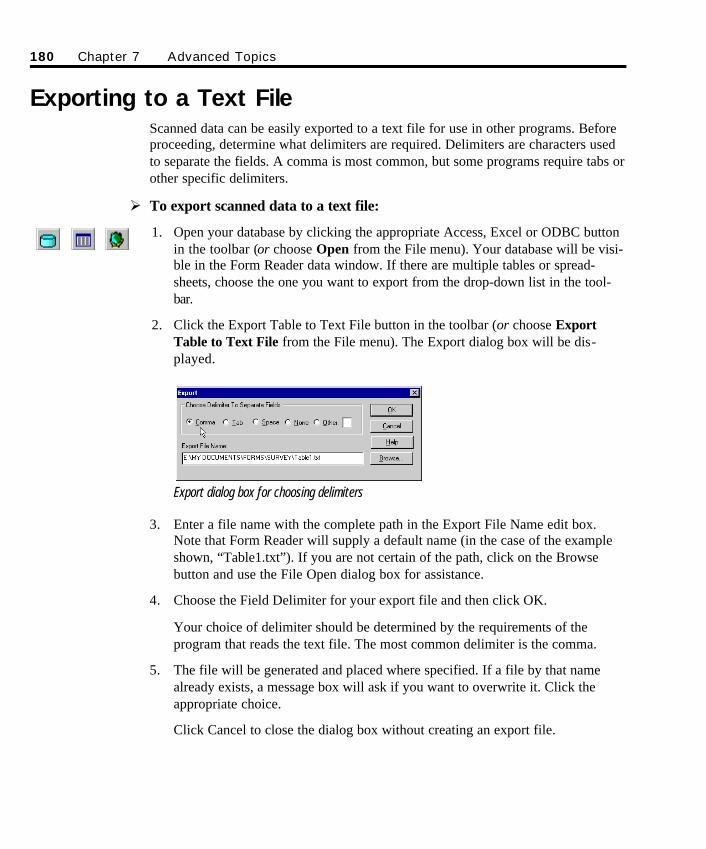
Exporting to a Text FileScanned data can be easily exported to a text file for use in other programs. Beforeproceeding, determine what delimiters are required. Delimiters are characters usedto separate the fields. A comma is most common, but some programs require tabs orother specific delimiters.
Ø To export scanned data to a text file:
1. Open your database by clicking the appropriate Access, Excel or ODBC buttonin the toolbar (or choose Open from the File menu). Your database will be visi-ble in the Form Reader data window. If there are multiple tables or spread-sheets, choose the one you want to export from the drop-down list in the tool-bar.
2. Click the Export Table to Text File button in the toolbar (or choose ExportTable to Text File from the File menu). The Export dialog box will be dis-played.
Export dialog box for choosing delimiters
3. Enter a file name with the complete path in the Export File Name edit box.Note that Form Reader will supply a default name (in the case of the exampleshown, “Table1.txt”). If you are not certain of the path, click on the Browsebutton and use the File Open dialog box for assistance.
4. Choose the Field Delimiter for your export file and then click OK.
Your choice of delimiter should be determined by the requirements of theprogram that reads the text file. The most common delimiter is the comma.
5. The file will be generated and placed where specified. If a file by that namealready exists, a message box will ask if you want to overwrite it. Click theappropriate choice.
Click Cancel to close the dialog box without creating an export file.
180 Chapter 7 Advanced Topics
SO Chapter 7 Final.qxd 3/21/00 6:28 PM Page 180

Merging Serialized Data to a Bar Code or OCR Field
Serializing forms using Scannable Office requires extra thought when creating andprinting the forms. The serialization option provides a unique identifier on eachpage of your form so the information based on the Serial Field is stored in thecorrect database record. The Serial Field ties all the pages of a multi-page documenttogether by using a unique ID. As long as a multi-page form uses the same fieldname on all pages of the form—a requirement if the data is stored in one tablewithin a database—Form Reader will successfully identify each page and associateit with one record within the database. It is recommended that you use either a BarCode Field or an OCR Field to accomplish this task. If you plan to use a SerialField on your form and will be printing a large quantity of the form, consult yourlocal printer to determine if the option of using the Barcode 3 of 9 or WindowsOCR font is supported.
If you plan to use the mail merge capabilities built into Microsoft Word, the type oflaser printer available for this task will limit the number of forms you can print.Refer to the Microsoft Word user manual to fully understand the robust features ofthis tool.
The following example varies slightly from the standard use of the mail mergefunction. This example features a Microsoft Access database (Customer.MDB)containing customer names and unique customer numbers. We will create a BarCode Serial Field on each page of a 2-page document using the customer namefield.
Merging Serialized Data to a Bar CodeØ To create a Bar Code Serial Field on a multi-page form:
1. Before you can add a mail merge field to your form, create or load a data sourcethat will be used to merge field data on your form. Choose Mail Merge fromthe Microsoft Word (or Form Publisher) Tools menu to bring up Mail MergeHelper.
A Serial Field is notsupported by MicrosoftExcel. Make sure yourdatabase sourcerecognizes index fieldsprior to designing aform that contains anytype of Serial Field.
Chapter 7 Advanced Topics 181
SO Chapter 7 Final.qxd 3/21/00 6:28 PM Page 181
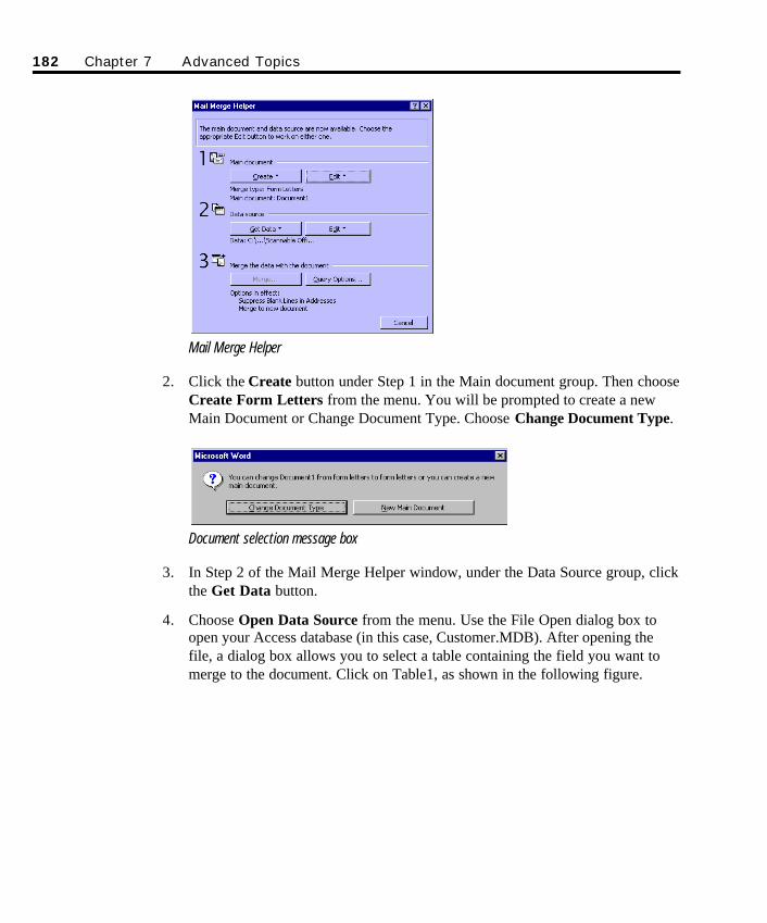
Mail Merge Helper
2. Click the Create button under Step 1 in the Main document group. Then chooseCreate Form Letters from the menu. You will be prompted to create a newMain Document or Change Document Type. Choose Change Document Type.
Document selection message box
3. In Step 2 of the Mail Merge Helper window, under the Data Source group, clickthe Get Data button.
4. Choose Open Data Source from the menu. Use the File Open dialog box toopen your Access database (in this case, Customer.MDB). After opening thefile, a dialog box allows you to select a table containing the field you want tomerge to the document. Click on Table1, as shown in the following figure.
182 Chapter 7 Advanced Topics
SO Chapter 7 Final.qxd 3/21/00 6:28 PM Page 182
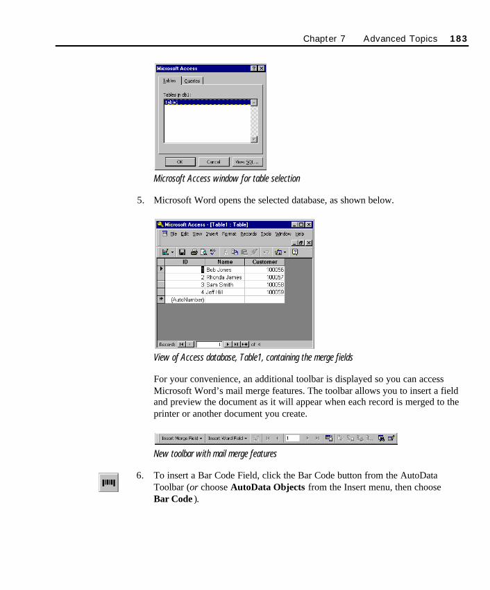
Microsoft Access window for table selection
5. Microsoft Word opens the selected database, as shown below.
View of Access database, Table1, containing the merge fields
For your convenience, an additional toolbar is displayed so you can accessMicrosoft Word’s mail merge features. The toolbar allows you to insert a fieldand preview the document as it will appear when each record is merged to theprinter or another document you create.
New toolbar with mail merge features
6. To insert a Bar Code Field, click the Bar Code button from the AutoDataToolbar (or choose AutoData Objects from the Insert menu, then choose Bar Code ).
Chapter 7 Advanced Topics 183
SO Chapter 7 Final.qxd 3/21/00 6:28 PM Page 183
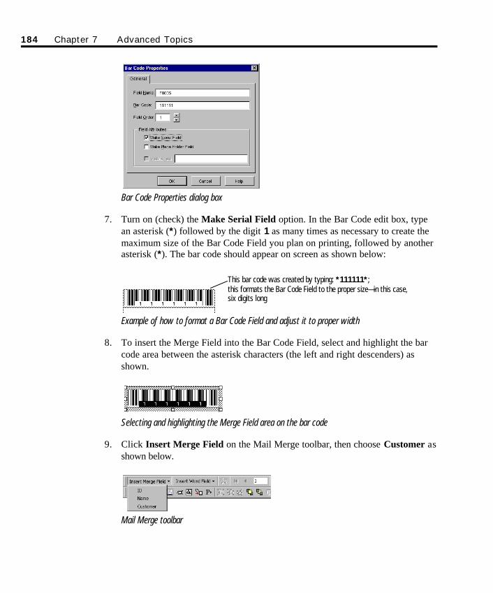
Bar Code Properties dialog box
7. Turn on (check) the Make Serial Field option. In the Bar Code edit box, typean asterisk (*) followed by the digit 1 as many times as necessary to create themaximum size of the Bar Code Field you plan on printing, followed by anotherasterisk (*). The bar code should appear on screen as shown below:
Example of how to format a Bar Code Field and adjust it to proper width
8. To insert the Merge Field into the Bar Code Field, select and highlight the barcode area between the asterisk characters (the left and right descenders) asshown.
Selecting and highlighting the Merge Field area on the bar code
9. Click Insert Merge Field on the Mail Merge toolbar, then choose Customer asshown below.
Mail Merge toolbar
184 Chapter 7 Advanced Topics
This bar code was created by typing: *111111*;this formats the Bar Code Field to the proper size—in this case,six digits long
SO Chapter 7 Final.qxd 3/21/00 6:28 PM Page 184
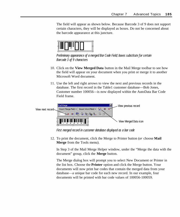
The field will appear as shown below. Because Barcode 3 of 9 does not supportcertain characters, they will be displayed as boxes. Do not be concerned aboutthe barcode appearance at this juncture.
Preliminary appearance of a merged Bar Code Field; boxes substitute for certain Barcode 3 of 9 characters
10. Click on the View Merged Data button in the Mail Merge toolbar to see howthe field will appear on your document when you print or merge it to anotherMicrosoft Word document.
11. Use the left and right arrows to view the next and previous records in thedatabase. The first record in the Table1 customer database—Bob Jones,Customer number 100056—is now displayed within the AutoData Bar CodeField frame.
First merged record in customer database displayed as a bar code
12. To print the document, click the Merge to Printer button (or choose MailMerge from the Tools menu).
In Step 3 of the Mail Merge Helper window, under the “Merge the data with thedocument” group, click the Merge button.
The Merge dialog box will prompt you to select New Document or Printer inthe list box. Choose the Printer option and click the Merge button. Yourdocuments will now print bar codes that contain the merged data from yourdatabase—a unique bar code for each new record. In our example, fourdocuments will be printed with bar code values of 100056-100059.
Chapter 7 Advanced Topics 185
View previous recordView next record
View Merged Data icon
SO Chapter 7 Final.qxd 3/21/00 6:28 PM Page 185
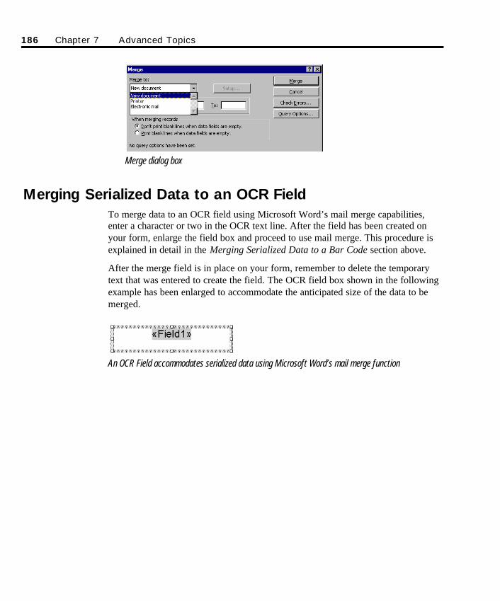
Merge dialog box
Merging Serialized Data to an OCR FieldTo merge data to an OCR field using Microsoft Word’s mail merge capabilities,enter a character or two in the OCR text line. After the field has been created onyour form, enlarge the field box and proceed to use mail merge. This procedure isexplained in detail in the Merging Serialized Data to a Bar Code section above.
After the merge field is in place on your form, remember to delete the temporarytext that was entered to create the field. The OCR field box shown in the followingexample has been enlarged to accommodate the anticipated size of the data to bemerged.
An OCR Field accommodates serialized data using Microsoft Word’s mail merge function
186 Chapter 7 Advanced Topics
SO Chapter 7 Final.qxd 3/21/00 6:28 PM Page 186
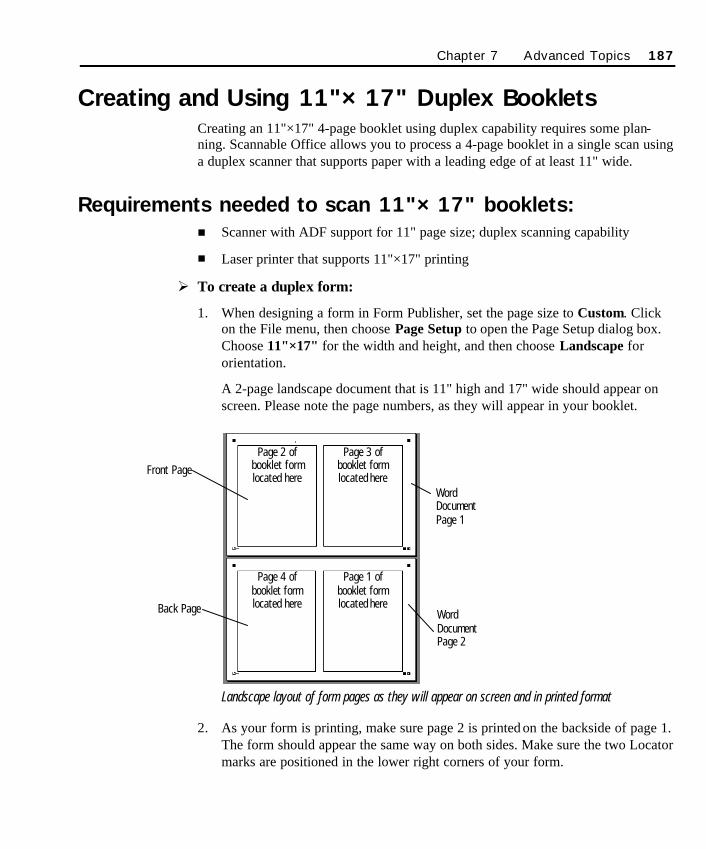
Creating and Using 11"×17" Duplex BookletsCreating an 11"×17" 4-page booklet using duplex capability requires some plan-ning. Scannable Office allows you to process a 4-page booklet in a single scan usinga duplex scanner that supports paper with a leading edge of at least 11" wide.
Requirements needed to scan 11"×17" booklets:n Scanner with ADF support for 11" page size; duplex scanning capability
n Laser printer that supports 11"×17" printing
Ø To create a duplex form:
1. When designing a form in Form Publisher, set the page size to Custom. Clickon the File menu, then choose Page Setup to open the Page Setup dialog box.Choose 11"×17" for the width and height, and then choose Landscape fororientation.
A 2-page landscape document that is 11" high and 17" wide should appear onscreen. Please note the page numbers, as they will appear in your booklet.
Landscape layout of form pages as they will appear on screen and in printed format
2. As your form is printing, make sure page 2 is printed on the backside of page 1.The form should appear the same way on both sides. Make sure the two Locatormarks are positioned in the lower right corners of your form.
Chapter 7 Advanced Topics 187
Front Page
WordDocumentPage 1
Back Page WordDocumentPage 2
Page 2 of booklet formlocated here
Page 3 of booklet formlocated here
Page 4 of booklet formlocated here
Page 1 of booklet formlocated here
SO Chapter 7 Final.qxd 3/21/00 6:28 PM Page 187
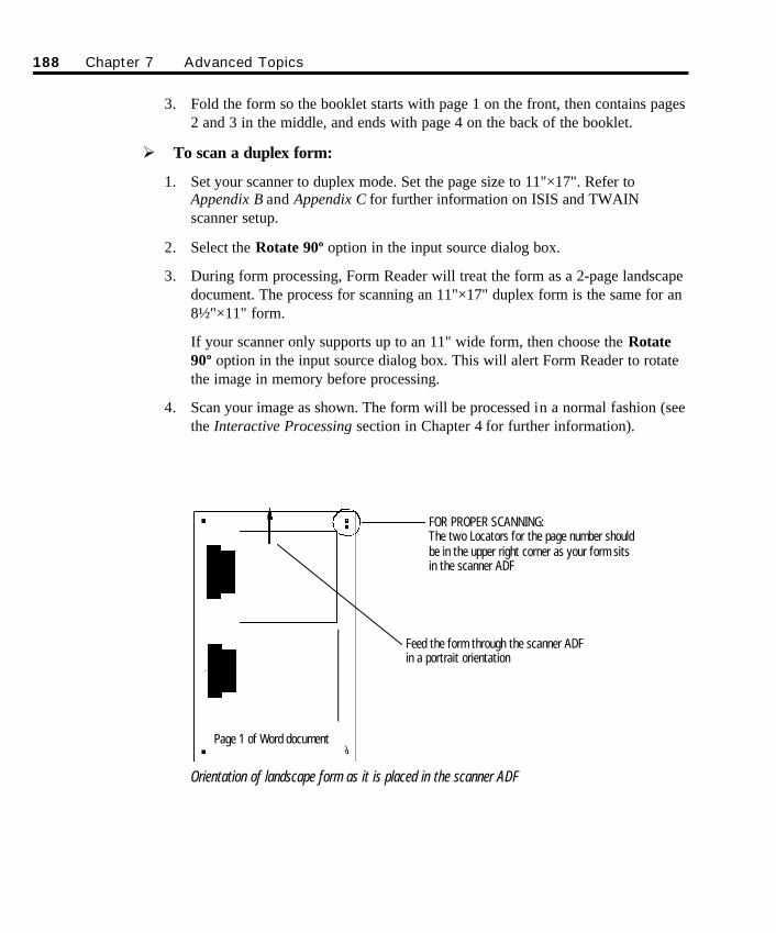
3. Fold the form so the booklet starts with page 1 on the front, then contains pages2 and 3 in the middle, and ends with page 4 on the back of the booklet.
Ø To scan a duplex form:
1. Set your scanner to duplex mode. Set the page size to 11"×17". Refer toAppendix B and Appendix C for further information on ISIS and TWAINscanner setup.
2. Select the Rotate 90º option in the input source dialog box.
3. During form processing, Form Reader will treat the form as a 2-page landscapedocument. The process for scanning an 11"×17" duplex form is the same for an8½"×11" form.
If your scanner only supports up to an 11" wide form, then choose the Rotate90º option in the input source dialog box. This will alert Form Reader to rotatethe image in memory before processing.
4. Scan your image as shown. The form will be processed in a normal fashion (seethe Interactive Processing section in Chapter 4 for further information).
Orientation of landscape form as it is placed in the scanner ADF
188 Chapter 7 Advanced Topics
FOR PROPER SCANNING:The two Locators for the page number shouldbe in the upper right corner as your form sitsin the scanner ADF
Feed the form through the scanner ADFin a portrait orientation
Page 1 of Word document
SO Chapter 7 Final.qxd 3/21/00 6:28 PM Page 188
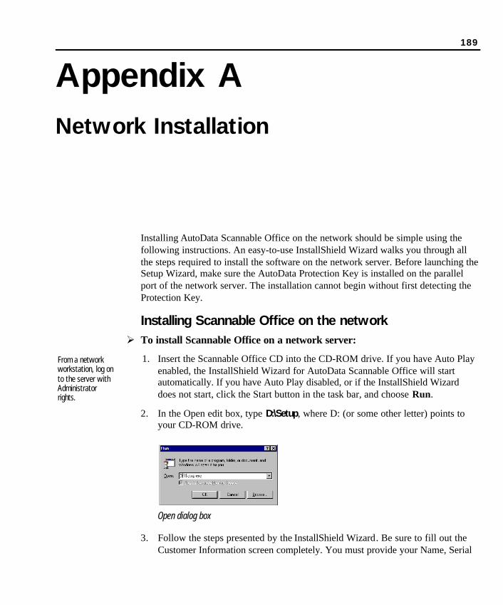
189
Appendix ANetwork Installation
Installing AutoData Scannable Office on the network should be simple using thefollowing instructions. An easy-to-use InstallShield Wizard walks you through allthe steps required to install the software on the network server. Before launching theSetup Wizard, make sure the AutoData Protection Key is installed on the parallelport of the network server. The installation cannot begin without first detecting theProtection Key.
Installing Scannable Office on the networkØ To install Scannable Office on a network server:
1. Insert the Scannable Office CD into the CD-ROM drive. If you have Auto Playenabled, the InstallShield Wizard for AutoData Scannable Office will startautomatically. If you have Auto Play disabled, or if the InstallShield Wizarddoes not start, click the Start button in the task bar, and choose Run.
2. In the Open edit box, type D:\Setup, where D: (or some other letter) points toyour CD-ROM drive.
Open dialog box
3. Follow the steps presented by the InstallShield Wizard. Be sure to fill out theCustomer Information screen completely. You must provide your Name, Serial
From a networkworkstation, log onto the server withAdministratorrights.
SO Appendix A Final.qxd 3/21/00 6:09 PM Page 189
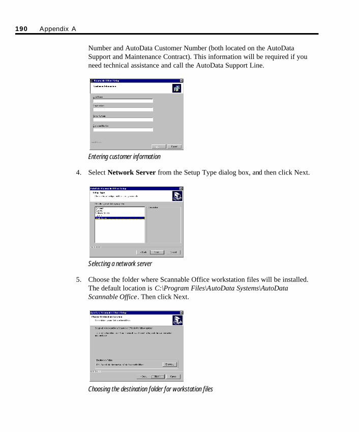
190 Appendix A
Number and AutoData Customer Number (both located on the AutoDataSupport and Maintenance Contract). This information will be required if youneed technical assistance and call the AutoData Support Line.
Entering customer information
4. Select Network Server from the Setup Type dialog box, and then click Next.
Selecting a network server
5. Choose the folder where Scannable Office workstation files will be installed.The default location is C:\Program Files\AutoData Systems\AutoDataScannable Office. Then click Next.
Choosing the destination folder for workstation files
SO Appendix A Final.qxd 3/21/00 6:09 PM Page 190
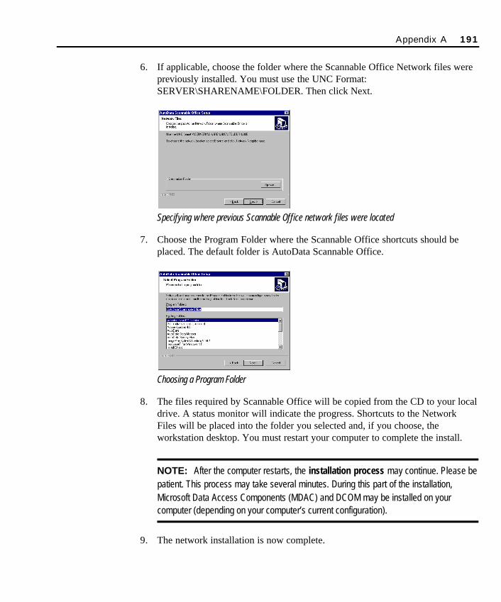
6. If applicable, choose the folder where the Scannable Office Network files werepreviously installed. You must use the UNC Format:SERVER\SHARENAME\FOLDER. Then click Next.
Specifying where previous Scannable Office network files were located
7. Choose the Program Folder where the Scannable Office shortcuts should beplaced. The default folder is AutoData Scannable Office.
Choosing a Program Folder
8. The files required by Scannable Office will be copied from the CD to your localdrive. A status monitor will indicate the progress. Shortcuts to the NetworkFiles will be placed into the folder you selected and, if you choose, theworkstation desktop. You must restart your computer to complete the install.
NOTE: After the computer restarts, the installation process may continue. Please bepatient. This process may take several minutes. During this part of the installation,Microsoft Data Access Components (MDAC) and DCOM may be installed on yourcomputer (depending on your computer’s current configuration).
9. The network installation is now complete.
Appendix A 191
SO Appendix A Final.qxd 3/21/00 6:09 PM Page 191

192 Appendix A
SO Appendix A Final.qxd 3/21/00 6:09 PM Page 192
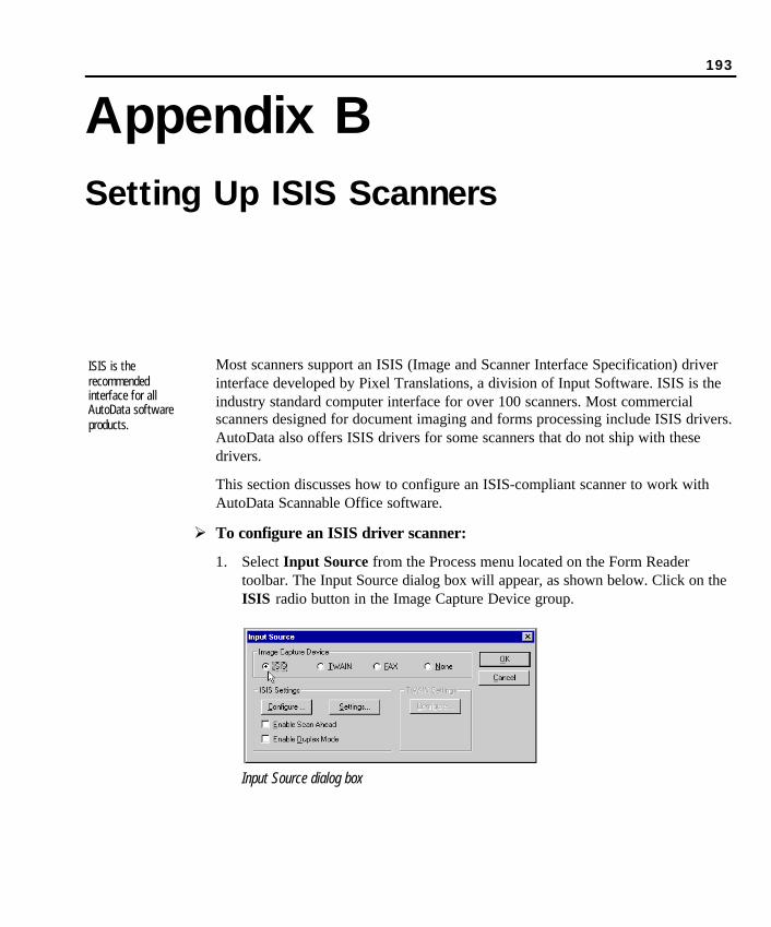
193
Appendix BSetting Up ISIS Scanners
Most scanners support an ISIS (Image and Scanner Interface Specification) driverinterface developed by Pixel Translations, a division of Input Software. ISIS is theindustry standard computer interface for over 100 scanners. Most commercialscanners designed for document imaging and forms processing include ISIS drivers.AutoData also offers ISIS drivers for some scanners that do not ship with thesedrivers.
This section discusses how to configure an ISIS-compliant scanner to work withAutoData Scannable Office software.
Ø To configure an ISIS driver scanner:
1. Select Input Source from the Process menu located on the Form Readertoolbar. The Input Source dialog box will appear, as shown below. Click on theISIS radio button in the Image Capture Device group.
Input Source dialog box
ISIS is therecommendedinterface for allAutoData softwareproducts.
SO Appendix B Final.qxd 3/21/00 6:11 PM Page 193
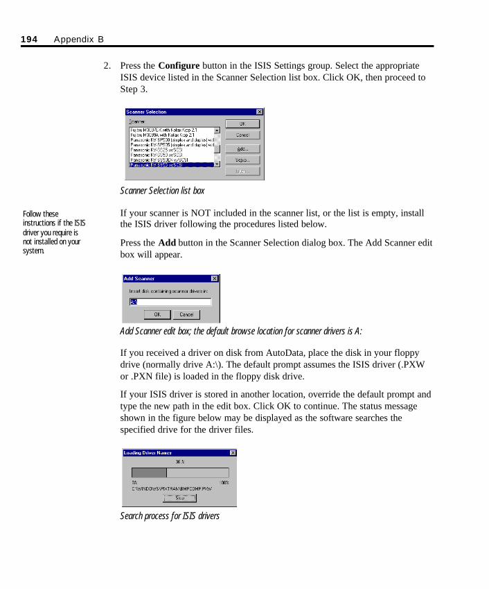
194 Appendix B
2. Press the Configure button in the ISIS Settings group. Select the appropriateISIS device listed in the Scanner Selection list box. Click OK, then proceed toStep 3.
Scanner Selection list box
If your scanner is NOT included in the scanner list, or the list is empty, installthe ISIS driver following the procedures listed below.
Press the Add button in the Scanner Selection dialog box. The Add Scanner editbox will appear.
Add Scanner edit box; the default browse location for scanner drivers is A:
If you received a driver on disk from AutoData, place the disk in your floppydrive (normally drive A:\). The default prompt assumes the ISIS driver (.PXWor .PXN file) is loaded in the floppy disk drive.
If your ISIS driver is stored in another location, override the default prompt andtype the new path in the edit box. Click OK to continue. The status messageshown in the figure below may be displayed as the software searches thespecified drive for the driver files.
Search process for ISIS drivers
Follow theseinstructions if the ISISdriver you require isnot installed on yoursystem.
SO Appendix B Final.qxd 3/21/00 6:11 PM Page 194
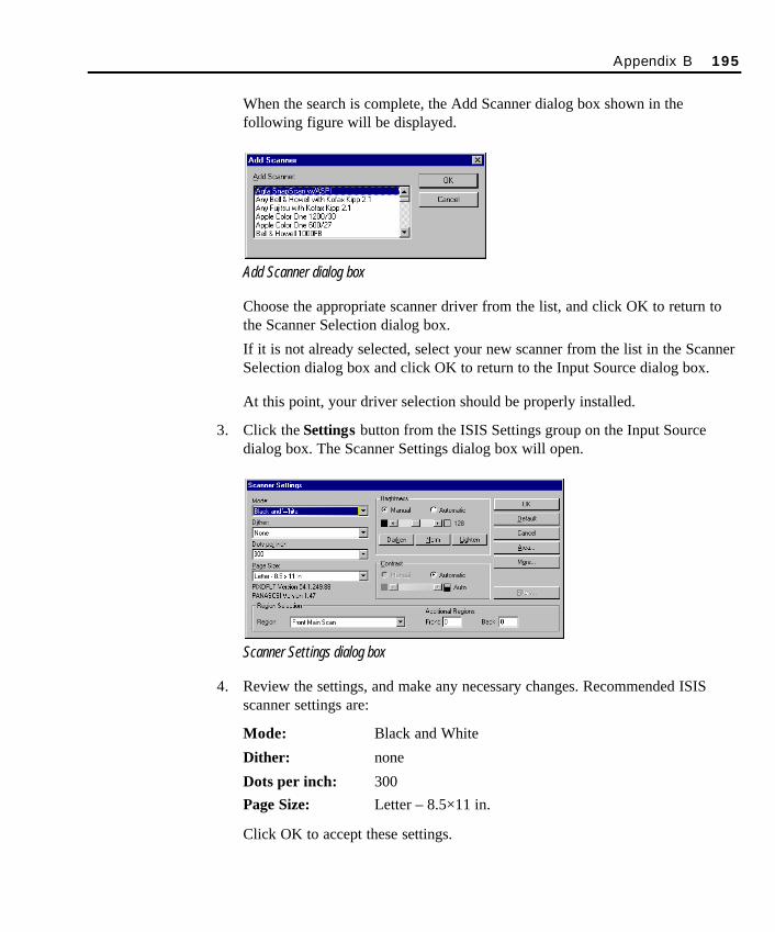
When the search is complete, the Add Scanner dialog box shown in thefollowing figure will be displayed.
Add Scanner dialog box
Choose the appropriate scanner driver from the list, and click OK to return tothe Scanner Selection dialog box.
If it is not already selected, select your new scanner from the list in the ScannerSelection dialog box and click OK to return to the Input Source dialog box.
At this point, your driver selection should be properly installed.
3. Click the Settings button from the ISIS Settings group on the Input Sourcedialog box. The Scanner Settings dialog box will open.
Scanner Settings dialog box
4. Review the settings, and make any necessary changes. Recommended ISISscanner settings are:
Mode: Black and White
Dither: none
Dots per inch: 300Page Size: Letter – 8.5×11 in.
Click OK to accept these settings.
Appendix B 195
SO Appendix B Final.qxd 3/21/00 6:11 PM Page 195
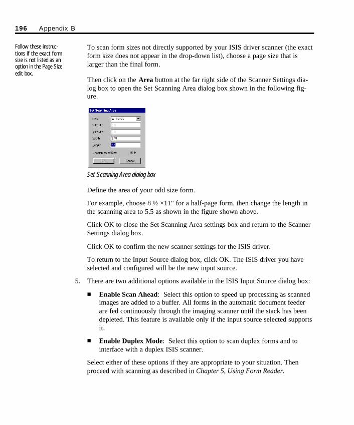
To scan form sizes not directly supported by your ISIS driver scanner (the exactform size does not appear in the drop-down list), choose a page size that islarger than the final form.
Then click on the Area button at the far right side of the Scanner Settings dia-log box to open the Set Scanning Area dialog box shown in the following fig-ure.
Set Scanning Area dialog box
Define the area of your odd size form.
For example, choose 8 ½ ×11" for a half-page form, then change the length inthe scanning area to 5.5 as shown in the figure shown above.
Click OK to close the Set Scanning Area settings box and return to the ScannerSettings dialog box.
Click OK to confirm the new scanner settings for the ISIS driver.
To return to the Input Source dialog box, click OK. The ISIS driver you haveselected and configured will be the new input source.
5. There are two additional options available in the ISIS Input Source dialog box:
n Enable Scan Ahead: Select this option to speed up processing as scannedimages are added to a buffer. All forms in the automatic document feederare fed continuously through the imaging scanner until the stack has beendepleted. This feature is available only if the input source selected supportsit.
n Enable Duplex Mode: Select this option to scan duplex forms and tointerface with a duplex ISIS scanner.
Select either of these options if they are appropriate to your situation. Thenproceed with scanning as described in Chapter 5, Using Form Reader.
196 Appendix B
Follow these instruc-tions if the exact formsize is not listed as anoption in the Page Sizeedit box.
SO Appendix B Final.qxd 3/21/00 6:11 PM Page 196
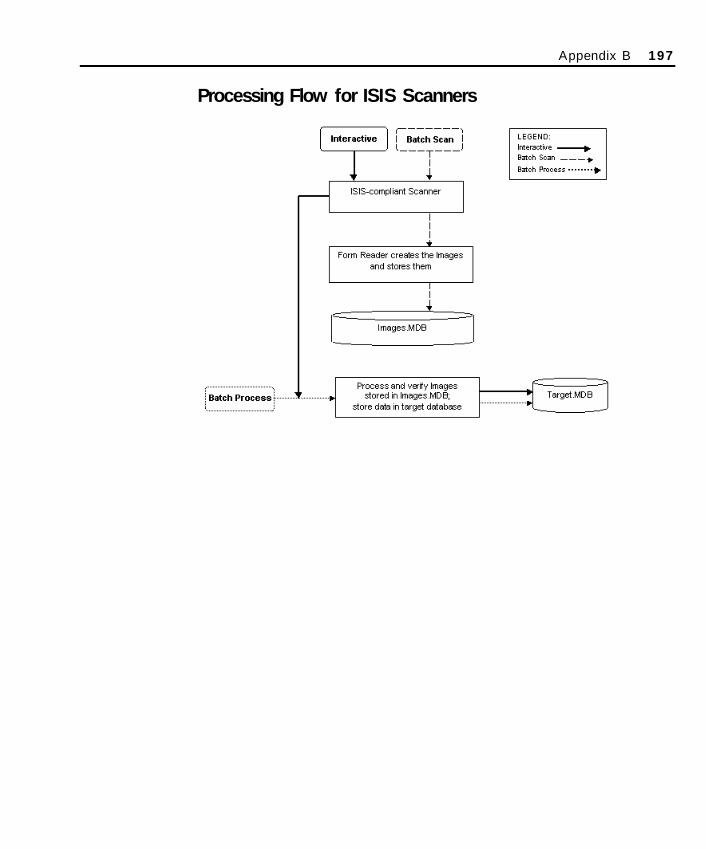
Processing Flow for ISIS Scanners
Appendix B 197
SO Appendix B Final.qxd 3/21/00 6:11 PM Page 197

198 Appendix B
SO Appendix B Final.qxd 3/21/00 6:11 PM Page 198
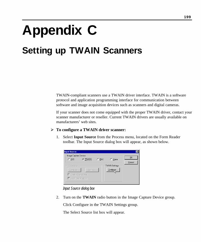
199
Appendix CSetting up TWAIN Scanners
TWAIN-compliant scanners use a TWAIN driver interface. TWAIN is a softwareprotocol and application programming interface for communication betweensoftware and image acquisition devices such as scanners and digital cameras.
If your scanner does not come equipped with the proper TWAIN driver, contact yourscanner manufacturer or reseller. Current TWAIN drivers are usually available onmanufacturers’ web sites.
Ø To configure a TWAIN driver scanner:
1. Select Input Source from the Process menu, located on the Form Readertoolbar. The Input Source dialog box will appear, as shown below.
Input Source dialog box
2. Turn on the TWAIN radio button in the Image Capture Device group.
Click Configure in the TWAIN Settings group.
The Select Source list box will appear.
SO Appendix C Final.qxd 3/21/00 5:42 PM Page 199
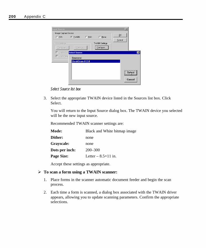
200 Appendix C
Select Source list box
3. Select the appropriate TWAIN device listed in the Sources list box. ClickSelect.
You will return to the Input Source dialog box. The TWAIN device you selectedwill be the new input source.
Recommended TWAIN scanner settings are:
Mode: Black and White bitmap image
Dither: noneGrayscale: none
Dots per inch: 200–300Page Size: Letter – 8.5×11 in.
Accept these settings as appropriate.
Ø To scan a form using a TWAIN scanner:
1. Place forms in the scanner automatic document feeder and begin the scanprocess.
2. Each time a form is scanned, a dialog box associated with the TWAIN driverappears, allowing you to update scanning parameters. Confirm the appropriateselections.
SO Appendix C Final.qxd 3/21/00 5:42 PM Page 200
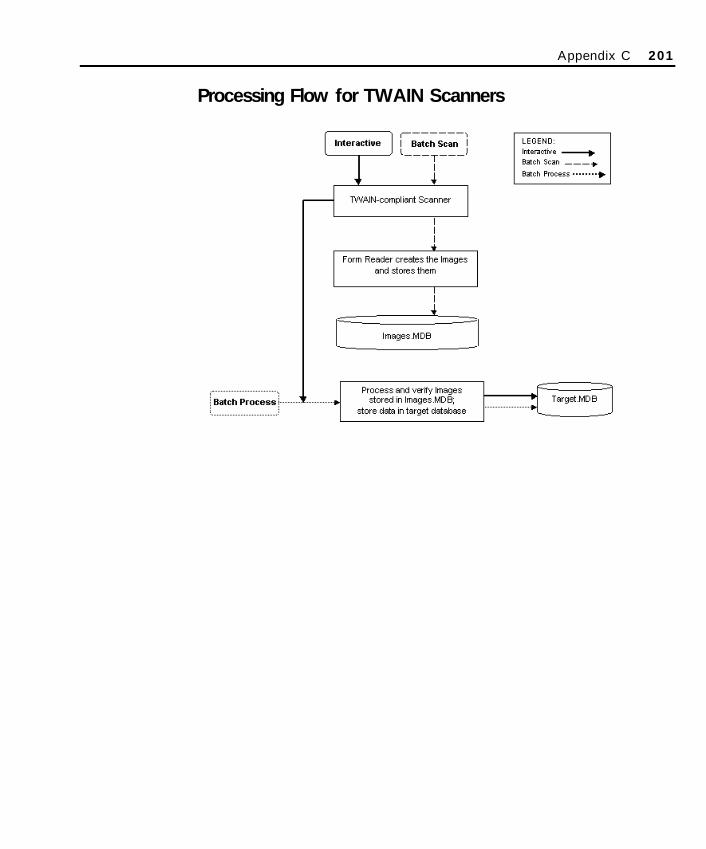
Processing Flow for TWAIN Scanners
Appendix C 201
SO Appendix C Final.qxd 3/21/00 5:42 PM Page 201

202 Appendix C
SO Appendix C Final.qxd 3/21/00 5:42 PM Page 202
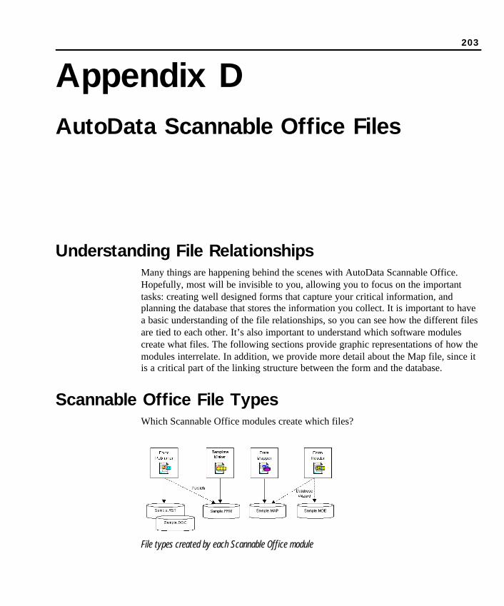
203
Appendix DAutoData Scannable Office Files
Understanding File RelationshipsMany things are happening behind the scenes with AutoData Scannable Office.Hopefully, most will be invisible to you, allowing you to focus on the importanttasks: creating well designed forms that capture your critical information, andplanning the database that stores the information you collect. It is important to havea basic understanding of the file relationships, so you can see how the different filesare tied to each other. It’s also important to understand which software modulescreate what files. The following sections provide graphic representations of how themodules interrelate. In addition, we provide more detail about the Map file, since itis a critical part of the linking structure between the form and the database.
Scannable Office File TypesWhich Scannable Office modules create which files?
File types created by each Scannable Office module
SO Appendix D Final.qxd 3/21/00 6:11 PM Page 203
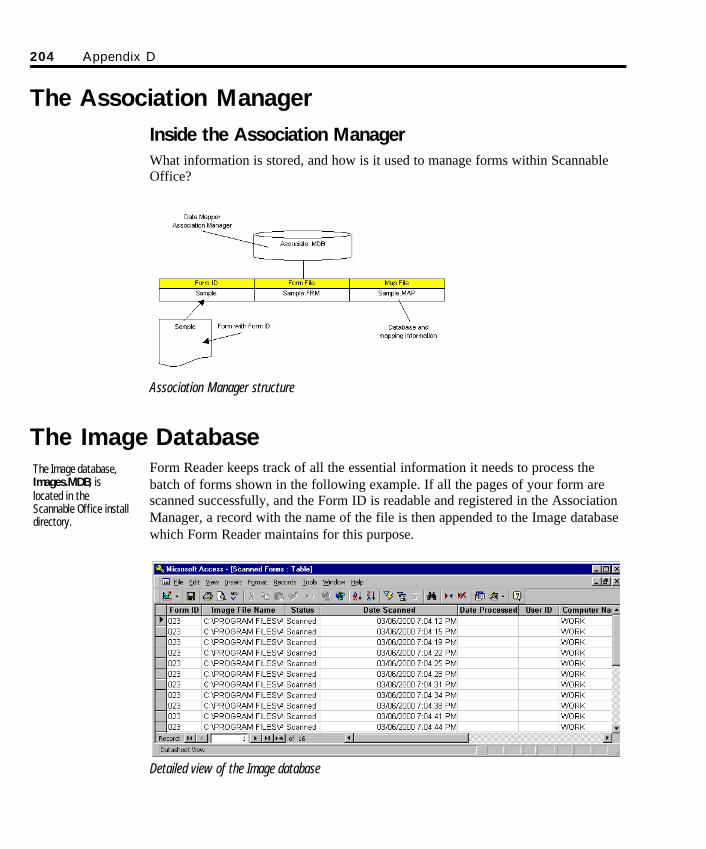
204 Appendix D
The Association ManagerInside the Association ManagerWhat information is stored, and how is it used to manage forms within ScannableOffice?
Association Manager structure
The Image DatabaseForm Reader keeps track of all the essential information it needs to process thebatch of forms shown in the following example. If all the pages of your form arescanned successfully, and the Form ID is readable and registered in the AssociationManager, a record with the name of the file is then appended to the Image databasewhich Form Reader maintains for this purpose.
Detailed view of the Image database
The Image database,Images.MDB, islocated in theScannable Office installdirectory.
SO Appendix D Final.qxd 3/21/00 6:11 PM Page 204
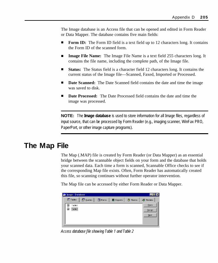
The Image database is an Access file that can be opened and edited in Form Readeror Data Mapper. The database contains five main fields:
n Form ID: The Form ID field is a text field up to 12 characters long. It containsthe Form ID of the scanned form.
n Image File Name: The Image File Name is a text field 255 characters long. Itcontains the file name, including the complete path, of the Image file.
n Status: The Status field is a character field 12 characters long. It contains thecurrent status of the Image file—Scanned, Faxed, Imported or Processed.
n Date Scanned: The Date Scanned field contains the date and time the imagewas saved to disk.
n Date Processed: The Date Processed field contains the date and time theimage was processed.
NOTE: The Image database is used to store information for all Image files, regardless ofinput source, that can be processed by Form Reader (e.g., imaging scanner, WinFax PRO,PaperPort, or other image capture programs).
The Map FileThe Map (.MAP) file is created by Form Reader (or Data Mapper) as an essentialbridge between the scannable object fields on your form and the database that holdsyour scanned data. Each time a form is scanned, Scannable Office checks to see ifthe corresponding Map file exists. Often, Form Reader has automatically createdthis file, so scanning continues without further operator intervention.
The Map file can be accessed by either Form Reader or Data Mapper.
Access database file showing Table 1 and Table 2
Appendix D 205
SO Appendix D Final.qxd 3/21/00 6:11 PM Page 205
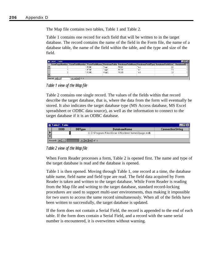
The Map file contains two tables, Table 1 and Table 2.
Table 1 contains one record for each field that will be written to in the targetdatabase. The record contains the name of the field in the Form file, the name of adatabase table, the name of the field within the table, and the type and size of thefield.
Table 1 view of the Map file
Table 2 contains one single record. The values of the fields within that recorddescribe the target database, that is, where the data from the form will eventually bestored. It also indicates the target database type (MS Access database, MS Excelspreadsheet or ODBC data source), as well as the information to connect to thetarget database if it is an ODBC database.
Table 2 view of the Map file
When Form Reader processes a form, Table 2 is opened first. The name and type ofthe target database is read and the database is opened.
Table 1 is then opened. Moving through Table 1, one record at a time, the databasetable name, field name and field type are read. The field data acquired by FormReader is taken and written to the target database. While Form Reader is readingfrom the Map file and writing to the target database, standard record-lockingprocedures are used to support multi-user environments, thus making it impossiblefor two users to access the same record simultaneously. When all of the fields havebeen written to successfully, the target database is updated.
If the form does not contain a Serial Field, the record is appended to the end of eachtable. If the form does contain a Serial Field, and a record with the same serialnumber is encountered, it is overwritten without warning.
206 Appendix D
SO Appendix D Final.qxd 3/21/00 6:11 PM Page 206

207
Appendix EAutoData SmartMemory TechnicalDescription
AutoData’s patented SmartMemory™ technology is the processing engine forrecognizing hand printed characters. Unique features of SmartMemory enable highrecognition rates, and the unique ability to improve recognition over time byadapting to the specific hand print styles of form respondents.
Origin of TechnologySmartMemory technology originated from a model of biological neural networksthat processes visual patterns of information. The information processing propertiesof the biological model were incorporated in an algorithm and implemented in thecomputer software called AutoData SmartMemory.
The neural network property from which SmartMemory derives its power andestablishes its uniqueness is associative recall. SmartMemory has evolved over thepast 10 years to be the most powerful pattern recognition technology available. Ithas also been used in other applications, including machine vision and imagecompression.
SmartMemory and Associative RecallAssociative recall is best described by comparing human visual pattern recognitionwith conventional computer methods that do not use SmartMemory. Our humanvisual system has an immense capacity to recognize visual patterns, and wecontinually learn to recognize new visual patterns in our environment. If human
SO Appendix E Final.qxd 3/21/00 6:12 PM Page 207
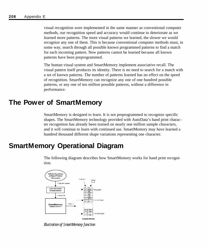
208 Appendix E
visual recognition were implemented in the same manner as conventional computermethods, our recognition speed and accuracy would continue to deteriorate as welearned more patterns. The more visual patterns we learned, the slower we wouldrecognize any one of them. This is because conventional computer methods must, insome way, search through all possible known programmed patterns to find a matchfor each incoming pattern. New patterns cannot be learned because all knownpatterns have been preprogrammed.
The human visual system and SmartMemory implement associative recall. Thevisual pattern itself produces its identity. There is no need to search for a match witha set of known patterns. The number of patterns learned has no effect on the speedof recognition. SmartMemory can recognize any one of one hundred possiblepatterns, or any one of ten million possible patterns, without a difference inperformance.
The Power of SmartMemory
SmartMemory is designed to learn. It is not preprogrammed to recognize specificshapes. The SmartMemory technology provided with AutoData’s hand print charac-ter recognition has already been trained on nearly one million sample characters,and it will continue to learn with continued use. SmartMemory may have learned ahundred thousand different shape variations representing one character.
SmartMemory Operational Diagram
The following diagram describes how SmartMemory works for hand print recogni-tion.
Illustration of SmartMemory function
SO Appendix E Final.qxd 3/21/00 6:12 PM Page 208
Low Level Feature Sensing: Each scanned character is processed by the FeatureSensing software. Generic shape features such as edges, curvatures, enclosures, etc.,are sensed and converted to a feature set.
SmartMemory Software: There are an infinite number of possible feature sets.SmartMemory associates any feature set with a unique Shape ID that is also aunique computer memory address.
Computer Memory: The unique computer memory address contains the actualcharacter and the shape count. The shape count is the number of times this specificshape has occurred for this character.
Recognized Character: A character will be recognized if the shape count is highfor this character.
Low Confidence: If the shape count for this character is low, the character will bepresented to the operator for verification. Verification will increment the count andgive greater confidence to the shape for this character on subsequent occurrences.
Unknown Shapes: In some cases a Shape ID will be generated which has neveroccurred before (shape count = 0). In this case the operator is presented with a “?”and the character entered is stored with the shape count of 1.
Character Training: There is an option to select the Soft Train or Hard Trainmode. Technically, they differ only by the amount the shape count is incrementedfor each verification character entered.
n Soft Train mode increments the shape count by a single count while Hard Trainmode increments it by many counts. Soft Train mode is recommended fornormal operation because, over time, it will reflect the true statistics of shapeoccurrences for characters. In addition, this mode is immune to occasionalverification errors. A verification error occurs if the character image to beverified is legitimately a different character than was entered.
n Hard Train mode allows faster learning but could jeopardize the integrity ofthe SmartMemory if verification errors occur.
Appendix E 209
SO Appendix E Final.qxd 3/21/00 6:12 PM Page 209

210 Appendix E
SO Appendix E Final.qxd 3/21/00 6:12 PM Page 210
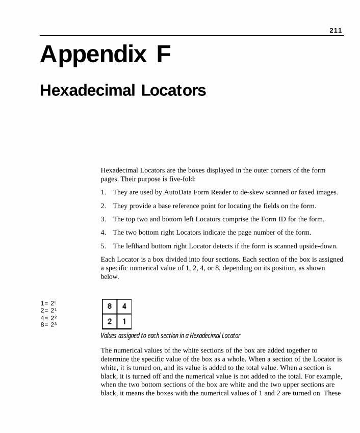
211
Appendix FHexadecimal Locators
Hexadecimal Locators are the boxes displayed in the outer corners of the formpages. Their purpose is five-fold:
1. They are used by AutoData Form Reader to de-skew scanned or faxed images.
2. They provide a base reference point for locating the fields on the form.
3. The top two and bottom left Locators comprise the Form ID for the form.
4. The two bottom right Locators indicate the page number of the form.
5. The lefthand bottom right Locator detects if the form is scanned upside-down.
Each Locator is a box divided into four sections. Each section of the box is assigneda specific numerical value of 1, 2, 4, or 8, depending on its position, as shownbelow.
Values assigned to each section in a Hexadecimal Locator
The numerical values of the white sections of the box are added together todetermine the specific value of the box as a whole. When a section of the Locator iswhite, it is turned on, and its value is added to the total value. When a section isblack, it is turned off and the numerical value is not added to the total. For example,when the two bottom sections of the box are white and the two upper sections areblack, it means the boxes with the numerical values of 1 and 2 are turned on. These
1=20
2=2¹4=2²8=2³
SO Appendix F Final.qxd 3/21/00 6:12 PM Page 211
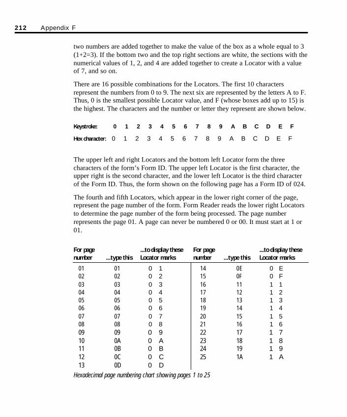
212 Appendix F
two numbers are added together to make the value of the box as a whole equal to 3(1+2=3). If the bottom two and the top right sections are white, the sections with thenumerical values of 1, 2, and 4 are added together to create a Locator with a valueof 7, and so on.
There are 16 possible combinations for the Locators. The first 10 charactersrepresent the numbers from 0 to 9. The next six are represented by the letters A to F.Thus, 0 is the smallest possible Locator value, and F (whose boxes add up to 15) isthe highest. The characters and the number or letter they represent are shown below.
Keystroke: 0 1 2 3 4 5 6 7 8 9 A B C D E F
Hex character: 0 1 2 3 4 5 6 7 8 9 A B C D E F
The upper left and right Locators and the bottom left Locator form the threecharacters of the form’s Form ID. The upper left Locator is the first character, theupper right is the second character, and the lower left Locator is the third characterof the Form ID. Thus, the form shown on the following page has a Form ID of 024.
The fourth and fifth Locators, which appear in the lower right corner of the page,represent the page number of the form. Form Reader reads the lower right Locatorsto determine the page number of the form being processed. The page numberrepresents the page 01. A page can never be numbered 0 or 00. It must start at 1 or01.
For page ...to display these For page ...to display these number ...type this Locator marks number ...type this Locator marks
01 01 0 1 14 0E 0 E02 02 0 2 15 0F 0 F03 03 0 3 16 11 1 104 04 0 4 17 12 1 205 05 0 5 18 13 1 306 06 0 6 19 14 1 407 07 0 7 20 15 1 508 08 0 8 21 16 1 609 09 0 9 22 17 1 710 0A 0 A 23 18 1 811 0B 0 B 24 19 1 912 0C 0 C 25 1A 1 A13 0D 0 D
Hexadecimal page numbering chart showing pages 1 to 25
SO Appendix F Final.qxd 3/21/00 6:12 PM Page 212
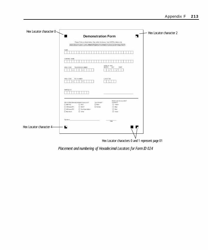
Placement and numbering of Hexadecimal Locators for Form ID 024
Appendix F 213
Hex Locator character 0 Hex Locator character 2
Hex Locator character 4
Hex Locator characters 0 and 1 represent page 01
SO Appendix F Final.qxd 3/21/00 6:12 PM Page 213

214 Appendix F
SO Appendix F Final.qxd 3/21/00 6:12 PM Page 214

215
Glossary
Association ManagerAs forms are created and Published in Form Publisher, or defined using TemplateMaker, they are registered with Scannable Office’s Association Manager. TheAssociation Manager keeps track of each form and its related files in an Access databasethat includes: Form ID, Form (.FRM) file location, Map (.MAP) file location, totalnumber of successful images processed, and comments.
AutoData Document TemplateThe AutoData Document Template contains a series of sophisticated macros that areautomatically embedded in Microsoft Word as Form Publisher powers up. The documenttemplate, named AutoData.DOT, contains such proprietary AutoData elements as the fiveLocator marks, the AutoData Toolbar for quick access to six scannable object types, andspecial AutoData fonts. The AutoData Document Template transforms Microsoft Wordinto a flexible object-based form designer.
AutoData Data MapperAutoData Data Mapper is an advanced module in Scannable Office that automaticallymaps scannable objects on any new or existing form to a Microsoft Access database,Excel spreadsheet, or ODBC data source. Once the form and database relationships areestablished, the form/table/field information can be accessed in an easy-to-view grid.Handy Wizards register new forms and create new databases for the forms.
AutoData Form PublisherAutoData Form Publisher is a flexible object-based design module in Scannable Officethat creates the scannable form. Form Publisher provides the tools to place scannableobjects—such as check marks, hand print boxes, bar codes, OCR fields, image captureand key entry zones—on your form with the click of a button. Many of these scannableelements are pre-defined and formatted for quick form design. When the form design iscomplete, a Publish routine checks the form design and then automatically creates a
Glossary Final.qxd 3/21/00 6:29 PM Page 215
216 Glossary
form template. The result is a scannable form that can now be scanned and read byForm Reader.
AutoData Form ReaderAutoData Form Reader is the module in Scannable Office that scans, processes andverifies the scannable data on forms created in Form Publisher or defined usingTemplate Maker. This module stores the scanned data directly in an Access database,Excel spreadsheet or ODBC data source, thus eliminating cumbersome data exportsteps. Operators can choose to scan, process and verify forms in a single pass; or thesesteps can be handled as separate activities, and at different times.
AutoData Scannable OfficeAutoData Scannable Office is a sophisticated software program that brings automateddata collection to the convenience of the desktop. Scannable Office leverages the powerof Microsoft Office—the most popular business application suite on the market—andtakes advantage of product familiarity to shorten the user’s learning curve. ScannableOffice embeds special AutoData macros in Microsoft Word to transform it into apowerful form design tool. It also relies on Access or Excel as a report generator andinformation management tool. Scannable Office consists of four modules: FormPublisher, Form Reader, Data Mapper and Template Maker.
AutoData Template MakerAutoData Template Maker is the bridge software that enables forms created outside ofScannable Office (e.g., AutoData PRO, PageMaker, QuarkXPress) to be compatible withScannable Office software. Template Maker identifies and defines each scannable field’stype and location on a form. This process then tells Form Reader where to find data onthe form, and what to do with it once it is located. In essence, Template Maker creates ascannable form template that is used by Form Reader. This module is covered in detailin the AutoData Template Maker manual.
Automatic Document Feeder (ADF)An Automatic Document Feeder is a scanner accessory or built-in feature which allowsthe user to feed multiple sheets through the imaging device. Some ADF units supportduplexing (front and back scanning of a sheet in a single pass). AutoData ScannableOffice requires the use of an imaging device with an ADF.
Bar Code FieldA Bar Code Field contains data printed with the ADS Barcode font. This data is read byForm Reader and copied to the appropriate field in the database. ADS Barcode isequivalent to the Barcode 3 of 9 font.
Glossary Final.qxd 3/21/00 6:29 PM Page 216
.BMP FileA .BMP file is an Image file with the .BMP extension (Windows Bitmap format), awidely supported Image file format.
Check Mark FieldA Check Mark Field requires the respondent to choose one or more options from aselection of possible responses by placing a mark or marks in a circle or box. Responsesmay range from a simple “Yes/No” to as many as 30 check mark areas labeled with textor assigned a value. Unlike Optical Mark Read (OMR) scanning technology thatrequires the respondent to completely “fill in the bubble”, AutoData technology canrecognize check marks, hatch marks or partially filled check mark areas.
Confidence LevelThe Confidence level is the user-adjustable threshold (from 1 to 10) at which theAutoData hand print engine questions the contents of a Hand Print Field. When a formis being processed, the engine analyzes the quality of the characters that are handprinted in the Hand Print Field. The default Confidence level is 5.
Database
A database is a collection of data in a database management system (DBMS). Thestructure and format of the data is determined by the DBMS, a layer of softwarebetween the physical database and the user. The DBMS (e.g., Access, Excel,FoxPro, Paradox) manages all access to the database.
Delimited Text FileA delimited text file is an ASCII file containing fields (blocks of data) which may beread, edited and printed by Windows Notepad as well as many word processors and dataprograms. “Delimited” refers to the character used to separate the fields. AutoData FormReader is capable of outputting a database in delimited text file format, with a choice ofdelimiters.
Dialog BoxA dialog box is a window in which you provide information to a program.
.DOC FileThe .DOC extension identifies a Microsoft Word document file.
FieldA field is any scannable object on an AutoData form which contains data to be captureddirectly or as an Image file or by operator entry. A field requires a name, an order in
Glossary 217
Glossary Final.qxd 3/21/00 6:29 PM Page 217
which it is to be read relative to the other fields in the form, and—when completedforms are processed—a designated destination. A field is also used in a database recordto store information.
FormA form is an instrument designed to capture information provided by a respondent usingone or more types of scannable object fields.
Form DefinitionA form definition is a concise description of all scannable objects on a form. Thedefinition includes the type of field, its precise location on the form, and all assignablecharacteristics. This term is used most frequently in Template Maker. As the formdesigner is manually defining each scannable object on the form, this process is referredto as form definition .
Form IDA Form ID identifies each scannable form. A Form ID can be presented in the form ofHexadecimal Locators or bar codes. Although Form IDs are not absolutely required, it ishighly recommended that each scannable form physically contain a Form ID for easyidentification, and that each Form ID is the same as the form name. The 3-digit Form IDappears on the bottom of each scannable form that is Published by Form Publisher.
A form is an instrument designed to capture information provided by a respondent usingone or more types of scannable object fields.
FramesFrames are moveable, resizable areas that surround each individual text box, graphicelement or scannable object. The use of frames for the placement of these objects on aform simplifies movement and alignment.
.FRM FileA Form file is an information file with the .FRM extension created by AutoData FormPublisher during the Publish routine, or generated by Template Maker during the formdefinition process. A .FRM file is also generated by AutoData FORM and is supportedby Scannable Office for backward compatibility (v.4.0 and higher).
This file is stored in the same location as the .DOC file created by Form Publisher (orthe desktop publishing file or other Form file defined by Template Maker). The Formfile is essentially a form template that contains pertinent information on the location andproperties of all scannable objects. This information is used by other Scannable Officeprograms in the processing of completed forms.
218 Glossary
Glossary Final.qxd 3/21/00 6:29 PM Page 218
Hand Print FieldA Hand Print Field contains hand printed text intended for recognition by FormReader’s hand print reading engine. The data—subject to user-determined levels ofverification, validation and operator correction—is saved to a database.
.IFA FileAn Image File Association (.IFA) stores the Image file name and page information inTemplate Maker.
Image Capture FieldAn Image Capture Field contains graphics or handwritten text to be captured and savedas an Image file. An Image Capture Field is delimited by a frame. The two popularapplications of this field type are signatures and comment capture. AutoData FormReader is capable of saving an image in any of three popular formats: .TIF (default),.BMP or .PCX.
Interpret (Read)Interpret refers to the ability of Scannable Office to make sense of (read), and assign ameaning to, that which it “sees” in an image. The scannable object being interpretedmay be any one of six field types used in Scannable Office forms.
ISISISIS stands for Image and Scanner Interface Specification. It is a software interfacedeveloped by Pixel Translations, a division of Input Software. ISIS is a system ofsoftware modules designed to control scanners and printers, assist in the viewing ofimages, compress and convert the format of image data, and read or write filescontaining image data with a high degree of accuracy and precision. ISIS drivers areavailable for many scanners. The Pixtran website at www.pixtran.com has lists ofscanners for which ISIS drivers are available.
Key Entry FieldA Key Entry Field contains handwritten text which must be read and interpreted by anoperator who then makes an appropriate typed entry that is saved to the database. A KeyEntry Field area is delimited by a box within a frame.
LocatorsLocators define the four corners of a form page. Older AutoData programs used simplethin line corner marks. Newer AutoData programs such as Form Publisher employ moresophisticated hexadecimal marks which carry both form identification and pagenumbering information. In addition, Locators can help Form Reader to digitallystraighten out a form that has twisted slightly while being scanned.
Glossary 219
Glossary Final.qxd 3/21/00 6:29 PM Page 219
.MAP FileA Map File (.MAP) is an Access database created by Data Mapper. The file containsinformation on all the scannable objects on a form and the database which will hold thescanned data.
Menu BarA menu bar is a Windows program interface which typically appears just below theprogram title bar. It contains key words such as File, Edit, View, and Help. Clicking onany of these menu bar words produces a drop-down menu with additional choices.Alternatively, the user may access these drop-down menus by holding down the ALTkey and clicking on the first letter of the menu bar name (e.g., the File menu may beopened by the key combination ALT+F).
ODBC Data SourceODBC stands for Open Database Connectivity, a specification for an ApplicationProgramming Interface (API) that defines a standard set of routines with which anapplication can access data in a data source. The data source is the data a user wants toaccess, its associated operating system (DBMS), and the network platform (if any).
OCR FieldAn OCR Field contains machine-printed text intended for recognition by Form Reader’sOCR reading engine. The most common OCR application is numbers or letters used as aunique form identifier. Examples would include a serial number (e.g ., 049785), alocation (e.g. , WEST SITE), an individual’s name (e.g. , DR JONES), or any othercharacteristic that is unique. For optimum recognition, AutoData recommends usingeither Arial or Times New Roman fonts in 18 points.
.PCX FileImage files ending in .PCX are in the Zsoft Paintbrush format, a widely supported imagefile format.
Processing (or Reading) EngineThe processing (or reading) engine is the core component of AutoData Form Reader. Aseries of highly specialized engines—a check mark (OMR) engine, hand print (ICR)engine, bar code engine, and OCR engine—each searches for and analyzes all scannableobjects on a form, extracts data, and places the appropriate data in the final database.
PublishPublish is a proprietary AutoData routine in Form Publisher that runs a series ofspecification checks on your form to ensure it complies with some basic scannable formrequirements, then automatically creates the Form template (.FRM) file with the click of
220 Glossary
Glossary Final.qxd 3/21/00 6:29 PM Page 220
a button. A correctly Published form allows the Form Reader module to recognize aform’s scannable objects and extract the information filled in by respondents.
.RST FileThe .RST file is created by the Publish function in Form Publisher or by the formdefinition process in Template Maker. This file contains all the information needed byForm Reader to precisely locate and interpret the scannable objects on a form.
Scannable ObjectA scannable object is any field on a form containing information or data that is created,scanned, and recognized by AutoData Scannable Office software and an input sourcedevice such as an imaging scanner. There are six scannable object types: check marks,hand print, bar codes, OCR, image capture and key entry zones.
ScannerA scanner is any flatbed or sheet-fed device capable of capturing an image in digitalform. Control of the scanner, transfer of the digital image to the computer, and renderingthat image in a format recognizable by installed system software is the function of thesoftware interface. The two most popular interface protocols are ISIS (preferred) andTWAIN. In order to operate correctly, AutoData software applications require animaging scanner with an automatic document feeder (ADF).
Serial FieldA Serial Field appears on every page of a multi-page form. The data must be identicalon each page of the same multi-page form. The data must be different for each multi-page form but the format must be the same. An ideal example of a Serial Field would bea social security number which has the same format for all respondents but specificcontent which varies from person to person. A good example of a computer-generatedserial field would be a product serial number, provided it conforms to a consistentformat.
SmartMemory™
AutoData’s patented SmartMemory technology is the processing engine for recog-nizing hand printed characters. Unique features of SmartMemory enable high recog-nition rates, and the unique ability to improve recognition over time by adapting tothe specific hand print styles of form respondents.
Text FileA Text file is an ASCII file which may be read, edited and printed by Windows Notepadas well as most word processors. AutoData programs make use of Text files for a varietyof reports. See Delimited Text files.
Glossary 221
Glossary Final.qxd 3/21/00 6:29 PM Page 221
.TIF FileImage files with a .TIF extension are in the Tagged Image File format, a widelysupported image file format. Scannable Office recognizes and generates .TIF files as thedefault Image file type.
ToolbarThe toolbar contains a series of program-specific buttons. Clicking the button launches aprogram feature. These buttons provide shortcuts to functions which can also belaunched by menu commands. Most toolbars may be turned into “floating” or moveabletoolbars by double-clicking on the toolbar’s left margin, or by simply dragging themdown into the workspace. The floating toolbar can be restored to its usual place bydragging it back or by double-clicking on its title bar.
TWAINTWAIN is a software protocol and application programming interface forcommunication between software and image acquisition devices such as scanners anddigital cameras. Use of the TWAIN driver requires the operator to manually accept eachpage as it is fed through by the scanner’s ADF. For this reason, an ISIS-compliantscanner is the recommended scanner of choice.
ValidationValidation determines if data entered in a field is valid, i.e., conforms to what is apossible and acceptable entry in the given field. In Form Reader, Time, Date and Statefields are checked by the software against predetermined rules or guidelines.
VerificationVerification establishes accuracy of captured data. Verification options in ScannableOffice vary with the type of field. Program settings determine the level of operatorintervention and the level of trust placed in the program’s ability to read data correctly.
WizardA Wizard is a tool that walks a user through the steps of a complex task in an easy-to-follow manner. It typically performs calculations or routines “behind the scenes” afterthe user has answered some basic questions. Scannable Office has two built-in Wizards.The Registration Wizard registers a scannable Form ID in a database, and the DatabaseWizard automatically creates a new database or spreadsheet to which a form’s data willbe directed.
222 Glossary
Glossary Final.qxd 3/21/00 6:29 PM Page 222

Index.BMP 83, 217.DOC 22.DOC file 217.FRM 22.FRM (Form) file creation 93.FRM file 218.IFA 22.IFA file 219.MAP 22.MDB 22.PCX 83.PCX file 220.RPT 22.RST 22.RST file 221.TIF 83, 169-171.TIF file 22211"×17" duplex booklets
printing 187scanning 1
AAbout Data Mapper
button 141command 143
About Form Reader 103the Verification Window 124
About Form Reader button 100Accept Low Confidence Characters 112Access 2000 121, 147Access 97 121, 147Access command 101Add Page button 38ADS Barcode font 27Advanced Topics 165-188Align Bottom button 39Align Center button 39Align Left button 39Align Right button 39Aligning elements on form 88-89Alpha Lowercase 80Alpha Only 67, 80Alpha Uppercase 80
Alpha Value (A-Z) 55adding custom labels to 61-62Multiple Marks Allowed 58-60Treat as One Field 59
Alphanumeric 67, 80Association database 116
default name and path of 159identifying Map file in, for Form ID 123identifying target database or spreadsheet file in 123modifying fields in 160-163overview 158-163registering Form ID in 116, 118-120, 123, 151
Association Database command 142Association Manager 215. See also Association database
adding Form (.FRM) files to 160-161adding Map files to 161default name and path of 159deleting entries in 161-162exiting 163opening 160overview of 158-163structure of 204widening columns in 162window elements 159-160
Associative recall 207-209AutoData Data Mapper 11-12, 139-163, 215. See alsoData Mapper
keyboard shortcut commands 156window description of 144
AutoData Document Template 215AutoData Form Publisher 10, 35-95, 215. See also FormPublisher
launching 36-37window description of 37-40
AutoData Form Reader 11, 216. See also Form Readerlaunching 98-99window description of 99-103
AutoData Scannable Office 216applications and uses for 23number of pages 29
AutoData SmartMemoryand associative recall 207-209Computer Memory 209
Index 223
SO Index Final.qxd 3/21/00 6:29 PM Page 223
Disabled 113Hard Train 113Low Confidence 209Low Level Feature Sensing 209operational diagram 208origin of 207Recognized Character 209Save Trained Characters on Exit 113-114SmartMemory software 209Soft Train 113Training options 209
Hard Train 209Soft Train 209
Unknown Shapes 209AutoData Template Maker 12, 216AutoData Toolbar 37-39AutoData.DOT 91Automap
running after Database Wizard 151-152running from toolbar 152-153
Automap command 143Automatic Document Feeder (ADF) 216
BBar Code Field button 38Bar Code Field(s) 216
as Form ID 76, 123as Serial Fields 76creating 75-76creating place holders for labels 77-79guidelines for 76in other AutoData software versions 27merging serialized data to 181-186uses for 74-75verifying 130vs. OCR Fields 79
Barcode 3 of 9 27Batch command 102Batch Mode processing option 111Batch Process button 100Batch processing 114-115, 165-168
processing flowchart 168using imported images 170using PaperPort 173vs. Interactive processing 114-115
Batch Scan button 100Bring to Front button 38Bringing element to front 88
CCapture Only if Data Present 84Change Document Type 182Character Training 209Check Mark Field button 38Check Mark Field(s) 54-66, 217
adding custom labels to 60-62and Treat as One Field option 59, 64-65and Verify if No Selection 60, 65creating 54-60maximum boxes or circles 26multiple marks 26Multiple Marks Allowed 57-59read order for 57, 64removing boxes or circles from 65resizing check mark grid 65-66resizing frames of 51response types 54-56single mark 26specifying number of boxes or circles 56-57, 64specifying style of boxes or circles 57, 64User Defined Labels 26, 56, 62-65verifying 127-128
City 67Close command 101Comments field 159Company Name 67Confidence level 70-71, 217
Accept Low Confidence Characters 112Enable Strict Field Validation 112Replace Low Confidence Characters With 112
Confidence level tradeoff chart 71Contents and Index command 103, 136, 143Context Help 103, 134, 141
button 100, 141command 136, 143
Convert, Word document to scannable form 90-91Create Form Letters 182Create New Database command 143
DData Mapper 117
overview of 11-12Data Mapper Window
Field View 144Form View 144Map View 144
224 Index
SO Index Final.qxd 3/21/00 6:29 PM Page 224

Status Bar 144Table View 144
Data text box 126Database 217Database Wizard 117, 120-122
placing data in a single table 121, 147placing data in multiple tables 121, 147using to create new database in Data Mapper 147-148
Database(s) and spreadsheet(s)choosing file name for 148creating with Database Wizard 147-148
Form (.FRM) file created in Form Publisher 150Form (.FRM) file created in Template Maker 50
identifying during Database Wizard 116mapping manually 153-156mapping to single vs. multiple tables 155placing data in a single table 121, 147placing data in multiple tables 121, 147selecting or creating, in Data Mapper 146types 121, 147using Data Mapper 117using Database Wizard 117, 120-122writing form data to an existing database 117, 149
Form (.FRM) file created in Form Publisher 150Form (.FRM) file created in Template Maker 50
Date (DD/MM/YYYY) 67Date (MM/DD/YYYY) 67Date (YYYY/MM/DD) 67Decimal (N.DD) 67Delete
Map file fields 156-157scannable objects 51
Delete Images After Processing 165Delete Images After Processing option 111Delimited Text File 217Demo.DOC 7Demo.RST 7Descriptive text 51Dialog Box 217Disabled 113Distribute Horizontally button 39Distribute Vertically button 39Distributing elements horizontally 89Distributing elements vertically 89Down, Then Right read order 57, 64Duplex booklets and forms 31-32, 187-188. See also11"×17" duplex booklets
number of pages 32
page numbers on 187paper weight for 31printing 187
EEdit Association Database button 141Edit menu
Data Mapper 142Editing Published files 45-49Element
bringing to front 88sending to back 88
Enable Duplex Mode 107, 196Enable Scan Ahead 107, 196Enable Strict Field Validation 112, 129Entire Database 152Excel 121, 147Excel command 101Exit command 102, 134, 142Export Table to Text File
button 100command 101
Exporting to a text file 180
FFax 108-109
Delete Images after Processing 111Fax
processing 175-179processing flowchart 179
FAX command 102Field 217Field Attributes, for Hand Print Fields 71-72Field Formats, OCR Fields 80Field Names
and Automap 153defined 50reserved, and ODBC data sources 50
Field Orderdefined 50
Field template, for User Defined Hand Print Fields 73-74Field Types, for Hand Print Fields 67-69
summary of characteristics 69Field View on Data Mapper Window 144File menu
Data Mapper 141-143Form Reader 101-102
Index 225
SO Index Final.qxd 3/21/00 6:29 PM Page 225

Image Viewer 134First command 136Fixed Length 72Folded forms 32-33Fonts, changing for OCR Field text 81-82Form 218Form (.FRM) file
adding or changing in Association Manager 160-161created in Template Maker 150creation of, during Publishing 93mapping to existing database or spreadsheet 150naming 146selecting for Map file 145-146
Form Definition 218Form fields
mapping to database fields manually 154-156mapping to database fields with Automap 148, 149-157
Form File field 159Form ID 218
and Lock Form option 118character limits for each type 160identifying Bar Code Field Form IDs duringprocessing 123identifying during processing 123identifying during scanning session 116naming 146registering in Association database 116
Form ID field 159Form ID process option 110Form ID(s)
and Bar Code Fields 76assignment of during Publish routine 94
Form Publisheroverview of 10
Form Readeroverview of 11
FormRules.DOC 6, 42Forms
acceptable ink types 31adding pages to 53designing 23-33distributing elements horizontally on 89distributing elements vertically on 89duplex 31-32field types on 25-29folded 32-33grouping and ungrouping elements on 86-87
layering elements on 88non-reproducible blue ink 31placing text and images on 51-53positioning elements on 88-90printing 32printing after Publishing 94-95processing 104-132. See also Processing Formsproofing prior to Publishing 91Publishing 91-95Publishing vs. printing forms 92rules for placing objects on 41saving 47stapled 33viewing text boundaries on 42
Form View 144Frames 218
resizing 51
GGraphics, selecting format for Image Capture Fields 83Group button 38Grouping form elements 86-87
HHand Print Field button 38Hand Print Field(s) 219
and Serial Field(s) 71-72and Verify Field Always option 72and Verify Field if Data Present option 72and Verify if Low Confidence option 72assigning Confidence level of 70-71data correction methods for 128Field Attributes for 71-72Fixed Length 72guidelines for creating 25-26maximum number of characters 25resizing frames of 51User Defined 26, 73-74verifying 128-130
Hand print sample 43-44, 70Hard Train 113, 209Help menu
Data Mapper 143Form Reader 103Image Viewer 136
Hexadecimal charactersuse of 30
226 Index
SO Index Final.qxd 3/21/00 6:29 PM Page 226

Hexadecimal Locators 211-213keyboard equivalents for 212placement and numbering of 213purpose 211values assigned to sections 211-212
IIdentifying Form ID during scanning session 116Image Capture Field button 38Image Capture Field(s) 219
Capture Only if Data Present 84creating 82-84resizing frames of 51selecting graphics format for 83size and positioning of 84specifying base name for files 83uses for 28, 82verifying 131
Image Database 204-206Image Index field 159Image Information command 135Image Viewer
and scanner brightness settings 137button 100command 103inverting images in 134launching 133opening files in 133printing images in 133rotating images in 133saving files in 133viewing next and previous pages in 134
Images, importing 169-171processing flowchart 171specifying as input source 109-110
Images.MDB 167, 170, 204Import Images
button 100command 101
Input sourcecommand 105Fax 108-109imported images 109-110ISIS-compliant scanners 105-107page orientation 105PaperPort 109specifying 105-109
for networked systems 105
TWAIN-compliant scanners 107-108InstallShield Wizard 4, 193Integer 1-30 (Mult Mark = 1 or 0) 54-55
adding custom labels to 61-62Multiple Marks Allowed 57-59Treat as One Field 59
Interactive command 102Interactive processing 114-115
vs. Batch processing 114-115Interpret 219Invert command 136Invert Image 134ISIS 219ISIS command 102ISIS-compliant scanners
changing settings for 106-107changing setup information for 106configuring 106Delete Images after Processing 111Enable Duplex Mode 107Enable Scan Ahead 107installing new drivers for 194processing flow 197setting up 193-197
adjusting settings 195configuring 193-196recommended settings for 195setting scanning area 196
specifying as input source 105-107
KKey Entry Field button 38Key Entry Field(s) 219
adding text labels to 85and Serial Fields 85creating 85-86resizing frames of 51uses for 28, 84Verify Only if Data Present 85verifying 132
LLabels
adding custom, to Check Mark Fields 60-62custom vs. User Defined 62
Landscape orientation 114Last command 136
Index 227
SO Index Final.qxd 3/21/00 6:29 PM Page 227
LaunchingData Mapper 140Form Publisher 36-37Form Reader 99Image Viewer 133
Locators 39-41, 211-213, 219distance from, for form objects 41identifying during processing 123old style vs. new style marks 110on 11"×17" duplex booklets 187use of 30
Lock Form 118Low confidence 209
Accept Low Confidence Characters 112Verify Low Confidence Characters 111-112
Low Level Feature Sensing 209
MMail Merge 181Make Place Holder Field 76
creating 77-79Make Serial Field 80, 85, 184Male or Female 56Map (.MAP) File 220Map (.MAP) files 123
adding blank row in 157adding or changing in Association Manager 161copying, deleting, moving fields in 156-157creating 145-158
manually 153-156preparation prior to creating 149-150with Automap 151-153
opening 140saving 158selecting Form (.FRM) file for 145-146structure of 206
Map File field 159Map View 144, 154Mapper command 103Mark as Unread 176Menu Bar 220Merged field forms, printing 94-95Merging serialized data
to a Bar Code Field 181-186to an OCR Field 186
MRU command 102, 134, 142Multiple Marks Allowed 57-59, 64Multiple-page forms and documents 114
and Bar Code Fields 76and Serial Fields 71specifying number of tables for, in database 121
NNetworked environments
installing Scannable Office in 189-191logging on 189specifying file location 190specifying network server 190
Save Trained Characters on Exit 113New
button 140command 141
Next command 136Next Page 134None command 102Non-reproducible blue ink 31Numeric (0-9, $ + - % / =) 80Numeric Only 67, 80
OOCR Field button 38OCR Field(s) 220
and Serial Fields 80changing text font characteristics of 81-82creating 79-81field formats for 80field size, limit on 80fonts for 27merging serialized data to 181-186uses for 79using with Word’s merge feature 80Verify Always 81verifying 131vs. Bar Code Fields 79
ODBC command 101ODBC data source 220
reserved Field Names 50One For Each Page 121Open
button 140command 101, 134, 141
Open Access Database button 99, 141Open Data Source 182Open Database command 142Open Excel spreadsheet button 99, 141
228 Index
SO Index Final.qxd 3/21/00 6:29 PM Page 228

Open Image File button 133Open ODBC Data Source button 99, 141Opening existing files
Published files 45-46unpublished forms 45
Options command 103
PPage
number of 29order of 29orientation 30orientation, changing 40-41size requirements 29-30size, changing 40-41
Page menuImage Viewer 136
PaperPortspecifying as input source 109-110
PaperPort processing 172-174processing flowchart 174
Personal Name 67Phone Number 67Place holders, for bar code labels 76
creating 77-78specifying an exact size for 78
Portrait orientation 114Positioning Tool button 133Previous command 136Previous Page 134Print command 134Print Current Image button 133Print Setup command 134Printing forms 32, 93
and Locators 30merged field forms 94-95, 185reproduction masters 94
Prior to Publishing 91-92data management 92proofing 91
Process menuForm Reader 102
Process optionsBatch Mode 111Form ID 110setting 110-111
Process tab 110-111Processing (or Reading) Engine 220
Processing forms 122-133deleting images after processing 111Images.MDB 173in Batch mode 165-168in Interactive mode 114-122, 122-133steps taken during, by Form Reader 123using imported images 169-171using PaperPort 172-174using WinFax PRO 175-179
Publish 220Publish button 38Publishing forms
.FRM file creation 93editing Published forms 45-46prior to Publishing
data management 92proofing 91
status of process 92vs. printing forms 92
RRead option 176Read order
of Check Mark Fields 64Recognize All Characters 80Recognize New Style Locators 110Recognized Character 209Registration Wizard 119-120Regroup button 38Regrouping form elements 87Replace Low Confidence Characters With 112Reproduction Masters 94Re-Publish
after editing form 46Response types, for Check Mark Fields 54-56Right, then Down read order 57, 64Rotate Clockwise button 134Rotate Counterclockwise button 133Rotate Left command 136Rotate Right command 136
SSample forms
demo.DOC 7Demo.RST 7demo1.DOC 6FORM RULES (FormRules.DOC) 6
Index 229
SO Index Final.qxd 3/21/00 6:29 PM Page 229

Save As command 134, 142Save command 134, 142Save Current Image button 133Save Trained Characters on Exit 113Saving files
in AutoData Form Publisher 47Scan and Process Forms button 100Scannable Object 221Scannable objects
changes to, after Publishing 46creating, overview of 47-53defining 47-95deleting 51editing properties of 49Field Names for 50Field Order 50resizing frames of 51
Scannable OfficeAutoData Protection Key 5-6file types 203-206file types created by 22installing 4-5
on networks 189-191sample forms provided with 6-7system requirements for
hardware 3-4software 4
Scanner 221effect of brightness settings on images 137ISIS-compliant. See ISIS-compliant scannerTWAIN-compliant. See TWAIN-compliant scanner
Scanning forms 114-122duplex booklets 188exporting data to a text file 180guidelines for 114in Batch mode 165-168mapping to a database 116multi-page forms 114registering Form ID in Association database 116,118-120Serial Fields 114
Selected Table 152Send to Back button 38Sending element to Back 88Serial Field 221Serial Field(s) 114, 166
and Bar Code Fields 76, 181-186and Key Entry Fields 85
and merging 181-186and Microsoft Excel 180and multiple page documents 71and OCR Fields 80, 186and spreadsheets, limits of 72defined 28, 71-72use of 28-29
SmartMemory 113, 221. See also AutoData SmartMemorySmartMemory Software 209Social Security Number 68Soft Train 113, 209Spacing elements on form 89-91Stapled forms 33State 68Status bar command 102, 135, 142Stay On Top command 135Street Address 68
guidelines for, on Hand Print Fields 68
TTable List button 100Table View 144Template Maker
overview of 12Templates and Add-Ins 90Text Boundaries 42-43Text button 38Text File 221Text Label frames 52Time (HH:MM:SS) 12 hour format 68Time (HH:MM:SS) 24 hour format 68Toolbar 222
AutoData Form Publisher 37-39Data Mapper 140-141Form Reader 99-100Image Viewer 133-134
Toolbar command 102, 135, 142Tools menu
Data Mapper 142-143Form Reader 103
Training optionsDisabled 113Hard Train 113Save Trained Characters on Exit 113setting 112-113Soft Train 113
Training tab 112Treat as One Field option 59, 64-65
230 Index
SO Index Final.qxd 3/21/00 6:29 PM Page 230

True or False 55True or False or Other (T/F/O) 55TWAIN 222TWAIN command 102TWAIN-compliant scanner 107-108
configuring 108Delete Images after Processing 111specifying as input source 107-108
TWAIN-compliant scannersconfiguring 199-200processing flow 201recommended settings for 200scanning with 200
Type styles, use of in Form Publisher 41
UUndo Distribute Object 90Undo, Microsoft vs. AutoData 90Ungroup button 38Ungrouping form elements 87Unknown Shapes 209Use Form ID dialog box 116-117User Defined Hand Print Fields
creating 73-74defining field template for 73-74
User Defined Labels 56adding labels 63changing on User Defined Labels tab 63clearing labels 63creating 62-65Multiple Marks Allowed 57-59specifying number of boxes or circles 64specifying style of boxes or circles 64Treat as One Field 59, 64-65Verify if No Selection 65
User Defined Type 68
VValidation 222Verification 222Verification options
setting 111-112validation 112verification 111-112
Verification tab 111-112Verification Window 124-127
command buttons in 126-127
elements in 125-127moving from field to field in 125Status area 125-126Stop on LC Characters 126, 129zooming in and out on 129
Verify Always 81, 123Verify Field Always 72Verify Field if Data Present option 72Verify if Low Confidence 72Verify if No Selection 60, 65Verify Low Confidence Characters 111-112Verify Only if Data Present 85Verifying form data 122-133
Bar Code Fields 130Check Mark Fields 127-128correcting in Data text box 126Enable Strict Field Validation 129Hand Print Fields 128-130Image Capture Fields 131Key Entry Fields 132OCR Fields 131Stop On LC Characters 126, 129Verification Window 124-127
View menuData Mapper 142Form Reader 102Image Viewer 135
Visible Text 77
WWinFax PRO
specifying Fax as input source 108-109WinFax PRO processing 175-179
processing flowchart 179Wizard 222
YYes or No (Y/N) 55Yes or No or Other (Y/N/O) 55
ZZip Code 68Zoom In button 133Zoom Out button 133Zoom To button 133
Index 231
SO Index Final.qxd 3/21/00 6:29 PM Page 231

232 Index
SO Index Final.qxd 3/21/00 6:29 PM Page 232