Embed Size (px)
Citation preview


STIEBEL ELTRON 3
General informationThe chapter Operation is intended for users and quali�ed installers.The chapter Installation is intended for quali�ed installers.
Read these instruction carefully before using the appliance and retain them for future reference. If the appliance is passed on the third party please hand these instructions to the new user.
- This appliance is not intended for use by persons (including children) with reduced physical, sensory or men-tal capabilities, or lack of experi-ence and knowledge, unless they have been given supervision or instruction concerning use of the appliance by a person responsible for their safety.
- Children should be supervised to ensure that they do not play with the appliance.
a
cb d
f e Fig 1
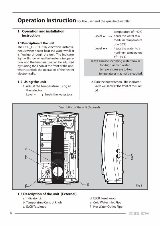
Description of the unit (External)
STIEBEL ELTRON4
Operation Instruction
1. Operation and installation instruction
1.1 Description of the unit.The DHC_EC / EL fully electronic instanta-neous water heater heat the water while it
light will show when the heater is in opera-tion, and the temperature can be adjusted by turning the knob at the front of the unit, which controls the operation of the heater electronically.
1.2 Using the unit 1. Adjust the temperature using at the selector. Level heats the water to a
temperature of~ 40 C Level heats the water to a medium temperature of ~ 50 C Level heats the water to a maximum temperature of ~ 60 C Note : too high or cold water temperatures are to low temperatures may not be reached.
2. Turn the hot water on. The indicator valve will show at the front of the unit (a)
1.3 Description of the unit (External)bonk teseR BCLE .d thgiL rotacidnI .a
b. Temperature Control knob e. Cold Water Inlet PipeepiP teltuO retaW toH .f bonk tseT BCLE .c

ELCB Knob Positioning
Fig 2
STIEBEL ELTRON 5
Operation Instruction
The DHC EC water heater unit is to be installed in a closed, frost-free room (disconnected units are to be stored in a frost-free location, since there will always be some water left in the unit) The water heater is to be installed vertically on a wall (water connection downwards).
Warning : For electrical heating appliances
does not reset automatically, if you would like to reset the unit, the mains power
1.4 This model features an Earth Leakage Circuit Breaker (ELCB) (Type EC only), which should be test a monthly. How to use the ELCB: Before operating the water heater. Turn the ELCB Reset knob (d) at the side of the heater to start operation.How to test the ELCB:Turn the ELCB Test knob (c) at the side of the unit. ELCB Reset (d) will cease to function. Please note that the indicator light at the
ELCB Reset knob (d) to start operate again.
Warning ! If the unit does not operate, even pressing the Reset knob, contact Stiebelservice for a check and repair.
device that functions when the water temperature is unusually high.
In the event that the thermostat
refrain from taking any action. Please contact the Stiebel Eltron Service Center for further inspections and repairs to be made.

STIEBEL ELTRON6
Operation Instruction
2. First Operation
by an expert technician only.
Before turning on the water heater to start operation, turn
tion, and open all of water valves fully at
through the heater and expel air from the
constant. Please ensure that the water heater is functioning correctly, and close the valve again.
- Turn the ELCB Reset knob to the “on” position to start operating the water heater.
WARNING: When selecting an appropriatewater temperature, the temperature may be dangerously high, especially for children. Keep away from the hot water outlet, as it may cause a potential scalding hazard.
- The indicator light will show. - The DHC_EC Water Heater features a temperature control knob at the front of the unit, whereby 3 temperature levels may be selected.
2.1 Adjusting Water Flow If the required temperature is not
turning the combination valve or water
The hot water temperature depends on the power of the unit, the cold water temperature and the

STIEBEL ELTRON 7
Operation Instruction
3. Technical Data
LE 01 CE 8 LE 8 CE 6 LE 6 epyT
Norminal capacity l. 0.45 0.50
teltuo esolC ngiseD
aPM 0.1 / rab 01 erusserp retaw .xaM
Min. water pressure to activate unit 0.2 bar / 0.02 MPa
)daerhT lanretxE( “½ G noitcennoc retaW
Dimension (W x H x D) mm. 360 x 200 x 110
0.2 .gk thgieW
.V 042..022 CA/EP/N/1 noitcennoc lacirtcelE
Recomended circuit breaker A. 32 40 50
Recomended cable size Squmm) 4-6 6-8 8-10
Rated power (kW) Rated current (A.) Kw - A kW - A kW - A
9.9 4.63 - 0.8 3.72 - 0.6 V 022
8.73 - 7.8 7.82 - 6.6 V 032
6.93 - 5.9 6.92 - 1.7 V 042
- BCLE - BCLE - ecived ytefaS
4. Regulations and Provisions - Regulations of the local power supply company should be observed. - Regulations of the water supply company should be observed - Read & study the technical data. - Install the unit vertically on the wall. - Electrical connection to be secured.
The device must be capable of being isolated from the mains, for example by fuses, with an isolating distance of at least 3.5 mm. in all poles.
5. Important notes - Make sure the data on the unit rating plate is current
the wall - Material for the water installation: Steel, copper, or plastic piping systems. If plastic piping systems are being used, the following instructions are to be respected. - Temperature : max 60 ˚C - Pressure : max 10 bar
The unit must be connected to the protective earth conductor (see electric circuit diagram).
STIEBEL ELTRON8
Operation Instruction
Guarantee
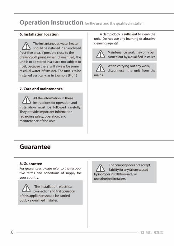
6. Installation location The instantaneous water heater should be installed in an enclosedfrost-free area, if possible close to the
unit is to be stored in a place not subject to frost, because there will always be some residual water left inside). The unit is to be installed vertically, as in Example (Fig 1)
7. Care and maintenance
All the information in these instructions for operation and installation must be followed carefully. They provide important information regarding safety, operation, and maintenance of the unit.
unit. Do not use any foaming or abrasive cleaning agents! Maintenance work may only be
When carrying out any work, disconnect the unit from the mains.
8. GuaranteeFor guarantees please refer to the respec-tive terms and conditions of supply for your country.
The installation, electrical
of this appliance should be carried
The company does not accept liability for any failure caused by inproper installation and / or unauthorized installers.
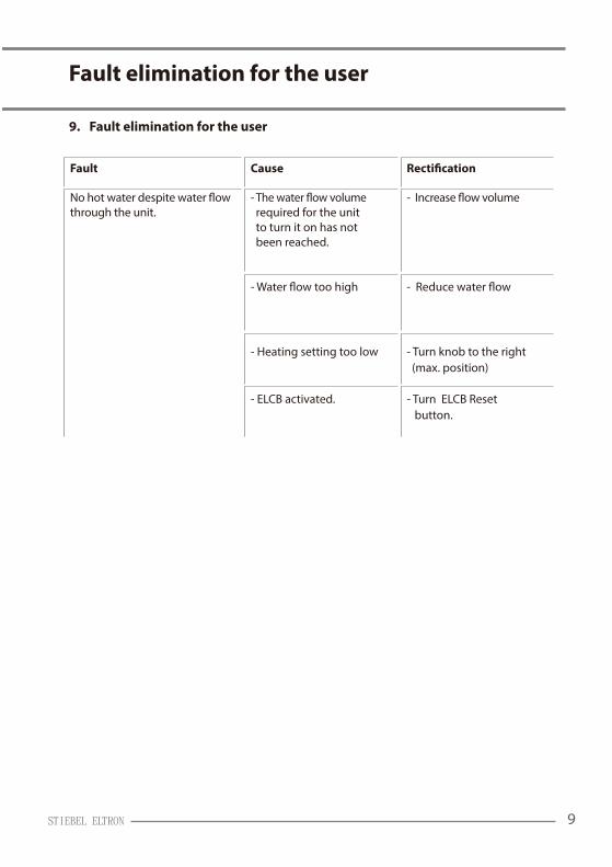
9. Fault elimination for the user
STIEBEL ELTRON 9
Fault elimination for the user
through the unit.
required for the unit to turn it on has not been reached.
- Heating setting too low - Turn knob to the right (max. position)
- ELCB activated. - Turn ELCB Reset button.

STIEBEL ELTRON10
Installation Instruction
Description of the unit (Internal)
16
16
5
2 13
11
12
14
7
8
9
10
15
17
Fig 3
Description of the unit (internal) 1. Upper mounting hole 2. Lower mounting hole 3. Depth for mounting screw (Fig 7#3) 4. Distance of the connection cable (Fig 6#4) 5. Thermostat 6. Cable entry with seal
7. Electrical connection 8. ELCB (option) 9. Plug connecting the circuit board to the cover 10. Reed switch 11. ELCB Test (option) 12. ELCB Reset (option)
13. Cold water connection 14. Hot water connection 15. Flow Limiter 16. Circuit board cover 17. Cover

Fig 4
Installation to a bath / sink.
Fig 5 Fig 6
elbaCnoisnemiD
4
100 mm
200 mm35 mm
G1/2
G1/
2
110 mm.
59 m
m.
280
mm
.
360
mm
.27
0 m
m.
264
mm
.
9 m
m.
50 m
m.
65 mm
STIEBEL ELTRON 11
Installation Instruction

Fig 7 Fig 8
Using the installation template to drill the holes Wiring diagram
Wall Mounting
A - Heating ElementB - Electronic control setC - Control Triac setD - Thermal cut-outE - Temperature Sensor (Inlet)F - Temperature Sensor (Outlet)G - ELCB (option)
4 x 35 mm
4,3 mm
Fig 9
min. 4.5 mmmax. 5.5 mm
mm 6
4 x 35 mm
6 mm
4 x 35 mm
6 mm
3
STIEBEL ELTRON12
Installation Instruction

Fig 10 Fig 12
Fig 11 Fig 13
(concealed connection)
STIEBEL ELTRON 13
Installation Instruction
InstallationPreparation before installation of the unit: - Before taking any action, always
- Place a drilling guide at the drilling position in order to drill a hole in the wall (Fig 7). - Insert a wall plug and screw in (the depth of the protruding screw head must be correct) (Fig 7#3).
- Remove the screw from underneath the water heater to open the cover of the unit.
.
- Open the cover of the unit. - Remove the plug connecting the cover of the unit. - Inspect the internal components.The cable must be in good condition, and
position.
- Create an opening for the water inlet in the case of wall-embeded and wall-mounted pipes.
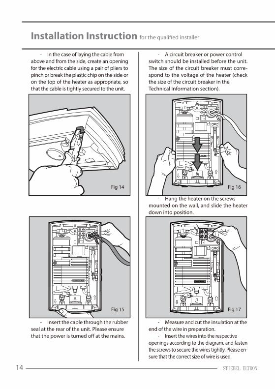
Fig 15
Fig 16
Fig 17
Fig 14
STIEBEL ELTRON14
Installation Instruction
- In the case of laying the cable from above and from the side, create an opening for the electric cable using a pair of pliers to pinch or break the plastic chip on the side or on the top of the heater as appropriate, so that the cable is tightly secured to the unit.
- Insert the cable through the rubber seal at the rear of the unit. Please ensure
- A circuit breaker or power control switch should be installed before the unit. The size of the circuit breaker must corre-spond to the voltage of the heater (check the size of the circuit breaker in the Technical Information section).
- Hang the heater on the screws mounted on the wall, and slide the heater down into position.
- Measure and cut the insulation at theend of the wire in preparation. - Insert the wires into the respective openings according to the diagram, and fasten the screws to secure the wires tightly. Please en-sure that the correct size of wire is used.

A
min. 46max. 50mm
WWC
B
KW
KW
BA
91 giF81 giF
STIEBEL ELTRON 15
Installation Instruction
Connecting Water Pipes (concealed connection)Connecting the water heater to a wall-em-bedded water pipe: - Connect the nipple joints (Fig 18/B) to the cold water inlet pipe and the hot water outlet pipe embedded in the wall at an appropriate position and depth (please pay attention to the distances shown in the dia-gram).
- Screw the joints on the unit (Fig 18/A) to the joints (both hot and cold water), using a rubber leakage gasket (Fig 18/C) between the joints.
Installing Water Heater wall-mountedConnecting the water heater to a wall-mounted water pipe: - Connect the prepared water pipe to the pre-assembled nipple joint. - Screw the joints on the unit (Fig 19/A) to the pipe (both hot and cold water), using a rubber leakage gasket (Fig 16/B) between the joints.
The cold water pipe must be turned on in order to rinse it before installation. Pressure-resistant equipment must be used in compliance with accepted standards.

Fig 20
Fig 21
Fig 22
STIEBEL ELTRON16
Installation Instruction
- Install the cover. Connect the power cord between the circuit board and the cover.
- After installation is complete, close the casing and screw in tightly.