Embed Size (px)
Citation preview
Installation instructionsfor contractors
VIESMANN
Vitoligno 300-PType VL3BPellet boiler
VITOLIGNO 300-P
5443 451 GB 4/2013 Dispose after installation.
2
Please follow these safety instructions closely to prevent accidents and mate-rial losses.
Safety instructions explained
DangerThis symbol warns against therisk of injury.
! Please noteThis symbol warns against therisk of material losses and envi-ronmental pollution.
NoteDetails identified by the word "Note" con-tain additional information.
Target group
These instructions are exclusively inten-ded for qualified contractors.■ Work on gas installations must only be
carried out by a registered gas fitter.■ Work on electrical equipment must
only be carried out by a qualified elec-trician.
Regulations
Observe the following when working onthis system:■ Statutory regulations regarding the
prevention of accidents■ Statutory regulations regarding envi-
ronmental protection
■ The Code of Practice of relevant tradeassociations
■ all current safety regulations asdefined by DIN, EN, DVGW, TRGI,TRF, VDE [and all local standards].a ÖNORM, EN, ÖVGW-TR Gas,
ÖVGW-TRF and ÖVEc SEV, SUVA, SVGW, SVTI,
SWKI, VKF and EKAS guideline1942: LPG, part 2
Working on the system
■ Isolate the system from the power sup-ply (e.g. by removing the separate fuseor by means of a mains isolator) andcheck that it is no longer 'live'.
■ Safeguard the system against recon-nection.
■ Where gas is used as the fuel, closethe main gas shut-off valve and safe-guard it against unintentional reopen-ing.
Safety instructions
5443
451
GB
3
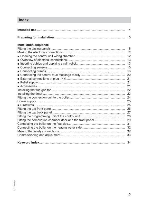
Intended use....................................................................................................... 4
Preparing for installation................................................................................... 5
Installation sequenceFitting the casing panels....................................................................................... 8Making the electrical connections........................................................................ 12■ Opening the control unit wiring chamber.......................................................... 12■ Overview of electrical connections.................................................................... 13■ Inserting cables and applying strain relief......................................................... 13■ Connecting sensors.......................................................................................... 15■ Connecting pumps............................................................................................ 16■ Connecting the central fault message facility.................................................... 20■ External connections at plug aVD..................................................................... 21■ Pellet supply...................................................................................................... 21■ Accessories....................................................................................................... 21Installing the flue gas fan...................................................................................... 22Installing the timer................................................................................................ 23Fitting the connection unit to the boiler................................................................. 24Power supply........................................................................................................ 25■ Directives.......................................................................................................... 25Fitting the top front panel...................................................................................... 26Fitting the top back panel..................................................................................... 27Fitting the programming unit of the control unit.................................................... 28Fitting the combustion chamber door and the front panel.................................... 29Connecting the boiler on the flue side.................................................................. 31Connecting the boiler on the heating water side.................................................. 32Making the safety connections............................................................................. 32Commissioning and adjustment........................................................................... 33
Keyword index.................................................................................................... 34
Index54
43 4
51 G
B

4
The appliance is only intended to beinstalled and operated in sealed unven-ted heating systems that comply withEN 12828, with due attention paid to theassociated installation, service andoperating instructions. It is only designedfor the heating of water that is of potablewater quality.
Intended usage presupposes that a fixedinstallation in conjunction with permissi-ble, system-specific components hasbeen carried out.
Commercial or industrial usage for a pur-pose other than heating the building orDHW does not comply with regulations.
Any usage beyond this must beapproved by the manufacturer for theindividual case.
Incorrect usage or operation of the appli-ance (e.g. the appliance being openedby the system user) is prohibited andresults in an exclusion of liability. Incor-rect usage also occurs if the componentsin the heating system are modified fromtheir intended function (e.g. if the fluegas and ventilation air paths aresealed).
Intended use
5443
451
GB
5
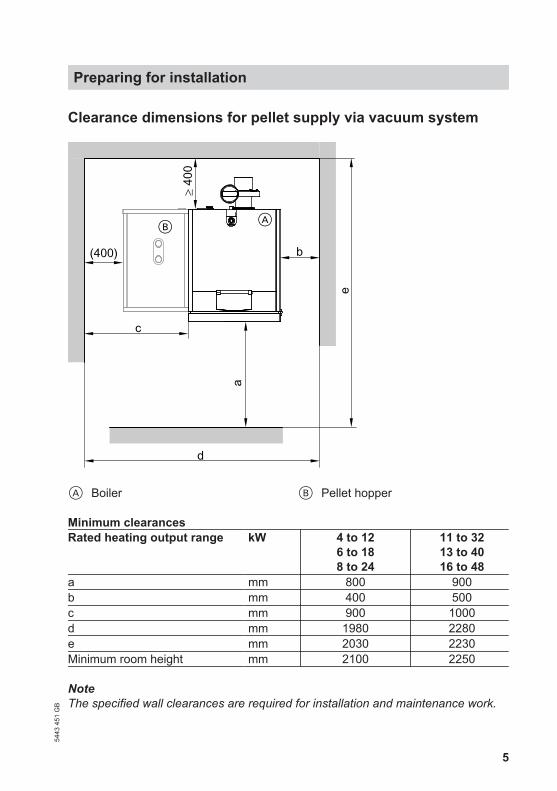
Clearance dimensions for pellet supply via vacuum system
e
a
≥ 40
0
(400)
B
c
b
d
A
A Boiler B Pellet hopper
Minimum clearancesRated heating output range kW 4 to 12
6 to 188 to 24
11 to 3213 to 4016 to 48
a mm 800 900b mm 400 500c mm 900 1000d mm 1980 2280e mm 2030 2230Minimum room height mm 2100 2250
NoteThe specified wall clearances are required for installation and maintenance work.
Preparing for installation54
43 4
51 G
B
6
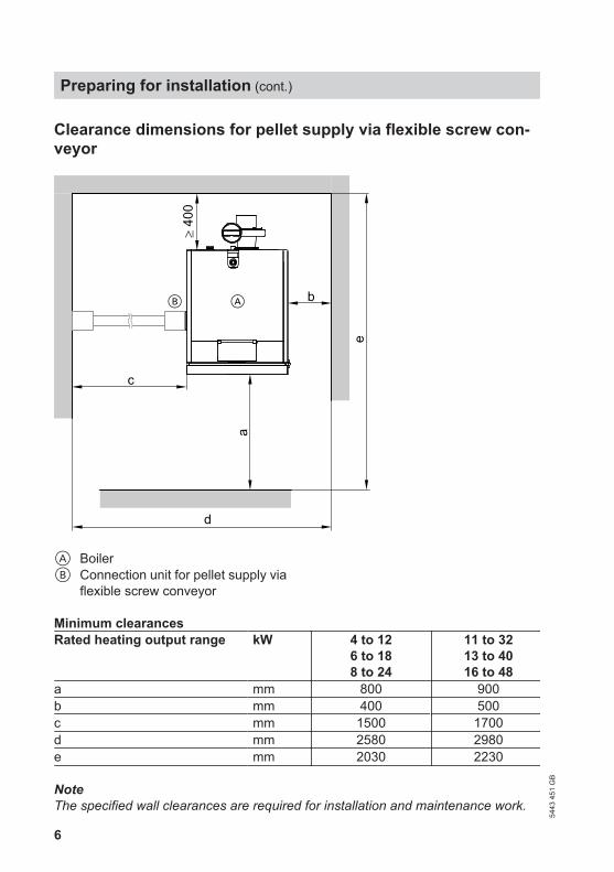
Clearance dimensions for pellet supply via flexible screw con-veyor
e
d
a
c
≥ 40
0
bAB
A BoilerB Connection unit for pellet supply via
flexible screw conveyor
Minimum clearancesRated heating output range kW 4 to 12
6 to 188 to 24
11 to 3213 to 4016 to 48
a mm 800 900b mm 400 500c mm 1500 1700d mm 2580 2980e mm 2030 2230
NoteThe specified wall clearances are required for installation and maintenance work.
Preparing for installation (cont.)
5443
451
GB
7
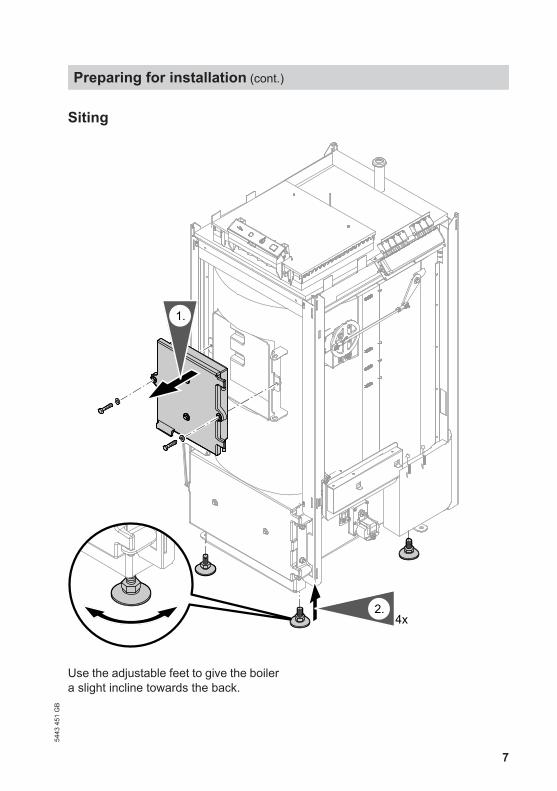
Siting
4x2.
1.
Use the adjustable feet to give the boilera slight incline towards the back.
Preparing for installation (cont.)
5443
451
GB

8
1.
3.9x9.5
2.
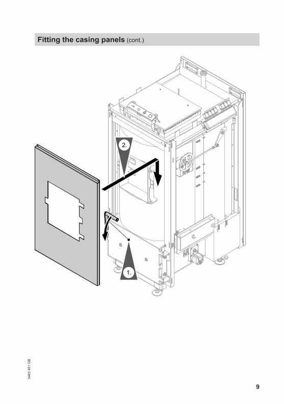
Fitting the casing panels
5443
451
GB
9
1.
2.
Fitting the casing panels (cont.)
5443
451
GB
10
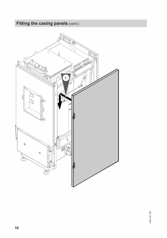
1.
Fitting the casing panels (cont.)
5443
451
GB
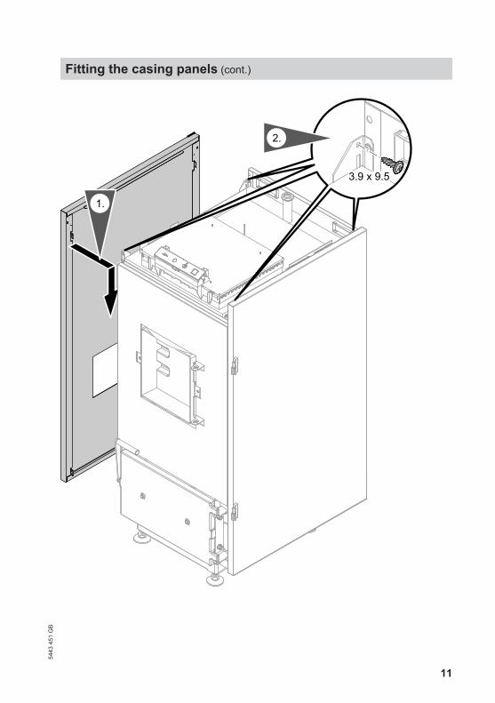
11
1.
3.9 x 9.5
2.
Fitting the casing panels (cont.)
5443
451
GB
12
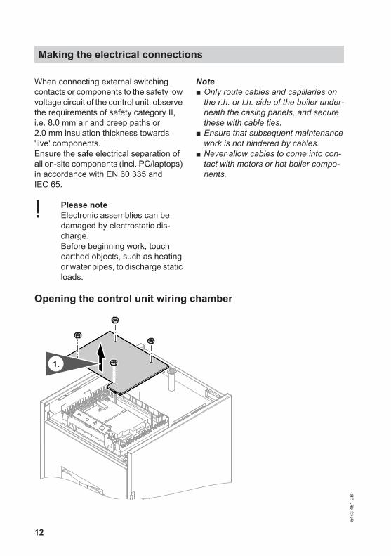
When connecting external switchingcontacts or components to the safety lowvoltage circuit of the control unit, observethe requirements of safety category II,i.e. 8.0 mm air and creep paths or2.0 mm insulation thickness towards'live' components.Ensure the safe electrical separation ofall on-site components (incl. PC/laptops)in accordance with EN 60 335 andIEC 65.
! Please noteElectronic assemblies can bedamaged by electrostatic dis-charge.Before beginning work, touchearthed objects, such as heatingor water pipes, to discharge staticloads.
Note■ Only route cables and capillaries on
the r.h. or l.h. side of the boiler under-neath the casing panels, and securethese with cable ties.
■ Ensure that subsequent maintenancework is not hindered by cables.
■ Never allow cables to come into con-tact with motors or hot boiler compo-nents.
Opening the control unit wiring chamber
1.
Making the electrical connections
5443
451
GB
13
Overview of electrical connections
Service instructions and plug-inconnection diagram
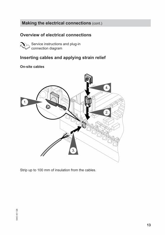
Inserting cables and applying strain relief
On-site cables
2.
1.
3.
4.
Strip up to 100 mm of insulation from the cables.
Making the electrical connections (cont.)
5443
451
GB
14
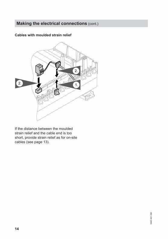
Cables with moulded strain relief
2. 1.
2.
If the distance between the mouldedstrain relief and the cable end is tooshort, provide strain relief as for on-sitecables (see page 13).
Making the electrical connections (cont.)
5443
451
GB
15
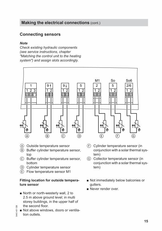
Connecting sensors
NoteCheck existing hydraulic components(see service instructions, chapter"Matching the control unit to the heatingsystem") and assign slots accordingly.
9 51 2 1 2 1 2 1 2 1 2
D E
11 2 3
A B C F
9 2 51 2
G
2/6M1 So So6
A Outside temperature sensorB Buffer cylinder temperature sensor,
topC Buffer cylinder temperature sensor,
bottomD Cylinder temperature sensorE Flow temperature sensor M1
F Cylinder temperature sensor (inconjunction with a solar thermal sys-tem)
G Collector temperature sensor (inconjunction with a solar thermal sys-tem)
Fitting location for outside tempera-ture sensor
■ North or north-westerly wall, 2 to2.5 m above ground level; in multistorey buildings, in the upper half ofthe second floor.
■ Not above windows, doors or ventila-tion outlets.
■ Not immediately below balconies orgutters.
■ Never render over.
Making the electrical connections (cont.)
5443
451
GB

16
Outside temperature sensor connec-tion
2-core lead, up to 35 m long with a cross-section of 1.5 mm2
Connecting pumps
Available pump connections
sÖ M1 Heating circuit pumpsÖ M2 Heating circuit pump
orsF Solar circuit pumpsA Circulation pump for cylinder
heating
sK DHW circulation pumpsL Boiler circuit pump in conjunc-
tion with the heating water buffercylinder
Pumps 230 V~
B
A1~M
A PumpB To the control unit
Rated current 4(2) A~Recommended connecting cable H05VV-F3G
0.75 mm2
or H05RN-F3G0.75 mm2
Making the electrical connections (cont.)
5443
451
GB

17
Pumps with power consumption greater than 2 A
LN
ExternalON/OFF
L N
N PE
NL
L
D
C
AB
A PumpB To the control unitC Contactor
D Separate power connection(observe manufacturer's details)
Making the electrical connections (cont.)
5443
451
GB
18
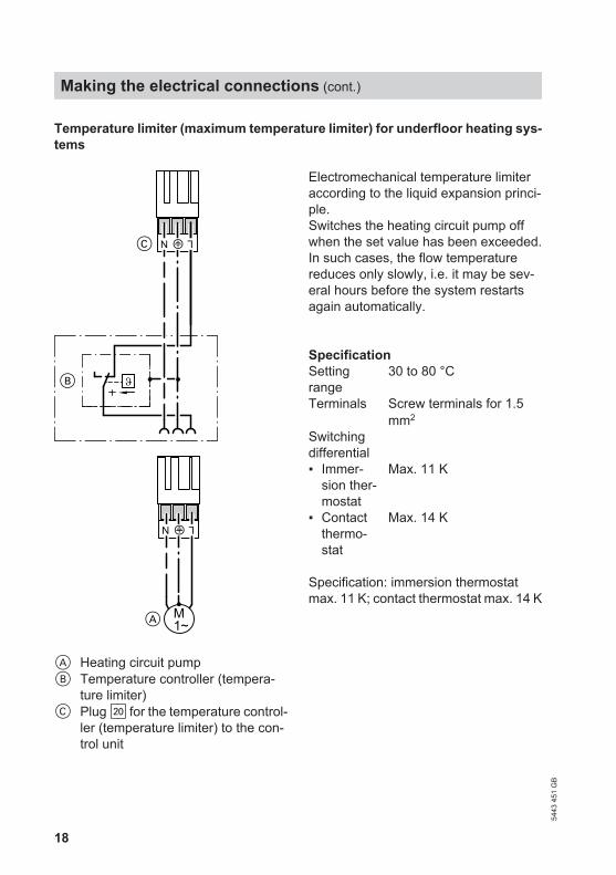
Temperature limiter (maximum temperature limiter) for underfloor heating sys-tems
LN ?
1~M
LN ?
C
B
A
A Heating circuit pumpB Temperature controller (tempera-
ture limiter)C Plug sÖ for the temperature control-
ler (temperature limiter) to the con-trol unit
Electromechanical temperature limiteraccording to the liquid expansion princi-ple.Switches the heating circuit pump offwhen the set value has been exceeded.In such cases, the flow temperaturereduces only slowly, i.e. it may be sev-eral hours before the system restartsagain automatically.
SpecificationSettingrange
30 to 80 °C
Terminals Screw terminals for 1.5mm2
Switchingdifferential
▪ Immer-sion ther-mostat
Max. 11 K
▪ Contactthermo-stat
Max. 14 K
Specification: immersion thermostatmax. 11 K; contact thermostat max. 14 K
Making the electrical connections (cont.)
5443
451
GB
19
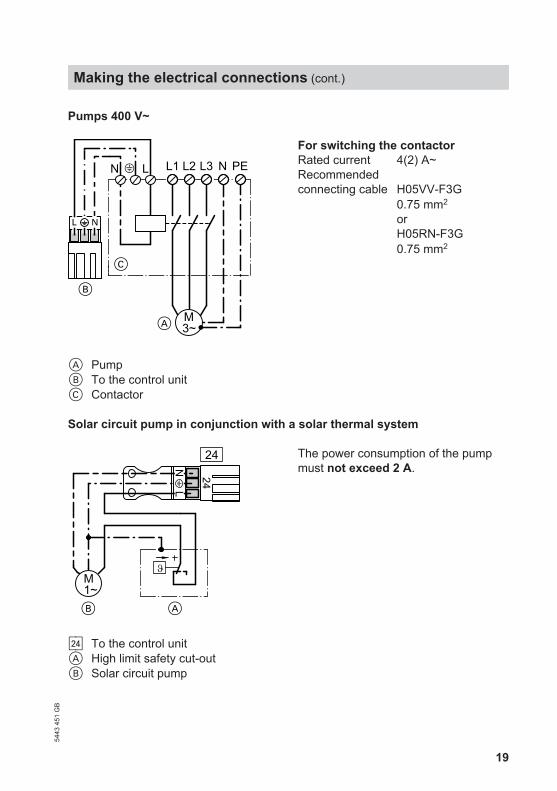
Pumps 400 V~
LN L1 L2 L3 N PE
A
C
3~M
B
A PumpB To the control unitC Contactor
For switching the contactorRated current 4(2) A~Recommended connecting cable H05VV-F3G
0.75 mm2
or H05RN-F3G0.75 mm2
Solar circuit pump in conjunction with a solar thermal system
1~M
B A
24
LN
24
sF To the control unitA High limit safety cut-outB Solar circuit pump
The power consumption of the pumpmust not exceed 2 A.
Making the electrical connections (cont.)
5443
451
GB
20
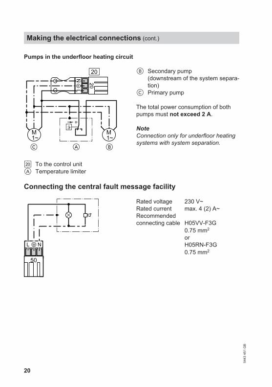
Pumps in the underfloor heating circuit
1~M
1~M
C A B
20
LN
20
sÖ To the control unitA Temperature limiter
B Secondary pump(downstream of the system separa-tion)
C Primary pump
The total power consumption of bothpumps must not exceed 2 A.
NoteConnection only for underfloor heatingsystems with system separation.
Connecting the central fault message facility
50
L N
Rated voltage 230 V~Rated current max. 4 (2) A~Recommended connecting cable H05VV-F3G
0.75 mm2
or H05RN-F3G0.75 mm2
Making the electrical connections (cont.)
5443
451
GB
21
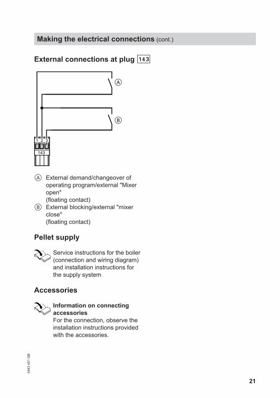
External connections at plug aVD
143
B
A
1 2 3
A External demand/changeover ofoperating program/external "Mixeropen"(floating contact)
B External blocking/external "mixerclose"(floating contact)
Pellet supply
Service instructions for the boiler(connection and wiring diagram)and installation instructions forthe supply system
Accessories
Information on connectingaccessoriesFor the connection, observe theinstallation instructions providedwith the accessories.
Making the electrical connections (cont.)
5443
451
GB
22
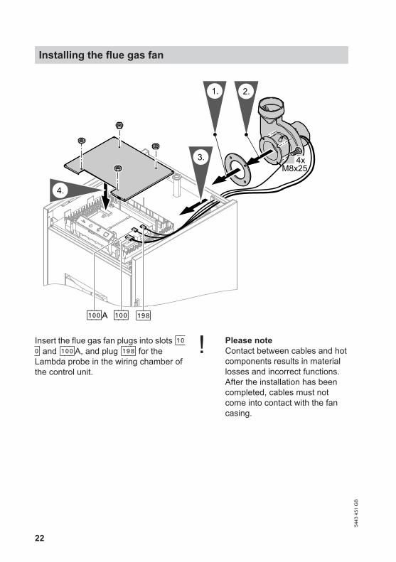
a-Öa-ÖA
M8x254x
2.1.
4.
3.
a:K
Insert the flue gas fan plugs into slots a-Ö and a-ÖA, and plug a:K for theLambda probe in the wiring chamber ofthe control unit.
! Please noteContact between cables and hotcomponents results in materiallosses and incorrect functions.After the installation has beencompleted, cables must notcome into contact with the fancasing.
Installing the flue gas fan
5443
451
GB
23
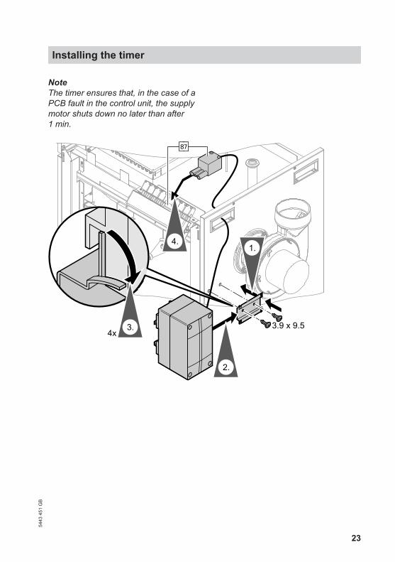
NoteThe timer ensures that, in the case of aPCB fault in the control unit, the supplymotor shuts down no later than after1 min.
kJ
2.
1.4.
3. 3.9 x 9.54x
Installing the timer54
43 4
51 G
B
24
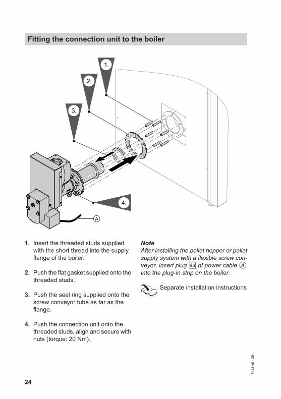
2.
4.
1.
A
3.
1. Insert the threaded studs suppliedwith the short thread into the supplyflange of the boiler.
2. Push the flat gasket supplied onto thethreaded studs.
3. Push the seal ring supplied onto thescrew conveyor tube as far as theflange.
4. Push the connection unit onto thethreaded studs, align and secure withnuts (torque: 20 Nm).
NoteAfter installing the pellet hopper or pelletsupply system with a flexible screw con-veyor, insert plug kD of power cable Ainto the plug-in strip on the boiler.
Separate installation instructions
Fitting the connection unit to the boiler
5443
451
GB
25
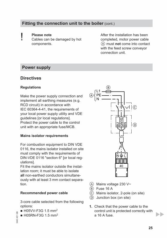
! Please noteCables can be damaged by hotcomponents.
After the installation has beencompleted, motor power cableA must not come into contactwith the feed screw conveyorconnection unit.
Power supply
Directives
Regulations
Make the power supply connection andimplement all earthing measures (e.g.RCD circuit) in accordance withIEC 60364-4-41, the requirements ofyour local power supply utility and VDEguidelines [or local regulations].Protect the power cable to the controlunit with an appropriate fuse/MCB.
Mains isolator requirements
For combustion equipment to DIN VDE0116, the mains isolator installed on sitemust comply with the requirements ofDIN-VDE 0116 "section 6" [or local reg-ulations].Fit the mains isolator outside the instal-lation room; it must be able to isolateall non-earthed conductors simultane-ously with at least 3 mm contact separa-tion.
Recommended power cable
3-core cable selected from the followingoptions:■ H05VV-F3G 1.5 mm2
■ H05RN-F3G 1.5 mm2
L1PEN
BU BNGN
YE
N L
40
A Mains voltage 230 V~B Fuse 16 AC Mains isolator, 2-pole (on site)D Junction box (on site)
1. Check that the power cable to thecontrol unit is protected correctly witha 16 A fuse.
Fitting the connection unit to the boiler (cont.)
5443
451
GB
26
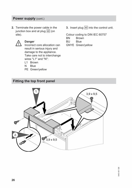
2. Terminate the power cable in thejunction box and at plug fÖ (onsite).
DangerIncorrect core allocation canresult in serious injury anddamage to the appliance.Take care not to interchangewires "L1" and "N":L1 BrownN BluePE Green/yellow
3. Insert plug fÖ into the control unit.
Colour coding to DIN IEC 60757BN BrownBU BlueGNYE Green/yellow
Fitting the top front panel
3,9 x 9,52.
3,9 x 9,51.
Power supply (cont.)
5443
451
GB
27
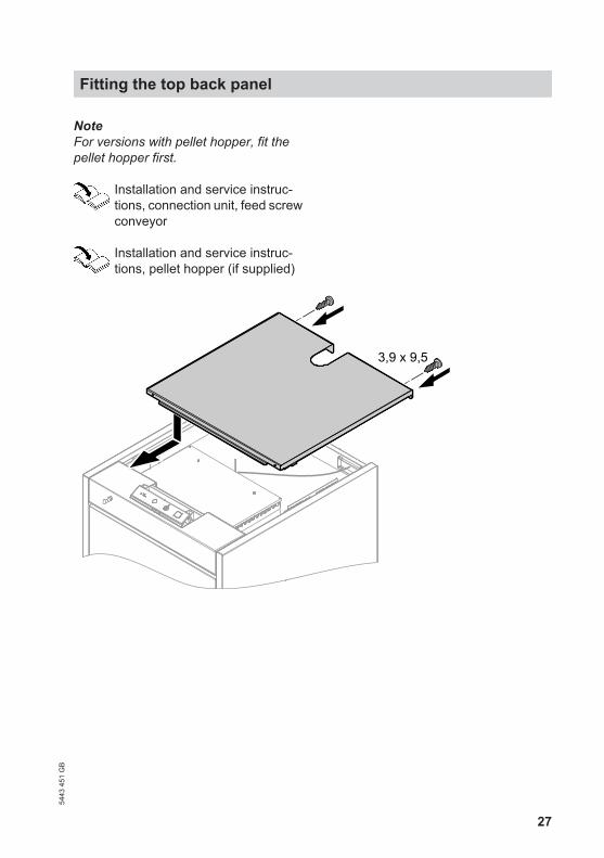
NoteFor versions with pellet hopper, fit thepellet hopper first.
Installation and service instruc-tions, connection unit, feed screwconveyor
Installation and service instruc-tions, pellet hopper (if supplied)
3,9 x 9,5
Fitting the top back panel54
43 4
51 G
B
28
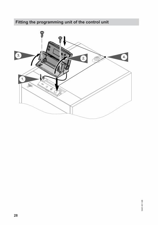
1.
2. 4.3.
Fitting the programming unit of the control unit
5443
451
GB
29
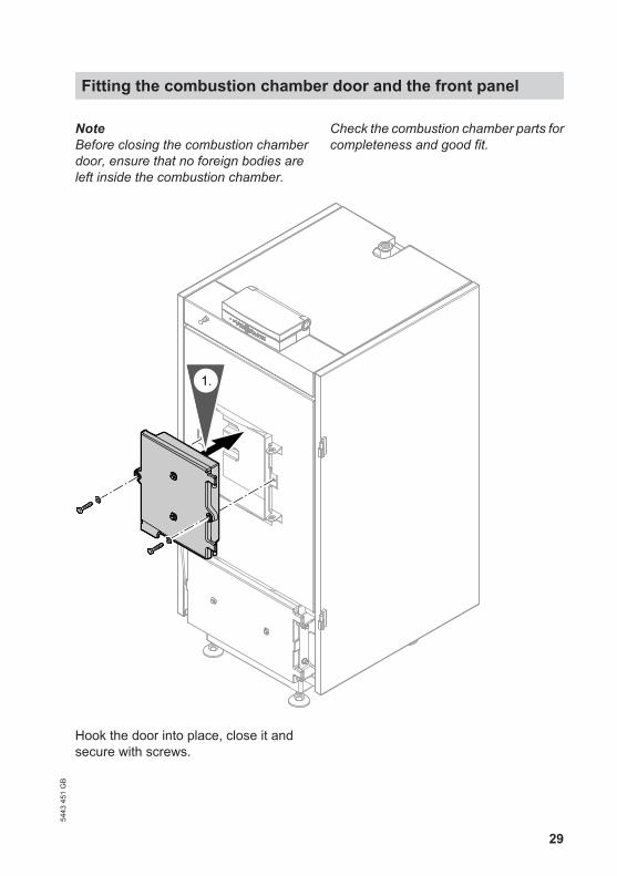
NoteBefore closing the combustion chamberdoor, ensure that no foreign bodies areleft inside the combustion chamber.
Check the combustion chamber parts forcompleteness and good fit.
1.
Hook the door into place, close it andsecure with screws.
Fitting the combustion chamber door and the front panel54
43 4
51 G
B
30
2.
A
4.
3.
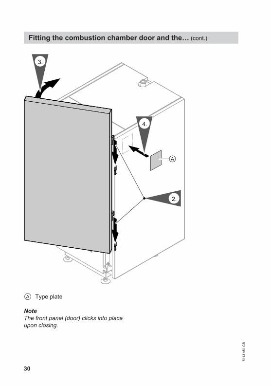
A Type plate
NoteThe front panel (door) clicks into placeupon closing.
Fitting the combustion chamber door and the… (cont.)
5443
451
GB
31
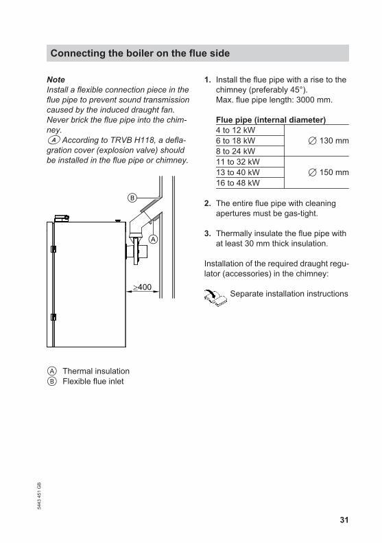
NoteInstall a flexible connection piece in theflue pipe to prevent sound transmissioncaused by the induced draught fan.Never brick the flue pipe into the chim-ney.a According to TRVB H118, a defla-gration cover (explosion valve) shouldbe installed in the flue pipe or chimney.
≥400
A Thermal insulationB Flexible flue inlet
1. Install the flue pipe with a rise to thechimney (preferably 45°).Max. flue pipe length: 3000 mm.
Flue pipe (internal diameter)4 to 12 kW
7 130 mm6 to 18 kW 8 to 24 kW 11 to 32 kW
7 150 mm13 to 40 kW16 to 48 kW
2. The entire flue pipe with cleaningapertures must be gas-tight.
3. Thermally insulate the flue pipe withat least 30 mm thick insulation.
Installation of the required draught regu-lator (accessories) in the chimney:
Separate installation instructions
Connecting the boiler on the flue side54
43 4
51 G
B
32
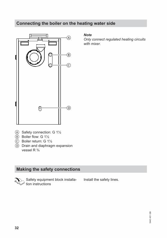
A Safety connection: G 1½B Boiler flow: G 1½C Boiler return: G 1½D Drain and diaphragm expansion
vessel R ¾
NoteOnly connect regulated heating circuitswith mixer.
Making the safety connections
Safety equipment block installa-tion instructions
Install the safety lines.
Connecting the boiler on the heating water side
5443
451
GB

33
Minimum cross-sectionsOutputBoiler
Pipe to the expan-sion vessel
Safety valveInlet connection Discharge pipe
4 to 12 kW DN 15 (R ½)
DN 15 (R ½) DN 20 (R ¾)
6 to 18 kW 8 to 24 kW
DN 20 (R ¾)11 to 32 kW13 to 40 kW16 to 48 kW
Permiss. operating pressure: 3 bar(0.3 MPa)Test pressure: 4 bar (0.4 MPa)
NoteEquip boilers with a safety valve that istype-tested to TRD 721 [or local regula-tions] and is marked according to thesystem version.
Commissioning and adjustment
Boiler service instructions andoperating instructions
Use the checklist supplied to prepare forand carry out commissioning. After com-missioning, the fully completed checklistmust be kept with the service documen-tation near the system.
Making the safety connections (cont.)
5443
451
GB
34
BBoiler water temperature sensor........15
CCentral fault message facility.............20Connection■ Expansion vessel............................32■ Flue side.........................................31■ Heating water side..........................32■ Safety valve....................................32Cylinder temperature sensor..............15
EElectrical connections........................12External connections..........................21
FFlue gas temperature sensor.............15
IInserting cables and applying strainrelief...................................................13
LLocation of boiler..............................5, 6LV connections..................................15
MMains isolator.....................................25
OOutside temperature sensor..............15
PPlug aVD............................................21Power cable.......................................25Power supply.....................................25Pumps■ Connecting.....................................16
RReturn temperature sensor................15
SSafety connections.............................32Sensors..............................................15
WWall clearances................................5, 6
Keyword index
5443
451
GB

35
54
43 4
51 G
B

36
Viessmann LimitedHortonwood 30, TelfordShropshire, TF1 7YP, GBTelephone: +44 1952 675000Fax: +44 1952 675040E-mail: [email protected]
Viessmann Werke GmbH&Co KGD-35107 AllendorfTelephone: +49 6452 70-0Fax: +49 6452 70-2780www.viessmann.com
5443
451
GB
Sub
ject
to te
chni
cal m
odifi
catio
ns.


![Vitoligno 300-P 20pp A4 web[1]](https://img.pdfslide.us/doc/110x75/5431f963219acdd64e8b557a/vitoligno-300-p-20pp-a4-web1.jpg)