Embed Size (px)
Citation preview
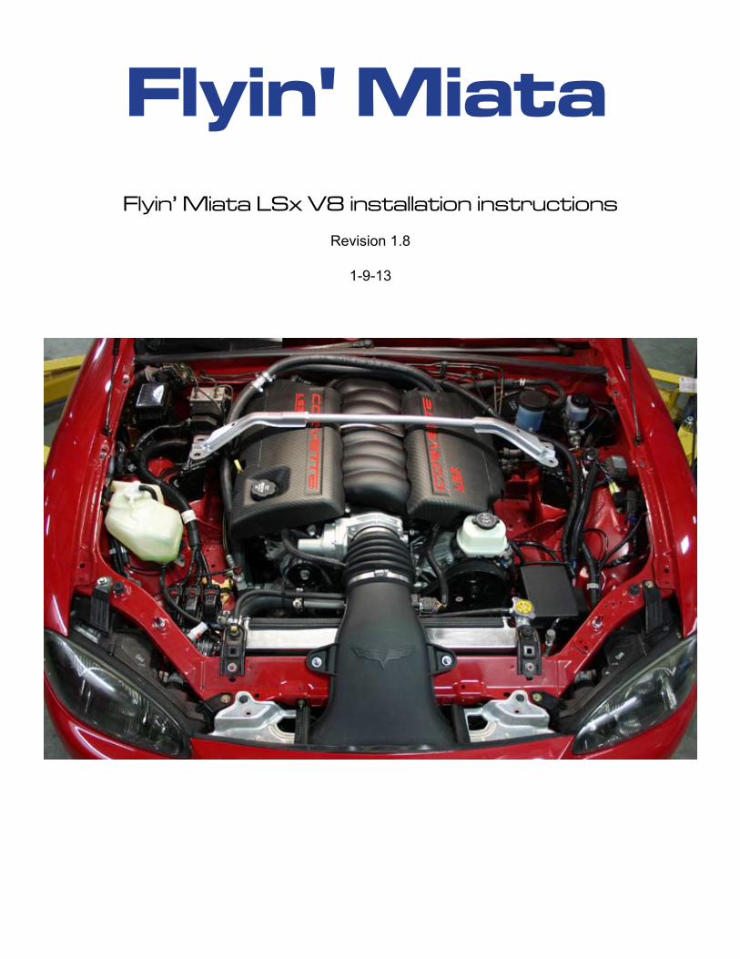
Flyin’ Miata LSx V8 installation instructions
Revision 1.8
1-9-13
Flyin' Miata
�Flyin' Miata970.464.5600 Rev 1.7, 12-14-12
Introduction
Thank you for purchasing the Flyin’ Miata LSx V8 conversion. We regard the installation as a mutual project and will be pleased to offer help at any time. We remain committed to make this a successful and enjoyable experience for all concerned. These instructions will offer the installer a guide for the installation of the Flyin’ Miata LSx V8 conversion for the first and second generation ('90 - '05) Mazda Miatas. Any instructions that don't apply for all years are clearly marked. These instructions make reference to various kits, that we assume you’ve purchased from us. If you haven’t, you’ll either need to do so or figure out what to do on your own.
STOP!Please read through these directions entirely before starting the project. Evaluate your own skills hon-estly and decide whether this installation is something that you are comfortable doing. Realize that you are basically re-building your entire car. If all you’ve done up to this point are oil changes, this is NOT a good project for you. This will require thorough knowledge of cars and specifically Miatas, the ability to completely strip the car, reassemble the car, fabrication skills and critical thinking. The last one is important. We’re happy to help, but you have to be able to problem-solve. You must be hon-est with yourself with respect to your skill level before you jump into the deep end. These instructions tell you what to do, and in what order, but they shouldn’t be regarded as being 100% complete. Part of this is because we’re assuming a certain skill level, part of this is because each installation will vary somewhat. If you have any concerns, either discuss the process with us or pay a professional to do the installation. These instructions only cover installing the LSx drivetrain, they do not cover other things that may happen at the same time. For example, if you’re also installing a roll bar, you’ll want to break at the appropriate time to do that. It’s up to you to determine the appropriate time.
The success of this installation will be determined by a variety of factors. These instructions should be adhered to unless reasonable cause for deviation exists. Care and attention to detail by the installer are of extreme importance. The daily operator of the vehicle must observe all operational guidelines.
Inventory all the components when the kit arrives. We strive to ensure all the components are in-cluded in the kit, but if a part is left out you will want to know it before you are looking for it during the installation. Plus, this will allow you to familiarize yourself with the parts in the conversion kit.
Prior to starting the installation, go through 2 tanks of the highest octane fuel available, if necessary for the motor you’re installing. Using lower octane fuel than what’s called for will result in knock that could damage the engine. If you anticipate this installation taking a long time, drain the tank and refill once the car is ready to run.
All left or right directional references will be from the driver viewpoint. If clarification of these instruc-tions is required, please contact us at 970-464-5600 or via e-mail @ [email protected]. Sugges-tions for improvements of these instructions are welcome. Please make notes on the instruction set and mail to: Flyin’ Miata, 499 35 Rd, Palisade, CO 81526.
These instructions and the operational requirements for this system must be reviewed with the owner-driver prior to delivery of the vehicle to the end user.
�Flyin' Miata970.464.5600 Rev 1.7, 12-14-12
ContentsIntroduction ............................................................................... 2Tool and Equipment Requirements .......................................... 4Section 1: Disassembly ........................................................... 5Section 2: Frame / body modification ...................................... 7Section 3: Brake, Clutch and Fuel Plumbing .........................11Section 4: Engine and Transmission Prep ........................... 12Section 5: Interior .................................................................. 15Section 6: Rear Subframe ..................................................... 17Section 7: Engine Mounting ................................................... 18Section 8: Accessories ........................................................... 20Section 9: Finishing touches................................................... 22
�Flyin' Miata970.464.5600 Rev 1.7, 12-14-12
Tool and Equipment Requirements
Every project on your Miata presents the opportunity to purchase more tools. Below are some of the tools and supplies you will need for the successful installation of this conversion kit. Tools SuppliesMetric open/box end wrenches Oil filter and fresh oil Metric socket set Spray can of cleaning solventRazor blade(s) Clean rags Assorted slot and Phillips screw drivers Paint RemoverMetric allen wrenches Silicone sealant (“The Right Stuff” is best)Funnel Loctite (blue)Floor jack Seam sealerJack stands x 4 Duct tape Welder (MIG / wire is typically easiest / best) Paint for the engine bayHammer Marker/paint penEye protection Grease Hacksaw / sawzall / some type of cutter Teflon tape/paste(plasma cutter is best) Penetrating oil (“PB Blaster” is best)Organizing tray (to keep fasteners straight) Sand paperFactory shop manual or equivalent Hand drill with ½” chuckAs many other tools as possible - this is a big job requiring a lot of tools
Torque values
Bellhousing to Transmission - 36 ft-lbsBellhousing to engine - 35 ft-lbsFlywheel - 15 ft-lbs, then 37 ft-lbs, then 74 ft-lbs. Torque all bolts to a given value before torquing to the next value.Pressure plate - 52 ft-lbsOil pan - 18-20 ft-lbsExhaust manifold - 11 ft-lbs then 15 ft-lbs. Again torque all bolts before moving onto the next torque value.Rear axle nuts - 225 ft-lbs. These need to be re-checked every few hundred miles until the car has 1000 miles on the swap.
Preliminary
1) If you have AC, get it professionally evacuated before you start disassembling.
2) Raise the car and support with jack stands / put it on a lift.
�Flyin' Miata970.464.5600 Rev 1.7, 12-14-12
Section 1: Disassembly
NOTE: As you’re disassembling everything, try to be as organized as possible. We highly recom-mend plastic trays with individual compartments (that you label). You might know exactly where that bolt goes now, but will you remember in a month or a year?
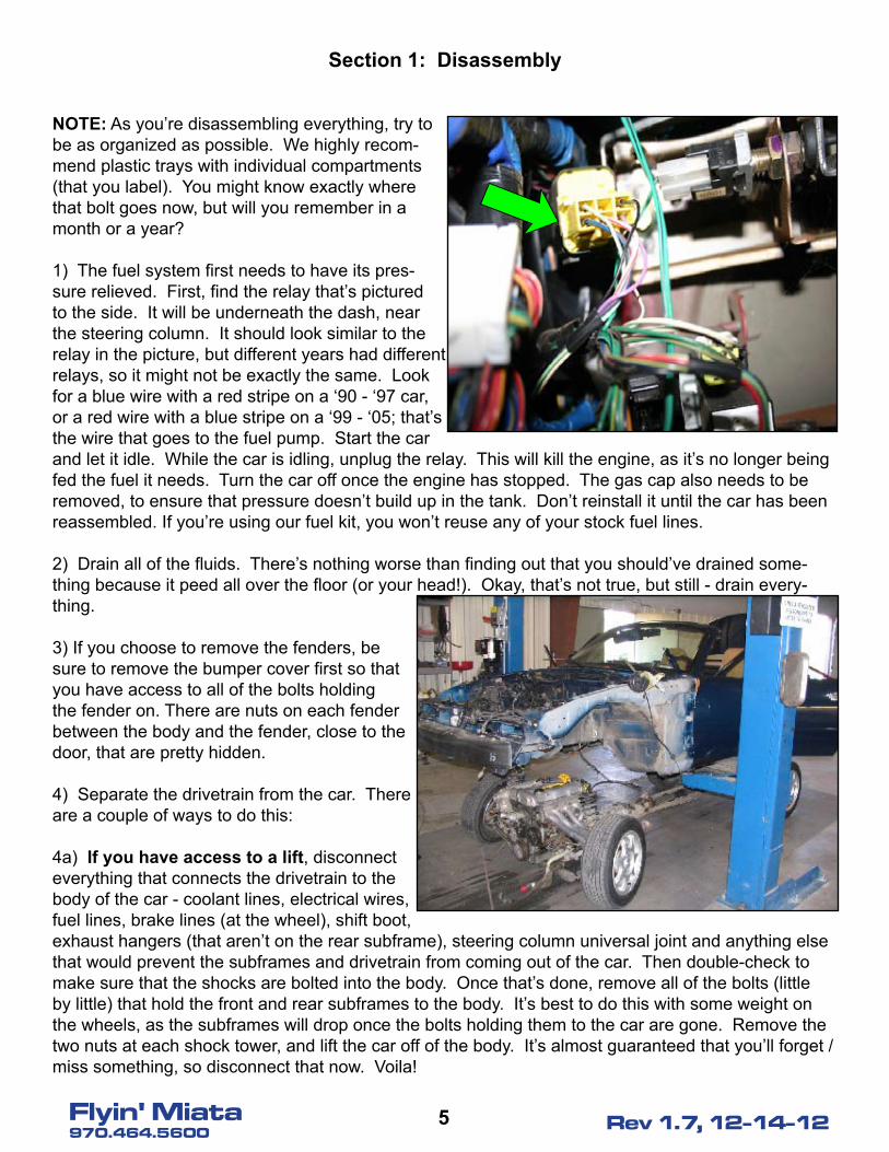
1) The fuel system first needs to have its pres-sure relieved. First, find the relay that’s pictured to the side. It will be underneath the dash, near the steering column. It should look similar to the relay in the picture, but different years had different relays, so it might not be exactly the same. Look for a blue wire with a red stripe on a ‘90 - ‘97 car, or a red wire with a blue stripe on a ‘99 - ‘05; that’s the wire that goes to the fuel pump. Start the car and let it idle. While the car is idling, unplug the relay. This will kill the engine, as it’s no longer being fed the fuel it needs. Turn the car off once the engine has stopped. The gas cap also needs to be removed, to ensure that pressure doesn’t build up in the tank. Don’t reinstall it until the car has been reassembled. If you’re using our fuel kit, you won’t reuse any of your stock fuel lines.
2) Drain all of the fluids. There’s nothing worse than finding out that you should’ve drained some-thing because it peed all over the floor (or your head!). Okay, that’s not true, but still - drain every-thing.
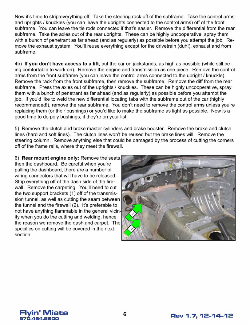
3) If you choose to remove the fenders, be sure to remove the bumper cover first so that you have access to all of the bolts holding the fender on. There are nuts on each fender between the body and the fender, close to the door, that are pretty hidden.
4) Separate the drivetrain from the car. There are a couple of ways to do this:
4a) If you have access to a lift, disconnect everything that connects the drivetrain to the body of the car - coolant lines, electrical wires, fuel lines, brake lines (at the wheel), shift boot, exhaust hangers (that aren’t on the rear subframe), steering column universal joint and anything else that would prevent the subframes and drivetrain from coming out of the car. Then double-check to make sure that the shocks are bolted into the body. Once that’s done, remove all of the bolts (little by little) that hold the front and rear subframes to the body. It’s best to do this with some weight on the wheels, as the subframes will drop once the bolts holding them to the car are gone. Remove the two nuts at each shock tower, and lift the car off of the body. It’s almost guaranteed that you’ll forget / miss something, so disconnect that now. Voila!
�Flyin' Miata970.464.5600 Rev 1.7, 12-14-12
Now it’s time to strip everything off. Take the steering rack off of the subframe. Take the control arms and uprights / knuckles (you can leave the uprights connected to the control arms) off of the front subframe. You can leave the tie rods connected if that’s easier. Remove the differential from the rear subframe. Take the axles out of the rear uprights. These can be highly uncooperative, spray them with a bunch of penetrant as far ahead (and as regularly) as possible before you attempt the job. Re-move the exhaust system. You’ll reuse everything except for the drivetrain (duh!), exhaust and from subframe.
4b) If you don’t have access to a lift, put the car on jackstands, as high as possible (while still be-ing comfortable to work on). Remove the engine and transmission as one piece. Remove the control arms from the front subframe (you can leave the control arms connected to the upright / knuckle). Remove the rack from the front subframe, then remove the subframe. Remove the diff from the rear subframe. Press the axles out of the uprights / knuckles. These can be highly uncooperative, spray them with a bunch of penetrant as far ahead (and as regularly) as possible before you attempt the job. If you’d like to weld the new differential locating tabs with the subframe out of the car (highly recommended!), remove the rear subframe. You don’t need to remove the control arms unless you’re replacing them (or their bushings) or you’d like to make the subframe as light as possible. Now is a good time to do poly bushings, if they’re on your list.
5) Remove the clutch and brake master cylinders and brake booster. Remove the brake and clutch lines (hard and soft lines). The clutch lines won’t be reused but the brake lines will. Remove the steering column. Remove anything else that could be damaged by the process of cutting the corners off of the frame rails, where they meet the firewall.
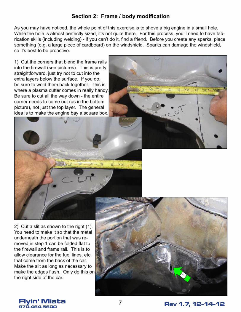
6) Rear mount engine only: Remove the seats, then the dashboard. Be careful when you’re pulling the dashboard, there are a number of wiring connectors that will have to be released. Strip everything off of the dash side of the fire-wall. Remove the carpeting. You’ll need to cut the two support brackets (1) off of the transmis-sion tunnel, as well as cutting the seam between the tunnel and the firewall (2). It’s preferable to not have anything flammable in the general vicin-ity when you do the cutting and welding, hence the reason we remove the dash and carpet. The specifics on cutting will be covered in the next section.
2
1
�Flyin' Miata970.464.5600 Rev 1.7, 12-14-12
Section �: Frame / body modification
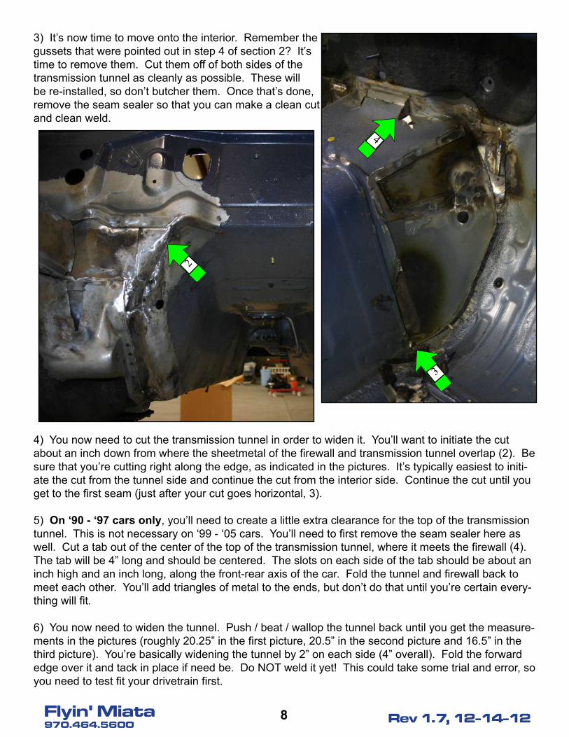
As you may have noticed, the whole point of this exercise is to shove a big engine in a small hole. While the hole is almost perfectly sized, it’s not quite there. For this process, you’ll need to have fab-rication skills (including welding) - if you can’t do it, find a friend. Before you create any sparks, place something (e.g. a large piece of cardboard) on the windshield. Sparks can damage the windshield, so it’s best to be proactive. 1) Cut the corners that blend the frame rails into the firewall (see pictures). This is pretty straightforward, just try not to cut into the extra layers below the surface. If you do, be sure to weld them back together. This is where a plasma cutter comes in really handy. Be sure to cut all the way down - the entire corner needs to come out (as in the bottom picture), not just the top layer. The general idea is to make the engine bay a square box.
2) Cut a slit as shown to the right (1). You need to make it so that the metal underneath the portion that was re-moved in step 1 can be folded flat to the firewall and frame rail. This is to allow clearance for the fuel lines, etc. that come from the back of the car. Make the slit as long as necessary to make the edges flush. Only do this on the right side of the car. 1
�Flyin' Miata970.464.5600 Rev 1.7, 12-14-12
3) It’s now time to move onto the interior. Remember the gussets that were pointed out in step 4 of section 2? It’s time to remove them. Cut them off of both sides of the transmission tunnel as cleanly as possible. These will be re-installed, so don’t butcher them. Once that’s done, remove the seam sealer so that you can make a clean cut and clean weld.
4) You now need to cut the transmission tunnel in order to widen it. You’ll want to initiate the cut about an inch down from where the sheetmetal of the firewall and transmission tunnel overlap (2). Be sure that you’re cutting right along the edge, as indicated in the pictures. It’s typically easiest to initi-ate the cut from the tunnel side and continue the cut from the interior side. Continue the cut until you get to the first seam (just after your cut goes horizontal, 3).
5) On ‘90 - ‘9� cars only, you’ll need to create a little extra clearance for the top of the transmission tunnel. This is not necessary on ‘99 - ‘05 cars. You’ll need to first remove the seam sealer here as well. Cut a tab out of the center of the top of the transmission tunnel, where it meets the firewall (4). The tab will be 4” long and should be centered. The slots on each side of the tab should be about an inch high and an inch long, along the front-rear axis of the car. Fold the tunnel and firewall back to meet each other. You’ll add triangles of metal to the ends, but don’t do that until you’re certain every-thing will fit.
6) You now need to widen the tunnel. Push / beat / wallop the tunnel back until you get the measure-ments in the pictures (roughly 20.25” in the first picture, 20.5” in the second picture and 16.5” in the third picture). You’re basically widening the tunnel by 2” on each side (4” overall). Fold the forward edge over it and tack in place if need be. Do NOT weld it yet! This could take some trial and error, so you need to test fit your drivetrain first.
2
4
3

9Flyin' Miata970.464.5600 Rev 1.7, 12-14-12
7) There’s a switch on the passenger’s side of the transmission that you’ll have to make room in the tunnel for. Find the switch, measure from a known datum (e.g. the shifter), and use a ball peen hammer to make a dent. Watch the switch as you install the drivetrain and enlarge the hole if need be. Bear in mind that there will be a plug on this as well, so you need room for more than just the switch.
8) If you’re going to reuse your stock / four cylinder-compatible front sway bar, cut the stock sway bar brackets off. You’ll need to install the heavy duty sway bar brackets, but move them as far forward as possible. You’ll reuse the bolts that hold the bracket on, but open up the holes a bit to move them forward (4). Just make sure that the distance you move them is the same on both sides. It’s best to bolt and tack them into place, but don’t do that until the engine is in (next step). Locate the mounts such that the sway bar will clear everything, then bolt and tack. Then remove the sway bar. The far easier option is to buy our custom front sway bar - this doesn’t require any modification to the stock mounts. The heavy duty sway bar brackets are still recommended, but not required. The exception is the ‘90 - ‘93 cars; chances are that you’ll need to move the mounts forward AND get our custom sway bar for 1.6 (originally!) cars.
9) Put the subframe, engine and transmission in the car. Don’t make this more complex than it is, we’re just trying to test fit to see if the modifications are adequate. If you have a lift, you should be able to put the engine on the subframe then lower the car over it and bolt it into place. If you don’t, you’ll need to bolt the subframe in, then put the engine and transmission bellhousing on it. Don’t forget the motor mounts! Check to be sure the right head doesn’t touch the firewall, it’s pretty tight there. Also drop the radiator (with fans!) in to be sure that you have adequate clearance. Do this with the crank pulley installed on the engine, otherwise you’re potentially in for a nasty surprise. Once you’ve ensured that you have the proper fit, locate the frame rails. Bolt the transmission mount onto the transmission and locate the frame rails such that the plates on the mount and the rail line up. Indicate the location of the rails, then remove them. They’ll be installed later. Then pull the subframe, engine and bellhousing back out.
10a) ‘90 - ‘9� only: You now need to move the radiator mounts forward. You’ll need to cut the top (5) and bottom (6) radiator brackets and AC condenser bracket (7) off of each side. Now attach the brackets to the radiator and relocate them. You’ll need to move the radiator as far forward as pos-
4
10Flyin' Miata970.464.5600 Rev 1.7, 12-14-12
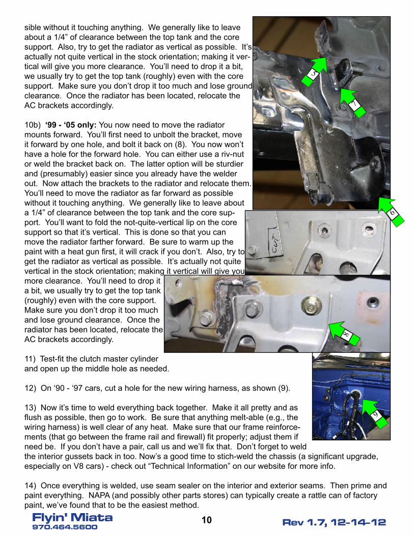
sible without it touching anything. We generally like to leave about a 1/4” of clearance between the top tank and the core support. Also, try to get the radiator as vertical as possible. It’s actually not quite vertical in the stock orientation; making it ver-tical will give you more clearance. You’ll need to drop it a bit, we usually try to get the top tank (roughly) even with the core support. Make sure you don’t drop it too much and lose ground clearance. Once the radiator has been located, relocate the AC brackets accordingly.
10b) ‘99 - ‘0� only: You now need to move the radiator mounts forward. You’ll first need to unbolt the bracket, move it forward by one hole, and bolt it back on (8). You now won’t have a hole for the forward hole. You can either use a riv-nut or weld the bracket back on. The latter option will be sturdier and (presumably) easier since you already have the welder out. Now attach the brackets to the radiator and relocate them. You’ll need to move the radiator as far forward as possible without it touching anything. We generally like to leave about a 1/4” of clearance between the top tank and the core sup-port. You’ll want to fold the not-quite-vertical lip on the core support so that it’s vertical. This is done so that you can move the radiator farther forward. Be sure to warm up the paint with a heat gun first, it will crack if you don’t. Also, try to get the radiator as vertical as possible. It’s actually not quite vertical in the stock orientation; making it vertical will give you more clearance. You’ll need to drop it a bit, we usually try to get the top tank (roughly) even with the core support. Make sure you don’t drop it too much and lose ground clearance. Once the radiator has been located, relocate the AC brackets accordingly.
11) Test-fit the clutch master cylinder and open up the middle hole as needed.
12) On ‘90 - ‘97 cars, cut a hole for the new wiring harness, as shown (9).
13) Now it’s time to weld everything back together. Make it all pretty and as flush as possible, then go to work. Be sure that anything melt-able (e.g., the wiring harness) is well clear of any heat. Make sure that our frame reinforce-ments (that go between the frame rail and firewall) fit properly; adjust them if need be. If you don’t have a pair, call us and we’ll fix that. Don’t forget to weld the interior gussets back in too. Now’s a good time to stich-weld the chassis (a significant upgrade, especially on V8 cars) - check out “Technical Information” on our website for more info.
14) Once everything is welded, use seam sealer on the interior and exterior seams. Then prime and paint everything. NAPA (and possibly other parts stores) can typically create a rattle can of factory paint, we’ve found that to be the easiest method.
6
5
7
8
9
11Flyin' Miata970.464.5600 Rev 1.7, 12-14-12
Section �: Brake, Clutch and Fuel Plumbing
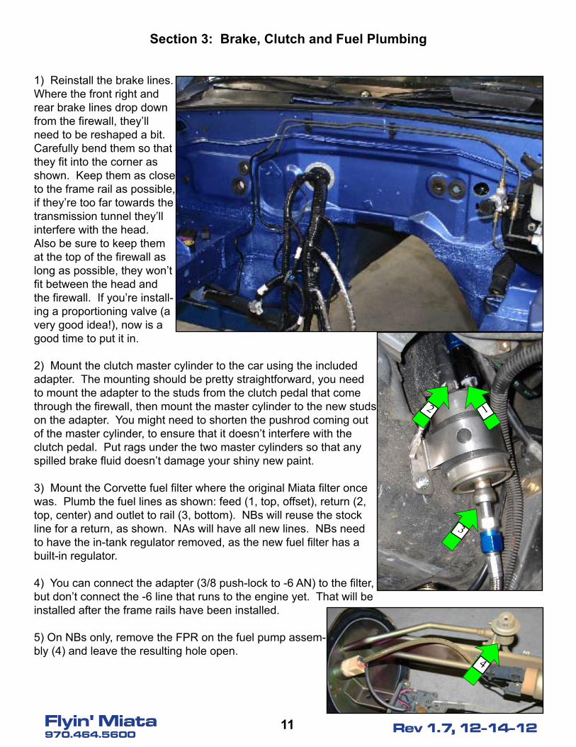
1) Reinstall the brake lines. Where the front right and rear brake lines drop down from the firewall, they’ll need to be reshaped a bit. Carefully bend them so that they fit into the corner as shown. Keep them as close to the frame rail as possible, if they’re too far towards the transmission tunnel they’ll interfere with the head. Also be sure to keep them at the top of the firewall as long as possible, they won’t fit between the head and the firewall. If you’re install-ing a proportioning valve (a very good idea!), now is a good time to put it in.
2) Mount the clutch master cylinder to the car using the included adapter. The mounting should be pretty straightforward, you need to mount the adapter to the studs from the clutch pedal that come through the firewall, then mount the master cylinder to the new studs on the adapter. You might need to shorten the pushrod coming out of the master cylinder, to ensure that it doesn’t interfere with the clutch pedal. Put rags under the two master cylinders so that any spilled brake fluid doesn’t damage your shiny new paint.
3) Mount the Corvette fuel filter where the original Miata filter once was. Plumb the fuel lines as shown: feed (1, top, offset), return (2, top, center) and outlet to rail (3, bottom). NBs will reuse the stock line for a return, as shown. NAs will have all new lines. NBs need to have the in-tank regulator removed, as the new fuel filter has a built-in regulator.
4) You can connect the adapter (3/8 push-lock to -6 AN) to the filter, but don’t connect the -6 line that runs to the engine yet. That will be installed after the frame rails have been installed.
5) On NBs only, remove the FPR on the fuel pump assem-bly (4) and leave the resulting hole open.
2 1
3
4
1�Flyin' Miata970.464.5600 Rev 1.7, 12-14-12
Section �: Engine and Transmission Prep
1) Mount the engine to an engine stand and thoroughly clean it, if necessary. Remove the exhaust manifolds. Cover the holes to ensure that no debris enters the engine. Cover the throttle body as well. Remove the flex plate if so equipped.
2) Install the Mazda temperature and pressure sensors onto the new motor. The oil pressure sensor should be installed at the rear of the galley between the heads using the included adapter. The ‘90 - ‘94 sensors require the use of an additional 90° piece. The water temperature sensor installs at the back of the passenger side head. You’ll need to remove the plug and install the sensor. ‘90 - ‘97s need the included adapter, ‘99 - ‘05s don’t need an adapter. You’ll need to run a new wire for the wa-ter temp sensor. If you have any additional / aftermarket sensors, now’s the time to install them.
3) Clean up the engine harness. If you bought a wiring harness from us, you won’t need to remove anything from the harness, but you will need to adjust lengths. You should take 8” out of the distance between the two cylinder banks (i.e., bring the wiring for the two banks closer to each other). For the portion of the harness that runs away from the motor, pull the bulkhead connector out of the harness (don’t cut it out, just untangle it). Set it aside. If you’re using our locations for the fuse box (see sec-tion 5, step 5) you’ll need to add 8’ (yes, feet) to the harness going away from the motor, but not to the bulkhead portion. Be sure of where you’re putting the fuse box before you cut anything. Do one wire at a time!! The same color wire is used multiple times, so it’s very easy to get lost if you do a bunch of wires at the same time. Bear in mind that solder is brittle and shouldn’t be used to connect two wires (ever seen such a solder joint in a factory wiring harness?). When you connect wires, use a high-quality heat-shrink butt connector. Tug on each connector to ensure that you got a good crimp. Try to offset the butt connectors so that you don’t have a huge lump of them. Run the tan/white wire to the Mazda oil pressure sensor you just installed and incorporate any new wires (you’ll have at least one for the water temp) into the harness. If you got a harness out of a salvage car, you’ll probably need to do quite a bit of stripping. Find a wiring diagram for that harness, determine what you need and what you don’t, and modify it. Also determine where you’d like to mount your PCM and adjust lengths as needed.
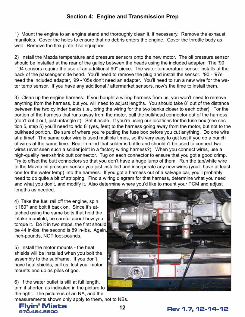
4) Take the fuel rail off the engine, spin it 180° and bolt it back on. Since it’s at-tached using the same bolts that hold the intake manifold, be careful about how you torque it. Do it in two steps, the first should be 44 in-lbs, the second is 89 in-lbs. Again, inch-pounds, NOT foot-pounds.
5) Install the motor mounts - the heat shields will be installed when you bolt the assembly to the subframe. If you don’t have heat shields, call us, lest your motor mounts end up as piles of goo.
6) If the water outlet is still at full length, trim it shorter, as indicated in the picture to the right. The picture is of an NA, and the measurements shown only apply to them, not to NBs.
1�Flyin' Miata970.464.5600 Rev 1.7, 12-14-12
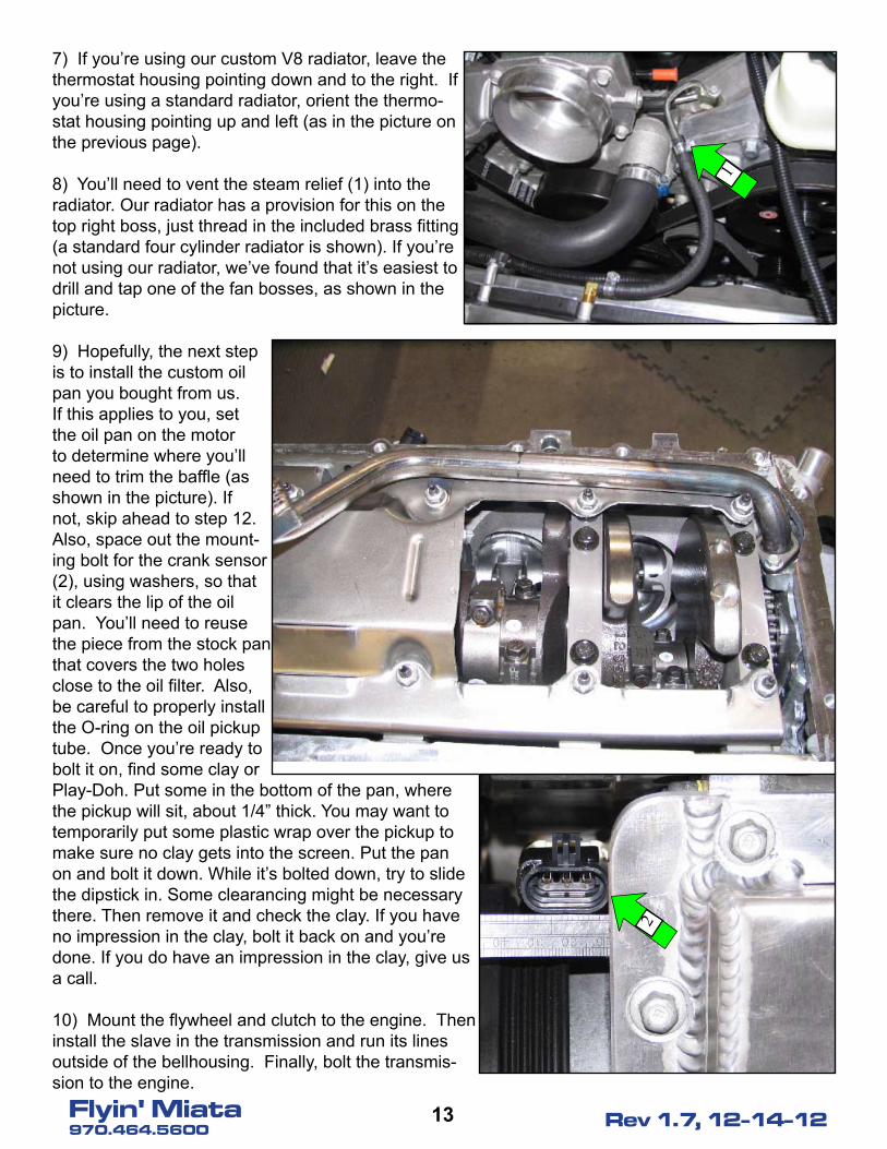
7) If you’re using our custom V8 radiator, leave the thermostat housing pointing down and to the right. If you’re using a standard radiator, orient the thermo-stat housing pointing up and left (as in the picture on the previous page).
8) You’ll need to vent the steam relief (1) into the radiator. Our radiator has a provision for this on the top right boss, just thread in the included brass fitting (a standard four cylinder radiator is shown). If you’re not using our radiator, we’ve found that it’s easiest to drill and tap one of the fan bosses, as shown in the picture.
9) Hopefully, the next step is to install the custom oil pan you bought from us. If this applies to you, set the oil pan on the motor to determine where you’ll need to trim the baffle (as shown in the picture). If not, skip ahead to step 12. Also, space out the mount-ing bolt for the crank sensor (2), using washers, so that it clears the lip of the oil pan. You’ll need to reuse the piece from the stock pan that covers the two holes close to the oil filter. Also, be careful to properly install the O-ring on the oil pickup tube. Once you’re ready to bolt it on, find some clay or Play-Doh. Put some in the bottom of the pan, where the pickup will sit, about 1/4” thick. You may want to temporarily put some plastic wrap over the pickup to make sure no clay gets into the screen. Put the pan on and bolt it down. While it’s bolted down, try to slide the dipstick in. Some clearancing might be necessary there. Then remove it and check the clay. If you have no impression in the clay, bolt it back on and you’re done. If you do have an impression in the clay, give us a call.
10) Mount the flywheel and clutch to the engine. Then install the slave in the transmission and run its lines outside of the bellhousing. Finally, bolt the transmis-sion to the engine.
2
1
1�Flyin' Miata970.464.5600 Rev 1.7, 12-14-12
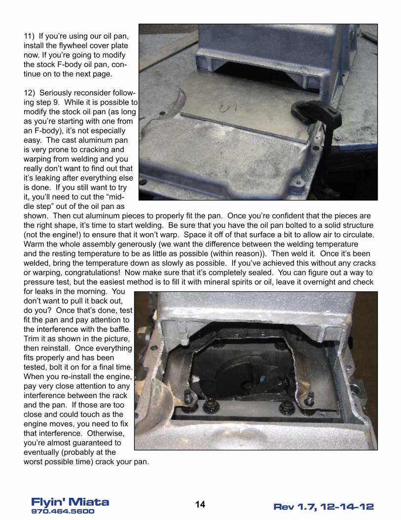
11) If you’re using our oil pan, install the flywheel cover plate now. If you’re going to modify the stock F-body oil pan, con-tinue on to the next page.
12) Seriously reconsider follow-ing step 9. While it is possible to modify the stock oil pan (as long as you’re starting with one from an F-body), it’s not especially easy. The cast aluminum pan is very prone to cracking and warping from welding and you really don’t want to find out that it’s leaking after everything else is done. If you still want to try it, you’ll need to cut the “mid-dle step” out of the oil pan as shown. Then cut aluminum pieces to properly fit the pan. Once you’re confident that the pieces are the right shape, it’s time to start welding. Be sure that you have the oil pan bolted to a solid structure (not the engine!) to ensure that it won’t warp. Space it off of that surface a bit to allow air to circulate. Warm the whole assembly generously (we want the difference between the welding temperature and the resting temperature to be as little as possible (within reason)). Then weld it. Once it’s been welded, bring the temperature down as slowly as possible. If you’ve achieved this without any cracks or warping, congratulations! Now make sure that it’s completely sealed. You can figure out a way to pressure test, but the easiest method is to fill it with mineral spirits or oil, leave it overnight and check for leaks in the morning. You don’t want to pull it back out, do you? Once that’s done, test fit the pan and pay attention to the interference with the baffle. Trim it as shown in the picture, then reinstall. Once everything fits properly and has been tested, bolt it on for a final time. When you re-install the engine, pay very close attention to any interference between the rack and the pan. If those are too close and could touch as the engine moves, you need to fix that interference. Otherwise, you’re almost guaranteed to eventually (probably at the worst possible time) crack your pan.
1�Flyin' Miata970.464.5600 Rev 1.7, 12-14-12
Section �: Interior
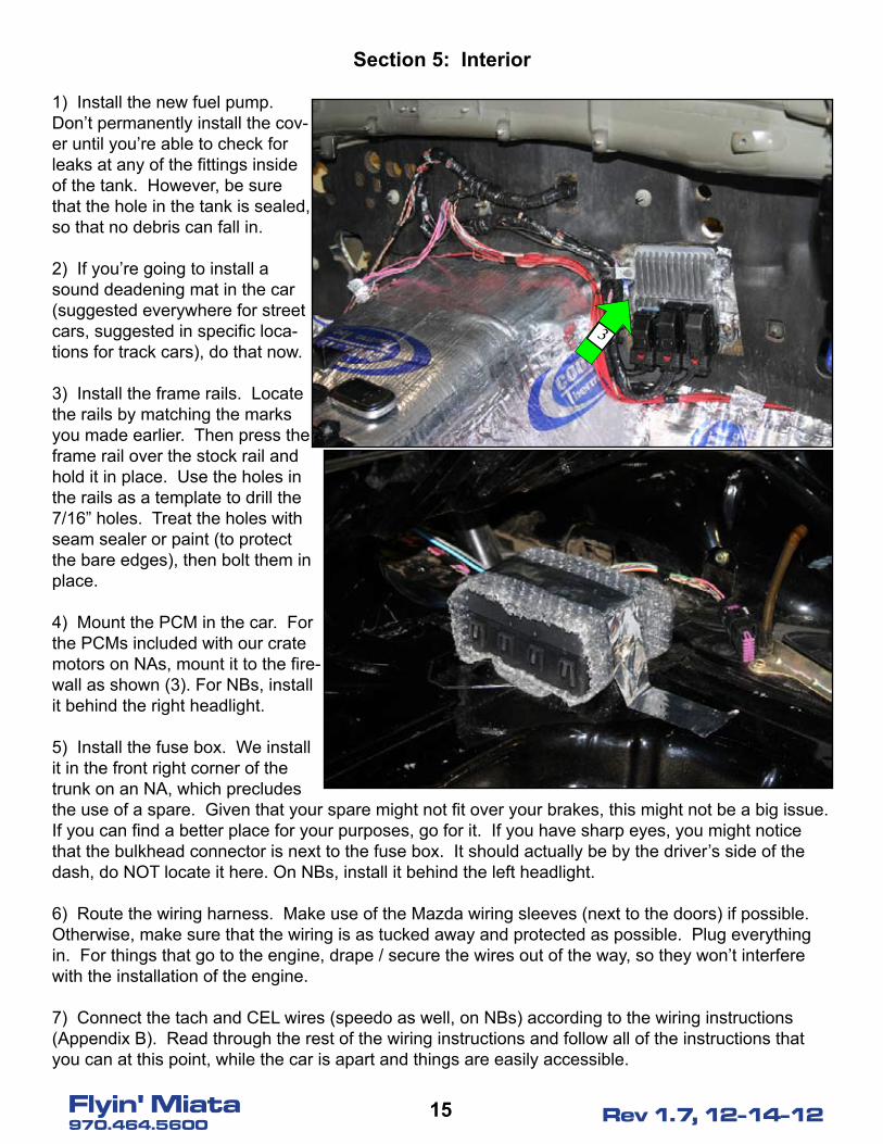
1) Install the new fuel pump. Don’t permanently install the cov-er until you’re able to check for leaks at any of the fittings inside of the tank. However, be sure that the hole in the tank is sealed, so that no debris can fall in.
2) If you’re going to install a sound deadening mat in the car (suggested everywhere for street cars, suggested in specific loca-tions for track cars), do that now.
3) Install the frame rails. Locate the rails by matching the marks you made earlier. Then press the frame rail over the stock rail and hold it in place. Use the holes in the rails as a template to drill the 7/16” holes. Treat the holes with seam sealer or paint (to protect the bare edges), then bolt them in place.
4) Mount the PCM in the car. For the PCMs included with our crate motors on NAs, mount it to the fire-wall as shown (3). For NBs, install it behind the right headlight.
5) Install the fuse box. We install it in the front right corner of the trunk on an NA, which precludes the use of a spare. Given that your spare might not fit over your brakes, this might not be a big issue. If you can find a better place for your purposes, go for it. If you have sharp eyes, you might notice that the bulkhead connector is next to the fuse box. It should actually be by the driver’s side of the dash, do NOT locate it here. On NBs, install it behind the left headlight.
6) Route the wiring harness. Make use of the Mazda wiring sleeves (next to the doors) if possible. Otherwise, make sure that the wiring is as tucked away and protected as possible. Plug everything in. For things that go to the engine, drape / secure the wires out of the way, so they won’t interfere with the installation of the engine.
7) Connect the tach and CEL wires (speedo as well, on NBs) according to the wiring instructions (Appendix B). Read through the rest of the wiring instructions and follow all of the instructions that you can at this point, while the car is apart and things are easily accessible.
3
1�Flyin' Miata970.464.5600 Rev 1.7, 12-14-12
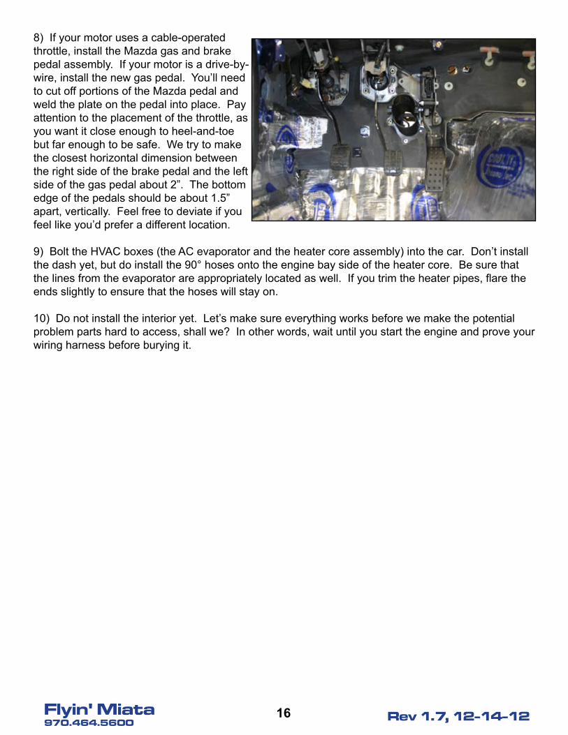
8) If your motor uses a cable-operated throttle, install the Mazda gas and brake pedal assembly. If your motor is a drive-by-wire, install the new gas pedal. You’ll need to cut off portions of the Mazda pedal and weld the plate on the pedal into place. Pay attention to the placement of the throttle, as you want it close enough to heel-and-toe but far enough to be safe. We try to make the closest horizontal dimension between the right side of the brake pedal and the left side of the gas pedal about 2”. The bottom edge of the pedals should be about 1.5” apart, vertically. Feel free to deviate if you feel like you’d prefer a different location.
9) Bolt the HVAC boxes (the AC evaporator and the heater core assembly) into the car. Don’t install the dash yet, but do install the 90° hoses onto the engine bay side of the heater core. Be sure that the lines from the evaporator are appropriately located as well. If you trim the heater pipes, flare the ends slightly to ensure that the hoses will stay on.
10) Do not install the interior yet. Let’s make sure everything works before we make the potential problem parts hard to access, shall we? In other words, wait until you start the engine and prove your wiring harness before burying it.
1�Flyin' Miata970.464.5600 Rev 1.7, 12-14-12
Section �: Rear Subframe
1) Remove the original diff bushing (have fun with that one!) and install the new diff bushing (if pur-chased, not a requirement). Then install the vent. You’ll attach a hose and remote breather to this later, to ensure that any fluid that comes out of the vent won’t leak out.
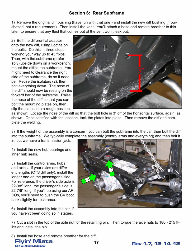
2) Bolt the differential adapter onto the new diff, using Loctite on the bolts. Do this in three steps, working your way up to 45 ft-lbs. Then, with the subframe (prefer-ably) upside down on a workbench, mount the diff to the subframe. You might need to clearance the right side of the subframe, do so if need be. Reuse the isolators (2), then bolt everything down. The nose of the diff should now be resting on the forward bar of the subframe. Raise the nose of the diff so that you can bolt the mounting plates on, then slip the plates into a rough position, as shown. Locate the nose of the diff so that the bolt hole is 3” off of the horizontal surface, again, as shown. Once satisfied with the location, tack the plates into place. Then remove the diff and com-plete the welding.
3) If the weight of the assembly is a concern, you can bolt the subframe into the car, then bolt the diff into the subframe. We typically complete the assembly (control arms and everything) and then bolt it in, but we have a transmission jack.
4) Install the new hub bearings and inner hub seals.
5) Install the control arms, hubs and axles. If your axles are differ-ent lengths (CTS diff only), install the longer one on the passenger’s side. For reference, the driver’s side axle is 22-3/8” long, the passenger’s side is 22-7/8” long. If you’ll be using our AF-COs, you’ll need to push the CV boot back slightly for clearance.
6) Install the assembly into the car, if you haven’t been doing so in stages.
7) Cut a slot in the top of the axle nut for the retaining pin. Then torque the axle nuts to 180 - 215 ft-lbs and install the pin.
8) Install the hose and remote breather for the diff.
2
1
3”
1�Flyin' Miata970.464.5600 Rev 1.7, 12-14-12
Section �: Engine Mounting
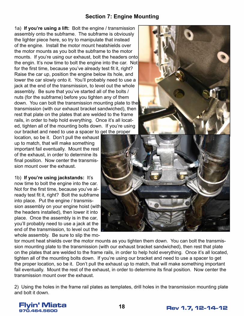
1a) If you’re using a lift: Bolt the engine / transmission assembly onto the subframe. The subframe is obviously the lighter piece here, so try to manipulate that instead of the engine. Install the motor mount heatshields over the motor mounts as you bolt the subframe to the motor mounts. If you’re using our exhaust, bolt the headers onto the engin. It’s now time to bolt the engine into the car. Not for the first time, because you’ve already test fit it, right? Raise the car up, position the engine below its hole, and lower the car slowly onto it. You’ll probably need to use a jack at the end of the transmission, to level out the whole assembly. Be sure that you’ve started all of the bolts / nuts (for the subframe) before you tighten any of them down. You can bolt the transmission mounting plate to the transmission (with our exhaust bracket sandwiched), then rest that plate on the plates that are welded to the frame rails, in order to help hold everything. Once it’s all locat-ed, tighten all of the mounting bolts down. If you’re using our bracket and need to use a spacer to get the proper location, so be it. Don’t pull the exhaust up to match, that will make something important fail eventually. Mount the rest of the exhaust, in order to determine its final position. Now center the transmis-sion mount over the exhaust. 1b) If you’re using jackstands: It’s now time to bolt the engine into the car. Not for the first time, because you’ve al-ready test fit it, right? Bolt the subframe into place. Put the engine / transmis-sion assembly on your engine hoist (with the headers installed), then lower it into place. Once the assembly is in the car, you’ll probably need to use a jack at the end of the transmission, to level out the whole assembly. Be sure to slip the mo-tor mount heat shields over the motor mounts as you tighten them down. You can bolt the transmis-sion mounting plate to the transmission (with our exhaust bracket sandwiched), then rest that plate on the plates that are welded to the frame rails, in order to help hold everything. Once it’s all located, tighten all of the mounting bolts down. If you’re using our bracket and need to use a spacer to get the proper location, so be it. Don’t pull the exhaust up to match, that will make something important fail eventually. Mount the rest of the exhaust, in order to determine its final position. Now center the transmission mount over the exhaust. 2) Using the holes in the frame rail plates as templates, drill holes in the transmission mounting plate and bolt it down.
19Flyin' Miata970.464.5600 Rev 1.7, 12-14-12
3) Install the driveshaft. Then bolt the driveshaft to the adapter (that was installed earlier and tighten the bolts to 45 ft-lbs in three steps. Use blue Loctite on all the bolts here.
4) Install or fabricate the exhaust system. On the right side header, you need to install the starter (with its heat shielding!) as you install the header. Ceramic coating is not a bad idea, especially if you have to satisfy emissions requirements. The ceramic helps maintain the heat in the exhaust system, which helps the cats “light off” faster. That having been said, ceramic coating is not necessary to en-sure that you don’t get a CEL / MIL.
5) Install the rest of the fuel system. Push the -6 adapter onto the fuel rail, then smear a little bit of motor oil onto the threads and taper. Then connect the -6 line to the fuel filter and run it to the front of the car, securing it as needed. Once it’s in the engine bay, thread it onto the adapter. Don’t over-tighten it, hand tight plus a 1/4 turn is usually good (technically, -6 fittings should be tightened to 16.25 ft-lbs). Be sure to test the system for leaks once it’s together enough to do so.
6) Bolt the stock ladder brace (the brace that connects the rear subframe to the car) back on (if your car has one). Make any modifications necessary for fitment (not necessary on all cars), but try to keep all of the attachment points in place.
7) Wire up the transmission’s wiring harness, per the wiring instructions (Appendix B).
8) Install the shift lever and shift boot.
9) Install the front A-arms and hubs.
�0Flyin' Miata970.464.5600 Rev 1.7, 12-14-12
Section �: Accessories
1) Now it’s time to bolt all of the other stuff to the engine. Install the alternator, power steering pump, A/C compressor and any pulleys and belts. Be certain that you’ve chosen the proper accessory setup, as some are deeper than others and won’t allow enough clearance for important things like a radiator and fans.
2) Connect the engine harness plugs to all of the appropriate places.
3) Install the radiator and fans. It’s typically easiest to bolt the fans to the radiator, then drop the whole assembly in.
4) Wire in the fans and A/C (if so equipped). Refer to Appendix B.
5) Install the vacuum lines.
6) Install the coolant lines. The line coming out of the thermostat should go to the lower fitting on the radiator, the line that comes out near the water pump should go to the upper fitting. If you’re having trouble routing the radiator hose from the driver’s side back to the thermostat, consider our V8 spe-cific radiator, which has a fitting of the proper size and orientation on the passenger’s side.
7) Install the steering rack and column.
8) Install the power steering lines. If you didn’t get a kit from us, bear in mind that the pressure side of the system works under very high pressure (hose clamps won’t be sufficient) and that you must have a cooler in the system. The cooler doesn’t have to be anything especially fancy, but you must have one. On the power steering pump’s high pressure outlet, it’s better to use a crush washer than the supplied O-ring.
9) Fabricate the intake. We’ve found that longer intakes make more power. I.e., it’s better to have the filter by the left shock tower than behind the headlight. Or, just buy our kit.
10) Fill and check all of the fluids. Try to fill the coolant with the front of the car as high as possible. Do a spot-check underneath to ensure that there are no leaks. Then, pressure test the system and check for leaks again.
11) Temporarily install the gauge cluster. The dashboard is still out, since we still need to prove the wiring.. right? Plug in anything else that is pertinent for the operation of the engine.
12) Install and connect the battery. We like to use Corvette batteries. Watch for any of the magic smoke when you connect the battery. If you see any of it, immediately disconnect the battery and find the source.
�1Flyin' Miata970.464.5600 Rev 1.7, 12-14-12
13) The big thing - start it! This is a test-start to prove out everything, so you don’t necessarily need to have everything done, but do be sure that enough is done for the engine to function properly and safely. Have a helper watch to ensure that you don’t have any leaks. It’s also a good idea to pause with the ignition on, to make sure that you don’t have any fuel leaking or smoke escaping (incorrectly wired electronics). Once you’re satisfied that everything’s functioning properly, start it up. You’ll see some smoke as greasy fingerprints and such burn off, but check carefully to ensure that everything’s functioning properly. If you’ve jumped the gun a bit and haven’t filled it with coolant yet, be sure you don’t let it idle for too long. Be sure that your tach matches the engine speed (an OBD-II scanner can be helpful here). If you get the motor warm enough (or you can control when your fans come on, e.g. with HP Tuners) make sure that your fans work. Bear in mind that the factory programming doesn’t turn the fans on until the car is well over 200° F. Once you’re convinced that everything is correct, shut it off.
14) Check the fluid levels and top off as necessary.
15) Now that you know your wiring is correct, re-install the interior (your gauges are working, right?).
16) If you’re going to install fuel rail covers, modify them to fit now. NA cars sometimes aren’t able to have the hood close with the fuel rail covers installed, but NB cars have enough clearance.
17) If you have A/C, fabricate and install those lines.
18) Install the brakes.
19) Install the shocks and springs. We highly recommend coilovers with appropriate spring rates - our standard AFCO setup and V-Maxx XXtreme track pack setup both work very well.
20) Install the front sway bar. If you don’t have enough clearance, slide the bushing mounts forward and / or pick up one of our custom sway bars.
21) Install the washer and coolant overflow bottles.
22) On NAs only, clearance the hood as needed. Be sure that you leave enough structure to keep the hood strong enough. NBs might need clearancing for the power steering reservoir, you’ll need to check.
23) On NAs only, install the hood struts that you got from us, since you can no longer use the stock prop rod. If you still need them (they’ll work on NBs too, they’re just not required), we carry them.
��Flyin' Miata970.464.5600 Rev 1.7, 12-14-12
Section 9: Finishing touches
1) Bleed the brakes.
2) Bleed the clutch.
3) Adjust the clutch pedal.
4) Check again for leaks.
5) Check the operation of all of your lights and signals.
6) If you haven’t done it already, check the fan operation.
7) You should’ve been making sure all of the bolts were properly tightened as you went. Think care-fully about whether you were waiting for something before you tightened some / any of the bolts. If there are any in question, double-check them. What about the lug nuts? Are those tight?
8) The fun part - go drive it! First, do a couple of slow speed but firm stops in a place where you won’t run into anything if they fail. Once you’re convinced that they’re functional, go drive. Take it easy at first and make sure that the car isn’t overheating, nothing’s loose, there aren’t any concerning vibrations, etc. Keep an especially close eye on the oil pressure and coolant temp. Don’t be afraid to shut the car down, leave it on the side of the road and pick it up later, if you get severe enough warn-ing signs - what’s worse, coming back with a trailer or buying a new engine? Chances are that there will be some rattles and noises, try to make notes about roughly where they’re coming from so that you can track them down later.
9) Once you come back and the car has cooled off, double-check the tightness of any potentially problematic bolts. The most important ones to check are the bolts between the driveshaft, adapter and differential. Beyond that, the more bolts you check, the better. Also make sure all of your hose clamps are tight - worm gear clamps often need to be tightened again, after being heated up.
10) Check the coolant and oil levels. Keep an especially close eye on these the first few times you drive the car. Don’t stop checking them until you’re confident that the coolant is completely full and the car isn’t burning oil.
11) Adjust the suspension, if necessary. If your suspension has the capability for cornerweighting, do that as well.
12) Get an alignment done. Most street cars will use the same specs that we use for four-cylinder cars (http://www.flyinmiata.com/tech/alignment.php).
13) Charge the AC, if so equipped.
14) Go drive it and have fun! You’re done! That having been said, bear in mind that you’ve just com-pletely rebuilt your car, and there are a number of things that could be wrong. Re-check the tightness of bolts and clamps. Keep a vigilant eye on any possible leaks, pay attention to any rattles or noises that could signify loose bolts, make sure the car isn’t burning oil or coolant (especially with a salvage motor) and generally pay attention to the car. If this is a brand new or rebuilt motor, be sure to follow the engine supplier’s break-in procedure.