Embed Size (px)
Citation preview
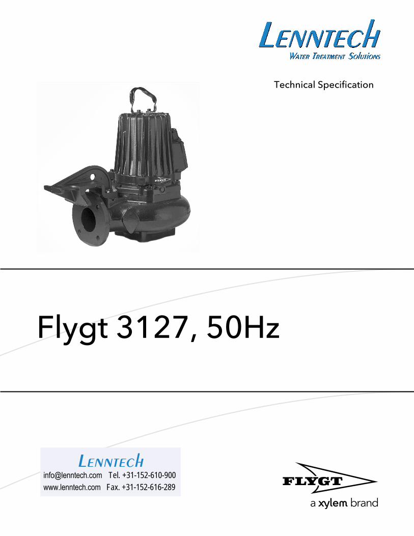
Technical Specification
Flygt 3127, 50Hz
[email protected] Tel. +31-152-610-900www.lenntech.com Fax. +31-152-616-289
Lenntech
Table of Contents
1 C-pump, Standard Motor.......................................................................................................... 31.1 Product description............................................................................................................. 31.2 Motor rating and performance curves.............................................................................. 5
2 C-pump, Premium Efficiency Motor (IE3)................................................................................92.1 Product description............................................................................................................. 92.2 Motor rating and performance curves............................................................................ 11
3 D-pump......................................................................................................................................153.1 Product description........................................................................................................... 153.2 Motor rating and performance curves............................................................................ 17
4 F-pump, Standard Motor.........................................................................................................204.1 Product description 3127.182/.091................................................................................ 204.2 Product description 3127.350/.390................................................................................ 234.3 Motor rating and performance curves 3127.182/.091................................................. 254.4 Motor rating and performance curves 3127.350/.390................................................. 26
5 F-pump, Premium Efficiency Motor (IE3).............................................................................. 305.1 Product description........................................................................................................... 30
5.1.1 Motor rating and performance curves.....................................................................32
6 H-pump...................................................................................................................................... 366.1 Product description........................................................................................................... 366.2 Motor rating and performance curves............................................................................ 38
7 L-pump.......................................................................................................................................407.1 Product description........................................................................................................... 407.2 Motor rating and performance curves............................................................................ 42
8 M-pump..................................................................................................................................... 448.1 Product description........................................................................................................... 448.2 Motor rating and performance curves............................................................................ 46
9 N-pump, Standard Motor........................................................................................................489.1 Product description........................................................................................................... 489.2 Motor rating and performance curves 3127.160/.190................................................. 519.3 Motor rating and performance curves 3127.185/.095................................................. 569.4 Motor rating and performance curves 3127.760/.770................................................. 60
10 N-pump, Premium Efficiency Motor (IE3)...........................................................................6410.1 Product description.........................................................................................................6410.2 Motor rating and performance curves 3127.820/.830............................................... 6710.3 Motor rating and performance curves 3127.900/.910............................................... 7010.4 Motor rating and performance curves 3127.960/.970............................................... 74
11 P-pump.................................................................................................................................... 7811.1 Product description.........................................................................................................78
Table of Contents
Flygt 3127, 50Hz Technical Specification 1
11.2 Motor rating and performance curves..........................................................................80
12 Dimensions and Weight, C-pump....................................................................................... 8212.1 Drawings...........................................................................................................................82
13 Dimensions and Weight, D-pump....................................................................................... 9013.1 Drawings...........................................................................................................................90
14 Dimensions and Weight, F-pump........................................................................................9214.1 Drawings...........................................................................................................................92
15 Dimensions and Weight, H-pump....................................................................................... 9915.1 Drawings...........................................................................................................................99
16 Dimensions and Weight, M-pump.................................................................................... 10016.1 Drawings.........................................................................................................................100
17 Dimensions and Weight, N-pump.....................................................................................10117.1 Drawings.........................................................................................................................101
18 Dimensions and Weight, P-pump......................................................................................11518.1 Drawings.........................................................................................................................115
Table of Contents
2 Flygt 3127, 50Hz Technical Specification
1 C-pump, Standard Motor1.1 Product description
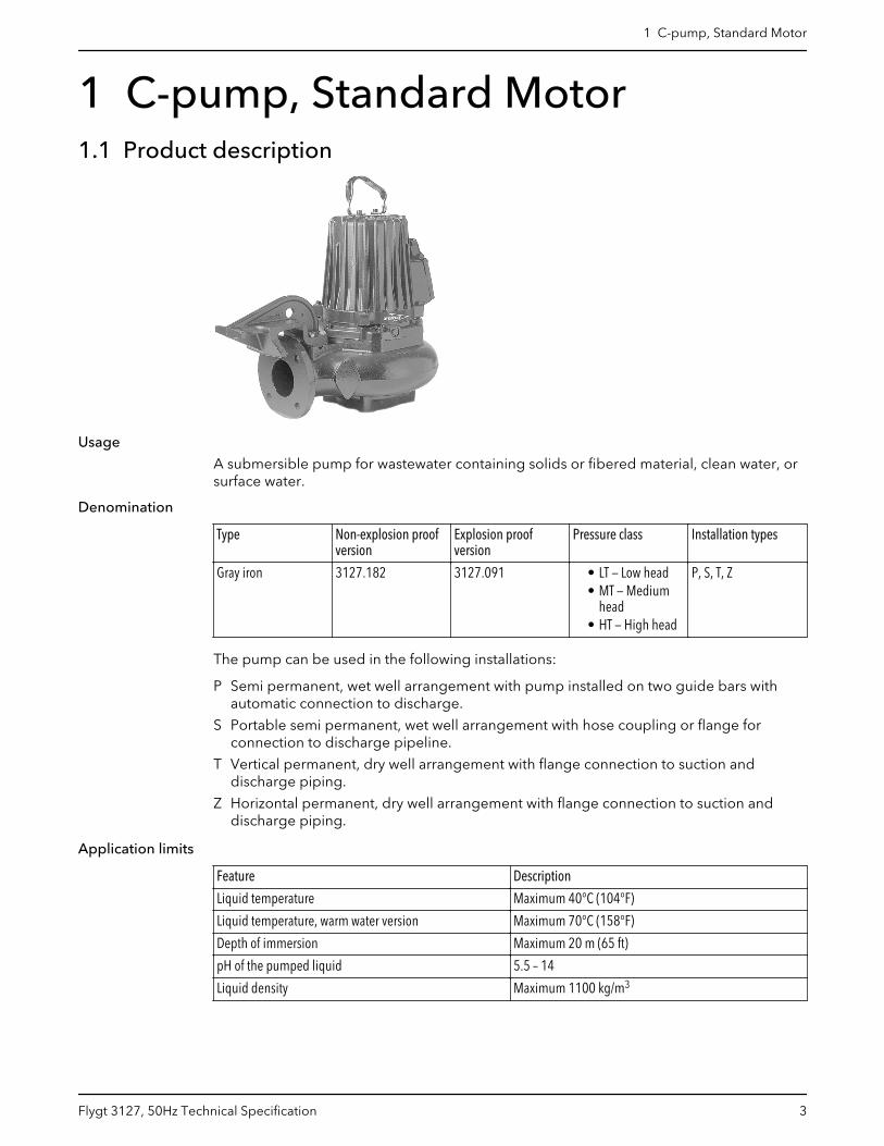
Usage
A submersible pump for wastewater containing solids or fibered material, clean water, orsurface water.
Denomination
Type Non-explosion proofversion
Explosion proofversion
Pressure class Installation types
Gray iron 3127.182 3127.091 • LT — Low head• MT — Medium
head• HT — High head
P, S, T, Z
The pump can be used in the following installations:
P Semi permanent, wet well arrangement with pump installed on two guide bars withautomatic connection to discharge.
S Portable semi permanent, wet well arrangement with hose coupling or flange forconnection to discharge pipeline.
T Vertical permanent, dry well arrangement with flange connection to suction anddischarge piping.
Z Horizontal permanent, dry well arrangement with flange connection to suction anddischarge piping.
Application limits
Feature Description
Liquid temperature Maximum 40°C (104°F)
Liquid temperature, warm water version Maximum 70°C (158°F)
Depth of immersion Maximum 20 m (65 ft)
pH of the pumped liquid 5.5 – 14
Liquid density Maximum 1100 kg/m3
1 C-pump, Standard Motor
Flygt 3127, 50Hz Technical Specification 3
Motor data
Feature Description
Motor type Squirrel-cage induction motor
Frequency 50 Hz
Power supply 3-phase
Starting method • Direct on-line• Star-delta• Soft starter• Variable Frequency Drive (VFD)
Number of starts per hour Maximum 30
Code compliance IEC 60034-1
Voltage variation • Continuously running: Maximum ±5%• Intermittent running: Maximum ±10%
Voltage imbalance betweenphases
Maximum 2%
Stator insulation class H (180°C, 356°F)
Cables
Application Type
Direct-on-line start or Y/D start with two cables Flygt SUBCAB® - a heavy duty 4 cores motor power cablewith two twisted pair screened control cores. Conductorinsulation rating of 90°C, which allows for increasedcurrent. Superior mechanical strength and high abrasionand tear resistant. Chemical resistant within pH 3-10 andozone, oil, and flame resistant. Used up to 70°C watertemperature. Cables < 10 mm2 with unscreened controlcores.
Y/D start Flygt SUBCAB® - a heavy duty 7 cores motor power cablewith two twisted pair screened control cores. Conductorinsulation rating of 90°C, which allows for increasedcurrent. Superior mechanical strength and high abrasionand tear resistant. Chemical resistant within pH 3-10 andozone, oil, and flame resistant. Used up to 70°C watertemperature. Cables < 7G6 mm2 with unscreenedcontrol cores.
Variable Frequency drive Screened Flygt SUBCAB® - a heavy duty 4 screened coresmotor power cable with four twisted pair screenedcontrol cores. Conductor insulation rating of 90°C, whichallows for increased current. Superior mechanicalstrength and high abrasion and tear resistant. Chemicalresistant within pH 3-10 and ozone, oil, and flameresistant. Used up to 70°C water temperature.
Monitoring equipment
Thermal contacts opening temperature 125° C (257° F)
Materials
Table 1: Major parts except mechanical seals
Denomination Material ASTM EN
Major castings Cast iron, gray 35B GJL-250
Pump housing Cast iron, gray 35B GJL-250
Impeller, alternative 1 Cast iron, gray 35B GJL-250
1 C-pump, Standard Motor
4 Flygt 3127, 50Hz Technical Specification
Denomination Material ASTM EN
Impeller, alternative 2 Cast iron, gray 30B GJL-200
Wear ring, alternative 1 Nitrile rubber (NBR) - -
Wear ring, alternative 2 Bronze C924 CC491K, CC492K
Lifting handle Stainless steel AISI 316L 1.4404,1.4432, …
Shaft Stainless steel AISI 431 1.4057+QT800
Screws and nuts Stainless steel, A4 AISI 316L, 316, 316Ti 1.4401,1.4404, …
O-rings, alternative 1 Nitrile rubber (NBR) 70° IRH - -
O-rings, alternative 2 Fluorinated rubber (FPM)70° IRH
- -
Oil, part no 901752 Medical white oil of paraffintype. Fulfills FDA 172.878(a)
- -
Table 2: Mechanical seals
Alternative Inner seal Outer seal
1 Aluminum oxide/ Corrosion resistantcemented carbide
Corrosion resistant cementedcarbide/ Corrosion resistantcemented carbide
2 Corrosion resistant cementedcarbide/ Corrosion resistantcemented carbide
Corrosion resistant cementedcarbide/ Corrosion resistantcemented carbide
3 Corrosion resistant cementedcarbide/ Corrosion resistantcemented carbide
Silicon carbide/ Silicon carbide
Surface treatment
Priming Finish
Painted with a primer, see internal standardM0700.00.0002
Navy gray color NCS 5804-B07G. Two-component high-solid top coating, see internal standard M0700.00.0004for standard painting and M0700.00.0008 for specialpainting.
Options
• Warm liquid version (non-explosion proof versions)• Leakage sensor in the stator housing (FLS)• Leakage sensor in the oil housing (CLS)• Surface treatment (Epoxy)• Zinc anodes• Other cables
Accessories
Discharge connections, adapters, hose connections, and other mechanical accessories.
Electrical accessories such as pump controller, control panels, starters, monitoring relays,cables.
1.2 Motor rating and performance curvesThese are examples of motor rating and curves. For more information, please contactyour local sales and service representative.
Star-delta starting current is 1/3 of Direct on-line starting current.
1 C-pump, Standard Motor
Flygt 3127, 50Hz Technical Specification 5
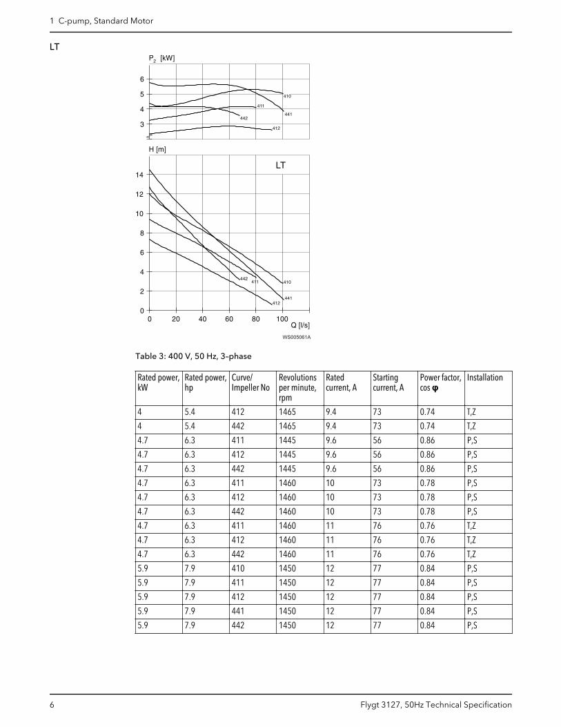
LT
WS005061A
Table 3: 400 V, 50 Hz, 3–phase
Rated power,kW
Rated power,hp
Curve/Impeller No
Revolutionsper minute,rpm
Ratedcurrent, A
Startingcurrent, A
Power factor,cos φ
Installation
4 5.4 412 1465 9.4 73 0.74 T,Z
4 5.4 442 1465 9.4 73 0.74 T,Z
4.7 6.3 411 1445 9.6 56 0.86 P,S
4.7 6.3 412 1445 9.6 56 0.86 P,S
4.7 6.3 442 1445 9.6 56 0.86 P,S
4.7 6.3 411 1460 10 73 0.78 P,S
4.7 6.3 412 1460 10 73 0.78 P,S
4.7 6.3 442 1460 10 73 0.78 P,S
4.7 6.3 411 1460 11 76 0.76 T,Z
4.7 6.3 412 1460 11 76 0.76 T,Z
4.7 6.3 442 1460 11 76 0.76 T,Z
5.9 7.9 410 1450 12 77 0.84 P,S
5.9 7.9 411 1450 12 77 0.84 P,S
5.9 7.9 412 1450 12 77 0.84 P,S
5.9 7.9 441 1450 12 77 0.84 P,S
5.9 7.9 442 1450 12 77 0.84 P,S
1 C-pump, Standard Motor
6 Flygt 3127, 50Hz Technical Specification
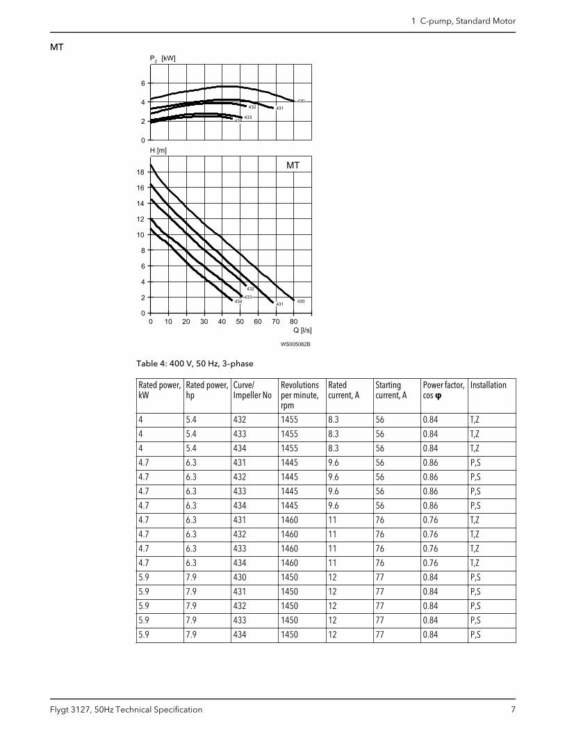
MT
Q [l/s]
H [m]
2P [kW]
0 10 20 30 40 50 60 70 800
2
4
6
8
10
12
14
16
18
0
2
4
6
MT
430
430
430
430
430
430
431
431
431
431
431
431
431
431
431
431
431
431
431
431
431
431
431
431
432
432
432
432
432
432
432
432
432
432
432
432
432
432
432
432
432
432
433
433
433
433
433
433
433
433
433
433
433
433
433
433
433
433
433
433
433
433
433
433
433
433
434434434434434434434434434434434434
434
WS005062B
Table 4: 400 V, 50 Hz, 3–phase
Rated power,kW
Rated power,hp
Curve/Impeller No
Revolutionsper minute,rpm
Ratedcurrent, A
Startingcurrent, A
Power factor,cos φ
Installation
4 5.4 432 1455 8.3 56 0.84 T,Z
4 5.4 433 1455 8.3 56 0.84 T,Z
4 5.4 434 1455 8.3 56 0.84 T,Z
4.7 6.3 431 1445 9.6 56 0.86 P,S
4.7 6.3 432 1445 9.6 56 0.86 P,S
4.7 6.3 433 1445 9.6 56 0.86 P,S
4.7 6.3 434 1445 9.6 56 0.86 P,S
4.7 6.3 431 1460 11 76 0.76 T,Z
4.7 6.3 432 1460 11 76 0.76 T,Z
4.7 6.3 433 1460 11 76 0.76 T,Z
4.7 6.3 434 1460 11 76 0.76 T,Z
5.9 7.9 430 1450 12 77 0.84 P,S
5.9 7.9 431 1450 12 77 0.84 P,S
5.9 7.9 432 1450 12 77 0.84 P,S
5.9 7.9 433 1450 12 77 0.84 P,S
5.9 7.9 434 1450 12 77 0.84 P,S
1 C-pump, Standard Motor
Flygt 3127, 50Hz Technical Specification 7
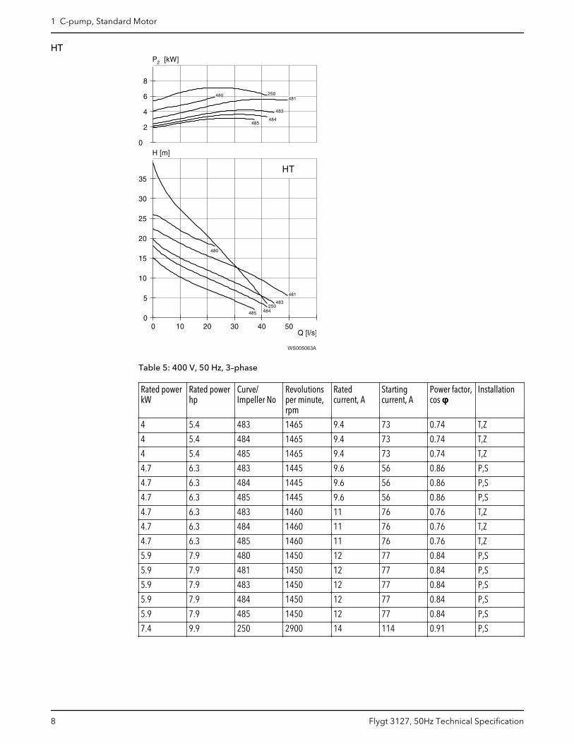
HT
WS005063A
Table 5: 400 V, 50 Hz, 3–phase
Rated powerkW
Rated powerhp
Curve/Impeller No
Revolutionsper minute,rpm
Ratedcurrent, A
Startingcurrent, A
Power factor,cos φ
Installation
4 5.4 483 1465 9.4 73 0.74 T,Z
4 5.4 484 1465 9.4 73 0.74 T,Z
4 5.4 485 1465 9.4 73 0.74 T,Z
4.7 6.3 483 1445 9.6 56 0.86 P,S
4.7 6.3 484 1445 9.6 56 0.86 P,S
4.7 6.3 485 1445 9.6 56 0.86 P,S
4.7 6.3 483 1460 11 76 0.76 T,Z
4.7 6.3 484 1460 11 76 0.76 T,Z
4.7 6.3 485 1460 11 76 0.76 T,Z
5.9 7.9 480 1450 12 77 0.84 P,S
5.9 7.9 481 1450 12 77 0.84 P,S
5.9 7.9 483 1450 12 77 0.84 P,S
5.9 7.9 484 1450 12 77 0.84 P,S
5.9 7.9 485 1450 12 77 0.84 P,S
7.4 9.9 250 2900 14 114 0.91 P,S
1 C-pump, Standard Motor
8 Flygt 3127, 50Hz Technical Specification

2 C-pump, Premium EfficiencyMotor (IE3)2.1 Product description
Usage
A submersible pump for wastewater containing solids or fibered material, clean water, orsurface water.
Denomination
Type Non-explosion proofversion
Explosion proofversion
Pressure class Installation types
Gray iron 3127.800 3127.810 LT — Low headMT — Medium headHT — High head
P, S, T, Z
Installation types
The pump can be used in the following installations:
P Semi permanent, wet well arrangement with pump installed on two guide bars withautomatic connection to discharge.
S Portable semi permanent, wet well arrangement with hose coupling or flange forconnection to discharge pipeline.
T Vertical permanent, dry well arrangement with flange connection to suction anddischarge piping.
Z Horizontal permanent, dry well arrangement with flange connection to suction anddischarge piping.
Application limits
Feature Description
Liquid temperature Maximum 40°C (104°F)
Depth of immersion Maximum 20 m (65 ft)
pH of the pumped liquid 5.5 – 14
Liquid density Maximum 1100 kg/m3
2 C-pump, Premium Efficiency Motor (IE3)
Flygt 3127, 50Hz Technical Specification 9
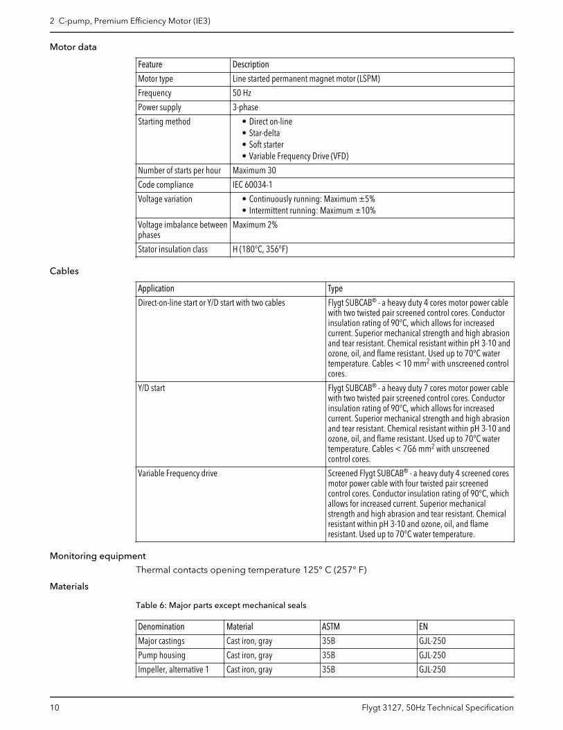
Motor data
Feature Description
Motor type Line started permanent magnet motor (LSPM)
Frequency 50 Hz
Power supply 3-phase
Starting method • Direct on-line• Star-delta• Soft starter• Variable Frequency Drive (VFD)
Number of starts per hour Maximum 30
Code compliance IEC 60034-1
Voltage variation • Continuously running: Maximum ±5%• Intermittent running: Maximum ±10%
Voltage imbalance betweenphases
Maximum 2%
Stator insulation class H (180°C, 356°F)
Cables
Application Type
Direct-on-line start or Y/D start with two cables Flygt SUBCAB® - a heavy duty 4 cores motor power cablewith two twisted pair screened control cores. Conductorinsulation rating of 90°C, which allows for increasedcurrent. Superior mechanical strength and high abrasionand tear resistant. Chemical resistant within pH 3-10 andozone, oil, and flame resistant. Used up to 70°C watertemperature. Cables < 10 mm2 with unscreened controlcores.
Y/D start Flygt SUBCAB® - a heavy duty 7 cores motor power cablewith two twisted pair screened control cores. Conductorinsulation rating of 90°C, which allows for increasedcurrent. Superior mechanical strength and high abrasionand tear resistant. Chemical resistant within pH 3-10 andozone, oil, and flame resistant. Used up to 70°C watertemperature. Cables < 7G6 mm2 with unscreenedcontrol cores.
Variable Frequency drive Screened Flygt SUBCAB® - a heavy duty 4 screened coresmotor power cable with four twisted pair screenedcontrol cores. Conductor insulation rating of 90°C, whichallows for increased current. Superior mechanicalstrength and high abrasion and tear resistant. Chemicalresistant within pH 3-10 and ozone, oil, and flameresistant. Used up to 70°C water temperature.
Monitoring equipment
Thermal contacts opening temperature 125° C (257° F)
Materials
Table 6: Major parts except mechanical seals
Denomination Material ASTM EN
Major castings Cast iron, gray 35B GJL-250
Pump housing Cast iron, gray 35B GJL-250
Impeller, alternative 1 Cast iron, gray 35B GJL-250
2 C-pump, Premium Efficiency Motor (IE3)
10 Flygt 3127, 50Hz Technical Specification
Denomination Material ASTM EN
Impeller, alternative 2 Cast iron, gray 30B GJL-200
Wear ring, alternative 1 Nitrile rubber (NBR) - -
Wear ring, alternative 2 Bronze C924 CC491K, CC492K
Lifting handle Stainless steel AISI 316L 1.4404,1.4432, …
Shaft Stainless steel AISI 431 1.4057+QT800
Screws and nuts Stainless steel, A4 AISI 316L, 316, 316Ti 1.4401,1.4404, …
O-rings, alternative 1 Nitrile rubber (NBR) 70° IRH - -
O-rings, alternative 2Fluorinated rubber (FPM)70° IRH - -
Oil, part no 901752
Medical white oil of paraffintype. Fulfills FDA 172.878(a) - -
Table 7: Mechanical seals
Alternative Inner seal Outer seal
1 Aluminum oxide/ Corrosion resistantcemented carbide
Corrosion resistant cementedcarbide/ Corrosion resistantcemented carbide
2 Corrosion resistant cementedcarbide/ Corrosion resistantcemented carbide
Corrosion resistant cementedcarbide/ Corrosion resistantcemented carbide
3 Corrosion resistant cementedcarbide/ Corrosion resistantcemented carbide
Silicon carbide/ Silicon carbide
Surface treatment
Priming Finish
Painted with a primer, see internal standardM0700.00.0002
Navy gray color NCS 5804-B07G. Two-component high-solid top coating, see internal standard M0700.00.0004for standard painting and M0700.00.0008 for specialpainting.
Options
• Leakage sensor in the stator housing (FLS)• Leakage sensor in the oil housing (CLS)• Surface treatment (Epoxy)• Zinc anodes• Other cables
Accessories
Discharge connections, adapters, hose connections, and other mechanical accessories.
Electrical accessories such as pump controller, control panels, starters, monitoring relays,cables.
2.2 Motor rating and performance curvesThese are examples of motor rating and curves. For more information, please contactyour local sales and service representative.
Star-delta starting current is 1/3 of Direct on-line starting current.
2 C-pump, Premium Efficiency Motor (IE3)
Flygt 3127, 50Hz Technical Specification 11
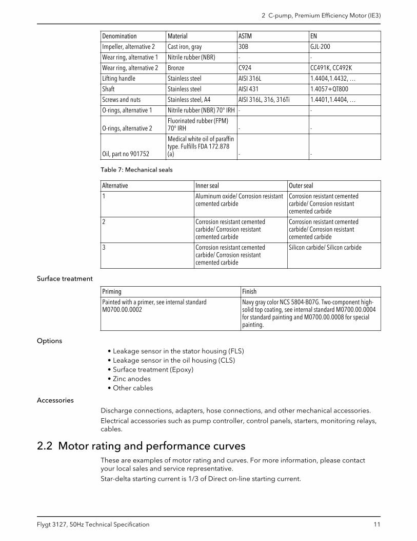
LT
Q [l/s]
H [m]
2P [kW]
0 10 20 30 40 50 60 70 80 900
2
4
6
8
10
12
2
3
4
5
LT
411
411
411
411
411
411
412
412
412
412
412
442
442
442
442
442
442
WS004724A
Table 8: 400 V, 50 Hz, 3–phase
Rated power,kW
Rated power,hp
Curve/Impeller No
Revolutionsper minute,rpm
Ratedcurrent, A
Startingcurrent, A
Power factor,cos φ
Installation
5 6.7 411 1500 8.9 76 0.89 P,S
5 6.7 412 1500 8.9 76 0.89 P,S
5 6.7 442 1500 8.9 76 0.89 P,S
5.5 7.4 411 1500 9.6 76 0.9 T,Z
5.5 7.4 412 1500 9.6 76 0.9 T,Z
5.5 7.4 442 1500 9.6 76 0.9 T,Z
6.5 8.7 411 1500 11 76 0.91 P,S
6.5 8.7 412 1500 11 76 0.91 P,S
6.5 8.7 442 1500 11 76 0.91 P,S
2 C-pump, Premium Efficiency Motor (IE3)
12 Flygt 3127, 50Hz Technical Specification
MT
Q [l/s]
H [m]
2P [kW]
0 10 20 30 40 50 600
2
4
6
8
10
12
14
16
2
3
4
5
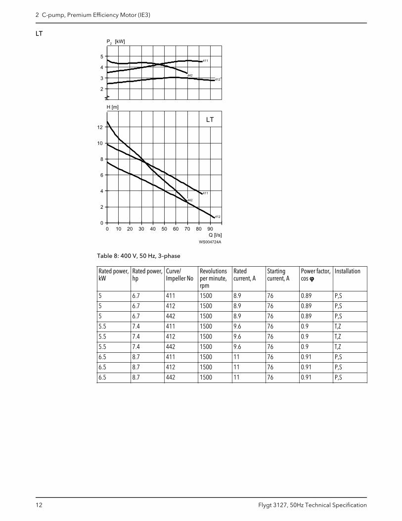
MT
431
431
431431432
432
433
433
434
434
WS004725A
Table 9: 400 V, 50 Hz, 3–phase
Rated power,kW
Rated power,hp
Curve/Impeller No
Revolutionsper minute,rpm
Ratedcurrent, A
Startingcurrent, A
Power factor,cos φ
Installation
5 6.7 431 1500 8.9 76 0.89 P,S
5 6.7 432 1500 8.9 76 0.89 P,S
5 6.7 433 1500 8.9 76 0.89 P,S
5 6.7 434 1500 8.9 76 0.89 P,S
5.5 7.4 431 1500 9.6 76 0.9 T,Z
5.5 7.4 432 1500 9.6 76 0.9 T,Z
5.5 7.4 433 1500 9.6 76 0.9 T,Z
5.5 7.4 434 1500 9.6 76 0.9 T,Z
6.5 8.7 431 1500 11 76 0.91 P,S
6.5 8.7 432 1500 11 76 0.91 P,S
6.5 8.7 433 1500 11 76 0.91 P,S
6.5 8.7 434 1500 11 76 0.91 P,S
2 C-pump, Premium Efficiency Motor (IE3)
Flygt 3127, 50Hz Technical Specification 13
HT
Q [l/s]
H [m]
2P [kW]
0 5 10 15 20 25 30 35 40 450
4
8
12
16
20
2
3
4
5
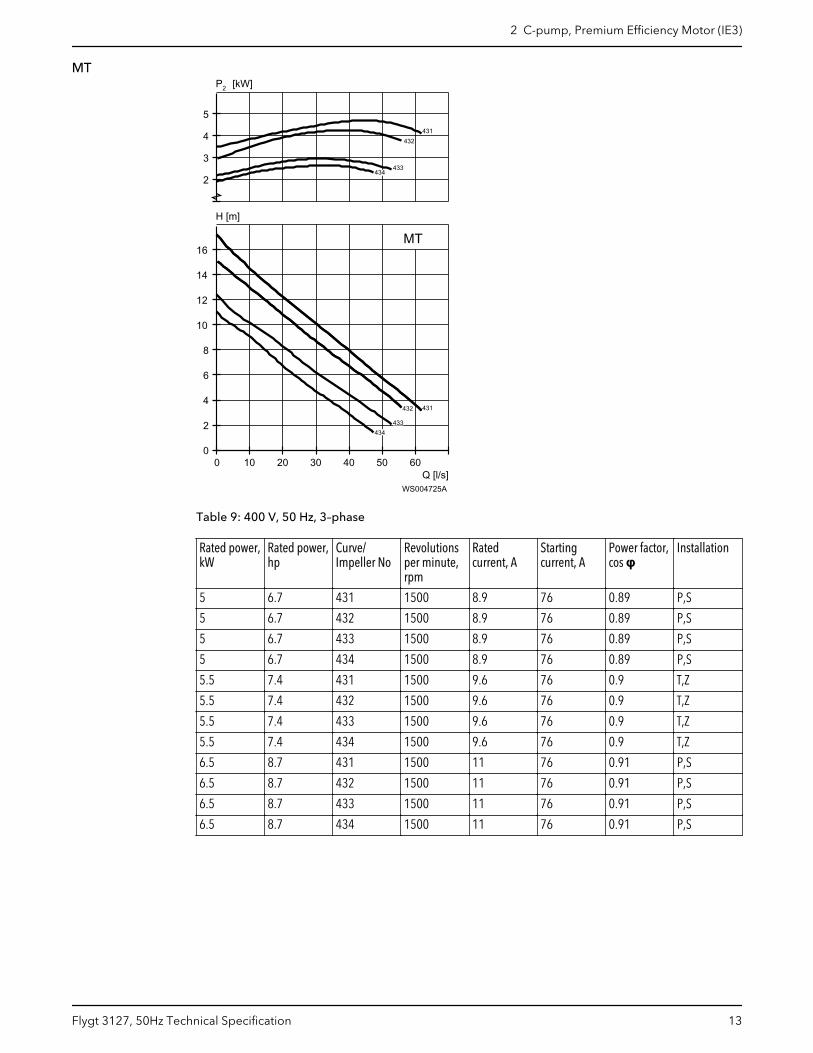
HT
483
483
484
484
485
485
WS004726A
Table 10: 400 V, 50 Hz, 3–phase
Rated power,kW
Rated power,hp
Curve/Impeller No
Revolutionsper minute,rpm
Ratedcurrent, A
Startingcurrent, A
Power factor,cos φ
Installation
5 6.7 483 1500 8.9 76 0.89 P,S
5 6.7 484 1500 8.9 76 0.89 P,S
5 6.7 485 1500 8.9 76 0.89 P,S
5.5 7.4 483 1500 9.6 76 0.9 T,Z
5.5 7.4 484 1500 9.6 76 0.9 T,Z
5.5 7.4 485 1500 9.6 76 0.9 T,Z
6.5 8.7 483 1500 11 76 0.91 P,S
6.5 8.7 484 1500 11 76 0.91 P,S
6.5 8.7 485 1500 11 76 0.91 P,S
2 C-pump, Premium Efficiency Motor (IE3)
14 Flygt 3127, 50Hz Technical Specification

3 D-pump3.1 Product description
Usage
A submersible pump, with vortex hydraulic, for liquids containing solids and abrasivemedia, or light wastewater.
Denomination
Type Non-explosion proofversion
Explosion proofversion
Pressure class Installation types
Gray iron 3127.182 3127.091 • MT — Mediumhead
• HT — High head
P
The pump can be used in the following installations:
P Semi permanent, wet well arrangement with pump installed on two guide bars withautomatic connection to discharge.
Application limits
Feature Description
Liquid temperature Maximum 40°C (104°F)
Liquid temperature, warm water version Maximum 70°C (158°F)
Depth of immersion Maximum 20 m (65 ft)
pH of the pumped liquid 5.5 – 14
Liquid density Maximum 1100 kg/m3
Motor data
Feature Description
Motor type Squirrel-cage induction motor
Frequency 50 Hz
Power supply 3-phase
Starting method • Direct on-line• Star-delta• Soft starter• Variable Frequency Drive (VFD)
3 D-pump
Flygt 3127, 50Hz Technical Specification 15
Feature Description
Number of starts per hour Maximum 30
Code compliance IEC 60034-1
Voltage variation • Continuously running: Maximum ±5%• Intermittent running: Maximum ±10%
Voltage imbalance betweenphases
Maximum 2%
Stator insulation class H (180°C, 356°F)
Cables
Application Type
Direct-on-line start or Y/D start with two cables Flygt SUBCAB® - a heavy duty 4 cores motor power cablewith two twisted pair screened control cores. Conductorinsulation rating of 90°C, which allows for increasedcurrent. Superior mechanical strength and high abrasionand tear resistant. Chemical resistant within pH 3-10 andozone, oil, and flame resistant. Used up to 70°C watertemperature. Cables < 10 mm2 with unscreened controlcores.
Y/D start Screened Flygt SUBCAB® - a heavy duty 4 screened coresmotor power cable with four twisted pair screenedcontrol cores. Conductor insulation rating of 90°C, whichallows for increased current. Superior mechanicalstrength and high abrasion and tear resistant. Chemicalresistant within pH 3-10 and ozone, oil, and flameresistant. Used up to 70°C water temperature.
Variable Frequency drive Screened Flygt SUBCAB® - a heavy duty 4 screened coresmotor power cable with four twisted pair screenedcontrol cores. Conductor insulation rating of 90°C, whichallows for increased current. Superior mechanicalstrength and high abrasion and tear resistant. Chemicalresistant within pH 3-10 and ozone, oil, and flameresistant. Used up to 70°C water temperature.
Monitoring equipment
Thermal contacts opening temperature 125° C (257° F)
Materials
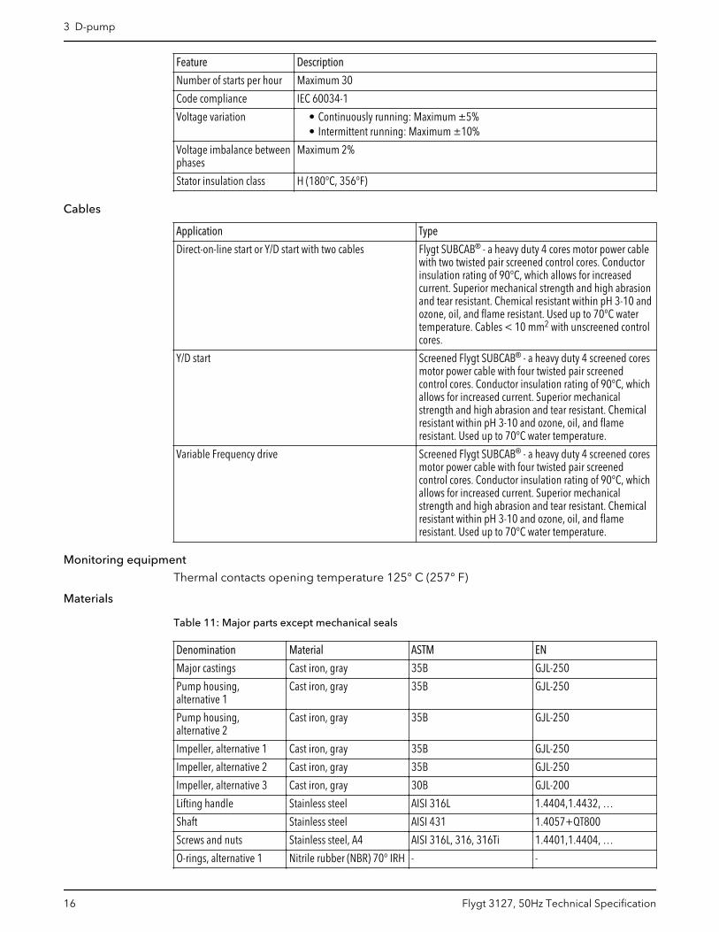
Table 11: Major parts except mechanical seals
Denomination Material ASTM EN
Major castings Cast iron, gray 35B GJL-250
Pump housing,alternative 1
Cast iron, gray 35B GJL-250
Pump housing,alternative 2
Cast iron, gray 35B GJL-250
Impeller, alternative 1 Cast iron, gray 35B GJL-250
Impeller, alternative 2 Cast iron, gray 35B GJL-250
Impeller, alternative 3 Cast iron, gray 30B GJL-200
Lifting handle Stainless steel AISI 316L 1.4404,1.4432, …
Shaft Stainless steel AISI 431 1.4057+QT800
Screws and nuts Stainless steel, A4 AISI 316L, 316, 316Ti 1.4401,1.4404, …
O-rings, alternative 1 Nitrile rubber (NBR) 70° IRH - -
3 D-pump
16 Flygt 3127, 50Hz Technical Specification
Denomination Material ASTM EN
O-rings, alternative 2 Fluorinated rubber (FPM)70° IRH
- -
Oil, part no 901752 Medical white oil of paraffintype. Fulfills FDA 172.878(a)
- -
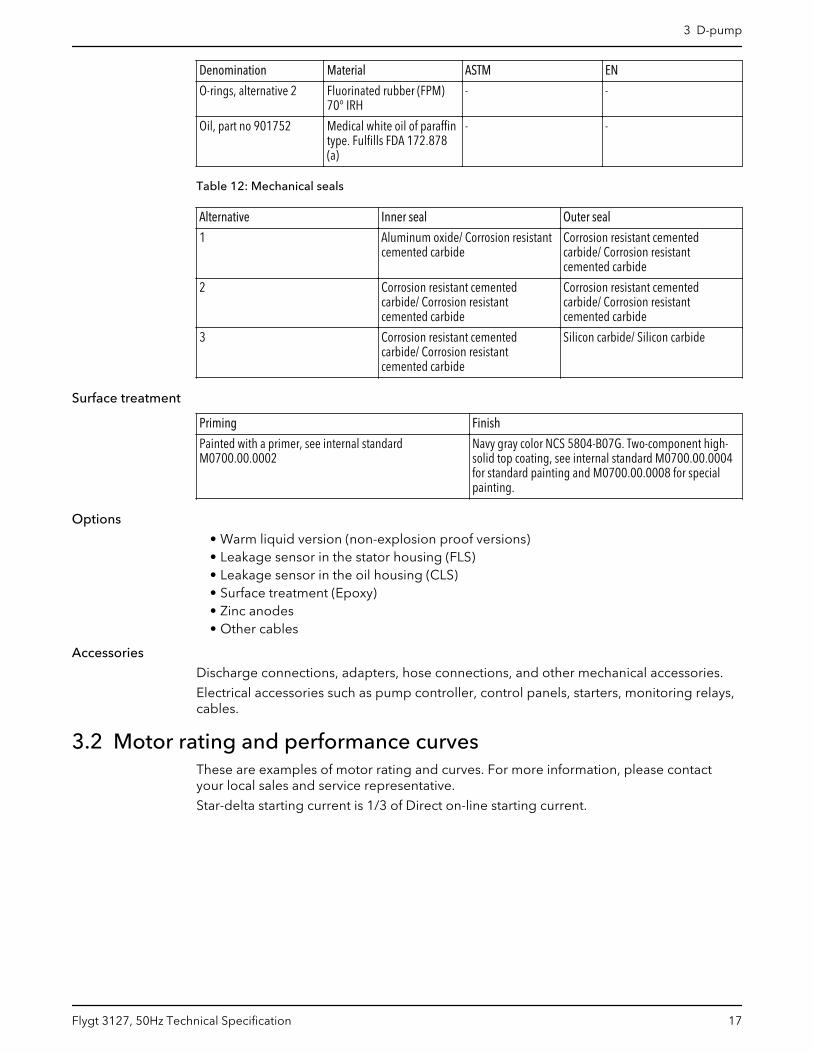
Table 12: Mechanical seals
Alternative Inner seal Outer seal
1 Aluminum oxide/ Corrosion resistantcemented carbide
Corrosion resistant cementedcarbide/ Corrosion resistantcemented carbide
2 Corrosion resistant cementedcarbide/ Corrosion resistantcemented carbide
Corrosion resistant cementedcarbide/ Corrosion resistantcemented carbide
3 Corrosion resistant cementedcarbide/ Corrosion resistantcemented carbide
Silicon carbide/ Silicon carbide
Surface treatment
Priming Finish
Painted with a primer, see internal standardM0700.00.0002
Navy gray color NCS 5804-B07G. Two-component high-solid top coating, see internal standard M0700.00.0004for standard painting and M0700.00.0008 for specialpainting.
Options
• Warm liquid version (non-explosion proof versions)• Leakage sensor in the stator housing (FLS)• Leakage sensor in the oil housing (CLS)• Surface treatment (Epoxy)• Zinc anodes• Other cables
Accessories
Discharge connections, adapters, hose connections, and other mechanical accessories.
Electrical accessories such as pump controller, control panels, starters, monitoring relays,cables.
3.2 Motor rating and performance curvesThese are examples of motor rating and curves. For more information, please contactyour local sales and service representative.
Star-delta starting current is 1/3 of Direct on-line starting current.
3 D-pump
Flygt 3127, 50Hz Technical Specification 17
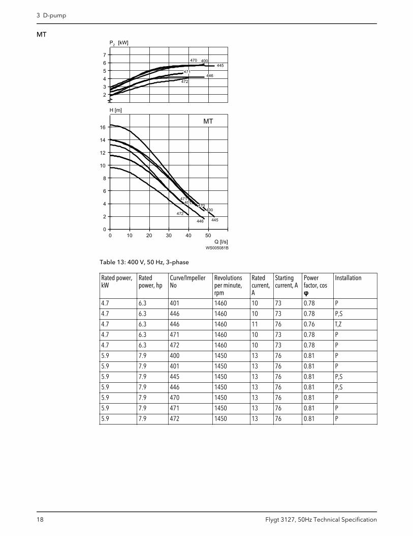
MT
Q [l/s]
H [m]
2P [kW]
0 10 20 30 40 500
2
4
6
8
10
12
14
16
234567
MT
400
400
401
401
445
445
446
446
470
470
471
471
472
472
WS005081B
Table 13: 400 V, 50 Hz, 3–phase
Rated power,kW
Ratedpower, hp
Curve/ImpellerNo
Revolutionsper minute,rpm
Ratedcurrent,A
Startingcurrent, A
Powerfactor, cosφ
Installation
4.7 6.3 401 1460 10 73 0.78 P
4.7 6.3 446 1460 10 73 0.78 P,S
4.7 6.3 446 1460 11 76 0.76 T,Z
4.7 6.3 471 1460 10 73 0.78 P
4.7 6.3 472 1460 10 73 0.78 P
5.9 7.9 400 1450 13 76 0.81 P
5.9 7.9 401 1450 13 76 0.81 P
5.9 7.9 445 1450 13 76 0.81 P,S
5.9 7.9 446 1450 13 76 0.81 P,S
5.9 7.9 470 1450 13 76 0.81 P
5.9 7.9 471 1450 13 76 0.81 P
5.9 7.9 472 1450 13 76 0.81 P
3 D-pump
18 Flygt 3127, 50Hz Technical Specification
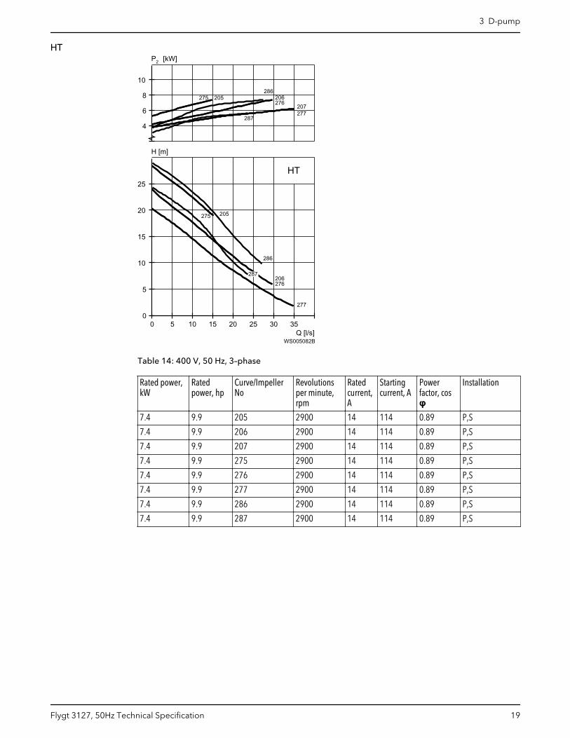
HT
Q [l/s]
H [m]
2P [kW]
0 5 10 15 20 25 30 350
5
10
15
20
25
4
6
8
10
HT
205
205
206
206
207
207
275
275
276
276
277
277
286
286
287
287
WS005082B
Table 14: 400 V, 50 Hz, 3–phase
Rated power,kW
Ratedpower, hp
Curve/ImpellerNo
Revolutionsper minute,rpm
Ratedcurrent,A
Startingcurrent, A
Powerfactor, cosφ
Installation
7.4 9.9 205 2900 14 114 0.89 P,S
7.4 9.9 206 2900 14 114 0.89 P,S
7.4 9.9 207 2900 14 114 0.89 P,S
7.4 9.9 275 2900 14 114 0.89 P,S
7.4 9.9 276 2900 14 114 0.89 P,S
7.4 9.9 277 2900 14 114 0.89 P,S
7.4 9.9 286 2900 14 114 0.89 P,S
7.4 9.9 287 2900 14 114 0.89 P,S
3 D-pump
Flygt 3127, 50Hz Technical Specification 19
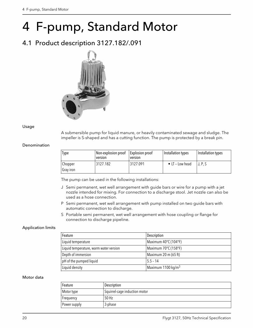
4 F-pump, Standard Motor4.1 Product description 3127.182/.091
Usage
A submersible pump for liquid manure, or heavily contaminated sewage and sludge. Theimpeller is S-shaped and has a cutting function. The pump is protected by a break pin.
Denomination
Type Non-explosion proofversion
Explosion proofversion
Installation types Installation types
ChopperGray iron
3127.182 3127.091 • LT — Low head J, P, S
The pump can be used in the following installations:
J Semi permanent, wet well arrangement with guide bars or wire for a pump with a jetnozzle intended for mixing. For connection to a discharge stool. Jet nozzle can also beused as a hose connection.
P Semi permanent, wet well arrangement with pump installed on two guide bars withautomatic connection to discharge.
S Portable semi permanent, wet well arrangement with hose coupling or flange forconnection to discharge pipeline.
Application limits
Feature Description
Liquid temperature Maximum 40°C (104°F)
Liquid temperature, warm water version Maximum 70°C (158°F)
Depth of immersion Maximum 20 m (65 ft)
pH of the pumped liquid 5.5 – 14
Liquid density Maximum 1100 kg/m3
Motor data
Feature Description
Motor type Squirrel-cage induction motor
Frequency 50 Hz
Power supply 3-phase
4 F-pump, Standard Motor
20 Flygt 3127, 50Hz Technical Specification
Feature Description
Starting method • Direct on-line• Star-delta• Soft starter• Variable Frequency Drive (VFD)
Number of starts per hour Maximum 30
Code compliance IEC 60034-1
Voltage variation • Continuously running: Maximum ±5%• Intermittent running: Maximum ±10%
Voltage imbalance betweenphases
Maximum 2%
Stator insulation class H (180°C, 356°F)
Cables
Application Type
Direct-on-line start or Y/D start with two cables Flygt SUBCAB® - a heavy duty 4 cores motor power cablewith two twisted pair screened control cores. Conductorinsulation rating of 90°C, which allows for increasedcurrent. Superior mechanical strength and high abrasionand tear resistant. Chemical resistant within pH 3-10 andozone, oil, and flame resistant. Used up to 70°C watertemperature. Cables < 10 mm2 with unscreened controlcores.
Y/D start Flygt SUBCAB® - a heavy duty 7 cores motor power cablewith two twisted pair screened control cores. Conductorinsulation rating of 90°C, which allows for increasedcurrent. Superior mechanical strength and high abrasionand tear resistant. Chemical resistant within pH 3-10 andozone, oil, and flame resistant. Used up to 70°C watertemperature. Cables < 7G6 mm2 with unscreenedcontrol cores.
Variable Frequency drive Screened Flygt SUBCAB® - a heavy duty 4 screened coresmotor power cable with four twisted pair screenedcontrol cores. Conductor insulation rating of 90°C, whichallows for increased current. Superior mechanicalstrength and high abrasion and tear resistant. Chemicalresistant within pH 3-10 and ozone, oil, and flameresistant. Used up to 70°C water temperature.
Monitoring equipment
Thermal contacts opening temperature 125° C (257° F)
Materials
Table 15: Major parts except mechanical seals
Denomination Material ASTM EN
Major castings Cast iron, gray 35B GJL-250
Pump housing Cast iron, gray 35B GJL-250
Impeller Cast iron, nodular - GJS-400-18-LT
Suction cover, alternative1
Cast iron, Hard-Iron™ A 532 IIIA GJN-HB555(XCR23)
Suction cover, alternative2
Steel A 572 GR50 S355
4 F-pump, Standard Motor
Flygt 3127, 50Hz Technical Specification 21
Denomination Material ASTM EN
Suction cover, alternative3
Cast iron, Hard-Iron™ A 532 IIIA GJN-HB555(XCR23)
Lifting handle Stainless steel AISI 316L 1.4404,1.4432, …
Shaft Stainless steel AISI 431 1.4057+QT800
Screws and nuts Stainless steel, A4 AISI 316L, 316, 316Ti 1.4401,1.4404, …
O-rings, alternative 1 Nitrile rubber (NBR) 70° IRH - -
O-rings, alternative 2 Fluorinated rubber (FPM)70° IRH
- -
Oil, part no 901752 Medical white oil of paraffintype. Fulfills FDA 172.878(a)
- -
Table 16: Mechanical seals
Alternative Inner seal Outer seal
1 Aluminum oxide/ Corrosion resistantcemented carbide
Corrosion resistant cementedcarbide/ Corrosion resistantcemented carbide
2 Corrosion resistant cementedcarbide/ Corrosion resistantcemented carbide
Corrosion resistant cementedcarbide/ Corrosion resistantcemented carbide
3 Corrosion resistant cementedcarbide/ Corrosion resistantcemented carbide
Silicon carbide/ Silicon carbide
Surface treatment
Priming Finish
Painted with a primer, see internal standardM0700.00.0002
Navy gray color NCS 5804-B07G. Two-component high-solid top coating, see internal standard M0700.00.0004for standard painting and M0700.00.0008 for specialpainting.
Options
• Warm liquid version (non-explosion proof versions)• Leakage sensor in the stator housing (FLS)• Leakage sensor in the oil housing (CLS)• Aqua cutting knife (chopper)
pressure class LT• Surface treatment (Epoxy)• Zinc anodes• Other cables
Accessories
Discharge connections, adapters, hose connections, and other mechanical accessories.
Electrical accessories such as pump controller, control panels, starters, monitoring relays,cables.
4 F-pump, Standard Motor
22 Flygt 3127, 50Hz Technical Specification
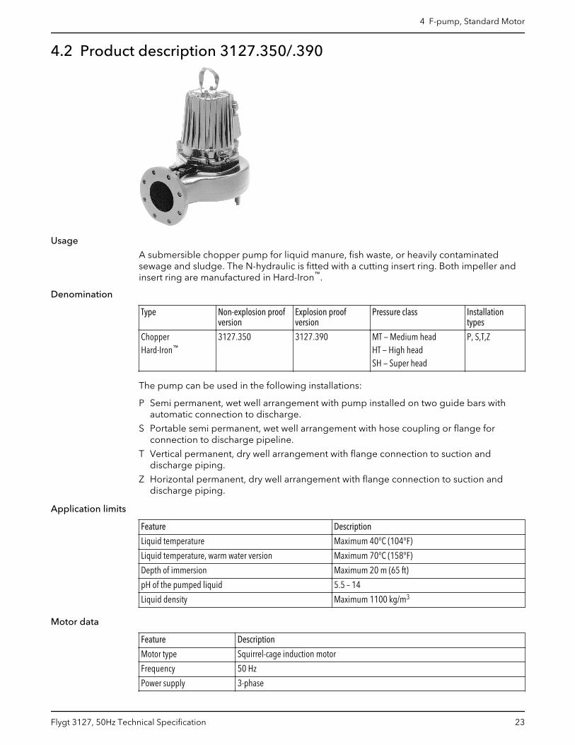
4.2 Product description 3127.350/.390
Usage
A submersible chopper pump for liquid manure, fish waste, or heavily contaminatedsewage and sludge. The N-hydraulic is fitted with a cutting insert ring. Both impeller andinsert ring are manufactured in Hard-Iron™.
Denomination
Type Non-explosion proofversion
Explosion proofversion
Pressure class Installationtypes
ChopperHard-Iron™
3127.350 3127.390 MT — Medium headHT — High headSH — Super head
P, S,T,Z
The pump can be used in the following installations:
P Semi permanent, wet well arrangement with pump installed on two guide bars withautomatic connection to discharge.
S Portable semi permanent, wet well arrangement with hose coupling or flange forconnection to discharge pipeline.
T Vertical permanent, dry well arrangement with flange connection to suction anddischarge piping.
Z Horizontal permanent, dry well arrangement with flange connection to suction anddischarge piping.
Application limits
Feature Description
Liquid temperature Maximum 40°C (104°F)
Liquid temperature, warm water version Maximum 70°C (158°F)
Depth of immersion Maximum 20 m (65 ft)
pH of the pumped liquid 5.5 – 14
Liquid density Maximum 1100 kg/m3
Motor data
Feature Description
Motor type Squirrel-cage induction motor
Frequency 50 Hz
Power supply 3-phase
4 F-pump, Standard Motor
Flygt 3127, 50Hz Technical Specification 23
Feature Description
Starting method • Direct on-line• Star-delta• Soft starter• Variable Frequency Drive (VFD)
Number of starts per hour Maximum 30
Code compliance IEC 60034-1
Voltage variation • Continuously running: Maximum ±5%• Intermittent running: Maximum ±10%
Voltage imbalance betweenphases
Maximum 2%
Stator insulation class H (180°C, 356°F)
Cables
Application Type
Direct-on-line start or Y/D start with two cables Flygt SUBCAB® - a heavy duty 4 cores motor power cablewith two twisted pair screened control cores. Conductorinsulation rating of 90°C, which allows for increasedcurrent. Superior mechanical strength and high abrasionand tear resistant. Chemical resistant within pH 3-10 andozone, oil, and flame resistant. Used up to 70°C watertemperature. Cables < 10 mm2 with unscreened controlcores.
Y/D start Flygt SUBCAB® - a heavy duty 7 cores motor power cablewith two twisted pair screened control cores. Conductorinsulation rating of 90°C, which allows for increasedcurrent. Superior mechanical strength and high abrasionand tear resistant. Chemical resistant within pH 3-10 andozone, oil, and flame resistant. Used up to 70°C watertemperature. Cables < 7G6 mm2 with unscreenedcontrol cores.
Variable Frequency drive Screened Flygt SUBCAB® - a heavy duty 4 screened coresmotor power cable with four twisted pair screened controlcores. Conductor insulation rating of 90°C, which allowsfor increased current. Superior mechanical strength andhigh abrasion and tear resistant. Chemical resistantwithin pH 3-10 and ozone, oil, and flame resistant. Usedup to 70°C water temperature.
Monitoring equipment
Thermal contacts opening temperature 125° C (257° F)
Materials
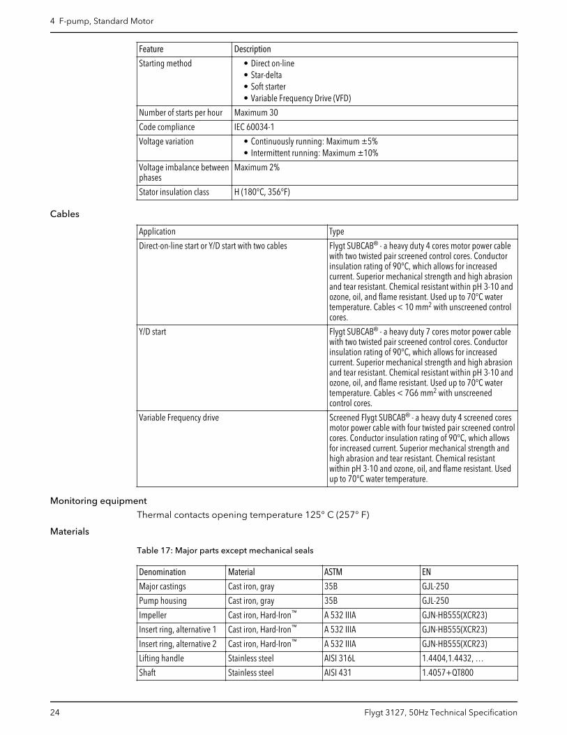
Table 17: Major parts except mechanical seals
Denomination Material ASTM EN
Major castings Cast iron, gray 35B GJL-250
Pump housing Cast iron, gray 35B GJL-250
Impeller Cast iron, Hard-Iron™ A 532 IIIA GJN-HB555(XCR23)
Insert ring, alternative 1 Cast iron, Hard-Iron™ A 532 IIIA GJN-HB555(XCR23)
Insert ring, alternative 2 Cast iron, Hard-Iron™ A 532 IIIA GJN-HB555(XCR23)
Lifting handle Stainless steel AISI 316L 1.4404,1.4432, …
Shaft Stainless steel AISI 431 1.4057+QT800
4 F-pump, Standard Motor
24 Flygt 3127, 50Hz Technical Specification
Denomination Material ASTM EN
Screws and nuts Stainless steel, A4 AISI 316L, 316, 316Ti 1.4401,1.4404, …
O-rings, alternative 1 Nitrile rubber (NBR) 70° IRH - -
O-rings, alternative 2 Fluorinated rubber (FPM)70° IRH
- -
Oil, part no 901752 Medical white oil of paraffintype. Fulfills FDA 172.878(a)
- -
Table 18: Mechanical seals
Alternative Inner seal Outer seal
1 Aluminum oxide/ Corrosion resistantcemented carbide
Corrosion resistant cementedcarbide/ Corrosion resistantcemented carbide
2 Corrosion resistant cementedcarbide/ Corrosion resistantcemented carbide
Corrosion resistant cementedcarbide/ Corrosion resistantcemented carbide
3 Corrosion resistant cementedcarbide/ Corrosion resistantcemented carbide
Silicon carbide/ Silicon carbide
Surface treatment
Priming Finish
Painted with a primer, see internal standardM0700.00.0002
Navy gray color NCS 5804-B07G. Two-component high-solid top coating, see internal standard M0700.00.0004for standard painting and M0700.00.0008 for specialpainting.
Options
• Warm liquid version (non-explosion proof versions)• Leakage sensor in the stator housing (FLS)• Leakage sensor in the oil housing (CLS)• Aqua cutting knife (chopper)
pressure class MT• Surface treatment (Epoxy)• Zinc anodes• Other cables
Accessories
Discharge connections, adapters, hose connections, and other mechanical accessories.
Electrical accessories such as pump controller, control panels, starters, monitoring relays,cables.
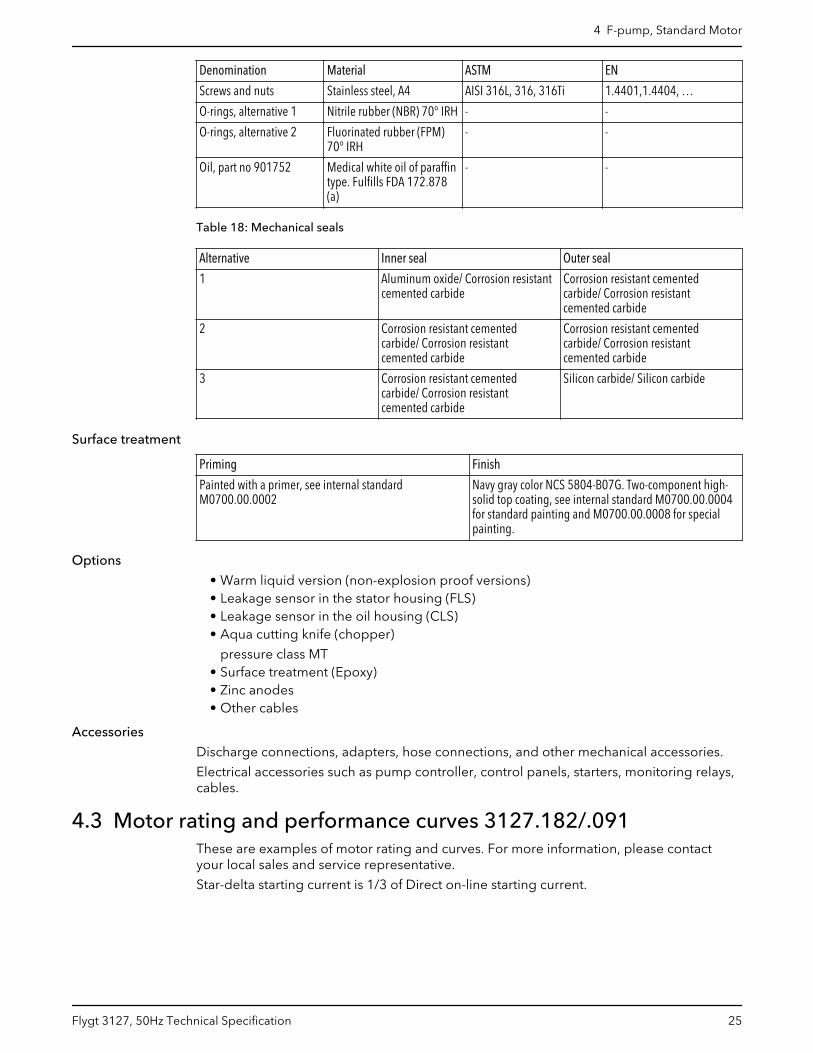
4.3 Motor rating and performance curves 3127.182/.091These are examples of motor rating and curves. For more information, please contactyour local sales and service representative.
Star-delta starting current is 1/3 of Direct on-line starting current.
4 F-pump, Standard Motor
Flygt 3127, 50Hz Technical Specification 25
LT
Q [l/s]
H [m]
2P [kW]
0 10 20 30 40 50 600
2
4
6
8
10
0123456
LT
490
490490490
491
491
491
491
491
491
491
491
491
491
491/493
491
492
492
492
492
492
492
492
492
492
492
492
492493493493493493491/493
WS005069B
Table 19: 400 V, 50 Hz, 3–phase
Rated power,kW
Rated power,hp
Curve/Impeller No
Revolutionsper minute,rpm
Ratedcurrent, A
Startingcurrent, A
Power factor,cos φ
Installation
4.7 6.3 491 1460 10 73 0.78 P,S
4.7 6.3 492 1460 10 73 0.78 P,S
5.9 7.9 490 1450 12 77 0.84 J,P,S
5.9 7.9 491 1450 12 77 0.84 P,S
5.9 7.9 492 1450 12 77 0.84 P,S
5.9 7.9 493 1450 12 77 0.84 P,S
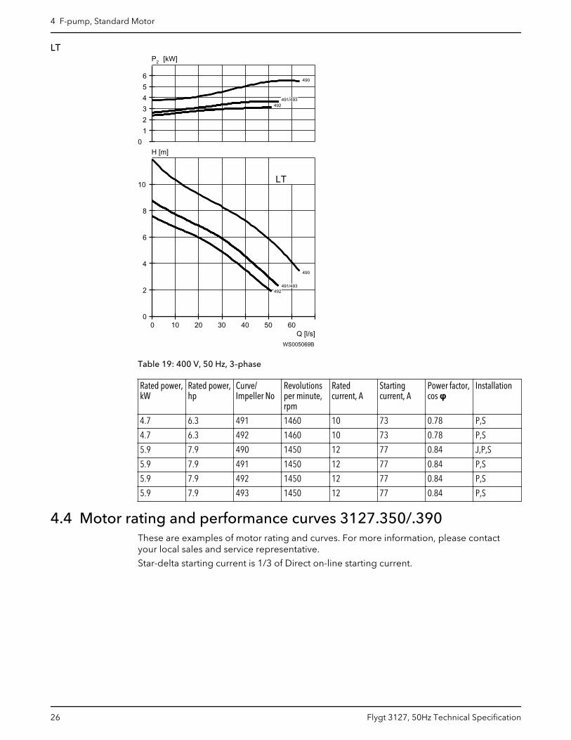
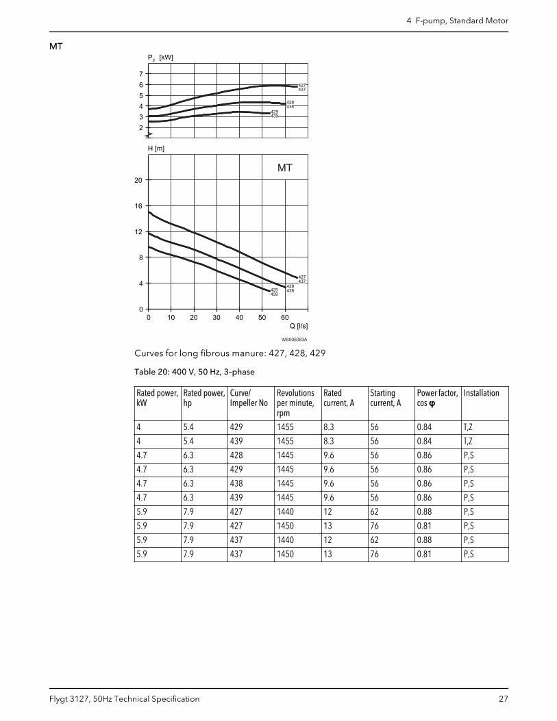
4.4 Motor rating and performance curves 3127.350/.390These are examples of motor rating and curves. For more information, please contactyour local sales and service representative.
Star-delta starting current is 1/3 of Direct on-line starting current.
4 F-pump, Standard Motor
26 Flygt 3127, 50Hz Technical Specification
MT
Q [l/s]
H [m]
2P [kW]
0 10 20 30 40 50 600
4
8
12
16
20
234567
427
427
428
428
429
429
437
437
438
438
439
439
MT
WS005083A
Curves for long fibrous manure: 427, 428, 429
Table 20: 400 V, 50 Hz, 3–phase
Rated power,kW
Rated power,hp
Curve/Impeller No
Revolutionsper minute,rpm
Ratedcurrent, A
Startingcurrent, A
Power factor,cos φ
Installation
4 5.4 429 1455 8.3 56 0.84 T,Z
4 5.4 439 1455 8.3 56 0.84 T,Z
4.7 6.3 428 1445 9.6 56 0.86 P,S
4.7 6.3 429 1445 9.6 56 0.86 P,S
4.7 6.3 438 1445 9.6 56 0.86 P,S
4.7 6.3 439 1445 9.6 56 0.86 P,S
5.9 7.9 427 1440 12 62 0.88 P,S
5.9 7.9 427 1450 13 76 0.81 P,S
5.9 7.9 437 1440 12 62 0.88 P,S
5.9 7.9 437 1450 13 76 0.81 P,S
4 F-pump, Standard Motor
Flygt 3127, 50Hz Technical Specification 27
HT
Q [l/s]
H [m]
2P [kW]
0 10 20 30 40 50 600
4
8
12
16
20
234567
477
477
478
478
479
479
487
487
488
488
489
489
HT
WS005084A
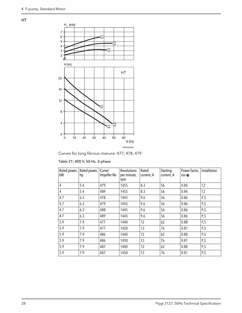
Curves for long fibrous manure: 477, 478, 479
Table 21: 400 V, 50 Hz, 3–phase
Rated power,kW
Rated power,hp
Curve/Impeller No
Revolutionsper minute,rpm
Ratedcurrent, A
Startingcurrent, A
Power factor,cos φ
Installation
4 5.4 479 1455 8.3 56 0.84 T,Z
4 5.4 489 1455 8.3 56 0.84 T,Z
4.7 6.3 478 1445 9.6 56 0.86 P,S
4.7 6.3 479 1445 9.6 56 0.86 P,S
4.7 6.3 488 1445 9.6 56 0.86 P,S
4.7 6.3 489 1445 9.6 56 0.86 P,S
5.9 7.9 477 1440 12 62 0.88 P,S
5.9 7.9 477 1450 13 76 0.81 P,S
5.9 7.9 486 1440 12 62 0.88 P,S
5.9 7.9 486 1450 13 76 0.81 P,S
5.9 7.9 487 1440 12 62 0.88 P,S
5.9 7.9 487 1450 13 76 0.81 P,S
4 F-pump, Standard Motor
28 Flygt 3127, 50Hz Technical Specification
SH
Q [l/s]
H [m]
2P [kW]
0 5 10 15 20 25 300
5
10
15
20
25
30
35
345678
SH
242242 / 247
241
242
243
241 /
242 /
246
247
248243 /
243 249244/
242242 / 247
241
242
243
241 /
242 /
246
247
248243 /
243 249244/
WS005085A
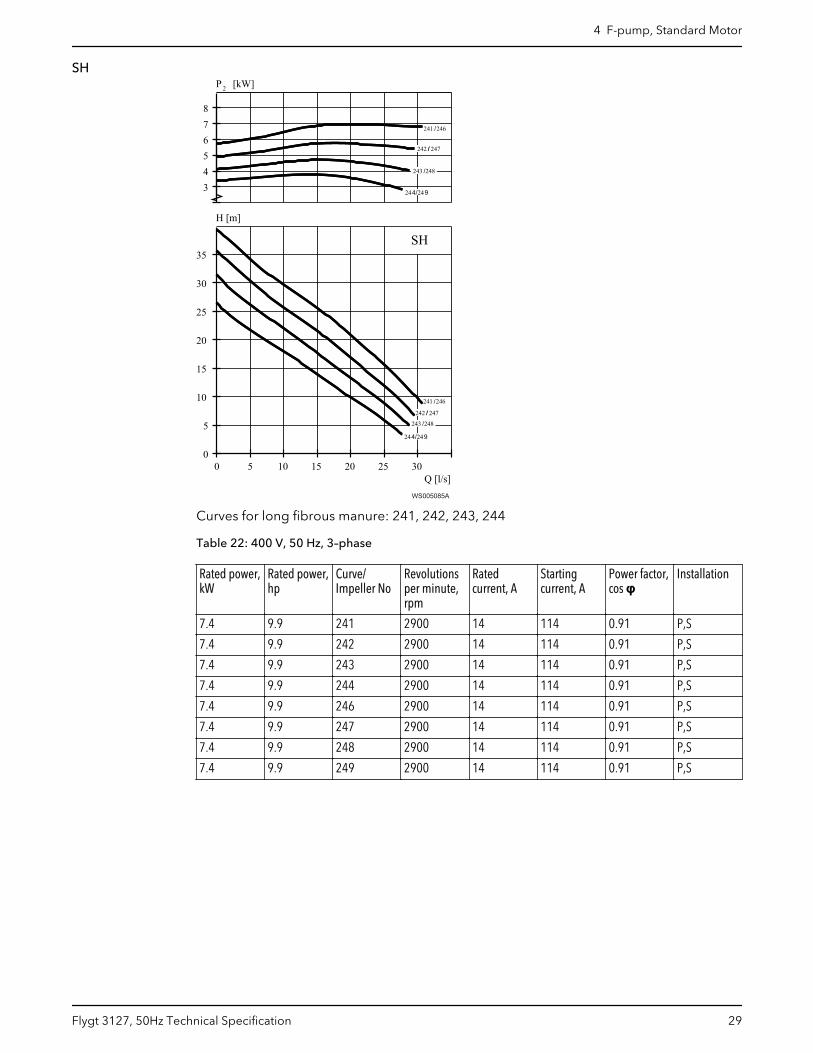
Curves for long fibrous manure: 241, 242, 243, 244
Table 22: 400 V, 50 Hz, 3–phase
Rated power,kW
Rated power,hp
Curve/Impeller No
Revolutionsper minute,rpm
Ratedcurrent, A
Startingcurrent, A
Power factor,cos φ
Installation
7.4 9.9 241 2900 14 114 0.91 P,S
7.4 9.9 242 2900 14 114 0.91 P,S
7.4 9.9 243 2900 14 114 0.91 P,S
7.4 9.9 244 2900 14 114 0.91 P,S
7.4 9.9 246 2900 14 114 0.91 P,S
7.4 9.9 247 2900 14 114 0.91 P,S
7.4 9.9 248 2900 14 114 0.91 P,S
7.4 9.9 249 2900 14 114 0.91 P,S
4 F-pump, Standard Motor
Flygt 3127, 50Hz Technical Specification 29
5 F-pump, Premium EfficiencyMotor (IE3)5.1 Product description
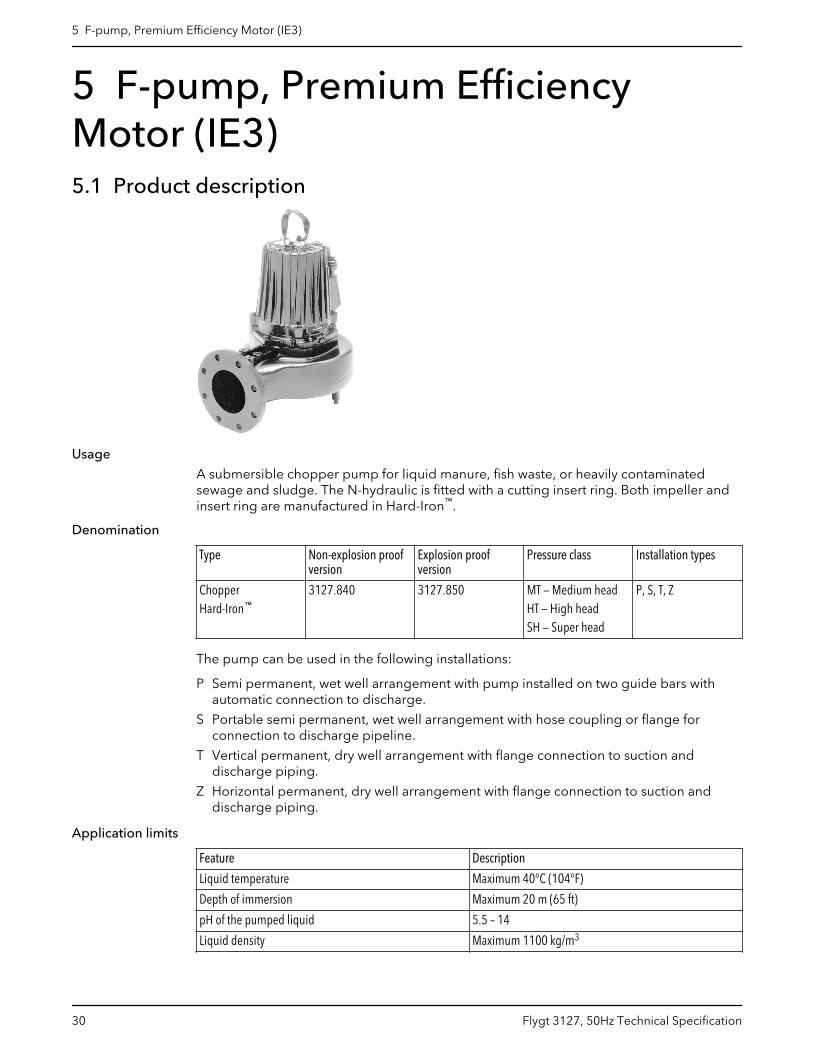
Usage
A submersible chopper pump for liquid manure, fish waste, or heavily contaminatedsewage and sludge. The N-hydraulic is fitted with a cutting insert ring. Both impeller andinsert ring are manufactured in Hard-Iron™.
Denomination
Type Non-explosion proofversion
Explosion proofversion
Pressure class Installation types
ChopperHard-Iron™
3127.840 3127.850 MT — Medium headHT — High headSH — Super head
P, S, T, Z
The pump can be used in the following installations:
P Semi permanent, wet well arrangement with pump installed on two guide bars withautomatic connection to discharge.
S Portable semi permanent, wet well arrangement with hose coupling or flange forconnection to discharge pipeline.
T Vertical permanent, dry well arrangement with flange connection to suction anddischarge piping.
Z Horizontal permanent, dry well arrangement with flange connection to suction anddischarge piping.
Application limits
Feature Description
Liquid temperature Maximum 40°C (104°F)
Depth of immersion Maximum 20 m (65 ft)
pH of the pumped liquid 5.5 – 14
Liquid density Maximum 1100 kg/m3
5 F-pump, Premium Efficiency Motor (IE3)
30 Flygt 3127, 50Hz Technical Specification
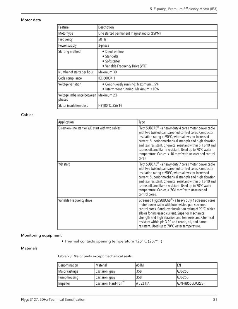
Motor data
Feature Description
Motor type Line started permanent magnet motor (LSPM)
Frequency 50 Hz
Power supply 3-phase
Starting method • Direct on-line• Star-delta• Soft starter• Variable Frequency Drive (VFD)
Number of starts per hour Maximum 30
Code compliance IEC 60034-1
Voltage variation • Continuously running: Maximum ±5%• Intermittent running: Maximum ±10%
Voltage imbalance betweenphases
Maximum 2%
Stator insulation class H (180°C, 356°F)
Cables
Application Type
Direct-on-line start or Y/D start with two cables Flygt SUBCAB® - a heavy duty 4 cores motor power cablewith two twisted pair screened control cores. Conductorinsulation rating of 90°C, which allows for increasedcurrent. Superior mechanical strength and high abrasionand tear resistant. Chemical resistant within pH 3-10 andozone, oil, and flame resistant. Used up to 70°C watertemperature. Cables < 10 mm2 with unscreened controlcores.
Y/D start Flygt SUBCAB® - a heavy duty 7 cores motor power cablewith two twisted pair screened control cores. Conductorinsulation rating of 90°C, which allows for increasedcurrent. Superior mechanical strength and high abrasionand tear resistant. Chemical resistant within pH 3-10 andozone, oil, and flame resistant. Used up to 70°C watertemperature. Cables < 7G6 mm2 with unscreenedcontrol cores.
Variable Frequency drive Screened Flygt SUBCAB® - a heavy duty 4 screened coresmotor power cable with four twisted pair screenedcontrol cores. Conductor insulation rating of 90°C, whichallows for increased current. Superior mechanicalstrength and high abrasion and tear resistant. Chemicalresistant within pH 3-10 and ozone, oil, and flameresistant. Used up to 70°C water temperature.
Monitoring equipment
• Thermal contacts opening temperature 125° C (257° F)
Materials
Table 23: Major parts except mechanical seals
Denomination Material ASTM EN
Major castings Cast iron, gray 35B GJL-250
Pump housing Cast iron, gray 35B GJL-250
Impeller Cast iron, Hard-Iron™ A 532 IIIA GJN-HB555(XCR23)
5 F-pump, Premium Efficiency Motor (IE3)
Flygt 3127, 50Hz Technical Specification 31
Denomination Material ASTM EN
Insert ring, alternative 1 Cast iron, Hard-Iron™ A 532 IIIA GJN-HB555(XCR23)
Insert ring, alternative 2 Cast iron, Hard-Iron™ A 532 IIIA GJN-HB555(XCR23)
Lifting handle Stainless steel AISI 316L 1.4404,1.4432, …
Shaft Stainless steel AISI 431 1.4057+QT800
Screws and nuts Stainless steel, A4 AISI 316L, 316, 316Ti 1.4401,1.4404, …
O-rings, alternative 1 Nitrile rubber (NBR) 70° IRH - -
O-rings, alternative 2Fluorinated rubber (FPM)70° IRH - -
Oil, part no 901752
Medical white oil of paraffintype. Fulfills FDA 172.878(a) - -
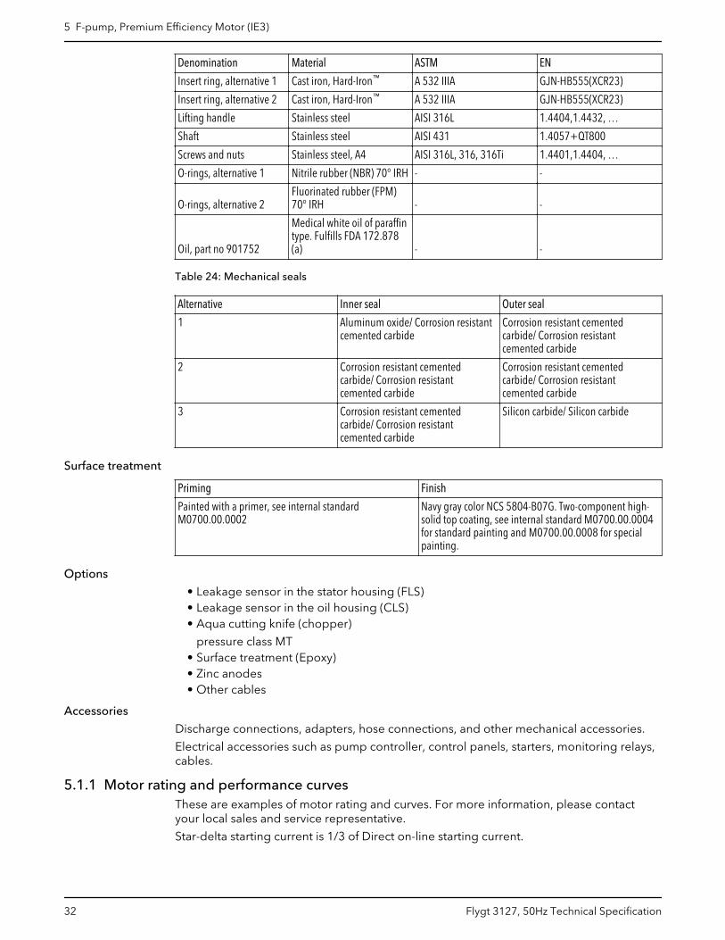
Table 24: Mechanical seals
Alternative Inner seal Outer seal
1 Aluminum oxide/ Corrosion resistantcemented carbide
Corrosion resistant cementedcarbide/ Corrosion resistantcemented carbide
2 Corrosion resistant cementedcarbide/ Corrosion resistantcemented carbide
Corrosion resistant cementedcarbide/ Corrosion resistantcemented carbide
3 Corrosion resistant cementedcarbide/ Corrosion resistantcemented carbide
Silicon carbide/ Silicon carbide
Surface treatment
Priming Finish
Painted with a primer, see internal standardM0700.00.0002
Navy gray color NCS 5804-B07G. Two-component high-solid top coating, see internal standard M0700.00.0004for standard painting and M0700.00.0008 for specialpainting.
Options
• Leakage sensor in the stator housing (FLS)• Leakage sensor in the oil housing (CLS)• Aqua cutting knife (chopper)
pressure class MT• Surface treatment (Epoxy)• Zinc anodes• Other cables
Accessories
Discharge connections, adapters, hose connections, and other mechanical accessories.
Electrical accessories such as pump controller, control panels, starters, monitoring relays,cables.
5.1.1 Motor rating and performance curvesThese are examples of motor rating and curves. For more information, please contactyour local sales and service representative.
Star-delta starting current is 1/3 of Direct on-line starting current.
5 F-pump, Premium Efficiency Motor (IE3)
32 Flygt 3127, 50Hz Technical Specification
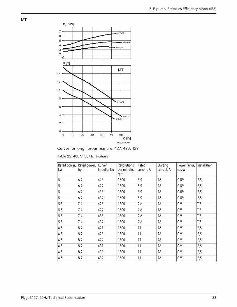
MT
Q [l/s]
H [m]
2P [kW]
0 10 20 30 40 50 600
2
4
6
8
10
12
14
234567
MT
427/437
427/437
428/438
428/438
429/439
429/439
WS004730A
Curves for long fibrous manure: 427, 428, 429
Table 25: 400 V, 50 Hz, 3–phase
Rated power,kW
Rated power,hp
Curve/Impeller No
Revolutionsper minute,rpm
Ratedcurrent, A
Startingcurrent, A
Power factor,cos φ
Installation
5 6.7 428 1500 8.9 76 0.89 P,S
5 6.7 429 1500 8.9 76 0.89 P,S
5 6.7 438 1500 8.9 76 0.89 P,S
5 6.7 439 1500 8.9 76 0.89 P,S
5.5 7.4 428 1500 9.6 76 0.9 T,Z
5.5 7.4 429 1500 9.6 76 0.9 T,Z
5.5 7.4 438 1500 9.6 76 0.9 T,Z
5.5 7.4 439 1500 9.6 76 0.9 T,Z
6.5 8.7 427 1500 11 76 0.91 P,S
6.5 8.7 428 1500 11 76 0.91 P,S
6.5 8.7 429 1500 11 76 0.91 P,S
6.5 8.7 437 1500 11 76 0.91 P,S
6.5 8.7 438 1500 11 76 0.91 P,S
6.5 8.7 439 1500 11 76 0.91 P,S
5 F-pump, Premium Efficiency Motor (IE3)
Flygt 3127, 50Hz Technical Specification 33
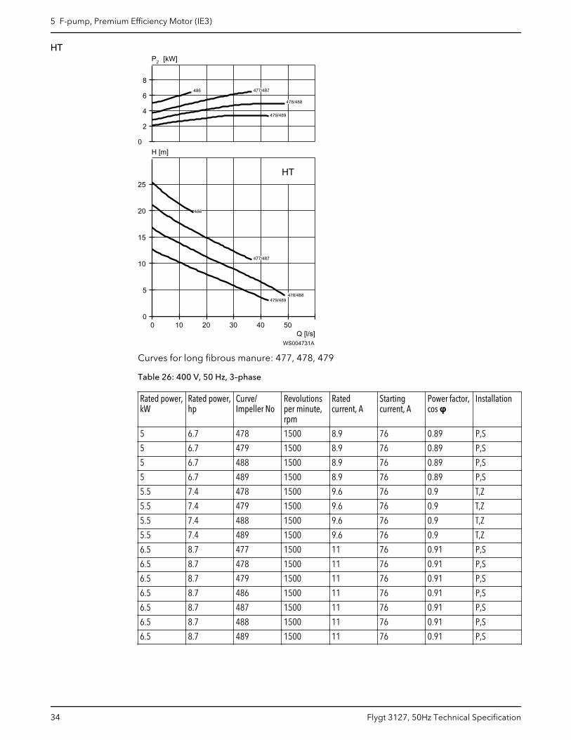
HT
Q [l/s]
H [m]
2P [kW]
0 10 20 30 40 500
5
10
15
20
25
0
2
4
6
8
HT
477/487
477/487
478/488
478478/488
479/489
479/489
486
486
WS004731A
Curves for long fibrous manure: 477, 478, 479
Table 26: 400 V, 50 Hz, 3–phase
Rated power,kW
Rated power,hp
Curve/Impeller No
Revolutionsper minute,rpm
Ratedcurrent, A
Startingcurrent, A
Power factor,cos φ
Installation
5 6.7 478 1500 8.9 76 0.89 P,S
5 6.7 479 1500 8.9 76 0.89 P,S
5 6.7 488 1500 8.9 76 0.89 P,S
5 6.7 489 1500 8.9 76 0.89 P,S
5.5 7.4 478 1500 9.6 76 0.9 T,Z
5.5 7.4 479 1500 9.6 76 0.9 T,Z
5.5 7.4 488 1500 9.6 76 0.9 T,Z
5.5 7.4 489 1500 9.6 76 0.9 T,Z
6.5 8.7 477 1500 11 76 0.91 P,S
6.5 8.7 478 1500 11 76 0.91 P,S
6.5 8.7 479 1500 11 76 0.91 P,S
6.5 8.7 486 1500 11 76 0.91 P,S
6.5 8.7 487 1500 11 76 0.91 P,S
6.5 8.7 488 1500 11 76 0.91 P,S
6.5 8.7 489 1500 11 76 0.91 P,S
5 F-pump, Premium Efficiency Motor (IE3)
34 Flygt 3127, 50Hz Technical Specification
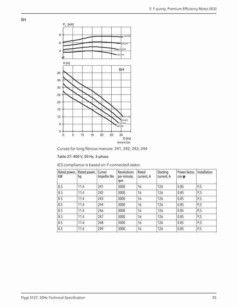
SH
Q [l/s]
H [m]
2P [kW]
0 5 10 15 20 25 300
5
10
15
20
25
30
35
40
4
6
8
SH
241/246
241/246
242/247
242/247
243/248
243/248
244/249
244/249
WS004732A
Curves for long fibrous manure: 241, 242, 243, 244
Table 27: 400 V, 50 Hz, 3–phase
IE3 compliance is based on Y-connected stator.
Rated power,kW
Rated power,hp
Curve/Impeller No
Revolutionsper minute,rpm
Ratedcurrent, A
Startingcurrent, A
Power factor,cos φ
Installation
8.5 11.4 241 3000 16 126 0.85 P,S
8.5 11.4 242 3000 16 126 0.85 P,S
8.5 11.4 243 3000 16 126 0.85 P,S
8.5 11.4 244 3000 16 126 0.85 P,S
8.5 11.4 246 3000 16 126 0.85 P,S
8.5 11.4 247 3000 16 126 0.85 P,S
8.5 11.4 248 3000 16 126 0.85 P,S
8.5 11.4 249 3000 16 126 0.85 P,S
5 F-pump, Premium Efficiency Motor (IE3)
Flygt 3127, 50Hz Technical Specification 35

6 H-pump6.1 Product description
Usage
A submersible pump for water containing abrasive particles, sludge, ground water, orslurries.
Denomination
Type Non-explosion proofversion
Explosion proofversion
Pressure class Installationtypes
Gray iron 3127.182 3127.091 HT — High head S
The pump can be used in the following installations:
S Portable semi permanent, wet well arrangement with hose coupling or flange forconnection to discharge pipeline.
Application limits
Feature Description
Liquid temperature Maximum 40°C (104°F)
Liquid temperature, warm water version Maximum 70°C (158°F)
Depth of immersion Maximum 20 m (65 ft)
pH of the pumped liquid 5.5 – 14
Liquid density Maximum 1100 kg/m3
Motor data
Feature Description
Motor type Squirrel-cage induction motor
Frequency 50 Hz
Power supply 3-phase
Starting method • Direct on-line• Star-delta• Soft starter• Variable Frequency Drive (VFD)
Number of starts per hour Maximum 30
6 H-pump
36 Flygt 3127, 50Hz Technical Specification
Feature Description
Code compliance IEC 60034-1
Voltage variation • Continuously running: Maximum ±5%• Intermittent running: Maximum ±10%
Voltage imbalance betweenphases
Maximum 2%
Stator insulation class H (180°C, 356°F)
Cables
Application Type
Direct-on-line start or Y/D start with two cables Flygt SUBCAB® - a heavy duty 4 cores motor power cablewith two twisted pair screened control cores. Conductorinsulation rating of 90°C, which allows for increasedcurrent. Superior mechanical strength and high abrasionand tear resistant. Chemical resistant within pH 3-10 andozone, oil, and flame resistant. Used up to 70°C watertemperature. Cables < 10 mm2 with unscreened controlcores.
Y/D start Flygt SUBCAB® - a heavy duty 7 cores motor power cablewith two twisted pair screened control cores. Conductorinsulation rating of 90°C, which allows for increasedcurrent. Superior mechanical strength and high abrasionand tear resistant. Chemical resistant within pH 3-10 andozone, oil, and flame resistant. Used up to 70°C watertemperature. Cables < 7G6 mm2 with unscreenedcontrol cores.
Variable Frequency drive Screened Flygt SUBCAB® - a heavy duty 4 screened coresmotor power cable with four twisted pair screenedcontrol cores. Conductor insulation rating of 90°C, whichallows for increased current. Superior mechanicalstrength and high abrasion and tear resistant. Chemicalresistant within pH 3-10 and ozone, oil, and flameresistant. Used up to 70°C water temperature.
Monitoring equipment
• Thermal contacts opening temperature 125° C (257° F)
Materials
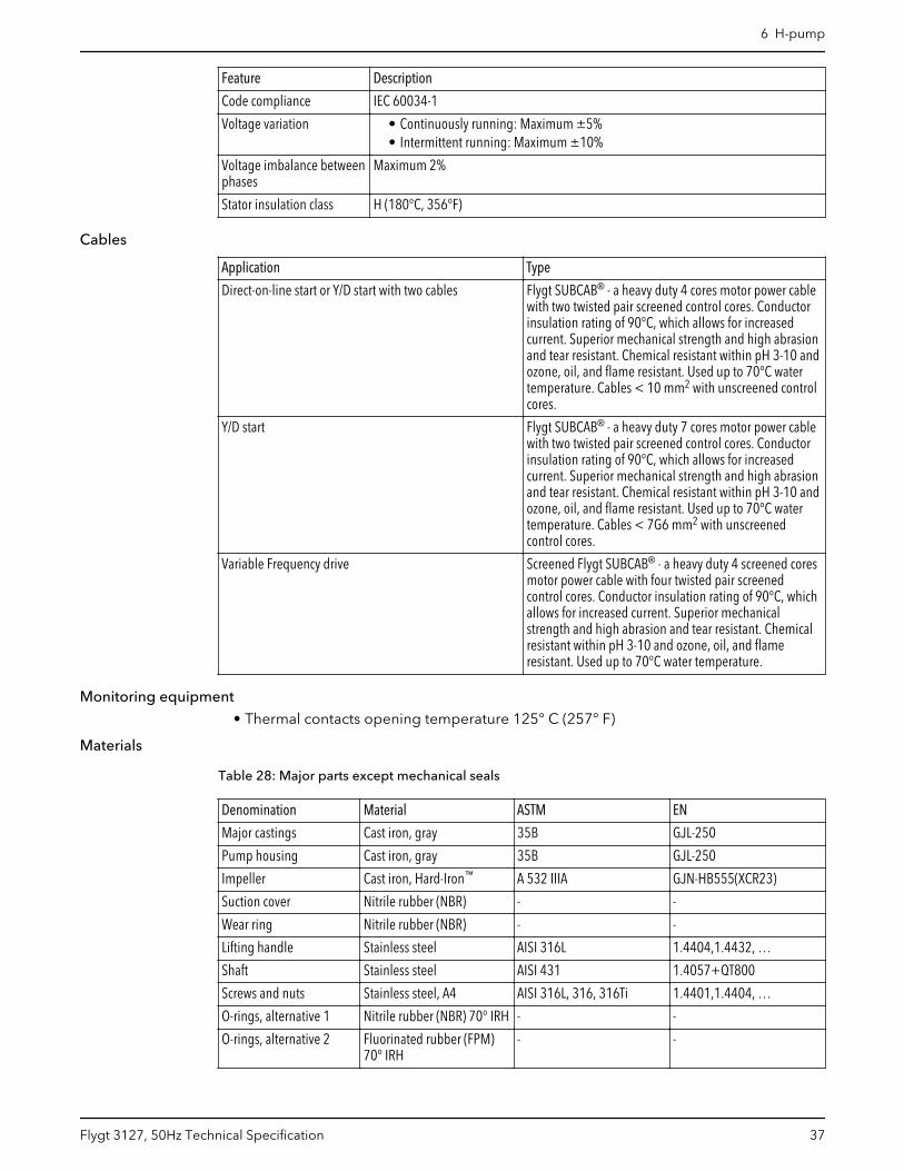
Table 28: Major parts except mechanical seals
Denomination Material ASTM EN
Major castings Cast iron, gray 35B GJL-250
Pump housing Cast iron, gray 35B GJL-250
Impeller Cast iron, Hard-Iron™ A 532 IIIA GJN-HB555(XCR23)
Suction cover Nitrile rubber (NBR) - -
Wear ring Nitrile rubber (NBR) - -
Lifting handle Stainless steel AISI 316L 1.4404,1.4432, …
Shaft Stainless steel AISI 431 1.4057+QT800
Screws and nuts Stainless steel, A4 AISI 316L, 316, 316Ti 1.4401,1.4404, …
O-rings, alternative 1 Nitrile rubber (NBR) 70° IRH - -
O-rings, alternative 2 Fluorinated rubber (FPM)70° IRH
- -
6 H-pump
Flygt 3127, 50Hz Technical Specification 37
Denomination Material ASTM EN
Oil Part No 901752 Medical white oil of paraffintype. Fulfills FDA 172.878(a)
- -
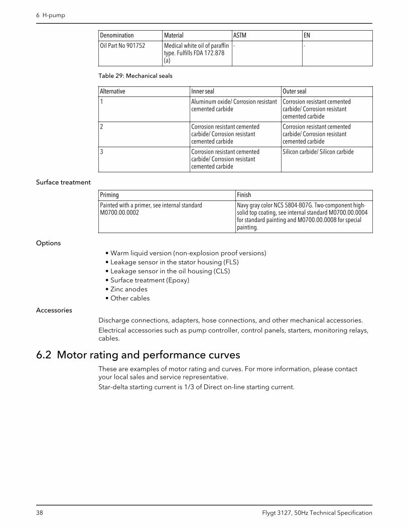
Table 29: Mechanical seals
Alternative Inner seal Outer seal
1 Aluminum oxide/ Corrosion resistantcemented carbide
Corrosion resistant cementedcarbide/ Corrosion resistantcemented carbide
2 Corrosion resistant cementedcarbide/ Corrosion resistantcemented carbide
Corrosion resistant cementedcarbide/ Corrosion resistantcemented carbide
3 Corrosion resistant cementedcarbide/ Corrosion resistantcemented carbide
Silicon carbide/ Silicon carbide
Surface treatment
Priming Finish
Painted with a primer, see internal standardM0700.00.0002
Navy gray color NCS 5804-B07G. Two-component high-solid top coating, see internal standard M0700.00.0004for standard painting and M0700.00.0008 for specialpainting.
Options
• Warm liquid version (non-explosion proof versions)• Leakage sensor in the stator housing (FLS)• Leakage sensor in the oil housing (CLS)• Surface treatment (Epoxy)• Zinc anodes• Other cables
Accessories
Discharge connections, adapters, hose connections, and other mechanical accessories.
Electrical accessories such as pump controller, control panels, starters, monitoring relays,cables.
6.2 Motor rating and performance curvesThese are examples of motor rating and curves. For more information, please contactyour local sales and service representative.
Star-delta starting current is 1/3 of Direct on-line starting current.
6 H-pump
38 Flygt 3127, 50Hz Technical Specification
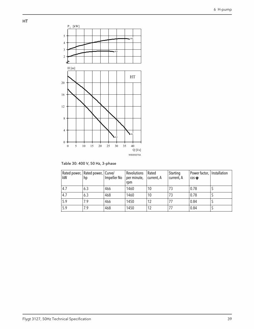
HT
Q [l/s]
H [m]
2P [kW]
0 5 10 15 20 25 30 35 400
4
8
12
16
20
2
3
4
5
HT
466
466
468
468
466
466
468
468
WS005075A
Table 30: 400 V, 50 Hz, 3–phase
Rated power,kW
Rated power,hp
Curve/Impeller No
Revolutionsper minute,rpm
Ratedcurrent, A
Startingcurrent, A
Power factor,cos φ
Installation
4.7 6.3 466 1460 10 73 0.78 S
4.7 6.3 468 1460 10 73 0.78 S
5.9 7.9 466 1450 12 77 0.84 S
5.9 7.9 468 1450 12 77 0.84 S
6 H-pump
Flygt 3127, 50Hz Technical Specification 39
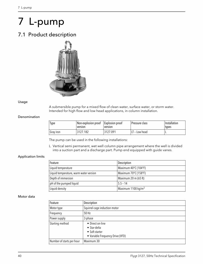
7 L-pump7.1 Product description
Usage
A submersible pump for a mixed flow of clean water, surface water, or storm water.Intended for high flow and low head applications, in column installation.
Denomination
Type Non-explosion proofversion
Explosion proofversion
Pressure class Installationtypes
Gray iron 3127.182 3127.091 LT — Low head L
The pump can be used in the following installations:
L Vertical semi permanent, wet well column pipe arrangement where the well is dividedinto a suction part and a discharge part. Pump end equipped with guide vanes.
Application limits
Feature Description
Liquid temperature Maximum 40°C (104°F)
Liquid temperature, warm water version Maximum 70°C (158°F)
Depth of immersion Maximum 20 m (65 ft)
pH of the pumped liquid 5.5 – 14
Liquid density Maximum 1100 kg/m3
Motor data
Feature Description
Motor type Squirrel-cage induction motor
Frequency 50 Hz
Power supply 3-phase
Starting method • Direct on-line• Star-delta• Soft starter• Variable Frequency Drive (VFD)
Number of starts per hour Maximum 30
7 L-pump
40 Flygt 3127, 50Hz Technical Specification

Feature Description
Code compliance IEC 60034-1
Voltage variation • Continuously running: Maximum ±5%• Intermittent running: Maximum ±10%
Voltage imbalance betweenphases
Maximum 2%
Stator insulation class H (180°C, 356°F)
Cables
Application Type
Direct-on-line start or Y/D start with two cables Flygt SUBCAB® - a heavy duty 4 cores motor power cablewith two twisted pair screened control cores. Conductorinsulation rating of 90°C, which allows for increasedcurrent. Superior mechanical strength and high abrasionand tear resistant. Chemical resistant within pH 3-10 andozone, oil, and flame resistant. Used up to 70°C watertemperature. Cables < 10 mm2 with unscreened controlcores.
Y/D start Flygt SUBCAB® - a heavy duty 7 cores motor power cablewith two twisted pair screened control cores. Conductorinsulation rating of 90°C, which allows for increasedcurrent. Superior mechanical strength and high abrasionand tear resistant. Chemical resistant within pH 3-10 andozone, oil, and flame resistant. Used up to 70°C watertemperature. Cables < 7G6 mm2 with unscreenedcontrol cores.
Variable Frequency drive Screened Flygt SUBCAB® - a heavy duty 4 screened coresmotor power cable with four twisted pair screenedcontrol cores. Conductor insulation rating of 90°C, whichallows for increased current. Superior mechanicalstrength and high abrasion and tear resistant. Chemicalresistant within pH 3-10 and ozone, oil, and flameresistant. Used up to 70°C water temperature.
Monitoring equipment
• Thermal contacts opening temperature 125° C (257° F)
Materials
Table 31: Major parts except mechanical seals
Denomination Material ASTM EN
Major castings Cast iron, gray 35B GJL-250
Pump housing Cast iron, gray 35B GJL-250
Impeller Cast iron, gray 35B GJL-250
Insert ring Cast iron, gray 35B GJL-250
Lifting handle Stainless steel AISI 316L 1.4404,1.4432, …
Shaft Stainless steel AISI 431 1.4057+QT800
Screws and nuts Stainless steel, A4 AISI 316L, 316, 316Ti 1.4401,1.4404, …
O-rings, alternative 1 Nitrile rubber (NBR) 70° IRH - -
O-rings, alternative 2 Fluorinated rubber (FPM)70° IRH
- -
Oil Part No 901752 Medical white oil of paraffintype. Fulfills FDA 172.878(a)
- -
7 L-pump
Flygt 3127, 50Hz Technical Specification 41
Table 32: Mechanical seals
Alternative Inner seal Outer seal
1 Aluminum oxide/ Corrosion resistantcemented carbide
Corrosion resistant cementedcarbide/ Corrosion resistantcemented carbide
2 Corrosion resistant cementedcarbide/ Corrosion resistantcemented carbide
Corrosion resistant cementedcarbide/ Corrosion resistantcemented carbide
3 Corrosion resistant cementedcarbide/ Corrosion resistantcemented carbide
Silicon carbide/ Silicon carbide
Surface treatment
Priming Finish
Painted with a primer, see internal standardM0700.00.0002
Navy gray color NCS 5804-B07G. Two-component high-solid top coating, see internal standard M0700.00.0004for standard painting and M0700.00.0008 for specialpainting.
Options
• Warm liquid version (non-explosion proof versions)• Leakage sensor in the stator housing (FLS)• Leakage sensor in the oil housing (CLS)• Surface treatment (Epoxy)• Zinc anodes• Other cables
Accessories
Discharge connections, adapters, hose connections, and other mechanical accessories.
Electrical accessories such as pump controller, control panels, starters, monitoring relays,cables.
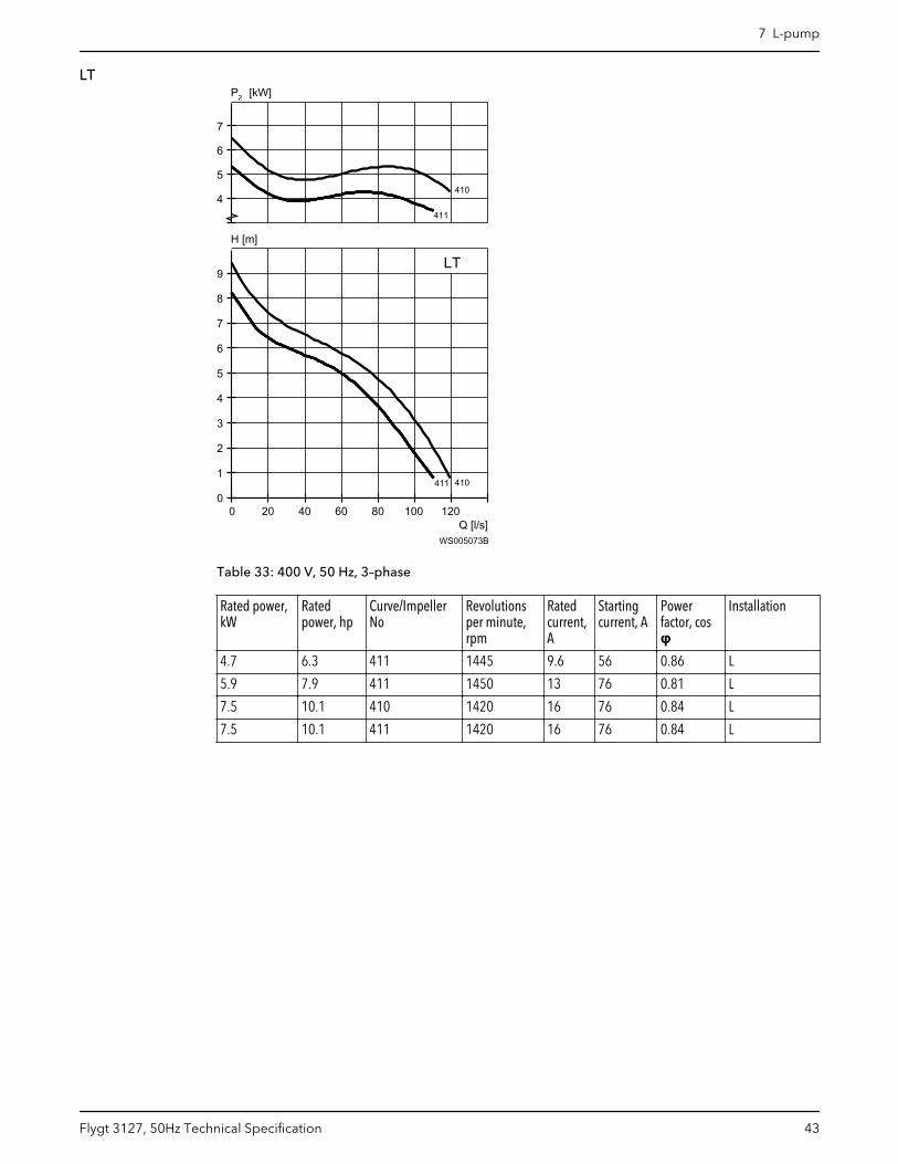
7.2 Motor rating and performance curvesThese are examples of motor rating and curves. For more information, please contactyour local sales and service representative.
Star-delta starting current is 1/3 of Direct on-line starting current.
7 L-pump
42 Flygt 3127, 50Hz Technical Specification
LT
Q [l/s]
H [m]
2P [kW]
0 20 40 60 80 100 1200
1
2
3
4
5
6
7
8
9
4
5
6
7
LT
410
410
411411411411
411
411
WS005073B
Table 33: 400 V, 50 Hz, 3–phase
Rated power,kW
Ratedpower, hp
Curve/ImpellerNo
Revolutionsper minute,rpm
Ratedcurrent,A
Startingcurrent, A
Powerfactor, cosφ
Installation
4.7 6.3 411 1445 9.6 56 0.86 L
5.9 7.9 411 1450 13 76 0.81 L
7.5 10.1 410 1420 16 76 0.84 L
7.5 10.1 411 1420 16 76 0.84 L
7 L-pump
Flygt 3127, 50Hz Technical Specification 43

8 M-pump8.1 Product description
Usage
A submersible pump for wastewater containing solids that need to be macerated. Theimpeller is equipped with a grinder device.
Denomination
Type Non-explosion proofversion
Explosion proofversion
Pressure class Installation types
Gray ironGrinder
3127.170 3127.890 LT — Low headHT — High head
F, P
The pump can be used in the following installations:
F Free standing semi permanent, wet well arrangement where the pump is placed on afirm surface.
P Semi permanent, wet well arrangement with pump installed on two guide bars withautomatic connection to discharge.
Application limits
Feature Description
Liquid temperature Maximum 40°C (104°F)
Depth of immersion Maximum 20 m (65 ft)
pH of the pumped liquid 5.5 – 14
Liquid density Maximum 1100 kg/m3
Motor data
Feature Description
Motor type Squirrel-cage induction motor
Frequency 50 Hz
Power supply 3-phase
Starting method • Direct on-line• Star-delta• Soft starter
Number of starts per hour Maximum 30
8 M-pump
44 Flygt 3127, 50Hz Technical Specification

Feature Description
Code compliance IEC 60034-1
Voltage variation • Continuously running: Maximum ±5%• Intermittent running: Maximum ±10%
Voltage imbalance betweenphases
Maximum 2%
Stator insulation class H (180°C, 356°F)
Cables
Application Type
Direct-on-line start or Y/D start with two cables Flygt SUBCAB® - a heavy duty 4 cores motor power cablewith two twisted pair screened control cores. Conductorinsulation rating of 90°C, which allows for increasedcurrent. Superior mechanical strength and high abrasionand tear resistant. Chemical resistant within pH 3-10 andozone, oil, and flame resistant. Used up to 70°C watertemperature. Cables < 10 mm2 with unscreened controlcores.
Y/D start Flygt SUBCAB® - a heavy duty 7 cores motor power cablewith two twisted pair screened control cores. Conductorinsulation rating of 90°C, which allows for increasedcurrent. Superior mechanical strength and high abrasionand tear resistant. Chemical resistant within pH 3-10 andozone, oil, and flame resistant. Used up to 70°C watertemperature. Cables < 7G6 mm2 with unscreenedcontrol cores.
Monitoring equipment
Thermal contacts opening temperature 125° C (257° F)
Materials
Table 34: Major parts except mechanical seals
Denomination Material ASTM EN
Major castings Cast iron, gray 35B GJL-250
Pump housing Cast iron, gray 35B GJL-250
Impeller, alternative 1 Cast iron, gray 30B GJL-200
Impeller, alternative 2 Cast iron, gray 35B GJL-250
Cutter wheel Cast iron, Hard-Iron™ A 532 IIIA GJN-HB555(XCR23)
Cutter plate Stainless steel - -
Lifting handle Stainless steel AISI 316L 1.4404,1.4432, …
Shaft Stainless steel AISI 431 1.4057+QT800
Screws and nuts Stainless steel, A4 AISI 316L, 316, 316Ti 1.4401,1.4404, …
O-rings Nitrile rubber (NBR) 70° IRH - -
Oil, part no 901752 Medical white oil of paraffintype. Fulfills FDA 172.878(a)
- -
Table 35: Mechanical seals
Inner seal Outer seal
Aluminum oxide/ Corrosion resistant cemented carbide Corrosion resistant cemented carbide/ Corrosion resistantcemented carbide
8 M-pump
Flygt 3127, 50Hz Technical Specification 45
Surface treatment
Priming Finish
Painted with a primer, see internal standardM0700.00.0002
Navy gray color NCS 5804-B07G. Two-component high-solid top coating, see internal standard M0700.00.0004for standard painting and M0700.00.0008 for specialpainting.
Options
• Leakage sensor in the stator housing (FLS)• Leakage sensor in the oil housing (CLS)• Surface treatment (Epoxy)• Zinc anodes• Other cables
Accessories
Discharge connections, adapters, hose connections, and other mechanical accessories.
Electrical accessories such as pump controller, control panels, starters, monitoring relays,cables.
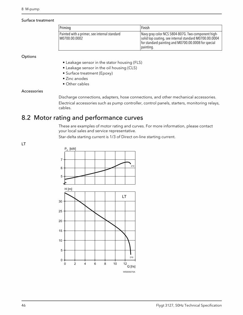
8.2 Motor rating and performance curvesThese are examples of motor rating and curves. For more information, please contactyour local sales and service representative.
Star-delta starting current is 1/3 of Direct on-line starting current.
LT
WS005070A
8 M-pump
46 Flygt 3127, 50Hz Technical Specification
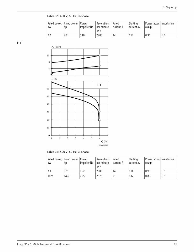
Table 36: 400 V, 50 Hz, 3–phase
Rated power,kW
Rated power,hp
Curve/Impeller No
Revolutionsper minute,rpm
Ratedcurrent, A
Startingcurrent, A
Power factor,cos φ
Installation
7.4 9.9 210 2900 14 114 0.91 F,P
HT
Q [l/s]
H [m]
2P [kW]
0 1 2 3 4 5 60
10
20
30
40
50
60
6
8
10
HT
252
252
255
255
WS005071A
Table 37: 400 V, 50 Hz, 3–phase
Rated power,kW
Rated power,hp
Curve/Impeller No
Revolutionsper minute,rpm
Ratedcurrent, A
Startingcurrent, A
Power factor,cos φ
Installation
7.4 9.9 252 2900 14 114 0.91 F,P
10.9 14.6 255 2875 21 137 0.88 F,P
8 M-pump
Flygt 3127, 50Hz Technical Specification 47

9 N-pump, Standard Motor9.1 Product description
Usage
Installation typeP, S, T, Z
A submersible pump for efficient pumping of clean water, surfacewater, and wastewater containing solids or long-fibered material. Thepump is designed for sustained high efficiency. For abrasive media,Hard-Iron™ is required. Stainless steel N-impeller is available as anoption.
Installation type L A submersible pump for a mixed flow of clean water, surface water, orstorm water. Intended for high flow and low head applications, incolumn installation. The pump is designed for sustained highefficiency.
Denomination
Type Non-explosion proofversion
Explosion proofversion
Pressure class Installation types
AdaptiveGray iron
3127.160 3127.190 LT — Low headMT — Medium headHT — High headSH — Super head
L, P, S, T, Z
Hard-Iron™ 3127.185 3127.095 LT — Low headMT — Medium headHT — High headSH — Super head
P, S, T, Z
AdaptiveStainless steel
3127.760 3127.770 LT — Low headMT — Medium headHT — High head
P, S
The pump can be used in the following installations:
L Vertical semi permanent, wet well column pipe arrangement where the well is dividedinto a suction part and a discharge part. Pump end equipped with guide vanes.
P Semi permanent, wet well arrangement with pump installed on two guide bars withautomatic connection to discharge.
9 N-pump, Standard Motor
48 Flygt 3127, 50Hz Technical Specification
S Portable semi permanent, wet well arrangement with hose coupling or flange forconnection to discharge pipeline.
T Vertical permanent, dry well arrangement with flange connection to suction anddischarge piping.
Z Horizontal permanent, dry well arrangement with flange connection to suction anddischarge piping.
Application limits
Feature Description
Liquid temperature Maximum 40°C (104°F)
Liquid temperature, warm water version Maximum 70°C (158°F)
Depth of immersion Maximum 20 m (65 ft)
pH of the pumped liquid 5.5 – 14
Liquid density Maximum 1100 kg/m3
Motor data
Feature Description
Motor type Squirrel-cage induction motor
Frequency 50 Hz
Power supply 3-phase
Starting method • Direct on-line• Star-delta• Soft starter• Variable Frequency Drive (VFD)
Number of starts per hour Maximum 30
Code compliance IEC 60034-1
Voltage variation • Continuously running: Maximum ±5%• Intermittent running: Maximum ±10%
Voltage imbalance betweenphases
Maximum 2%
Stator insulation class H (180°C, 356°F)
Cables
Application Type
Direct-on-line start or Y/D start with two cables Flygt SUBCAB® - a heavy duty 4 cores motor power cablewith two twisted pair screened control cores. Conductorinsulation rating of 90°C, which allows for increasedcurrent. Superior mechanical strength and high abrasionand tear resistant. Chemical resistant within pH 3-10 andozone, oil, and flame resistant. Used up to 70°C watertemperature. Cables < 10 mm2 with unscreened controlcores.
Y/D start Flygt SUBCAB® - a heavy duty 7 cores motor power cablewith two twisted pair screened control cores. Conductorinsulation rating of 90°C, which allows for increasedcurrent. Superior mechanical strength and high abrasionand tear resistant. Chemical resistant within pH 3-10 andozone, oil, and flame resistant. Used up to 70°C watertemperature. Cables < 7G6 mm2 with unscreenedcontrol cores.
9 N-pump, Standard Motor
Flygt 3127, 50Hz Technical Specification 49
Application Type
Variable Frequency drive Screened Flygt SUBCAB® - a heavy duty 4 screened coresmotor power cable with four twisted pair screenedcontrol cores. Conductor insulation rating of 90°C, whichallows for increased current. Superior mechanicalstrength and high abrasion and tear resistant. Chemicalresistant within pH 3-10 and ozone, oil, and flameresistant. Used up to 70°C water temperature.
Monitoring equipment
Thermal contacts opening temperature 125° C (257° F)
Materials
Table 38: Major parts except mechanical seals
Denomination Material ASTM EN
Major castings Cast iron, gray 35B GJL-250
Pump housing Cast iron, gray 35B GJL-250
Impeller, alternative 1 Cast iron, gray 35B GJL-250
Impeller, alternative 2 Cast iron, Hard-Iron™ A 532 IIIA GJN-HB555(XCR23)
Impeller, alternative 3 Stainless steel, Duplex CD-4MCuN 10283:2010 -1.4474
Insert ring, alternative 1 Cast iron, gray 35B GJL-250
Insert ring, alternative 2 Cast iron, Hard-Iron™ A 532 IIIA GJN-HB555(XCR23)
Lifting handle Stainless steel AISI 316L 1.4404,1.4432, …
Shaft Stainless steel AISI 431 1.4057+QT800
Screws and nuts Stainless steel, A4 AISI 316L, 316, 316Ti 1.4401,1.4404, …
O-rings, alternative 1 Nitrile rubber (NBR) 70° IRH - -
O-rings, alternative 2 Fluorinated rubber (FPM)70° IRH
- -
Oil, part no 901752 Medical white oil of paraffintype. Fulfills FDA 172.878(a)
- -
Table 39: Mechanical seals
Alternative Inner seal Outer seal
1 Aluminum oxide/ Corrosion resistantcemented carbide
Corrosion resistant cementedcarbide/ Corrosion resistantcemented carbide
2 Corrosion resistant cementedcarbide/ Corrosion resistantcemented carbide
Corrosion resistant cementedcarbide/ Corrosion resistantcemented carbide
3 Corrosion resistant cementedcarbide/ Corrosion resistantcemented carbide
Silicon carbide/ Silicon carbide
Surface treatment
Priming Finish
Painted with a primer, see internal standardM0700.00.0002
Navy gray color NCS 5804-B07G. Two-component high-solid top coating, see internal standard M0700.00.0004for standard painting and M0700.00.0008 for specialpainting.
9 N-pump, Standard Motor
50 Flygt 3127, 50Hz Technical Specification
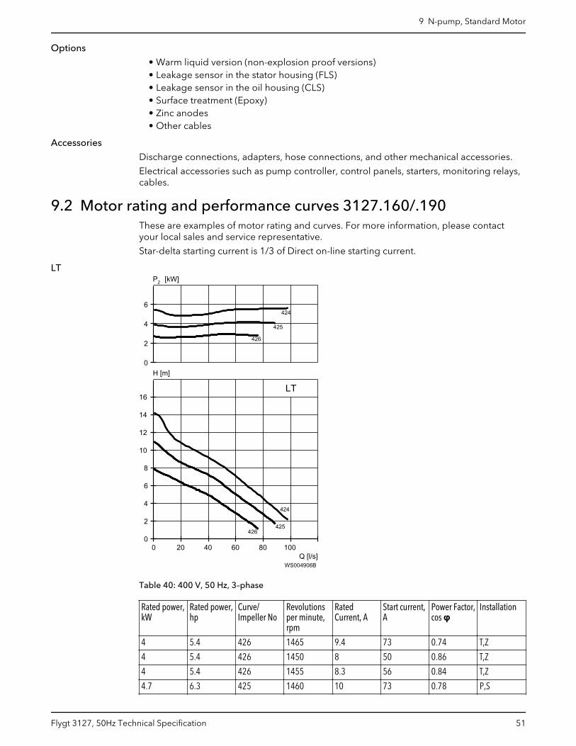
Options
• Warm liquid version (non-explosion proof versions)• Leakage sensor in the stator housing (FLS)• Leakage sensor in the oil housing (CLS)• Surface treatment (Epoxy)• Zinc anodes• Other cables
Accessories
Discharge connections, adapters, hose connections, and other mechanical accessories.
Electrical accessories such as pump controller, control panels, starters, monitoring relays,cables.
9.2 Motor rating and performance curves 3127.160/.190These are examples of motor rating and curves. For more information, please contactyour local sales and service representative.
Star-delta starting current is 1/3 of Direct on-line starting current.
LT
Q [l/s]
H [m]
2P [kW]
0 20 40 60 80 1000
2
4
6
8
10
12
14
16
0
2
4
6
LT
424
424
425425425425425425425425425
425
426
426
WS004906B
Table 40: 400 V, 50 Hz, 3–phase
Rated power,kW
Rated power,hp
Curve/Impeller No
Revolutionsper minute,rpm
RatedCurrent, A
Start current,A
Power Factor,cos φ
Installation
4 5.4 426 1465 9.4 73 0.74 T,Z
4 5.4 426 1450 8 50 0.86 T,Z
4 5.4 426 1455 8.3 56 0.84 T,Z
4.7 6.3 425 1460 10 73 0.78 P,S
9 N-pump, Standard Motor
Flygt 3127, 50Hz Technical Specification 51
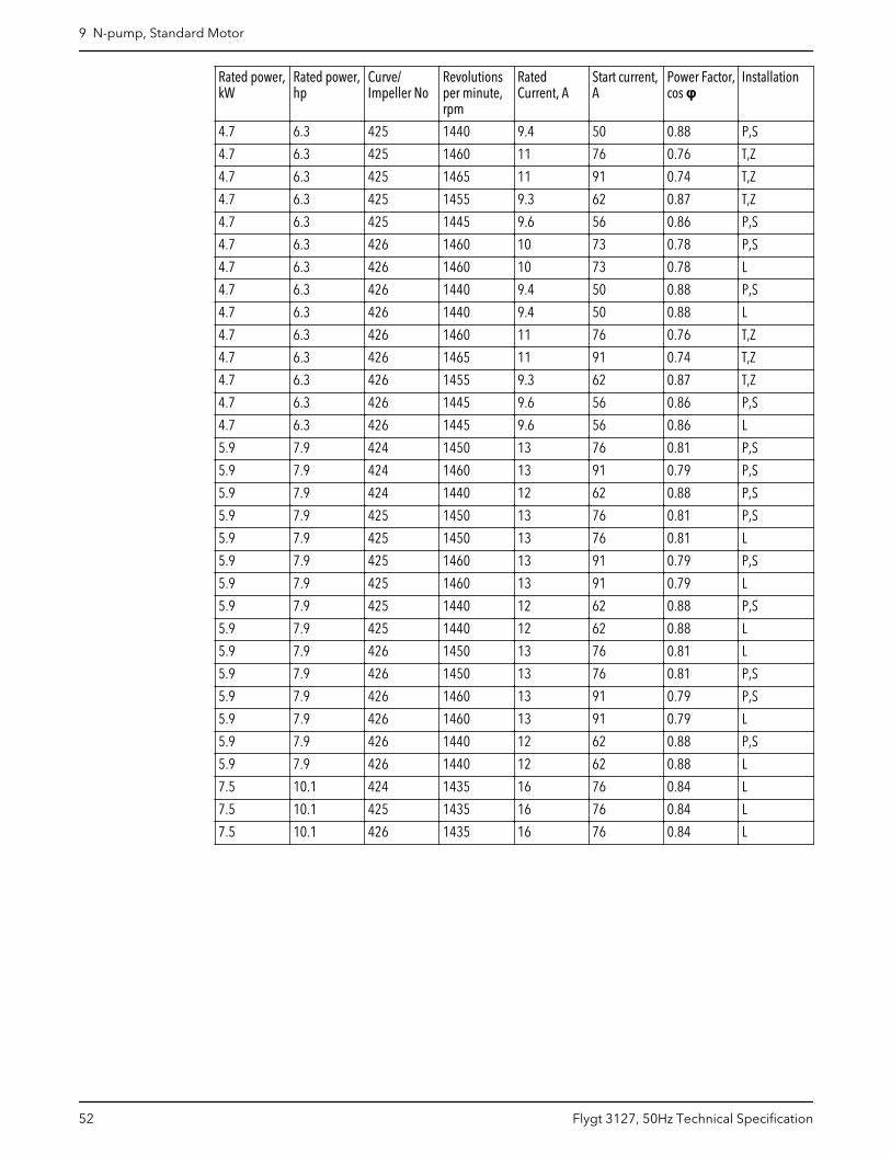
Rated power,kW
Rated power,hp
Curve/Impeller No
Revolutionsper minute,rpm
RatedCurrent, A
Start current,A
Power Factor,cos φ
Installation
4.7 6.3 425 1440 9.4 50 0.88 P,S
4.7 6.3 425 1460 11 76 0.76 T,Z
4.7 6.3 425 1465 11 91 0.74 T,Z
4.7 6.3 425 1455 9.3 62 0.87 T,Z
4.7 6.3 425 1445 9.6 56 0.86 P,S
4.7 6.3 426 1460 10 73 0.78 P,S
4.7 6.3 426 1460 10 73 0.78 L
4.7 6.3 426 1440 9.4 50 0.88 P,S
4.7 6.3 426 1440 9.4 50 0.88 L
4.7 6.3 426 1460 11 76 0.76 T,Z
4.7 6.3 426 1465 11 91 0.74 T,Z
4.7 6.3 426 1455 9.3 62 0.87 T,Z
4.7 6.3 426 1445 9.6 56 0.86 P,S
4.7 6.3 426 1445 9.6 56 0.86 L
5.9 7.9 424 1450 13 76 0.81 P,S
5.9 7.9 424 1460 13 91 0.79 P,S
5.9 7.9 424 1440 12 62 0.88 P,S
5.9 7.9 425 1450 13 76 0.81 P,S
5.9 7.9 425 1450 13 76 0.81 L
5.9 7.9 425 1460 13 91 0.79 P,S
5.9 7.9 425 1460 13 91 0.79 L
5.9 7.9 425 1440 12 62 0.88 P,S
5.9 7.9 425 1440 12 62 0.88 L
5.9 7.9 426 1450 13 76 0.81 L
5.9 7.9 426 1450 13 76 0.81 P,S
5.9 7.9 426 1460 13 91 0.79 P,S
5.9 7.9 426 1460 13 91 0.79 L
5.9 7.9 426 1440 12 62 0.88 P,S
5.9 7.9 426 1440 12 62 0.88 L
7.5 10.1 424 1435 16 76 0.84 L
7.5 10.1 425 1435 16 76 0.84 L
7.5 10.1 426 1435 16 76 0.84 L
9 N-pump, Standard Motor
52 Flygt 3127, 50Hz Technical Specification
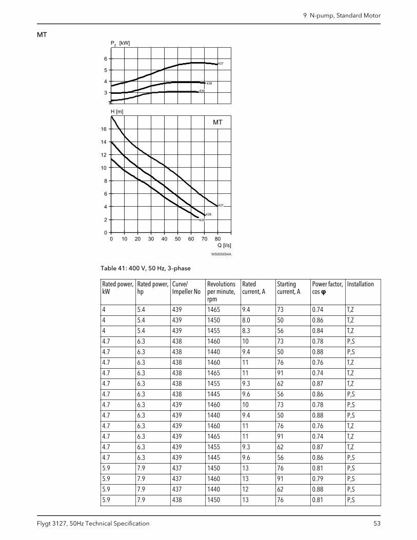
MT
Q [l/s]
H [m]
2P [kW]
0 10 20 30 40 50 60 70 800
2
4
6
8
10
12
14
16
3
4
5
6
437
437
437
437
438438
438
439
439
439
MT
WS005054A
Table 41: 400 V, 50 Hz, 3–phase
Rated power,kW
Rated power,hp
Curve/Impeller No
Revolutionsper minute,rpm
Ratedcurrent, A
Startingcurrent, A
Power factor,cos φ
Installation
4 5.4 439 1465 9.4 73 0.74 T,Z
4 5.4 439 1450 8.0 50 0.86 T,Z
4 5.4 439 1455 8.3 56 0.84 T,Z
4.7 6.3 438 1460 10 73 0.78 P,S
4.7 6.3 438 1440 9.4 50 0.88 P,S
4.7 6.3 438 1460 11 76 0.76 T,Z
4.7 6.3 438 1465 11 91 0.74 T,Z
4.7 6.3 438 1455 9.3 62 0.87 T,Z
4.7 6.3 438 1445 9.6 56 0.86 P,S
4.7 6.3 439 1460 10 73 0.78 P,S
4.7 6.3 439 1440 9.4 50 0.88 P,S
4.7 6.3 439 1460 11 76 0.76 T,Z
4.7 6.3 439 1465 11 91 0.74 T,Z
4.7 6.3 439 1455 9.3 62 0.87 T,Z
4.7 6.3 439 1445 9.6 56 0.86 P,S
5.9 7.9 437 1450 13 76 0.81 P,S
5.9 7.9 437 1460 13 91 0.79 P,S
5.9 7.9 437 1440 12 62 0.88 P,S
5.9 7.9 438 1450 13 76 0.81 P,S
9 N-pump, Standard Motor
Flygt 3127, 50Hz Technical Specification 53
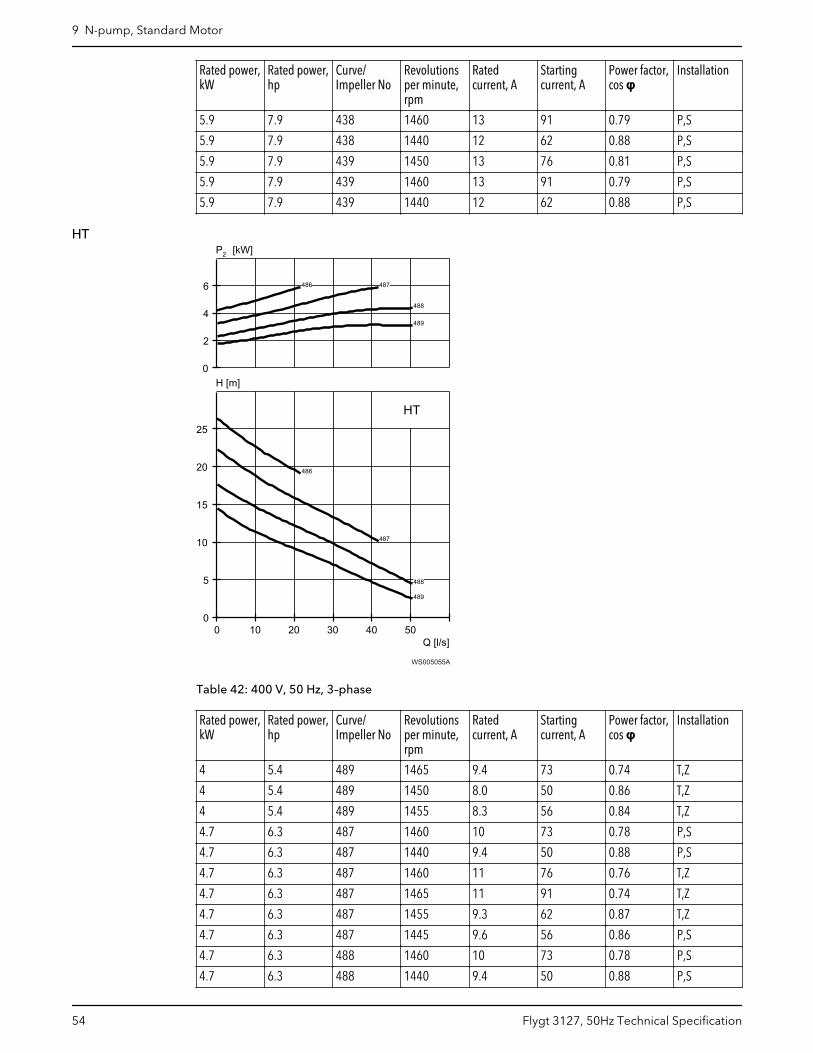
Rated power,kW
Rated power,hp
Curve/Impeller No
Revolutionsper minute,rpm
Ratedcurrent, A
Startingcurrent, A
Power factor,cos φ
Installation
5.9 7.9 438 1460 13 91 0.79 P,S
5.9 7.9 438 1440 12 62 0.88 P,S
5.9 7.9 439 1450 13 76 0.81 P,S
5.9 7.9 439 1460 13 91 0.79 P,S
5.9 7.9 439 1440 12 62 0.88 P,S
HT
Q [l/s]
H [m]
2P [kW]
0 10 20 30 40 500
5
10
15
20
25
0
2
4
6
486
486
487
487
488
488
489
489
HT
WS005055A
Table 42: 400 V, 50 Hz, 3–phase
Rated power,kW
Rated power,hp
Curve/Impeller No
Revolutionsper minute,rpm
Ratedcurrent, A
Startingcurrent, A
Power factor,cos φ
Installation
4 5.4 489 1465 9.4 73 0.74 T,Z
4 5.4 489 1450 8.0 50 0.86 T,Z
4 5.4 489 1455 8.3 56 0.84 T,Z
4.7 6.3 487 1460 10 73 0.78 P,S
4.7 6.3 487 1440 9.4 50 0.88 P,S
4.7 6.3 487 1460 11 76 0.76 T,Z
4.7 6.3 487 1465 11 91 0.74 T,Z
4.7 6.3 487 1455 9.3 62 0.87 T,Z
4.7 6.3 487 1445 9.6 56 0.86 P,S
4.7 6.3 488 1460 10 73 0.78 P,S
4.7 6.3 488 1440 9.4 50 0.88 P,S
9 N-pump, Standard Motor
54 Flygt 3127, 50Hz Technical Specification
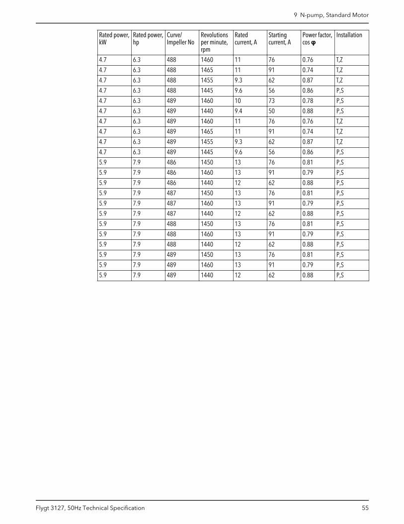
Rated power,kW
Rated power,hp
Curve/Impeller No
Revolutionsper minute,rpm
Ratedcurrent, A
Startingcurrent, A
Power factor,cos φ
Installation
4.7 6.3 488 1460 11 76 0.76 T,Z
4.7 6.3 488 1465 11 91 0.74 T,Z
4.7 6.3 488 1455 9.3 62 0.87 T,Z
4.7 6.3 488 1445 9.6 56 0.86 P,S
4.7 6.3 489 1460 10 73 0.78 P,S
4.7 6.3 489 1440 9.4 50 0.88 P,S
4.7 6.3 489 1460 11 76 0.76 T,Z
4.7 6.3 489 1465 11 91 0.74 T,Z
4.7 6.3 489 1455 9.3 62 0.87 T,Z
4.7 6.3 489 1445 9.6 56 0.86 P,S
5.9 7.9 486 1450 13 76 0.81 P,S
5.9 7.9 486 1460 13 91 0.79 P,S
5.9 7.9 486 1440 12 62 0.88 P,S
5.9 7.9 487 1450 13 76 0.81 P,S
5.9 7.9 487 1460 13 91 0.79 P,S
5.9 7.9 487 1440 12 62 0.88 P,S
5.9 7.9 488 1450 13 76 0.81 P,S
5.9 7.9 488 1460 13 91 0.79 P,S
5.9 7.9 488 1440 12 62 0.88 P,S
5.9 7.9 489 1450 13 76 0.81 P,S
5.9 7.9 489 1460 13 91 0.79 P,S
5.9 7.9 489 1440 12 62 0.88 P,S
9 N-pump, Standard Motor
Flygt 3127, 50Hz Technical Specification 55
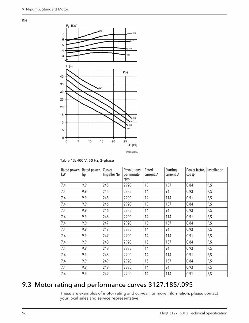
SH
Q [l/s]
H [m]
2P [kW]
0 5 10 15 20 250
5
10
15
20
25
30
35
40
4
5
6
7
3
SH
245
246
247
247
248
249
248
249
246245
WS005056A
Table 43: 400 V, 50 Hz, 3–phase
Rated power,kW
Rated power,hp
Curve/Impeller No
Revolutionsper minute,rpm
Ratedcurrent, A
Startingcurrent, A
Power factor,cos φ
Installation
7.4 9.9 245 2920 15 137 0.84 P,S
7.4 9.9 245 2885 14 94 0.93 P,S
7.4 9.9 245 2900 14 114 0.91 P,S
7.4 9.9 246 2920 15 137 0.84 P,S
7.4 9.9 246 2885 14 94 0.93 P,S
7.4 9.9 246 2900 14 114 0.91 P,S
7.4 9.9 247 2920 15 137 0.84 P,S
7.4 9.9 247 2885 14 94 0.93 P,S
7.4 9.9 247 2900 14 114 0.91 P,S
7.4 9.9 248 2920 15 137 0.84 P,S
7.4 9.9 248 2885 14 94 0.93 P,S
7.4 9.9 248 2900 14 114 0.91 P,S
7.4 9.9 249 2920 15 137 0.84 P,S
7.4 9.9 249 2885 14 94 0.93 P,S
7.4 9.9 249 2900 14 114 0.91 P,S
9.3 Motor rating and performance curves 3127.185/.095These are examples of motor rating and curves. For more information, please contactyour local sales and service representative.
9 N-pump, Standard Motor
56 Flygt 3127, 50Hz Technical Specification
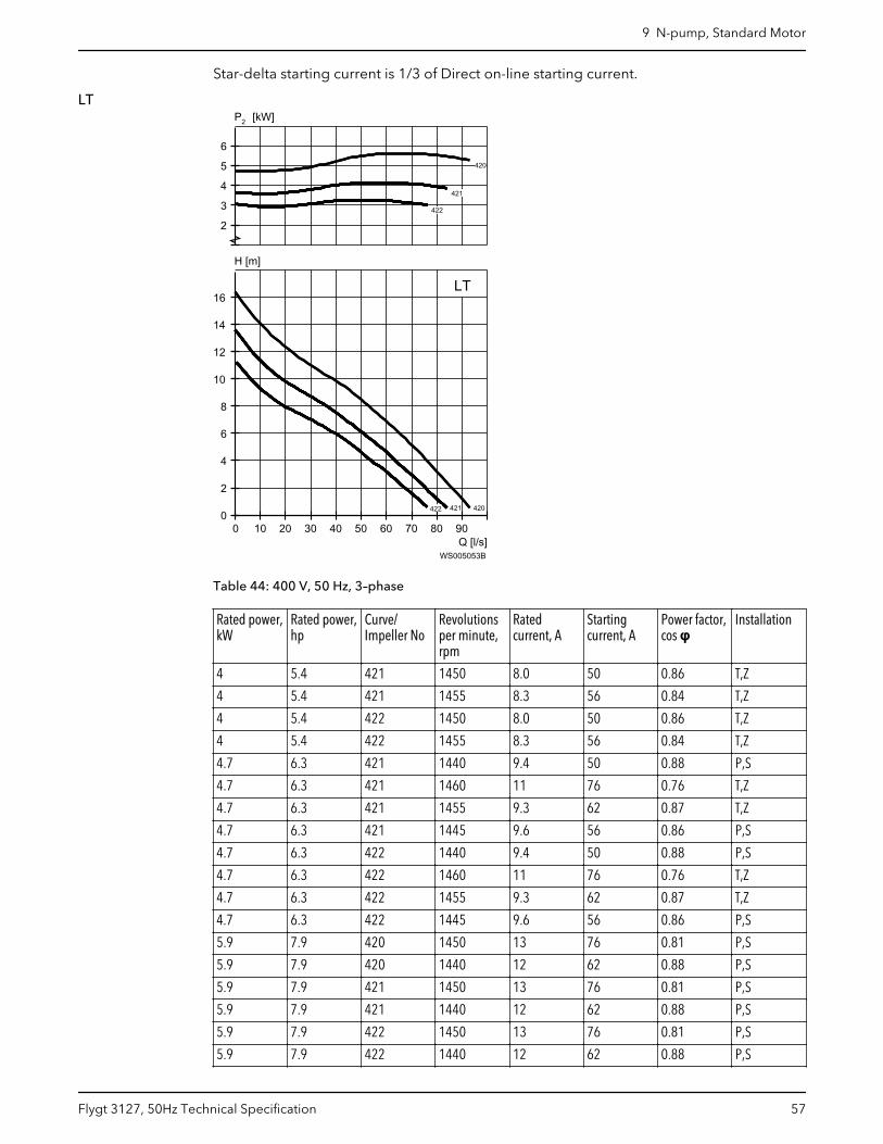
Star-delta starting current is 1/3 of Direct on-line starting current.
LT
Q [l/s]
H [m]
2P [kW]
0 10 20 30 40 50 60 70 80 900
2
4
6
8
10
12
14
16
2
3
4
5
6
LT
420
420
420
420
420
420
421
421
421
421
421
421
421
421
421
421
421
421
421
421
421
421
421
421
421
421
421
421
421
421
422
422
422
422
422
422
422
422
422
422
422
422
422
422
422
422
422
422
422
422
422
422
422
422
WS005053B
Table 44: 400 V, 50 Hz, 3–phase
Rated power,kW
Rated power,hp
Curve/Impeller No
Revolutionsper minute,rpm
Ratedcurrent, A
Startingcurrent, A
Power factor,cos φ
Installation
4 5.4 421 1450 8.0 50 0.86 T,Z
4 5.4 421 1455 8.3 56 0.84 T,Z
4 5.4 422 1450 8.0 50 0.86 T,Z
4 5.4 422 1455 8.3 56 0.84 T,Z
4.7 6.3 421 1440 9.4 50 0.88 P,S
4.7 6.3 421 1460 11 76 0.76 T,Z
4.7 6.3 421 1455 9.3 62 0.87 T,Z
4.7 6.3 421 1445 9.6 56 0.86 P,S
4.7 6.3 422 1440 9.4 50 0.88 P,S
4.7 6.3 422 1460 11 76 0.76 T,Z
4.7 6.3 422 1455 9.3 62 0.87 T,Z
4.7 6.3 422 1445 9.6 56 0.86 P,S
5.9 7.9 420 1450 13 76 0.81 P,S
5.9 7.9 420 1440 12 62 0.88 P,S
5.9 7.9 421 1450 13 76 0.81 P,S
5.9 7.9 421 1440 12 62 0.88 P,S
5.9 7.9 422 1450 13 76 0.81 P,S
5.9 7.9 422 1440 12 62 0.88 P,S
9 N-pump, Standard Motor
Flygt 3127, 50Hz Technical Specification 57
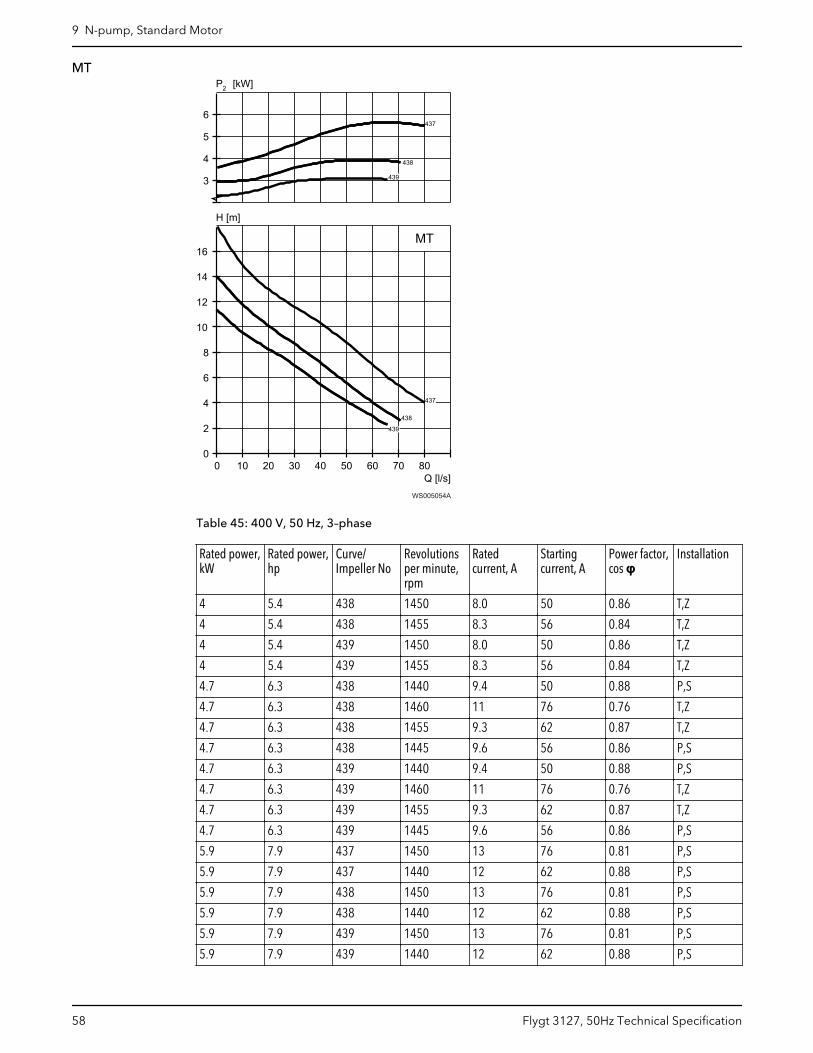
MT
Q [l/s]
H [m]
2P [kW]
0 10 20 30 40 50 60 70 800
2
4
6
8
10
12
14
16
3
4
5
6
437
437
437
437
438438
438
439
439
439
MT
WS005054A
Table 45: 400 V, 50 Hz, 3–phase
Rated power,kW
Rated power,hp
Curve/Impeller No
Revolutionsper minute,rpm
Ratedcurrent, A
Startingcurrent, A
Power factor,cos φ
Installation
4 5.4 438 1450 8.0 50 0.86 T,Z
4 5.4 438 1455 8.3 56 0.84 T,Z
4 5.4 439 1450 8.0 50 0.86 T,Z
4 5.4 439 1455 8.3 56 0.84 T,Z
4.7 6.3 438 1440 9.4 50 0.88 P,S
4.7 6.3 438 1460 11 76 0.76 T,Z
4.7 6.3 438 1455 9.3 62 0.87 T,Z
4.7 6.3 438 1445 9.6 56 0.86 P,S
4.7 6.3 439 1440 9.4 50 0.88 P,S
4.7 6.3 439 1460 11 76 0.76 T,Z
4.7 6.3 439 1455 9.3 62 0.87 T,Z
4.7 6.3 439 1445 9.6 56 0.86 P,S
5.9 7.9 437 1450 13 76 0.81 P,S
5.9 7.9 437 1440 12 62 0.88 P,S
5.9 7.9 438 1450 13 76 0.81 P,S
5.9 7.9 438 1440 12 62 0.88 P,S
5.9 7.9 439 1450 13 76 0.81 P,S
5.9 7.9 439 1440 12 62 0.88 P,S
9 N-pump, Standard Motor
58 Flygt 3127, 50Hz Technical Specification
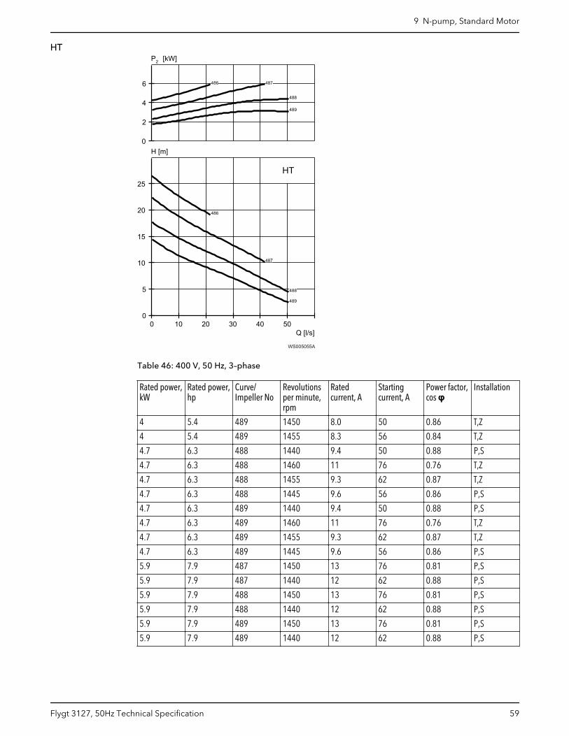
HT
Q [l/s]
H [m]
2P [kW]
0 10 20 30 40 500
5
10
15
20
25
0
2
4
6
486
486
487
487
488
488
489
489
HT
WS005055A
Table 46: 400 V, 50 Hz, 3–phase
Rated power,kW
Rated power,hp
Curve/Impeller No
Revolutionsper minute,rpm
Ratedcurrent, A
Startingcurrent, A
Power factor,cos φ
Installation
4 5.4 489 1450 8.0 50 0.86 T,Z
4 5.4 489 1455 8.3 56 0.84 T,Z
4.7 6.3 488 1440 9.4 50 0.88 P,S
4.7 6.3 488 1460 11 76 0.76 T,Z
4.7 6.3 488 1455 9.3 62 0.87 T,Z
4.7 6.3 488 1445 9.6 56 0.86 P,S
4.7 6.3 489 1440 9.4 50 0.88 P,S
4.7 6.3 489 1460 11 76 0.76 T,Z
4.7 6.3 489 1455 9.3 62 0.87 T,Z
4.7 6.3 489 1445 9.6 56 0.86 P,S
5.9 7.9 487 1450 13 76 0.81 P,S
5.9 7.9 487 1440 12 62 0.88 P,S
5.9 7.9 488 1450 13 76 0.81 P,S
5.9 7.9 488 1440 12 62 0.88 P,S
5.9 7.9 489 1450 13 76 0.81 P,S
5.9 7.9 489 1440 12 62 0.88 P,S
9 N-pump, Standard Motor
Flygt 3127, 50Hz Technical Specification 59
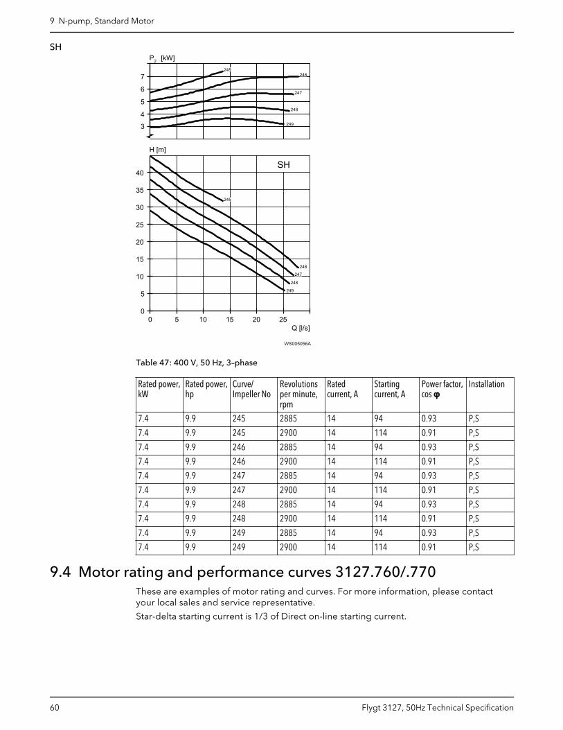
SH
Q [l/s]
H [m]
2P [kW]
0 5 10 15 20 250
5
10
15
20
25
30
35
40
4
5
6
7
3
SH
245
246
247
247
248
249
248
249
246245
WS005056A
Table 47: 400 V, 50 Hz, 3–phase
Rated power,kW
Rated power,hp
Curve/Impeller No
Revolutionsper minute,rpm
Ratedcurrent, A
Startingcurrent, A
Power factor,cos φ
Installation
7.4 9.9 245 2885 14 94 0.93 P,S
7.4 9.9 245 2900 14 114 0.91 P,S
7.4 9.9 246 2885 14 94 0.93 P,S
7.4 9.9 246 2900 14 114 0.91 P,S
7.4 9.9 247 2885 14 94 0.93 P,S
7.4 9.9 247 2900 14 114 0.91 P,S
7.4 9.9 248 2885 14 94 0.93 P,S
7.4 9.9 248 2900 14 114 0.91 P,S
7.4 9.9 249 2885 14 94 0.93 P,S
7.4 9.9 249 2900 14 114 0.91 P,S
9.4 Motor rating and performance curves 3127.760/.770These are examples of motor rating and curves. For more information, please contactyour local sales and service representative.
Star-delta starting current is 1/3 of Direct on-line starting current.
9 N-pump, Standard Motor
60 Flygt 3127, 50Hz Technical Specification
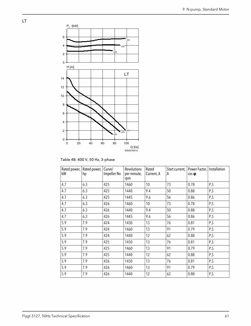
LT
Q [l/s]
H [m]
2P [kW]
0 20 40 60 80 1000
2
4
6
8
10
12
14
0
2
4
6
LT
424
424
424
424
424
424
424
424
424
424
424
424
425
425
425
425
425
425
425
425
425
425
425
425
425
425
425
425
425
425
425
425
425
425
425
425
425
425
425
425
425
425
425
425
425
425
425
425
426
426
426
426
426
426
426
426
426
426
426
426
426
426
426
426
426
426
426
426
426
426
426
426
426
426
426
426
426
426
426
426
426
426
426
426
426
426
426
426
426
426
426
426
426
426
426
426
WS007641A
Table 48: 400 V, 50 Hz, 3–phase
Rated power,kW
Rated power,hp
Curve/Impeller No
Revolutionsper minute,rpm
RatedCurrent, A
Start current,A
Power Factor,cos φ
Installation
4.7 6.3 425 1460 10 73 0.78 P,S
4.7 6.3 425 1440 9.4 50 0.88 P,S
4.7 6.3 425 1445 9.6 56 0.86 P,S
4.7 6.3 426 1460 10 73 0.78 P,S
4.7 6.3 426 1440 9.4 50 0.88 P,S
4.7 6.3 426 1445 9.6 56 0.86 P,S
5.9 7.9 424 1450 13 76 0.81 P,S
5.9 7.9 424 1460 13 91 0.79 P,S
5.9 7.9 424 1440 12 62 0.88 P,S
5.9 7.9 425 1450 13 76 0.81 P,S
5.9 7.9 425 1460 13 91 0.79 P,S
5.9 7.9 425 1440 12 62 0.88 P,S
5.9 7.9 426 1450 13 76 0.81 P,S
5.9 7.9 426 1460 13 91 0.79 P,S
5.9 7.9 426 1440 12 62 0.88 P,S
9 N-pump, Standard Motor
Flygt 3127, 50Hz Technical Specification 61
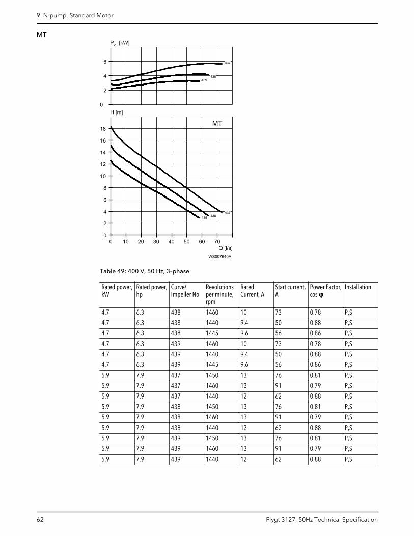
MT
Q [l/s]
H [m]
2P [kW]
0 10 20 30 40 50 60 700
2
4
6
8
10
12
14
16
18
0
2
4
6
MT
437
437
437
437
437
437
438
438
438
438
438
438
438
438
438
438
438
438
438
438
438
438
438
438
439
439
439
439
439
439
439
439
439
439
439
439
439
439
439
439
439
439
439
439
439
439
439
439
WS007640A
Table 49: 400 V, 50 Hz, 3–phase
Rated power,kW
Rated power,hp
Curve/Impeller No
Revolutionsper minute,rpm
RatedCurrent, A
Start current,A
Power Factor,cos φ
Installation
4.7 6.3 438 1460 10 73 0.78 P,S
4.7 6.3 438 1440 9.4 50 0.88 P,S
4.7 6.3 438 1445 9.6 56 0.86 P,S
4.7 6.3 439 1460 10 73 0.78 P,S
4.7 6.3 439 1440 9.4 50 0.88 P,S
4.7 6.3 439 1445 9.6 56 0.86 P,S
5.9 7.9 437 1450 13 76 0.81 P,S
5.9 7.9 437 1460 13 91 0.79 P,S
5.9 7.9 437 1440 12 62 0.88 P,S
5.9 7.9 438 1450 13 76 0.81 P,S
5.9 7.9 438 1460 13 91 0.79 P,S
5.9 7.9 438 1440 12 62 0.88 P,S
5.9 7.9 439 1450 13 76 0.81 P,S
5.9 7.9 439 1460 13 91 0.79 P,S
5.9 7.9 439 1440 12 62 0.88 P,S
9 N-pump, Standard Motor
62 Flygt 3127, 50Hz Technical Specification
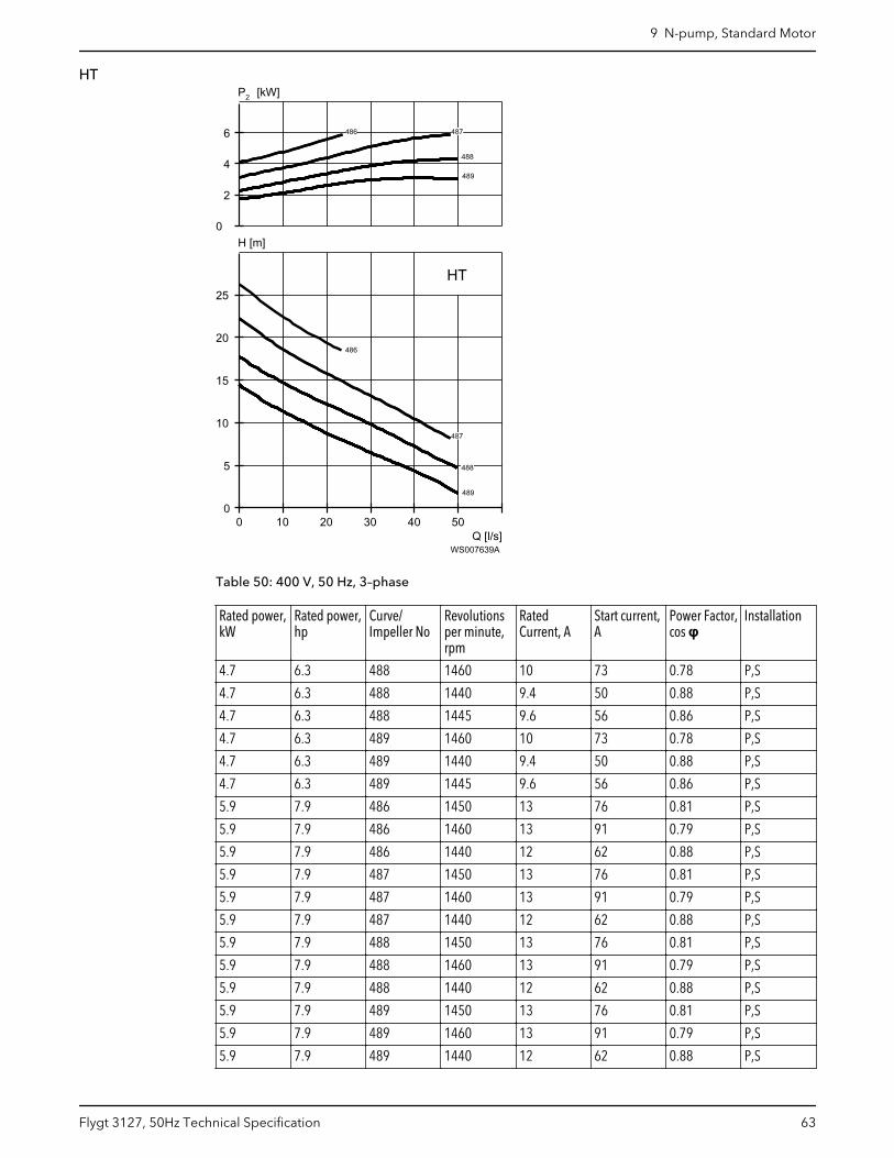
HT
Q [l/s]
H [m]
2P [kW]
0 10 20 30 40 500
5
10
15
20
25
0
2
4
6
HT
486
486
486
486
486
486
487
487
487
487
487
487
488
488
488
488
488
488
488
488
488
488
488
488
488
488
488
488
488
488
489
489
489
489
489
489
489
489
489
489
489
489
489
489
489
489
489
489
489
489
489
489
489
489
WS007639A
Table 50: 400 V, 50 Hz, 3–phase
Rated power,kW
Rated power,hp
Curve/Impeller No
Revolutionsper minute,rpm
RatedCurrent, A
Start current,A
Power Factor,cos φ
Installation
4.7 6.3 488 1460 10 73 0.78 P,S
4.7 6.3 488 1440 9.4 50 0.88 P,S
4.7 6.3 488 1445 9.6 56 0.86 P,S
4.7 6.3 489 1460 10 73 0.78 P,S
4.7 6.3 489 1440 9.4 50 0.88 P,S
4.7 6.3 489 1445 9.6 56 0.86 P,S
5.9 7.9 486 1450 13 76 0.81 P,S
5.9 7.9 486 1460 13 91 0.79 P,S
5.9 7.9 486 1440 12 62 0.88 P,S
5.9 7.9 487 1450 13 76 0.81 P,S
5.9 7.9 487 1460 13 91 0.79 P,S
5.9 7.9 487 1440 12 62 0.88 P,S
5.9 7.9 488 1450 13 76 0.81 P,S
5.9 7.9 488 1460 13 91 0.79 P,S
5.9 7.9 488 1440 12 62 0.88 P,S
5.9 7.9 489 1450 13 76 0.81 P,S
5.9 7.9 489 1460 13 91 0.79 P,S
5.9 7.9 489 1440 12 62 0.88 P,S
9 N-pump, Standard Motor
Flygt 3127, 50Hz Technical Specification 63
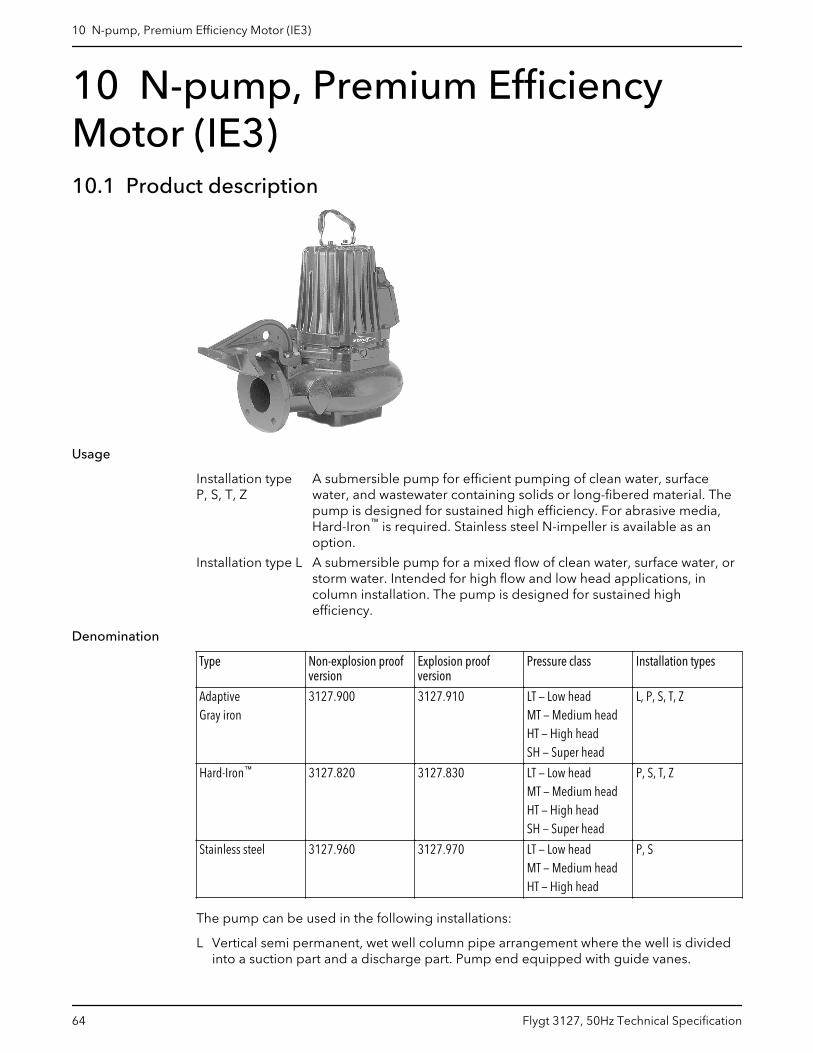
10 N-pump, Premium EfficiencyMotor (IE3)10.1 Product description
Usage
Installation typeP, S, T, Z
A submersible pump for efficient pumping of clean water, surfacewater, and wastewater containing solids or long-fibered material. Thepump is designed for sustained high efficiency. For abrasive media,Hard-Iron™ is required. Stainless steel N-impeller is available as anoption.
Installation type L A submersible pump for a mixed flow of clean water, surface water, orstorm water. Intended for high flow and low head applications, incolumn installation. The pump is designed for sustained highefficiency.
Denomination
Type Non-explosion proofversion
Explosion proofversion
Pressure class Installation types
AdaptiveGray iron
3127.900 3127.910 LT — Low headMT — Medium headHT — High headSH — Super head
L, P, S, T, Z
Hard-Iron™ 3127.820 3127.830 LT — Low headMT — Medium headHT — High headSH — Super head
P, S, T, Z
Stainless steel 3127.960 3127.970 LT — Low headMT — Medium headHT — High head
P, S
The pump can be used in the following installations:
L Vertical semi permanent, wet well column pipe arrangement where the well is dividedinto a suction part and a discharge part. Pump end equipped with guide vanes.
10 N-pump, Premium Efficiency Motor (IE3)
64 Flygt 3127, 50Hz Technical Specification
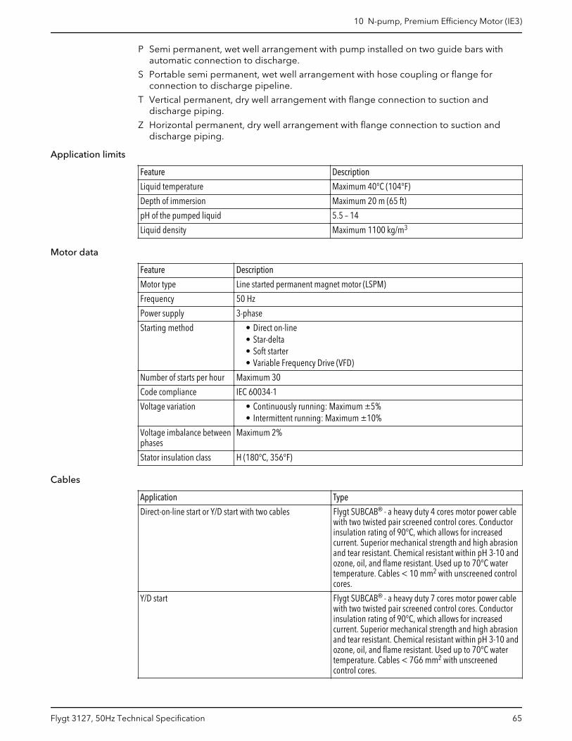
P Semi permanent, wet well arrangement with pump installed on two guide bars withautomatic connection to discharge.
S Portable semi permanent, wet well arrangement with hose coupling or flange forconnection to discharge pipeline.
T Vertical permanent, dry well arrangement with flange connection to suction anddischarge piping.
Z Horizontal permanent, dry well arrangement with flange connection to suction anddischarge piping.
Application limits
Feature Description
Liquid temperature Maximum 40°C (104°F)
Depth of immersion Maximum 20 m (65 ft)
pH of the pumped liquid 5.5 – 14
Liquid density Maximum 1100 kg/m3
Motor data
Feature Description
Motor type Line started permanent magnet motor (LSPM)
Frequency 50 Hz
Power supply 3-phase
Starting method • Direct on-line• Star-delta• Soft starter• Variable Frequency Drive (VFD)
Number of starts per hour Maximum 30
Code compliance IEC 60034-1
Voltage variation • Continuously running: Maximum ±5%• Intermittent running: Maximum ±10%
Voltage imbalance betweenphases
Maximum 2%
Stator insulation class H (180°C, 356°F)
Cables
Application Type
Direct-on-line start or Y/D start with two cables Flygt SUBCAB® - a heavy duty 4 cores motor power cablewith two twisted pair screened control cores. Conductorinsulation rating of 90°C, which allows for increasedcurrent. Superior mechanical strength and high abrasionand tear resistant. Chemical resistant within pH 3-10 andozone, oil, and flame resistant. Used up to 70°C watertemperature. Cables < 10 mm2 with unscreened controlcores.
Y/D start Flygt SUBCAB® - a heavy duty 7 cores motor power cablewith two twisted pair screened control cores. Conductorinsulation rating of 90°C, which allows for increasedcurrent. Superior mechanical strength and high abrasionand tear resistant. Chemical resistant within pH 3-10 andozone, oil, and flame resistant. Used up to 70°C watertemperature. Cables < 7G6 mm2 with unscreenedcontrol cores.
10 N-pump, Premium Efficiency Motor (IE3)
Flygt 3127, 50Hz Technical Specification 65
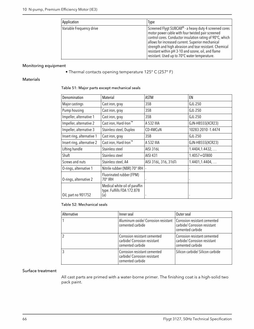
Application Type
Variable Frequency drive Screened Flygt SUBCAB® - a heavy duty 4 screened coresmotor power cable with four twisted pair screenedcontrol cores. Conductor insulation rating of 90°C, whichallows for increased current. Superior mechanicalstrength and high abrasion and tear resistant. Chemicalresistant within pH 3-10 and ozone, oil, and flameresistant. Used up to 70°C water temperature.
Monitoring equipment
• Thermal contacts opening temperature 125° C (257° F)
Materials
Table 51: Major parts except mechanical seals
Denomination Material ASTM EN
Major castings Cast iron, gray 35B GJL-250
Pump housing Cast iron, gray 35B GJL-250
Impeller, alternative 1 Cast iron, gray 35B GJL-250
Impeller, alternative 2 Cast iron, Hard-Iron™ A 532 IIIA GJN-HB555(XCR23)
Impeller, alternative 3 Stainless steel, Duplex CD-4MCuN 10283:2010 -1.4474
Insert ring, alternative 1 Cast iron, gray 35B GJL-250
Insert ring, alternative 2 Cast iron, Hard-Iron™ A 532 IIIA GJN-HB555(XCR23)
Lifting handle Stainless steel AISI 316L 1.4404,1.4432, …
Shaft Stainless steel AISI 431 1.4057+QT800
Screws and nuts Stainless steel, A4 AISI 316L, 316, 316Ti 1.4401,1.4404, …
O-rings, alternative 1 Nitrile rubber (NBR) 70° IRH - -
O-rings, alternative 2Fluorinated rubber (FPM)70° IRH - -
Oil, part no 901752
Medical white oil of paraffintype. Fulfills FDA 172.878(a) - -
Table 52: Mechanical seals
Alternative Inner seal Outer seal
1 Aluminum oxide/ Corrosion resistantcemented carbide
Corrosion resistant cementedcarbide/ Corrosion resistantcemented carbide
2 Corrosion resistant cementedcarbide/ Corrosion resistantcemented carbide
Corrosion resistant cementedcarbide/ Corrosion resistantcemented carbide
3 Corrosion resistant cementedcarbide/ Corrosion resistantcemented carbide
Silicon carbide/ Silicon carbide
Surface treatment
All cast parts are primed with a water-borne primer. The finishing coat is a high-solid twopack paint.
10 N-pump, Premium Efficiency Motor (IE3)
66 Flygt 3127, 50Hz Technical Specification
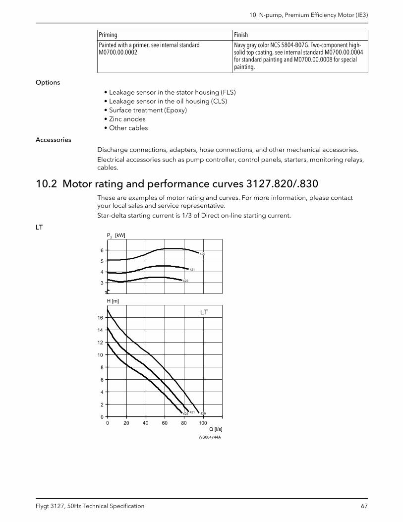
Priming Finish
Painted with a primer, see internal standardM0700.00.0002
Navy gray color NCS 5804-B07G. Two-component high-solid top coating, see internal standard M0700.00.0004for standard painting and M0700.00.0008 for specialpainting.
Options
• Leakage sensor in the stator housing (FLS)• Leakage sensor in the oil housing (CLS)• Surface treatment (Epoxy)• Zinc anodes• Other cables
Accessories
Discharge connections, adapters, hose connections, and other mechanical accessories.
Electrical accessories such as pump controller, control panels, starters, monitoring relays,cables.
10.2 Motor rating and performance curves 3127.820/.830These are examples of motor rating and curves. For more information, please contactyour local sales and service representative.
Star-delta starting current is 1/3 of Direct on-line starting current.
LT
Q [l/s]
H [m]
2P [kW]
0 20 40 60 80 1000
2
4
6
8
10
12
14
16
3
4
5
6
LT
420
420
421
421
421
421
421
421
422
422
422
422
422
422
WS004744A
10 N-pump, Premium Efficiency Motor (IE3)
Flygt 3127, 50Hz Technical Specification 67
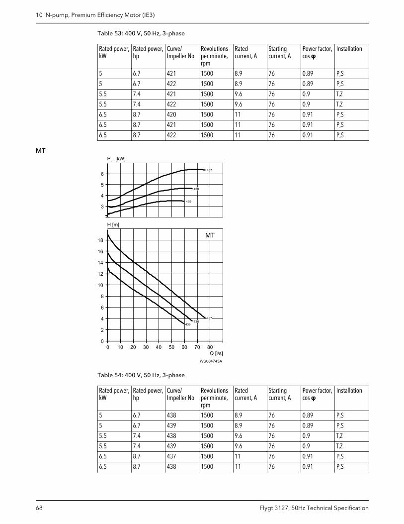
Table 53: 400 V, 50 Hz, 3–phase
Rated power,kW
Rated power,hp
Curve/Impeller No
Revolutionsper minute,rpm
Ratedcurrent, A
Startingcurrent, A
Power factor,cos φ
Installation
5 6.7 421 1500 8.9 76 0.89 P,S
5 6.7 422 1500 8.9 76 0.89 P,S
5.5 7.4 421 1500 9.6 76 0.9 T,Z
5.5 7.4 422 1500 9.6 76 0.9 T,Z
6.5 8.7 420 1500 11 76 0.91 P,S
6.5 8.7 421 1500 11 76 0.91 P,S
6.5 8.7 422 1500 11 76 0.91 P,S
MT
Q [l/s]
H [m]
2P [kW]
0 10 20 30 40 50 60 70 800
2
4
6
8
10
12
14
16
18
3
4
5
6
MT
437
437
438
438
439
439
WS004745A
Table 54: 400 V, 50 Hz, 3–phase
Rated power,kW
Rated power,hp
Curve/Impeller No
Revolutionsper minute,rpm
Ratedcurrent, A
Startingcurrent, A
Power factor,cos φ
Installation
5 6.7 438 1500 8.9 76 0.89 P,S
5 6.7 439 1500 8.9 76 0.89 P,S
5.5 7.4 438 1500 9.6 76 0.9 T,Z
5.5 7.4 439 1500 9.6 76 0.9 T,Z
6.5 8.7 437 1500 11 76 0.91 P,S
6.5 8.7 438 1500 11 76 0.91 P,S
10 N-pump, Premium Efficiency Motor (IE3)
68 Flygt 3127, 50Hz Technical Specification
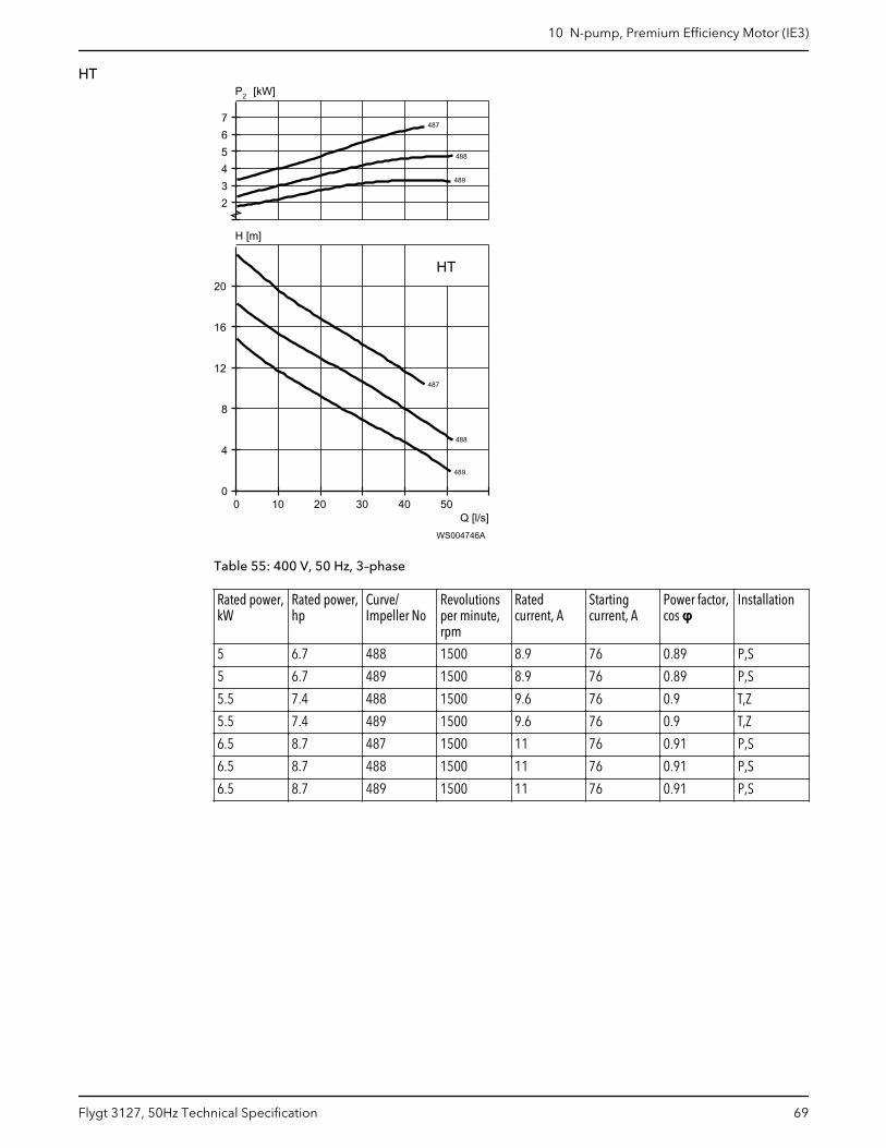
HT
Q [l/s]
H [m]
2P [kW]
0 10 20 30 40 500
4
8
12
16
20
234567
HT
487
487
488
488
489
489
WS004746A
Table 55: 400 V, 50 Hz, 3–phase
Rated power,kW
Rated power,hp
Curve/Impeller No
Revolutionsper minute,rpm
Ratedcurrent, A
Startingcurrent, A
Power factor,cos φ
Installation
5 6.7 488 1500 8.9 76 0.89 P,S
5 6.7 489 1500 8.9 76 0.89 P,S
5.5 7.4 488 1500 9.6 76 0.9 T,Z
5.5 7.4 489 1500 9.6 76 0.9 T,Z
6.5 8.7 487 1500 11 76 0.91 P,S
6.5 8.7 488 1500 11 76 0.91 P,S
6.5 8.7 489 1500 11 76 0.91 P,S
10 N-pump, Premium Efficiency Motor (IE3)
Flygt 3127, 50Hz Technical Specification 69
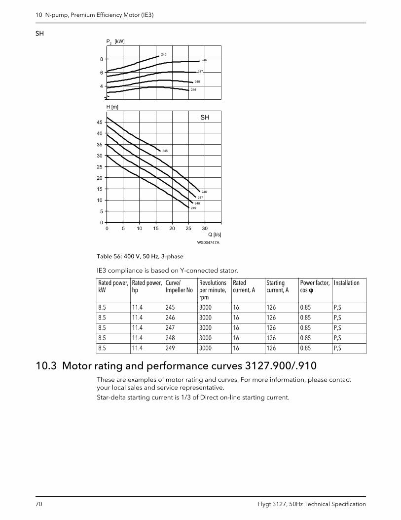
SH
Q [l/s]
H [m]
2P [kW]
0 5 10 15 20 25 300
5
10
15
20
25
30
35
40
45
4
6
8
SH
245
245
246
246
247
247
248
248
249
249
WS004747A
Table 56: 400 V, 50 Hz, 3–phase
IE3 compliance is based on Y-connected stator.
Rated power,kW
Rated power,hp
Curve/Impeller No
Revolutionsper minute,rpm
Ratedcurrent, A
Startingcurrent, A
Power factor,cos φ
Installation
8.5 11.4 245 3000 16 126 0.85 P,S
8.5 11.4 246 3000 16 126 0.85 P,S
8.5 11.4 247 3000 16 126 0.85 P,S
8.5 11.4 248 3000 16 126 0.85 P,S
8.5 11.4 249 3000 16 126 0.85 P,S
10.3 Motor rating and performance curves 3127.900/.910These are examples of motor rating and curves. For more information, please contactyour local sales and service representative.
Star-delta starting current is 1/3 of Direct on-line starting current.
10 N-pump, Premium Efficiency Motor (IE3)
70 Flygt 3127, 50Hz Technical Specification
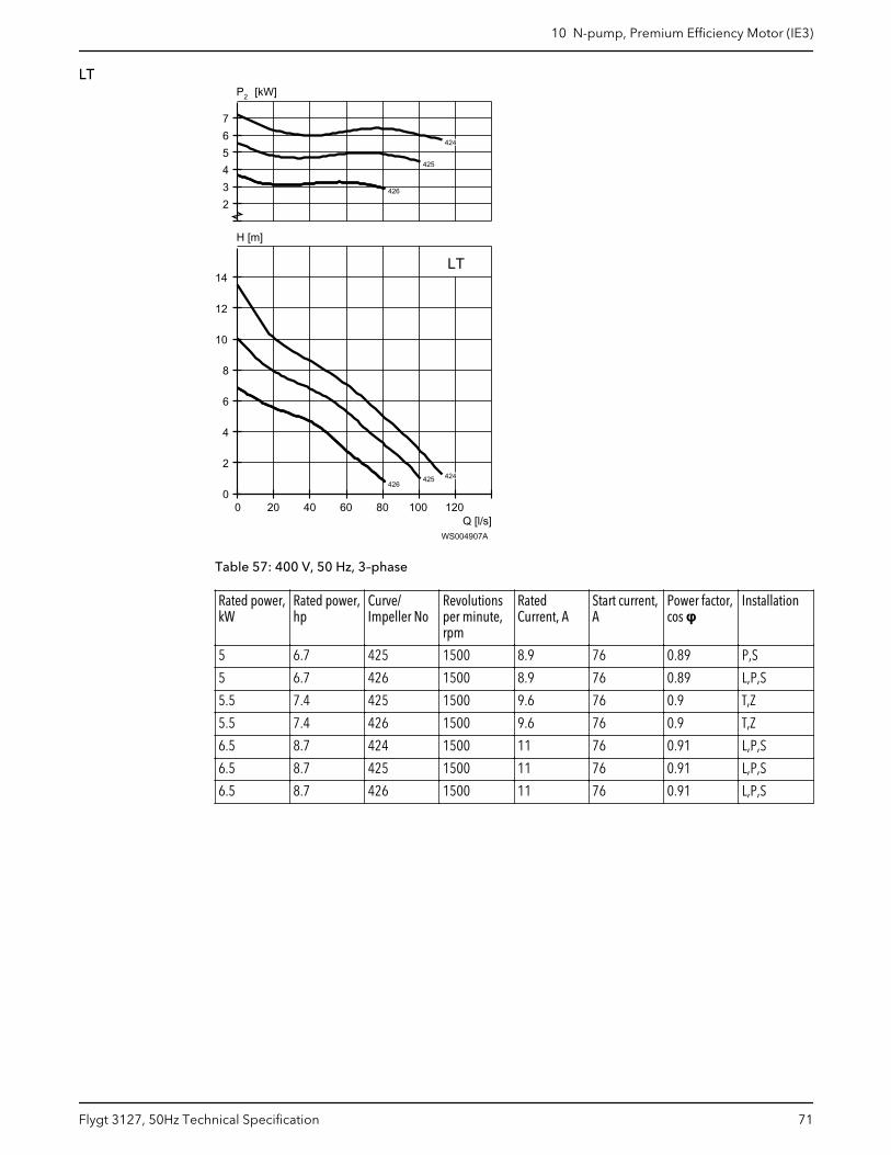
LT
Q [l/s]
H [m]
2P [kW]
0 20 40 60 80 100 1200
2
4
6
8
10
12
14
234567
LT
424
424
425
425
426426
426
WS004907A
Table 57: 400 V, 50 Hz, 3–phase
Rated power,kW
Rated power,hp
Curve/Impeller No
Revolutionsper minute,rpm
RatedCurrent, A
Start current,A
Power factor,cos φ
Installation
5 6.7 425 1500 8.9 76 0.89 P,S
5 6.7 426 1500 8.9 76 0.89 L,P,S
5.5 7.4 425 1500 9.6 76 0.9 T,Z
5.5 7.4 426 1500 9.6 76 0.9 T,Z
6.5 8.7 424 1500 11 76 0.91 L,P,S
6.5 8.7 425 1500 11 76 0.91 L,P,S
6.5 8.7 426 1500 11 76 0.91 L,P,S
10 N-pump, Premium Efficiency Motor (IE3)
Flygt 3127, 50Hz Technical Specification 71
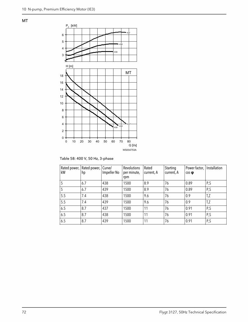
MT
Q [l/s]
H [m]
2P [kW]
0 10 20 30 40 50 60 70 800
2
4
6
8
10
12
14
16
18
3
4
5
6
MT
437
437
438
438
438
438
438
438
439
439
439
439
439
439
WS004753A
Table 58: 400 V, 50 Hz, 3–phase
Rated power,kW
Rated power,hp
Curve/Impeller No
Revolutionsper minute,rpm
Ratedcurrent, A
Startingcurrent, A
Power factor,cos φ
Installation
5 6.7 438 1500 8.9 76 0.89 P,S
5 6.7 439 1500 8.9 76 0.89 P,S
5.5 7.4 438 1500 9.6 76 0.9 T,Z
5.5 7.4 439 1500 9.6 76 0.9 T,Z
6.5 8.7 437 1500 11 76 0.91 P,S
6.5 8.7 438 1500 11 76 0.91 P,S
6.5 8.7 439 1500 11 76 0.91 P,S
10 N-pump, Premium Efficiency Motor (IE3)
72 Flygt 3127, 50Hz Technical Specification
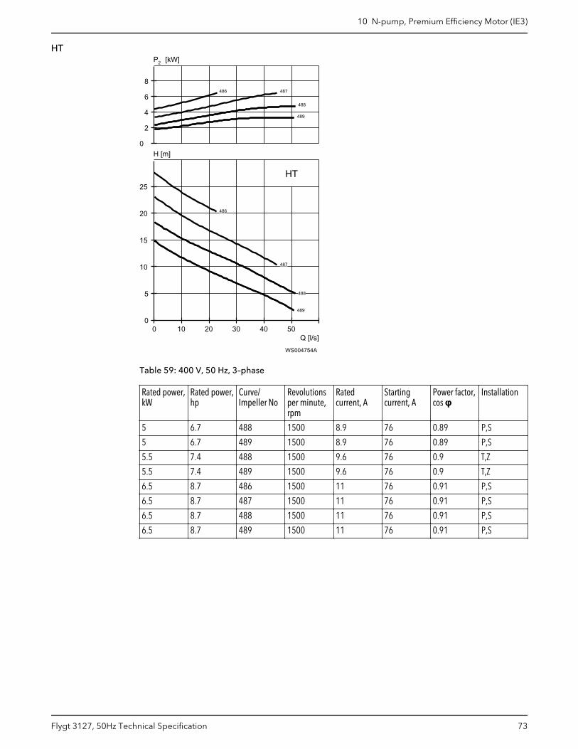
HT
Q [l/s]
H [m]
2P [kW]
0 10 20 30 40 500
5
10
15
20
25
0
2
4
6
8
HT
486
486
487
487
488
488
488
488
488
488
489
489
489
489
489
489
WS004754A
Table 59: 400 V, 50 Hz, 3–phase
Rated power,kW
Rated power,hp
Curve/Impeller No
Revolutionsper minute,rpm
Ratedcurrent, A
Startingcurrent, A
Power factor,cos φ
Installation
5 6.7 488 1500 8.9 76 0.89 P,S
5 6.7 489 1500 8.9 76 0.89 P,S
5.5 7.4 488 1500 9.6 76 0.9 T,Z
5.5 7.4 489 1500 9.6 76 0.9 T,Z
6.5 8.7 486 1500 11 76 0.91 P,S
6.5 8.7 487 1500 11 76 0.91 P,S
6.5 8.7 488 1500 11 76 0.91 P,S
6.5 8.7 489 1500 11 76 0.91 P,S
10 N-pump, Premium Efficiency Motor (IE3)
Flygt 3127, 50Hz Technical Specification 73

SH
Q [l/s]
H [m]
2P [kW]
0 5 10 15 20 25 300
5
10
15
20
25
30
35
40
45
4
6
8
SH
245
245
245
245
246
246
246
246
247
247
247
247
248
248
248
248
249
249
249
249
WS004755A
Table 60: 400 V, 50 Hz, 3–phase
IE3 compliance is based on Y-connected stator.
Rated power,kW
Rated power,hp
Curve/Impeller No
Revolutionsper minute,rpm
Ratedcurrent, A
Startingcurrent, A
Power factor,cos φ
Installation
8.5 11.4 245 3000 16 126 0.85 P,S
8.5 11.4 246 3000 16 126 0.85 P,S
8.5 11.4 247 3000 16 126 0.85 P,S
8.5 11.4 248 3000 16 126 0.85 P,S
8.5 11.4 249 3000 16 126 0.85 P,S
10.4 Motor rating and performance curves 3127.960/.970These are examples of motor rating and curves. For more information, please contactyour local sales and service representative.
Star-delta starting current is 1/3 of Direct on-line starting current.
10 N-pump, Premium Efficiency Motor (IE3)
74 Flygt 3127, 50Hz Technical Specification
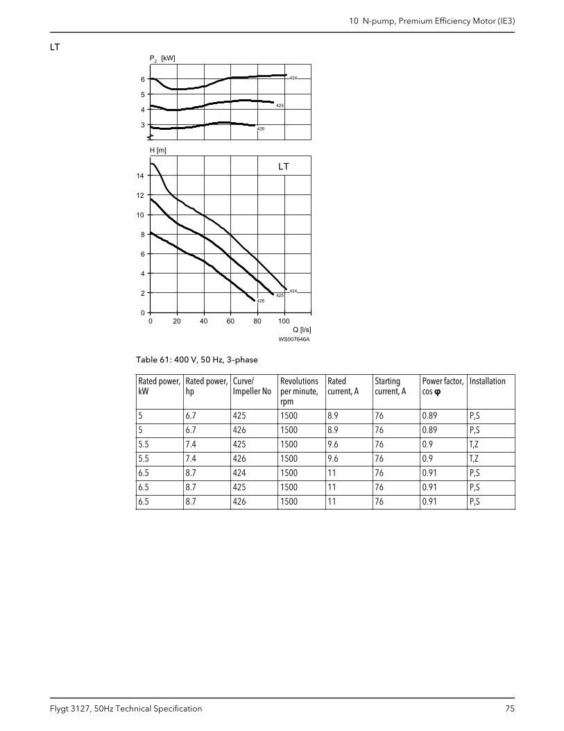
LT
Q [l/s]
H [m]
2P [kW]
0 20 40 60 80 1000
2
4
6
8
10
12
14
3
4
5
6
LT
424
424
424
424
425
425
425
425
425
425
425
425
425
425
425
425
426
426
426
426
426
426
426
426
426
426
426
426
WS007646A
Table 61: 400 V, 50 Hz, 3–phase
Rated power,kW
Rated power,hp
Curve/Impeller No
Revolutionsper minute,rpm
Ratedcurrent, A
Startingcurrent, A
Power factor,cos φ
Installation
5 6.7 425 1500 8.9 76 0.89 P,S
5 6.7 426 1500 8.9 76 0.89 P,S
5.5 7.4 425 1500 9.6 76 0.9 T,Z
5.5 7.4 426 1500 9.6 76 0.9 T,Z
6.5 8.7 424 1500 11 76 0.91 P,S
6.5 8.7 425 1500 11 76 0.91 P,S
6.5 8.7 426 1500 11 76 0.91 P,S
10 N-pump, Premium Efficiency Motor (IE3)
Flygt 3127, 50Hz Technical Specification 75
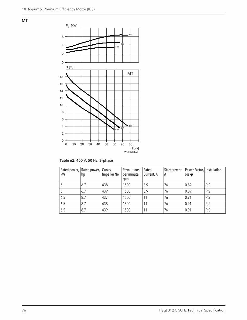
MT
Q [l/s]
H [m]
2P [kW]
0 10 20 30 40 50 60 70 800
2
4
6
8
10
12
14
16
18
0
2
4
6
MT
437
437
437
437
437
437
437
437
437
437
438
438
438
438
438
438
438
438
438
438
438
438
438
438
438
438
438
438
438
438
438
438
438
438
438
438
438
438
438
438
439
439
439
439
439
439
439
439
439
439
439
439
439
439
439
439
439
439
439
439
439
439
439
439
439
439
439
439
439
439
WS007647A
Table 62: 400 V, 50 Hz, 3–phase
Rated power,kW
Rated power,hp
Curve/Impeller No
Revolutionsper minute,rpm
RatedCurrent, A
Start current,A
Power Factor,cos φ
Installation
5 6.7 438 1500 8.9 76 0.89 P,S
5 6.7 439 1500 8.9 76 0.89 P,S
6.5 8.7 437 1500 11 76 0.91 P,S
6.5 8.7 438 1500 11 76 0.91 P,S
6.5 8.7 439 1500 11 76 0.91 P,S
10 N-pump, Premium Efficiency Motor (IE3)
76 Flygt 3127, 50Hz Technical Specification
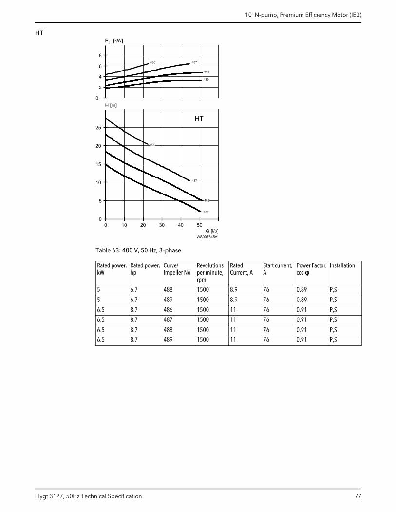
HT
Q [l/s]
H [m]
2P [kW]
0 10 20 30 40 500
5
10
15
20
25
0
2
4
6
8
HT
486
486
486
486
486
486
487
487
487
487
487
487
488
488
488
488
488
488
488
488
488
488
488
488
488
488
488
488
488
488
489
489
489
489
489
489
489
489
489
489
489
489
489
489
489
489
489
489
WS007645A
Table 63: 400 V, 50 Hz, 3–phase
Rated power,kW
Rated power,hp
Curve/Impeller No
Revolutionsper minute,rpm
RatedCurrent, A
Start current,A
Power Factor,cos φ
Installation
5 6.7 488 1500 8.9 76 0.89 P,S
5 6.7 489 1500 8.9 76 0.89 P,S
6.5 8.7 486 1500 11 76 0.91 P,S
6.5 8.7 487 1500 11 76 0.91 P,S
6.5 8.7 488 1500 11 76 0.91 P,S
6.5 8.7 489 1500 11 76 0.91 P,S
10 N-pump, Premium Efficiency Motor (IE3)
Flygt 3127, 50Hz Technical Specification 77
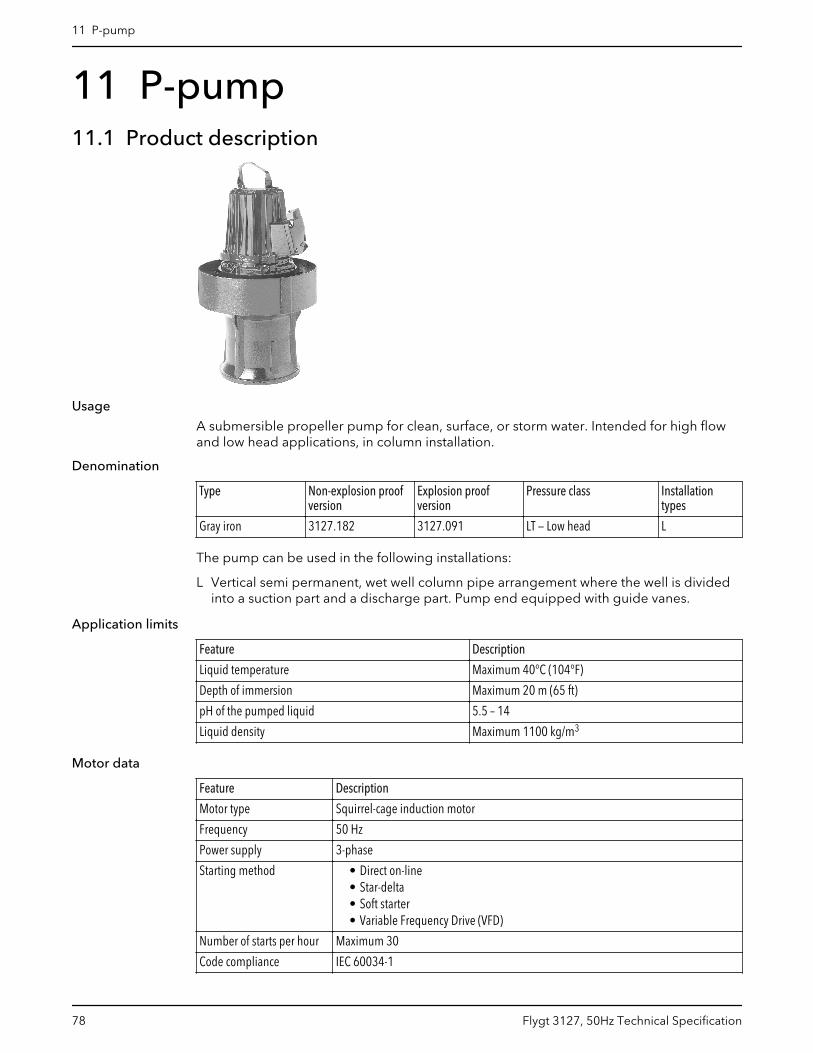
11 P-pump11.1 Product description
Usage
A submersible propeller pump for clean, surface, or storm water. Intended for high flowand low head applications, in column installation.
Denomination
Type Non-explosion proofversion
Explosion proofversion
Pressure class Installationtypes
Gray iron 3127.182 3127.091 LT — Low head L
The pump can be used in the following installations:
L Vertical semi permanent, wet well column pipe arrangement where the well is dividedinto a suction part and a discharge part. Pump end equipped with guide vanes.
Application limits
Feature Description
Liquid temperature Maximum 40°C (104°F)
Depth of immersion Maximum 20 m (65 ft)
pH of the pumped liquid 5.5 – 14
Liquid density Maximum 1100 kg/m3
Motor data
Feature Description
Motor type Squirrel-cage induction motor
Frequency 50 Hz
Power supply 3-phase
Starting method • Direct on-line• Star-delta• Soft starter• Variable Frequency Drive (VFD)
Number of starts per hour Maximum 30
Code compliance IEC 60034-1
11 P-pump
78 Flygt 3127, 50Hz Technical Specification
Feature Description
Voltage variation • Continuously running: Maximum ±5%• Intermittent running: Maximum ±10%
Voltage imbalance betweenphases
Maximum 2%
Stator insulation class H (180°C, 356°F)
Cables
Application Type
Direct-on-line start or Y/D start with two cables Flygt SUBCAB® - a heavy duty 4 cores motor power cablewith two twisted pair screened control cores. Conductorinsulation rating of 90°C, which allows for increasedcurrent. Superior mechanical strength and high abrasionand tear resistant. Chemical resistant within pH 3-10 andozone, oil, and flame resistant. Used up to 70°C watertemperature. Cables < 10 mm2 with unscreened controlcores.
Y/D start Flygt SUBCAB® - a heavy duty 7 cores motor power cablewith two twisted pair screened control cores. Conductorinsulation rating of 90°C, which allows for increasedcurrent. Superior mechanical strength and high abrasionand tear resistant. Chemical resistant within pH 3-10 andozone, oil, and flame resistant. Used up to 70°C watertemperature. Cables < 7G6 mm2 with unscreenedcontrol cores.
Variable Frequency drive Screened Flygt SUBCAB® - a heavy duty 4 screened coresmotor power cable with four twisted pair screenedcontrol cores. Conductor insulation rating of 90°C, whichallows for increased current. Superior mechanicalstrength and high abrasion and tear resistant. Chemicalresistant within pH 3-10 and ozone, oil, and flameresistant. Used up to 70°C water temperature.
Monitoring equipment
• Thermal contacts opening temperature 125° C (257° F)
Materials
Table 64: Major parts except mechanical seals
Denomination Material ASTM EN
Major castings Cast iron, gray 35B GJL-250
Pump housing Cast iron, gray 35B GJL-250
Propeller Aluminum bronze C 95 500 CC333G
Lifting handle Stainless steel AISI 316L 1.4404,1.4432, …
Shaft Stainless steel AISI 431 1.4057+QT800
Screws and nuts Stainless steel, A4 AISI 316L, 316, 316Ti 1.4401,1.4404, …
O-rings, alternative 1 Nitrile rubber (NBR) 70° IRH - -
O-rings, alternative 2 Fluorinated rubber (FPM)70° IRH
- -
Oil Part No 901752 Medical white oil of paraffintype. Fulfills FDA 172.878(a)
- -
11 P-pump
Flygt 3127, 50Hz Technical Specification 79
Table 65: Mechanical seals
Alternative Inner seal Outer seal
1 Aluminum oxide/ Corrosion resistantcemented carbide
Corrosion resistant cementedcarbide/ Corrosion resistantcemented carbide
2 Corrosion resistant cementedcarbide/ Corrosion resistantcemented carbide
Corrosion resistant cementedcarbide/ Corrosion resistantcemented carbide
3 Corrosion resistant cementedcarbide/ Corrosion resistantcemented carbide
Silicon carbide/ Silicon carbide
Surface treatment
Priming Finish
Painted with a primer, see internal standardM0700.00.0002
Navy gray color NCS 5804-B07G. Two-component high-solid top coating, see internal standard M0700.00.0004for standard painting and M0700.00.0008 for specialpainting.
Options
• Leakage sensor in the stator housing (FLS)• Leakage sensor in the oil housing (CLS)• Surface treatment (Epoxy)• Zinc anodes• Other cables
Accessories
Discharge connections, adapters, hose connections, and other mechanical accessories.
Electrical accessories such as pump controller, control panels, starters, monitoring relays,cables.
11.2 Motor rating and performance curvesThese are examples of motor rating and curves. For more information, please contactyour local sales and service representative.
Star-delta starting current is 1/3 of Direct on-line starting current.
11 P-pump
80 Flygt 3127, 50Hz Technical Specification
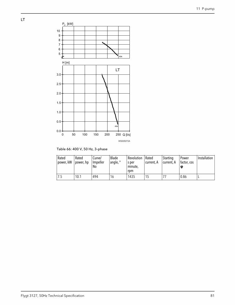
LT
WS005072A
Table 66: 400 V, 50 Hz, 3–phase
Ratedpower, kW
Ratedpower, hp
Curve/ImpellerNo
Bladeangle, °
Revolutions perminute,rpm
Ratedcurrent, A
Startingcurrent, A
Powerfactor, cosφ
Installation
7.5 10.1 494 16 1435 15 77 0.86 L
11 P-pump
Flygt 3127, 50Hz Technical Specification 81
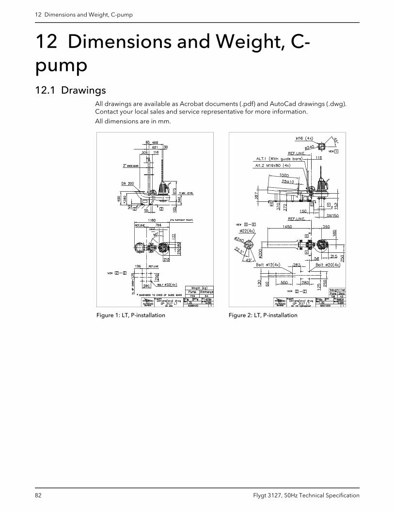
12 Dimensions and Weight, C-pump12.1 Drawings
All drawings are available as Acrobat documents (.pdf) and AutoCad drawings (.dwg).Contact your local sales and service representative for more information.
All dimensions are in mm.
Figure 1: LT, P-installation Figure 2: LT, P-installation
12 Dimensions and Weight, C-pump
82 Flygt 3127, 50Hz Technical Specification
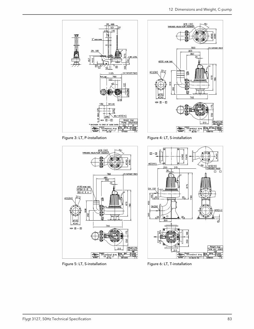
Figure 3: LT, P-installation Figure 4: LT, S-installation
Figure 5: LT, S-installation Figure 6: LT, T-installation
12 Dimensions and Weight, C-pump
Flygt 3127, 50Hz Technical Specification 83
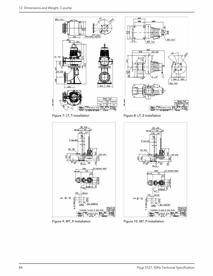
Figure 7: LT, T-installation Figure 8: LT, Z-installation
Figure 9: MT, P-installation Figure 10: MT, P-installation
12 Dimensions and Weight, C-pump
84 Flygt 3127, 50Hz Technical Specification
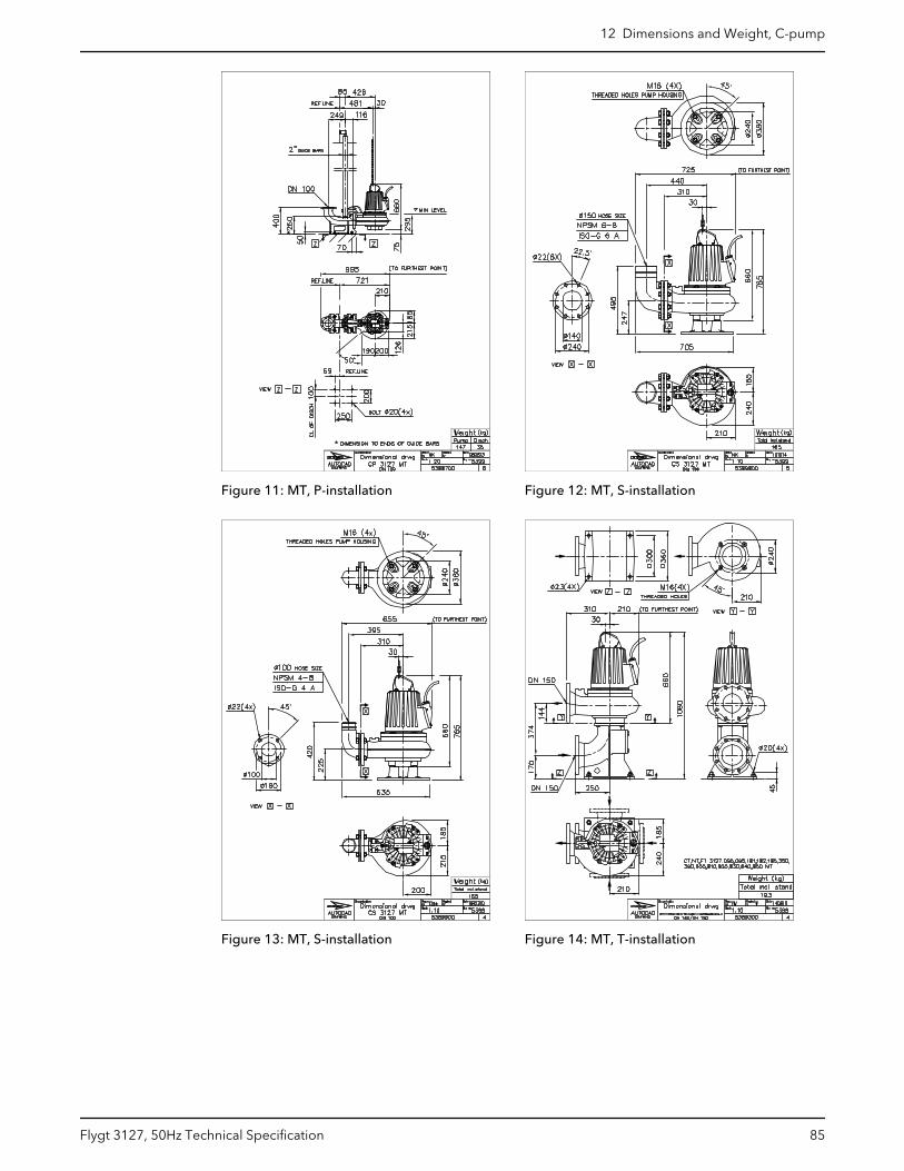
Figure 11: MT, P-installation Figure 12: MT, S-installation
Figure 13: MT, S-installation Figure 14: MT, T-installation
12 Dimensions and Weight, C-pump
Flygt 3127, 50Hz Technical Specification 85
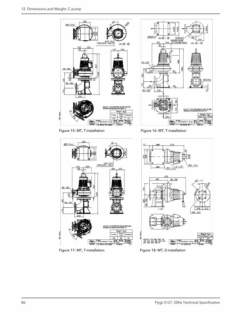
Figure 15: MT, T-installation Figure 16: MT, T-installation
Figure 17: MT, T-installation Figure 18: MT, Z-installation
12 Dimensions and Weight, C-pump
86 Flygt 3127, 50Hz Technical Specification
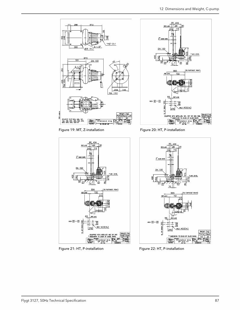
Figure 19: MT, Z-installation Figure 20: HT, P-installation
Figure 21: HT, P-installation Figure 22: HT, P-installation
12 Dimensions and Weight, C-pump
Flygt 3127, 50Hz Technical Specification 87
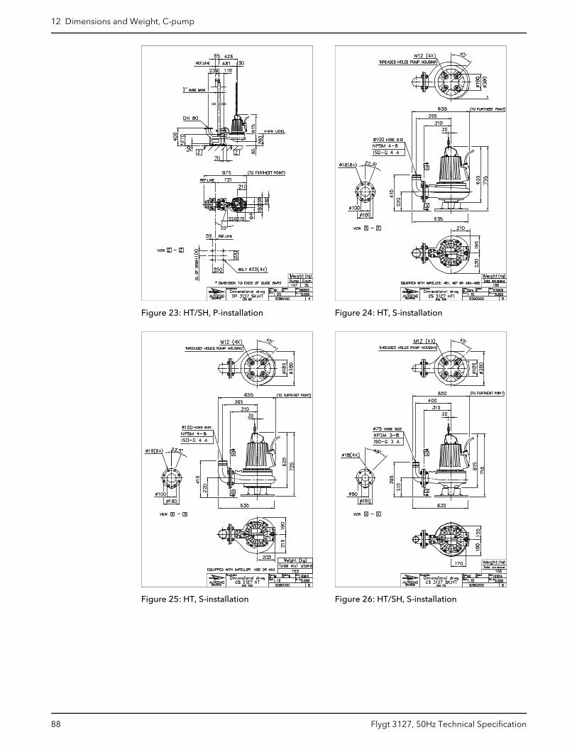
Figure 23: HT/SH, P-installation Figure 24: HT, S-installation
Figure 25: HT, S-installation Figure 26: HT/SH, S-installation
12 Dimensions and Weight, C-pump
88 Flygt 3127, 50Hz Technical Specification
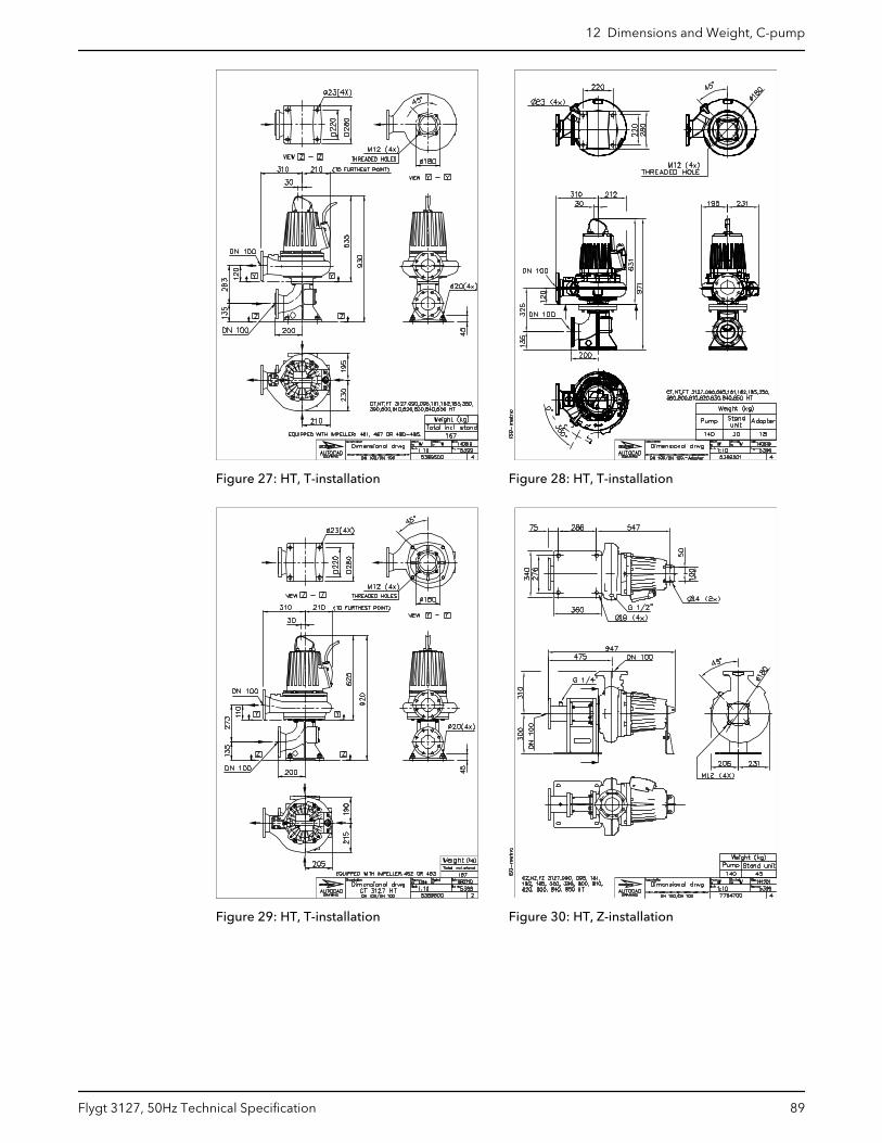
Figure 27: HT, T-installation Figure 28: HT, T-installation
Figure 29: HT, T-installation Figure 30: HT, Z-installation
12 Dimensions and Weight, C-pump
Flygt 3127, 50Hz Technical Specification 89
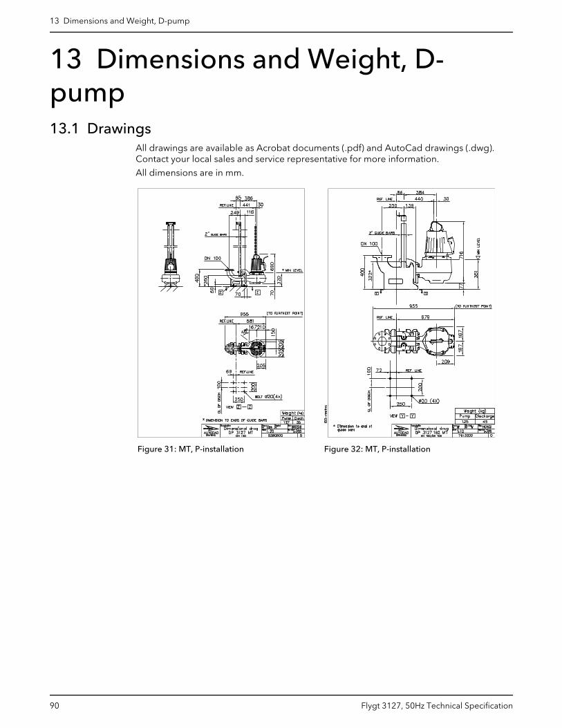
13 Dimensions and Weight, D-pump13.1 Drawings
All drawings are available as Acrobat documents (.pdf) and AutoCad drawings (.dwg).Contact your local sales and service representative for more information.
All dimensions are in mm.
Figure 31: MT, P-installation Figure 32: MT, P-installation
13 Dimensions and Weight, D-pump
90 Flygt 3127, 50Hz Technical Specification
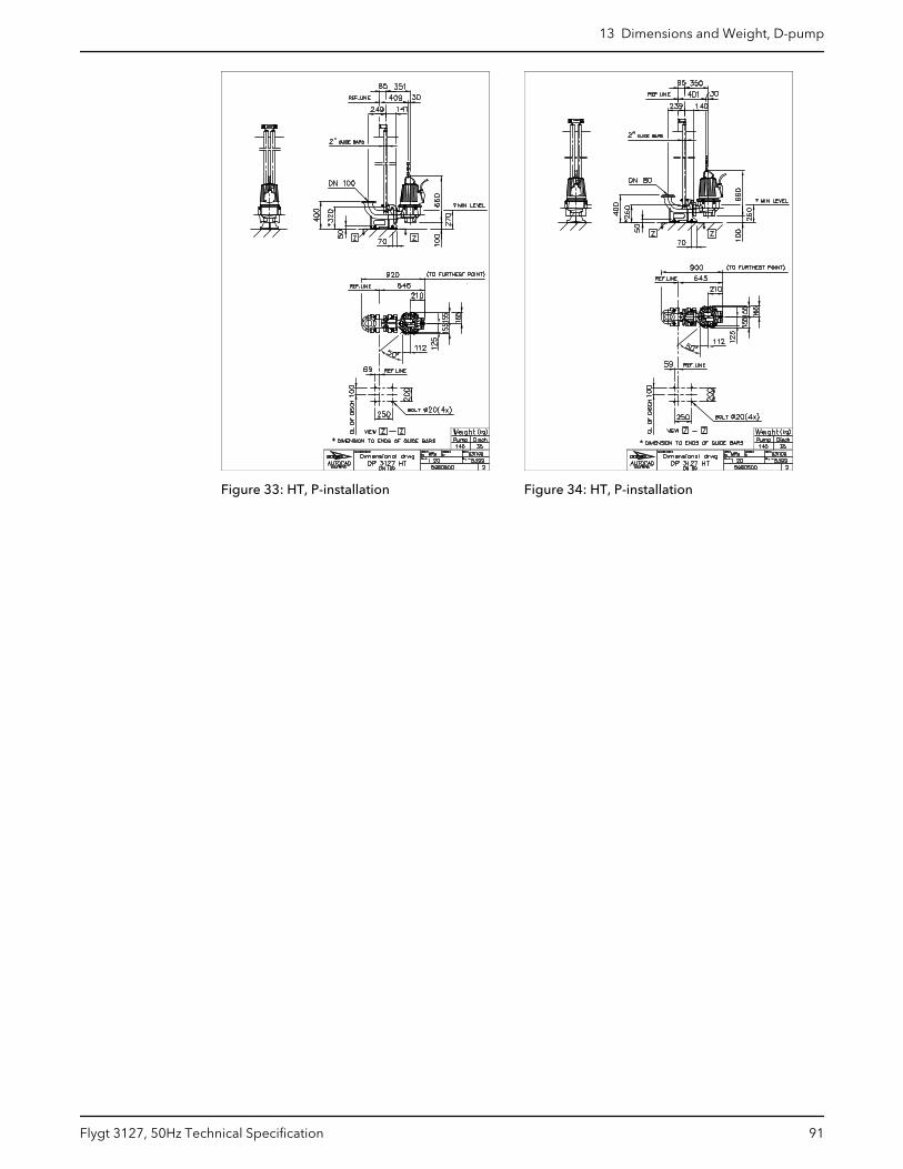
Figure 33: HT, P-installation Figure 34: HT, P-installation
13 Dimensions and Weight, D-pump
Flygt 3127, 50Hz Technical Specification 91
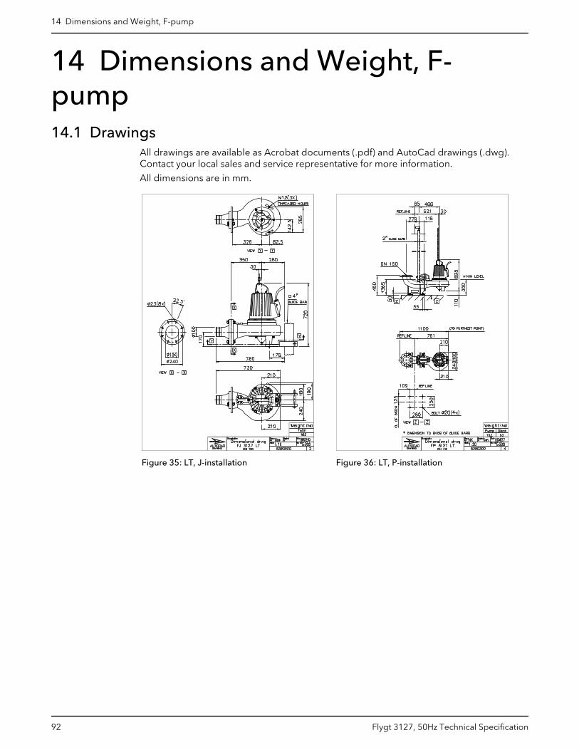
14 Dimensions and Weight, F-pump14.1 Drawings
All drawings are available as Acrobat documents (.pdf) and AutoCad drawings (.dwg).Contact your local sales and service representative for more information.
All dimensions are in mm.
Figure 35: LT, J-installation Figure 36: LT, P-installation
14 Dimensions and Weight, F-pump
92 Flygt 3127, 50Hz Technical Specification
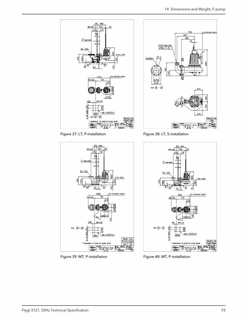
Figure 37: LT, P-installation Figure 38: LT, S-installation
Figure 39: MT, P-installation Figure 40: MT, P-installation
14 Dimensions and Weight, F-pump
Flygt 3127, 50Hz Technical Specification 93
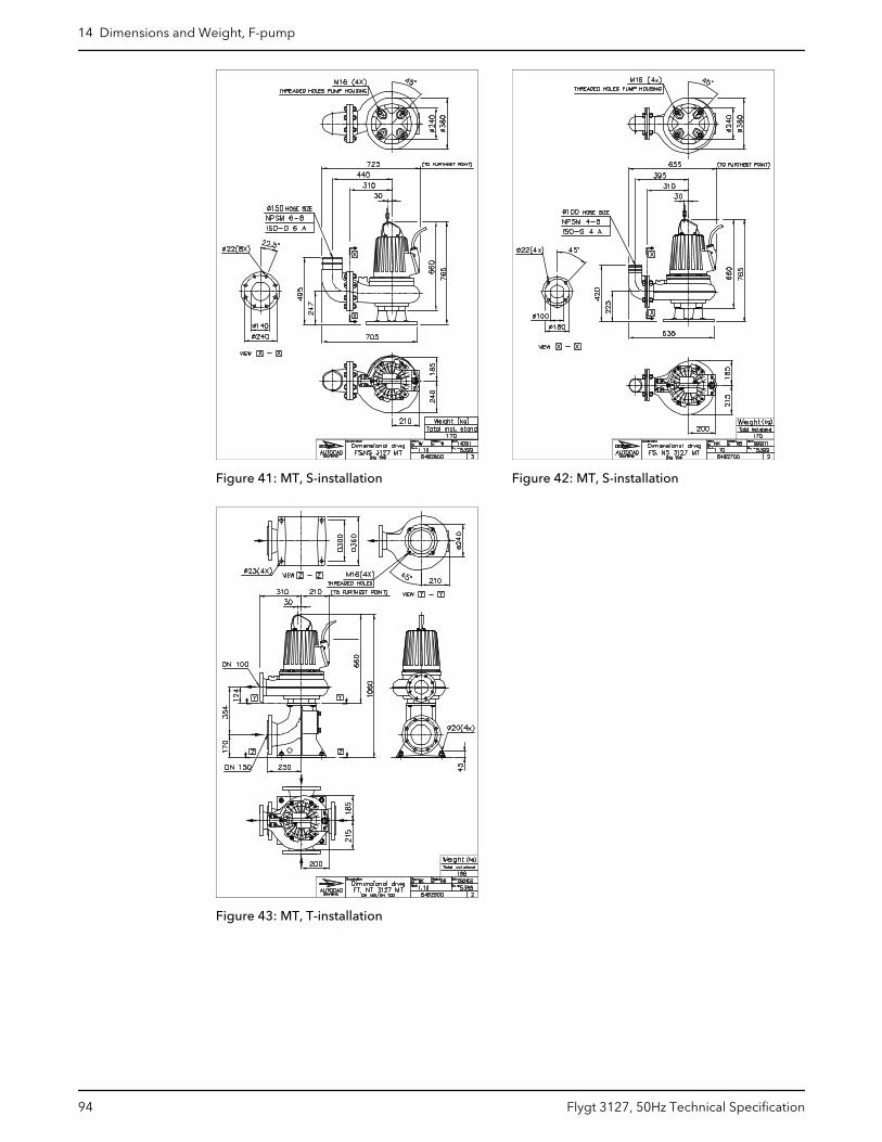
Figure 41: MT, S-installation Figure 42: MT, S-installation
Figure 43: MT, T-installation
14 Dimensions and Weight, F-pump
94 Flygt 3127, 50Hz Technical Specification
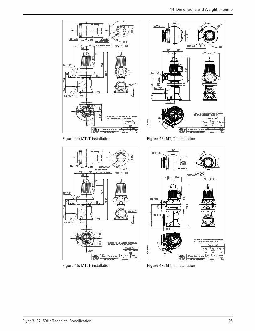
Figure 44: MT, T-installation Figure 45: MT, T-installation
Figure 46: MT, T-installation Figure 47: MT, T-installation
14 Dimensions and Weight, F-pump
Flygt 3127, 50Hz Technical Specification 95
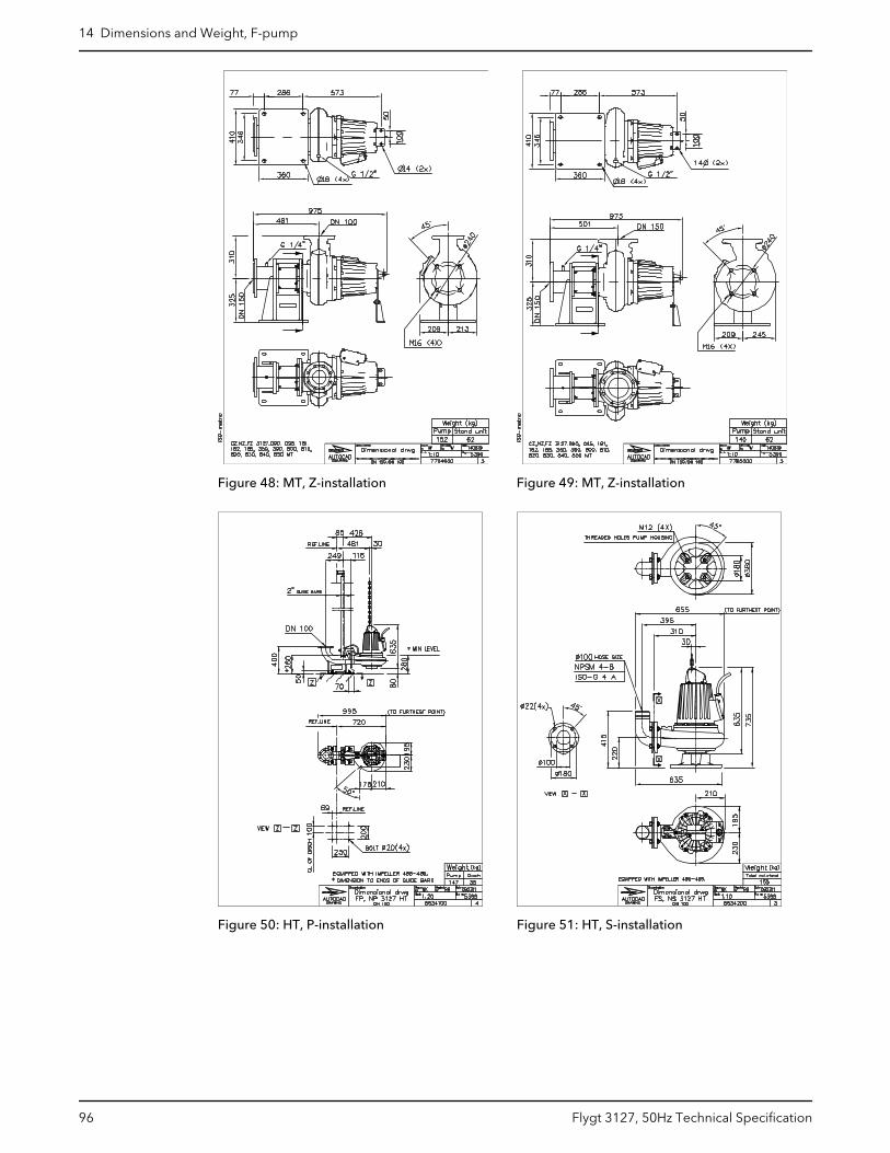
Figure 48: MT, Z-installation Figure 49: MT, Z-installation
Figure 50: HT, P-installation Figure 51: HT, S-installation
14 Dimensions and Weight, F-pump
96 Flygt 3127, 50Hz Technical Specification
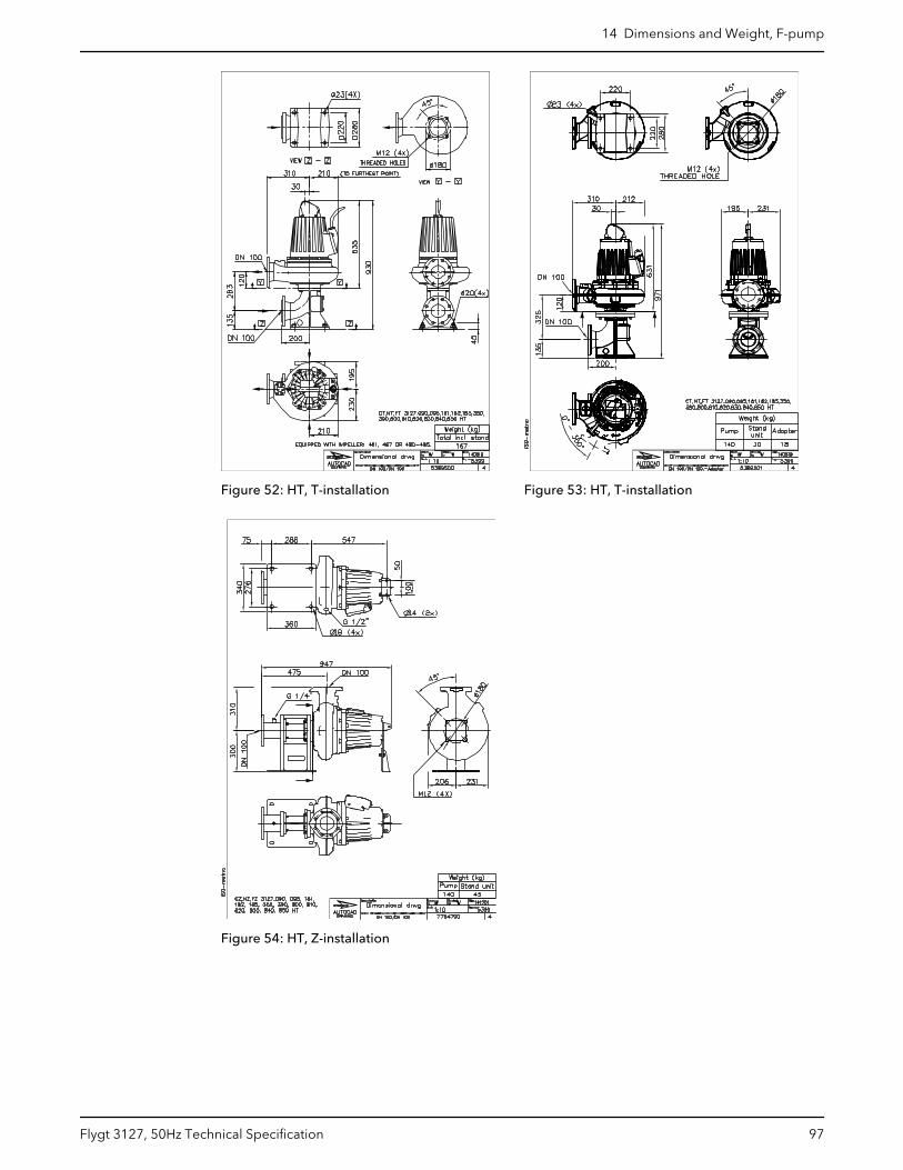
Figure 52: HT, T-installation Figure 53: HT, T-installation
Figure 54: HT, Z-installation
14 Dimensions and Weight, F-pump
Flygt 3127, 50Hz Technical Specification 97
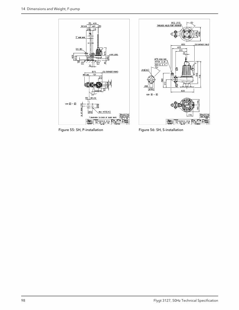
Figure 55: SH, P-installation Figure 56: SH, S-installation
14 Dimensions and Weight, F-pump
98 Flygt 3127, 50Hz Technical Specification
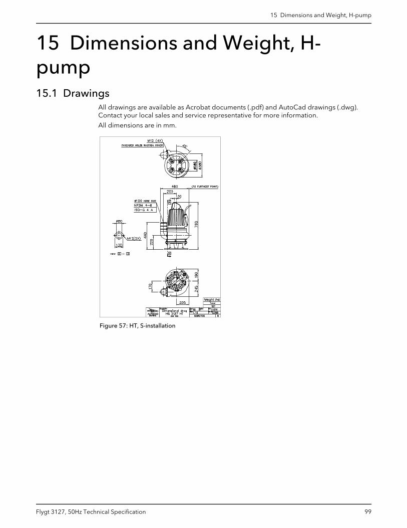
15 Dimensions and Weight, H-pump15.1 Drawings
All drawings are available as Acrobat documents (.pdf) and AutoCad drawings (.dwg).Contact your local sales and service representative for more information.
All dimensions are in mm.
Figure 57: HT, S-installation
15 Dimensions and Weight, H-pump
Flygt 3127, 50Hz Technical Specification 99

16 Dimensions and Weight, M-pump16.1 Drawings
All drawings are available as Acrobat documents (.pdf) and AutoCad drawings (.dwg).Contact your local sales and service representative for more information.
All dimensions are in mm.
Figure 58: LT/HT, F-installation Figure 59: LT/HT, P-installation
16 Dimensions and Weight, M-pump
100 Flygt 3127, 50Hz Technical Specification
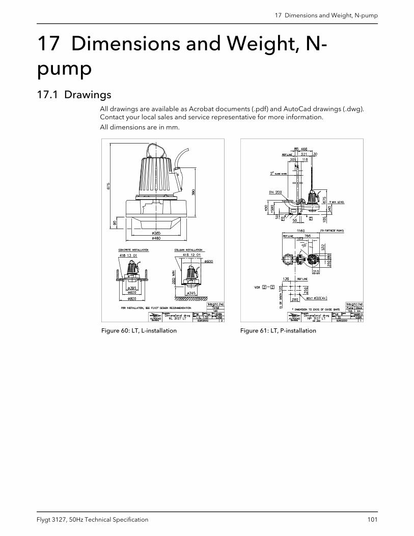
17 Dimensions and Weight, N-pump17.1 Drawings
All drawings are available as Acrobat documents (.pdf) and AutoCad drawings (.dwg).Contact your local sales and service representative for more information.
All dimensions are in mm.
Figure 60: LT, L-installation Figure 61: LT, P-installation
17 Dimensions and Weight, N-pump
Flygt 3127, 50Hz Technical Specification 101
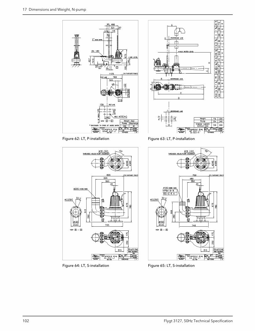
Figure 62: LT, P-installation Figure 63: LT, P-installation
Figure 64: LT, S-installation Figure 65: LT, S-installation
17 Dimensions and Weight, N-pump
102 Flygt 3127, 50Hz Technical Specification
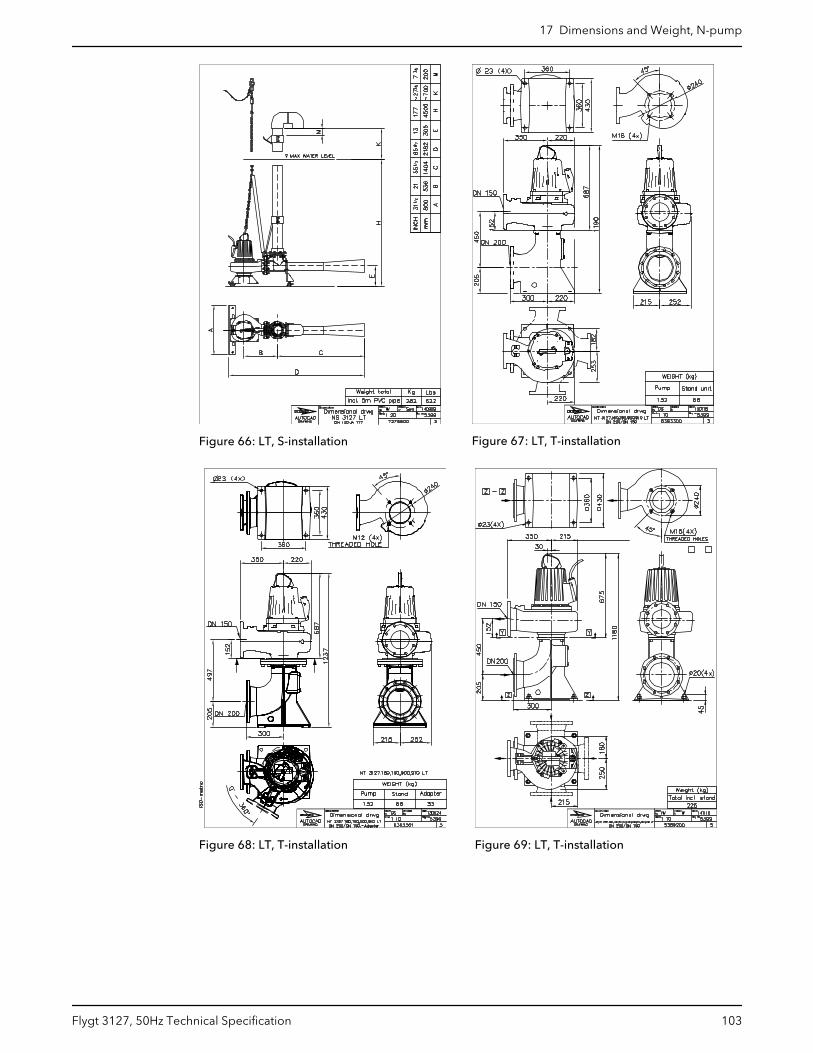
Figure 66: LT, S-installation Figure 67: LT, T-installation
Figure 68: LT, T-installation Figure 69: LT, T-installation
17 Dimensions and Weight, N-pump
Flygt 3127, 50Hz Technical Specification 103
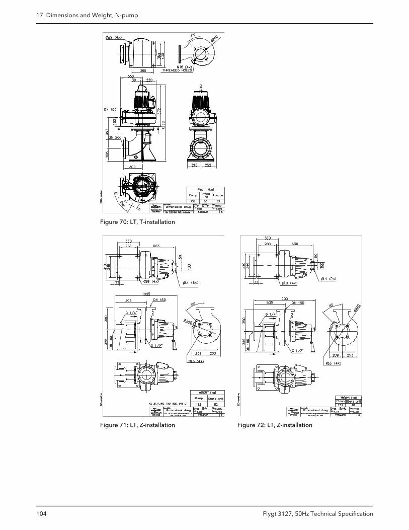
Figure 70: LT, T-installation
Figure 71: LT, Z-installation Figure 72: LT, Z-installation
17 Dimensions and Weight, N-pump
104 Flygt 3127, 50Hz Technical Specification
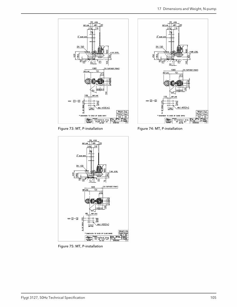
Figure 73: MT, P-installation Figure 74: MT, P-installation
Figure 75: MT, P-installation
17 Dimensions and Weight, N-pump
Flygt 3127, 50Hz Technical Specification 105
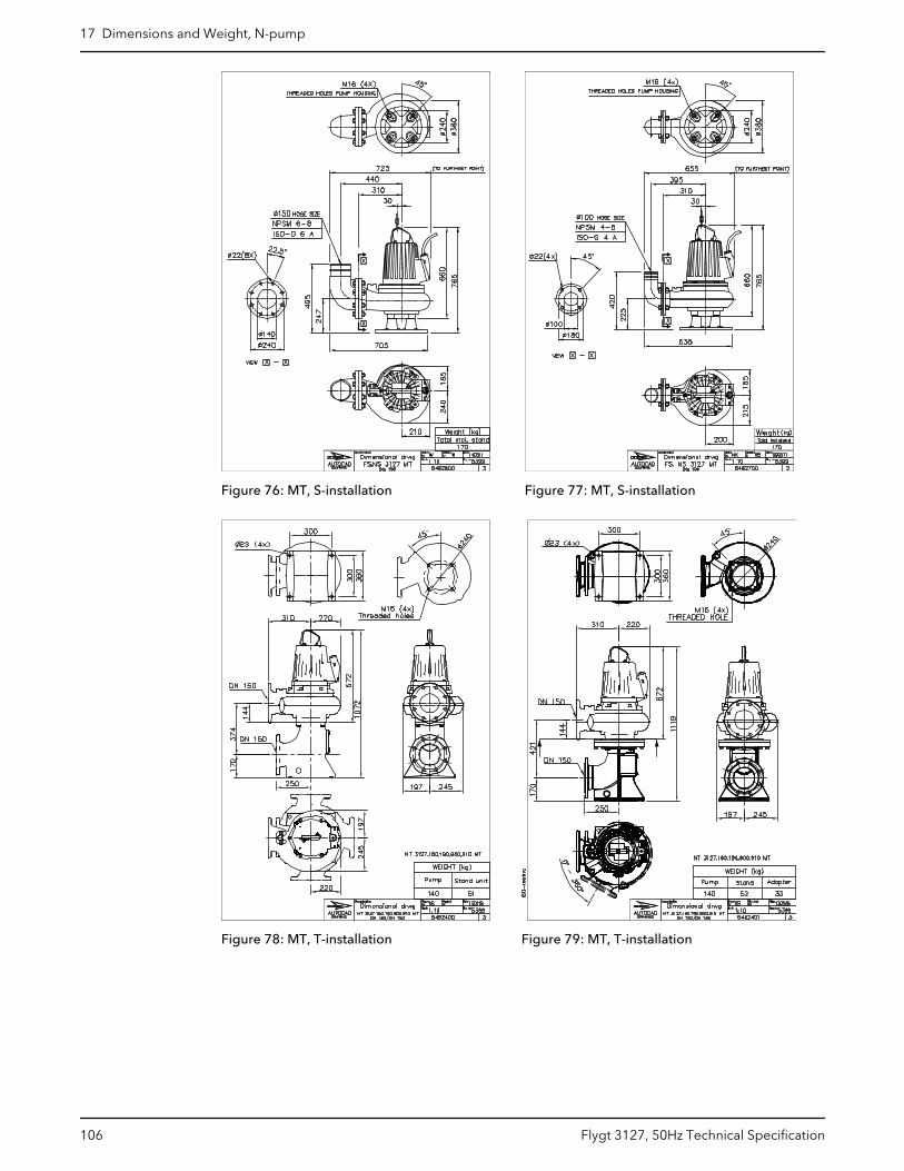
Figure 76: MT, S-installation Figure 77: MT, S-installation
Figure 78: MT, T-installation Figure 79: MT, T-installation
17 Dimensions and Weight, N-pump
106 Flygt 3127, 50Hz Technical Specification
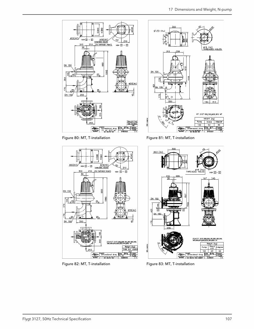
Figure 80: MT, T-installation Figure 81: MT, T-installation
Figure 82: MT, T-installation Figure 83: MT, T-installation
17 Dimensions and Weight, N-pump
Flygt 3127, 50Hz Technical Specification 107
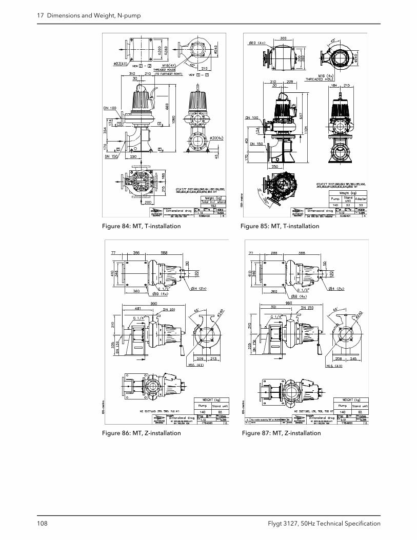
Figure 84: MT, T-installation Figure 85: MT, T-installation
Figure 86: MT, Z-installation Figure 87: MT, Z-installation
17 Dimensions and Weight, N-pump
108 Flygt 3127, 50Hz Technical Specification
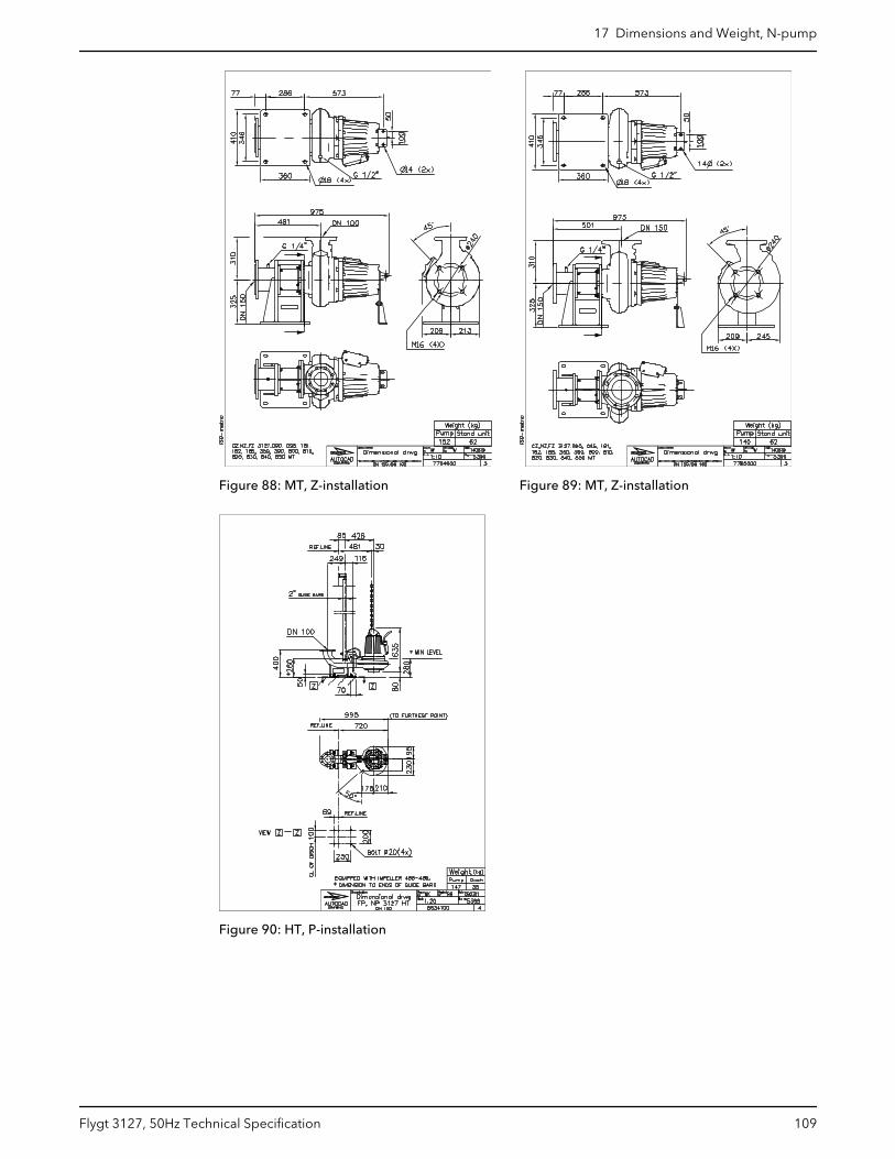
Figure 88: MT, Z-installation Figure 89: MT, Z-installation
Figure 90: HT, P-installation
17 Dimensions and Weight, N-pump
Flygt 3127, 50Hz Technical Specification 109
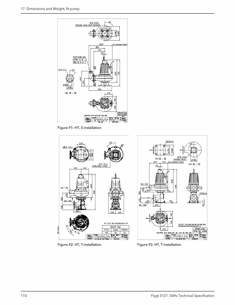
Figure 91: HT, S-installation
Figure 92: HT, T-installation Figure 93: HT, T-installation
17 Dimensions and Weight, N-pump
110 Flygt 3127, 50Hz Technical Specification
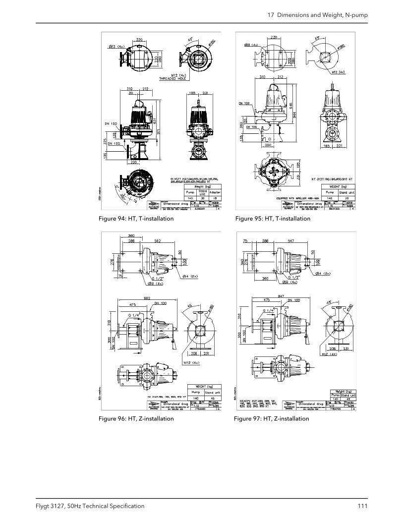
Figure 94: HT, T-installation Figure 95: HT, T-installation
Figure 96: HT, Z-installation Figure 97: HT, Z-installation
17 Dimensions and Weight, N-pump
Flygt 3127, 50Hz Technical Specification 111
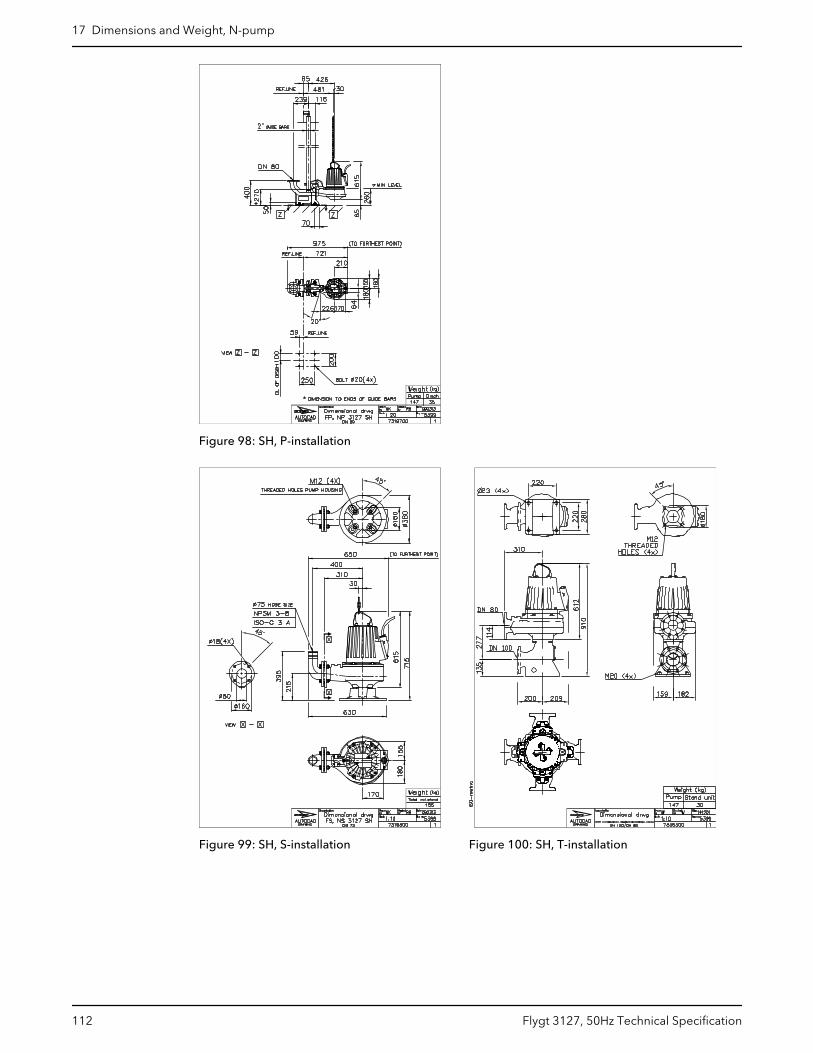
Figure 98: SH, P-installation
Figure 99: SH, S-installation Figure 100: SH, T-installation
17 Dimensions and Weight, N-pump
112 Flygt 3127, 50Hz Technical Specification
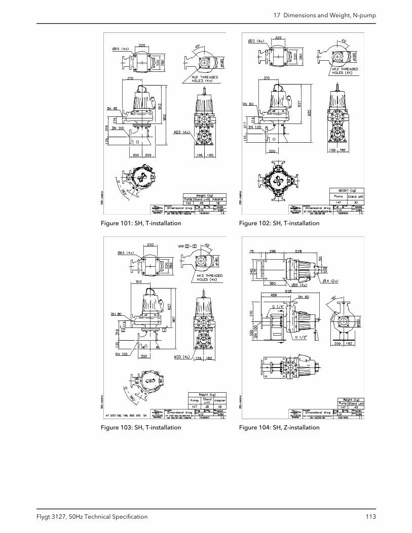
Figure 101: SH, T-installation Figure 102: SH, T-installation
Figure 103: SH, T-installation Figure 104: SH, Z-installation
17 Dimensions and Weight, N-pump
Flygt 3127, 50Hz Technical Specification 113

Figure 105: SH, Z-installation
17 Dimensions and Weight, N-pump
114 Flygt 3127, 50Hz Technical Specification
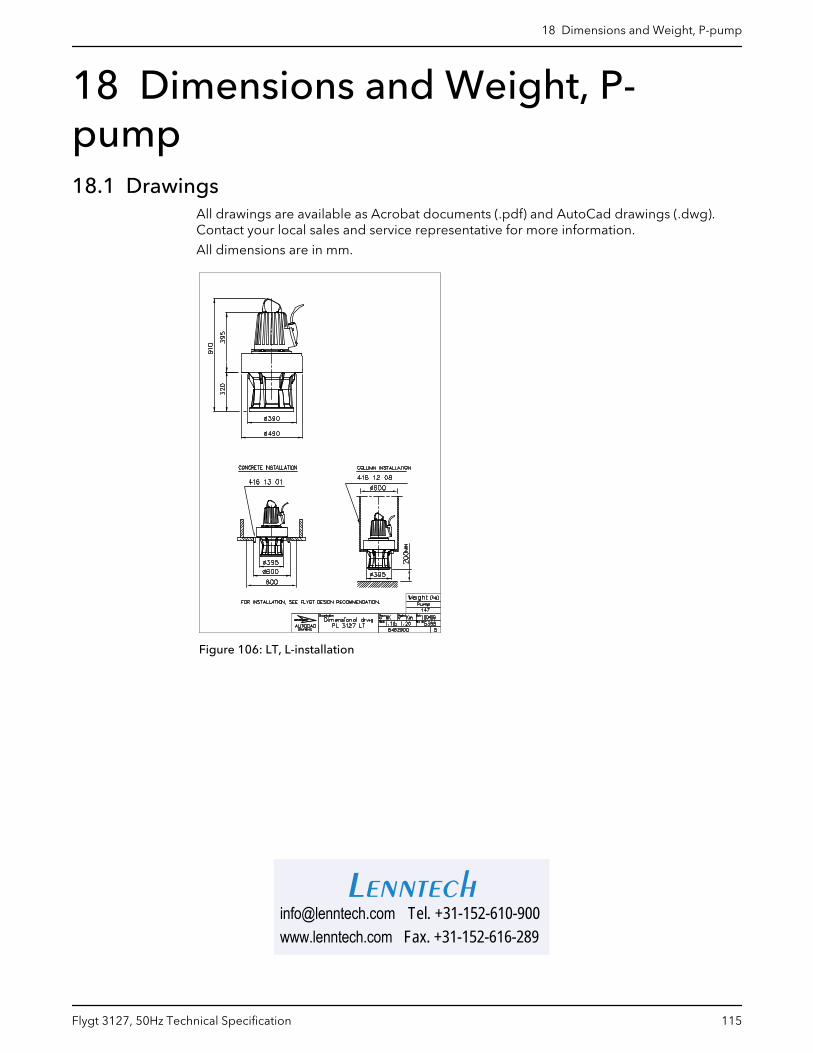
18 Dimensions and Weight, P-pump18.1 Drawings
All drawings are available as Acrobat documents (.pdf) and AutoCad drawings (.dwg).Contact your local sales and service representative for more information.
All dimensions are in mm.
Figure 106: LT, L-installation
18 Dimensions and Weight, P-pump
Flygt 3127, 50Hz Technical Specification 115
[email protected] Tel. +31-152-610-900www.lenntech.com Fax. +31-152-616-289
Lenntech