Embed Size (px)
Citation preview
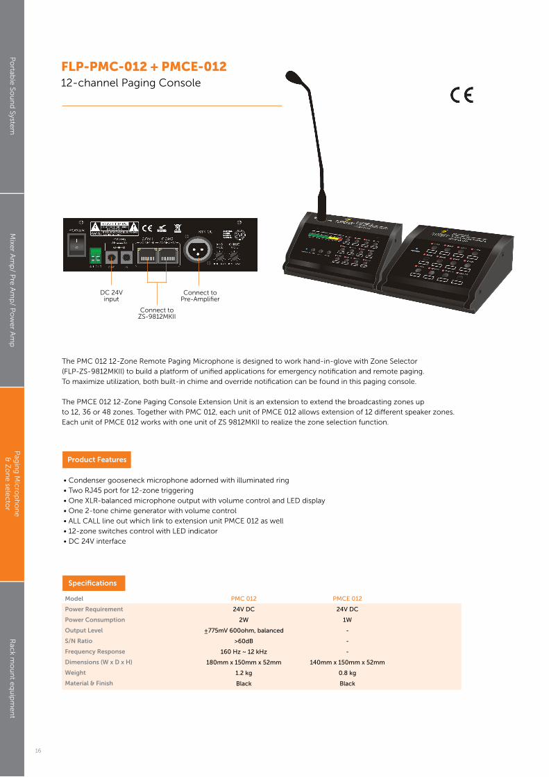
The PMC 012 12-Zone Remote Paging Microphone is designed to work hand-in-glove with Zone Selector
(FLP-ZS-9812MKII) to build a platform of unified applications for emergency notification and remote paging.
To maximize utilization, both built-in chime and override notification can be found in this paging console.
The PMCE 012 12-Zone Paging Console Extension Unit is an extension to extend the broadcasting zones up
to 12, 36 or 48 zones. Together with PMC 012, each unit of PMCE 012 allows extension of 12 different speaker zones.
Each unit of PMCE 012 works with one unit of ZS 9812MKII to realize the zone selection function.
FLP-PMC-012 + PMCE-01212-channel Paging Console
• Condenser gooseneck microphone adorned with illuminated ring
• Two RJ45 port for 12-zone triggering
• One XLR-balanced microphone output with volume control and LED display
• One 2-tone chime generator with volume control
• ALL CALL line out which link to extension unit PMCE 012 as well
• 12-zone switches control with LED indicator
• DC 24V interface
Product Features
Model
Power Requirement
Power Consumption
Output Level
S/N Ratio
Frequency Response
Dimensions (W x D x H)
Weight
Material & Finish
Specifications
PMC 012
24V DC
2W
±775mV 600ohm, balanced
>60dB
160 Hz ~ 12 kHz
180mm x 150mm x 52mm
1.2 kg
Black
PMCE 012
24V DC
1W
-
-
-
140mm x 150mm x 52mm
0.8 kg
Black
Po
rtable
Sou
nd
System
Mixe
r Am
p/ P
re A
mp
/ Po
we
r Am
pP
agin
g M
icro
ph
on
e
& Z
on
e se
lec
tor
Rac
k mo
un
t eq
uip
me
nt
DC 24V input
Connect toPre-Amplifier
Connect toZS-9812MKII
16

Please follow the instructions in this manual to obtain the optimum results from this unit.We also recommend that you keep this manual handy for future reference.
OPERATION MANUAL
TMTM
PROFESSIONAL PUBLIC ADDRESS SYSTEM
12 ZONES PAGING CONSOLE EXTENSION UNIT
FLP-PMCE012
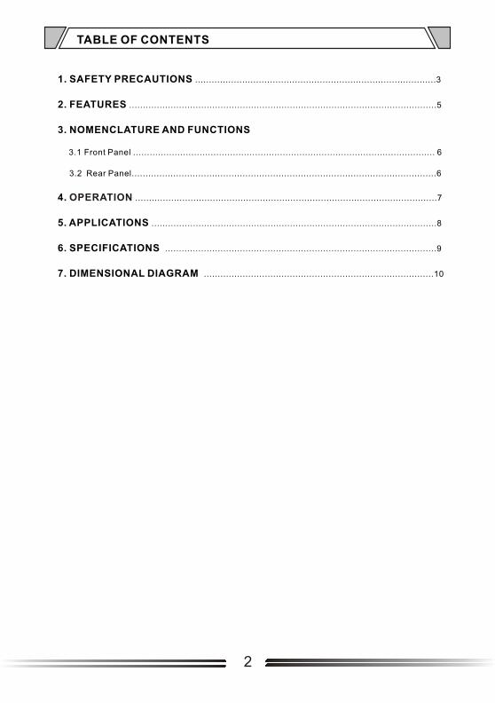
TABLE OF CONTENTS
1. SAFETY PRECAUTIONS .......................................................................................3
2. FEATURES ...............................................................................................................5
3. NOMENCLATURE AND FUNCTIONS
3.1 Front Panel ............................................................................................................. 6
3.2 Rear Panel..............................................................................................................6
4. .............................................................................................................7
5. APPLICATIONS .......................................................................................................8
6. SPECIFICATIONS ..................................................................................................9
7. DIMENSIONAL DIAGRAM ...................................................................................10
OPERATION
2
Be sure to read the instructions in this section carefully before use. Make sure to observe the instructions in this manual as the conventions of safety symbols and messages regarded as very important precautions are included. We also recommend you keep this instruction manual handy for future reference.
Safety Symbol and Message ConventionsSafety symbols and messages described below are used in this manual to prevent bodily injury and property damage which could result from mishandling. Before operating your product, read this manual first and understand the safety symbols and messages so you are thoroughly aware of the potential safety
Indicates a potentially hazardous situation which, if mishandled, couldresult in death or serious personal injury.
Indicates a potentially hazardous situation which, if mishandled, couldresult in moderate or minor personal injury, and/or property damage.
When Installing the Unit
Do not expose the unit to rain or an environment where it may be splashed by water or other liquids, as doing so may result in fire or electric shock.
Use the unit only with the voltage specified on the unit. Using a voltage higher than that which is specified may result in fire or electric shock.
Do not cut, kink, otherwise damage nor modify the power supply cord. In addition, avoid using the power cord in close proximity to heaters, and never place heavy objects -- including the unit itself -- on the power cord, as doing so may result in fire or electric shock.
Be sure to replace the unit's terminal cover after connection completion. Because high voltage is applied to the speaker terminals, never touch these terminals to avoid electric shock.
Be sure to ground to the safety ground (earth) terminal to avoid electric shock. Never ground to a gas pipe as a catastrophic disaster may result.
Avoid installing or mounting the unit in unstable locations, such as on a rickety table or a slanted surface. Doing so may result in the unit falling down, causing personal injury and/or property damage.
When the Unit is in Use
Should the following irregularity be found during use, immediately switch off the power, disconnect the power supply plug from the AC outlet and contact your nearest dealer. Make no further attempt to operate the unit in this condition as this may cause fire or electric shock. If you detect smoke or a strange smell coming from the unit. If water or any metallic object gets into the unit If the unit falls, or the unit case breaks If the power supply cord is damaged (exposure of the core, disconnection, etc.) If it is malfunctioning (no tone sounds.)
To prevent a fire or electric shock, never open nor remove the unit case as there are high voltage components inside the unit. Refer all servicing to your nearest dealer.
Do not place cups, bowls, or other containers of liquid or metallic objects on top of the unit. If they accidentally spill into the unit, this may cause a fire or electric shock.
Do not insert nor drop metallic objects or flammable materials in the ventilation slots of the unit's cover, as this may result in fire or electric shock.
1. SAFETY PRECAUTIONS
3
An all-pole mains switch with a contact separation of at least 3 mm in each pole shall be incorporated inthe electrical installation of the building.
When Installing the Unit
Never plug in nor remove the power supply plug with wet hands, as doing so may cause electric shock.
When unplugging the power supply cord, be sure to grasp the power supply plug; never pull on the cord itself. Operating the unit with a damaged power supply cord may cause a fire or electric shock.
When moving the unit, be sure to remove its power supply cord from the wall outlet. Moving the unit with the power cord connected to the outlet may cause damage to the power cord, resulting in fire or electric shock. When removing the power cord, be sure to hold its plug to pull.
Do not block the ventilation slots in the unit's cover. Doing so may cause heat to build up inside the unit and result in fire.
Avoid installing the unit in humid or dusty locations, in locations exposed to the direct sunlight, near the heaters, or in locations generating sooty smoke or steam as doing otherwise may result in fire or electric shock.
When the Unit is in Use
Do not place heavy objects on the unit as this may cause it to fall or break which may result in personal injury and/or property damage. In addition, the object itself may fall off and cause injury and/or damage.
Make sure that the volume control is set to minimum position before power is switched on. Loud noise produced at high volume when power is switched on can impair hearing.
Do not operate the unit for an extended period of time with the sound distorting. This is an indication of a malfunction, which in turn can cause heat to generate and result in a fire.
Contact your dealer as to the cleaning. If dust is allowed to accumulate in the unit over a long period of time, a fire or damage to the unit may result.
If dust accumulates on the power supply plug or in the wall AC outlet, a fire may result. Clean it periodically. In addition, insert the plug in the wall outlet securely.
Switch off the power, and unplug the power supply plug from the AC outlet for safety purposes when cleaning or leaving the unit unused for 10 days or more. Doing otherwise may cause a fire or electric shock.
SAFETY PRECAUTIONS
4

2. FEATURES
1. With two RJ45 port for 12 zone triggering.
2. 12 zone switches control witr LED indicator.
3. 24V DC main power supply with link out function.
4. ALL CALL line in and out connector to extend the ALL CALL function to another unit.
5
3. NOMENCLATURE AND FUNCTIONS
3.1 FRONT PANEL
1
6
2
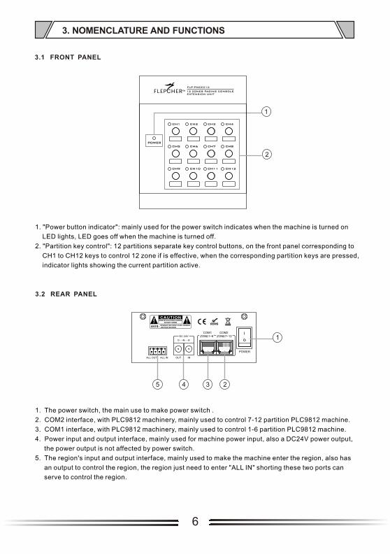
1. "Power button indicator": mainly used for the power switch indicates when the machine is turned on
LED lights, LED goes off when the machine is turned off.
2. "Partition key control": 12 partitions separate key control buttons, on the front panel corresponding to
CH1 to CH12 keys to control 12 zone if is effective, when the corresponding partition keys are pressed,
indicator lights showing the current partition active.
1
2345
1. The power switch, the main use to make power switch .
2. COM2 interface, with PLC9812 machinery, mainly used to control 7-12 partition PLC9812 machine.
3. COM1 interface, with PLC9812 machinery, mainly used to control 1-6 partition PLC9812 machine.
4. Power input and output interface, mainly used for machine power input, also a DC24V power output,
the power output is not affected by power switch.
5. The region's input and output interface, mainly used to make the machine enter the region, also has
an output to control the region, the region just need to enter "ALL IN" shorting these two ports can
serve to control the region.
3.2 REAR PANEL

7
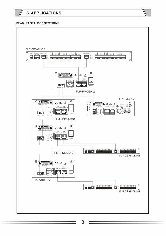
1. The COM1 and COM2 will be connected to the left REMOTE SELECT(Z1~Z6) and right REMOTE
SELECT(Z7~Z12) of the FLP-ZS9812MKII respectively.
2. Network cable using the straight-through cable.
3. When press ALL CALL on FLP-ZS9812MKII, all 12 zones LED of FLP-PMC012 and FLP-PMCE012
should be switch on.
4. When press ALL CALL on FLP-PMC012, also all 12 zones LED of FLP-ZS9812MKII and FLP-PMCE012
should switch on.
5. When press ALL CALL on FLP-ZS9812MKII, which connect to FLP-PMCE012, only corresponding
FLP-PMCE012 12 zones LED are switch on. 12 zones for other FLP-PMC012 and other FLP-PMCE012
and other FLP-ZS9812MKII cannot switch on.
NOTE: the instructions refer to the instructions used in conjunction with FLP-ZS9812MKII.
4. OPERATION
REAR PANEL CONNECTIONS
8
POWER
CHIMEVOL
MICVOL
MIN MAXMIN MAX
COM1 COM2ZONE1~6 ZONE7~12
MIX OUT
ALL OUT OUT IN
RISQUE DE CHOC ELECTRIQUE-NE PAS OUVRIRAVIS:
RISK OF ELECTRIC SHOCKDO NOT OPEN
POWER 24V 2A
DC24V+ -
RELAY TRIG
RELAY CON T
REMOTE SELECT
PIN 1-Z1PIN 2-Z2PIN 3-Z3PIN 4-Z4PIN 5-Z5PIN 6-Z6PIN 7-ACPIN 8-PR
AMP 1
10
0V
CO
M
ZONE 11
00
V
CO
M
AMP 2
10
0V
CO
M
ZONE 2
10
0V
CO
M
AMP 3
10
0V
CO
M
ZONE 3
10
0V
CO
M
AMP 4
10
0V
CO
M
ZONE 4
10
0V
CO
M
AMP 5
10
0V
CO
M
ZONE 5
10
0V
CO
M
AMP 6
10
0V
CO
M
ZONE 6
10
0V
CO
M
AMP 9
10
0V
CO
M
ZONE 9
10
0V
CO
M
AMP10
10
0V
CO
M
ZONE10
10
0V
CO
M
AMP 7
10
0V
CO
M
ZONE 7
10
0V
CO
M
AMP 8
10
0V
CO
M
ZONE 8
10
0V
CO
M
AMP11
10
0V
CO
M
ZONE11
10
0V
CO
M
AMP12
10
0V
CO
M
ZONE12
10
0V
CO
MREMOTE SELECT
PIN 1-Z7PIN 2-Z8PIN 3-Z9PIN 4-Z10PIN 5-Z11PIN 6-Z12PIN 7-ACPIN 8-GND
AMPLIFIER INPUTS-ZONE OUTPUTS FOR ZONE 1 TO 6 AMPLIFIER INPUTS-ZONE OUTPUTS FOR ZONE 7 TO 12
DC24V+ -
RELAY TRIG
RELAY CON T
REMOTE SELECT
PIN 1-Z1PIN 2-Z2PIN 3-Z3PIN 4-Z4PIN 5-Z5PIN 6-Z6PIN 7-ACPIN 8-PR
AMP 1
10
0V
CO
M
ZONE 1
10
0V
CO
M
AMP 2
10
0V
CO
M
ZONE 2
10
0V
CO
M
AMP 3
10
0V
CO
M
ZONE 3
10
0V
CO
M
AMP 4
10
0V
CO
M
ZONE 4
10
0V
CO
M
AMP 5
10
0V
CO
M
ZONE 5
10
0V
CO
M
AMP 6
10
0V
CO
M
ZONE 6
10
0V
CO
M
AMP 9
10
0V
CO
M
ZONE 9
10
0V
CO
M
AMP10
10
0V
CO
M
ZONE10
10
0V
CO
M
AMP 7
10
0V
CO
M
ZONE 7
10
0V
CO
M
AMP 8
10
0V
CO
M
ZONE 8
10
0V
CO
M
AMP11
10
0V
CO
M
ZONE11
10
0V
CO
M
AMP12
10
0V
CO
M
ZONE12
10
0V
CO
MREMOTE SELECT
PIN 1-Z7PIN 2-Z8PIN 3-Z9PIN 4-Z10PIN 5-Z11PIN 6-Z12PIN 7-ACPIN 8-GND
AMPLIFIER INPUTS-ZONE OUTPUTS FOR ZONE 1 TO 6 AMPLIFIER INPUTS-ZONE OUTPUTS FOR ZONE 7 TO 12
5. APPLICATIONS
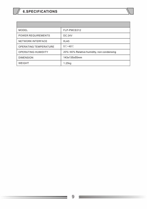
6.SPECIFICATIONS
MODEL
POWER REQUIREMENTS
NETWORK INTERFACE
OPERATING TEMPERATURE
WEIGHT
DIMENSION
OPERATING HUMIDITY
RJ45
5 ~40
20%~80% Relative humidity, non condensing
1.25kg
FLP-PMCE012
143x135x55mm
DC 24V
9
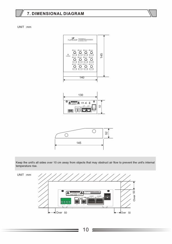
7. DIMENSIONAL DIAGRAM
10

Version 0.1
TMTM