Embed Size (px)
Citation preview

Floppy Disk Storage

ObjectivesIn this chapter, you will:-Understand how magnetic fields are used to store data-Identify and understand the operation of the major components in a floppy drive-Understand floppy cables and connectors-Learn how floppy disks are formatted-Understand the evolution and the eventual extinction of floppy disks-Troubleshoot problems with floppy disk drives

Magnetic StoragePermanent or semipermanent computer data storage works by either optical or magnetic principles or, in some cases, a combination of the two. In the case of magnetic storage, a stream of binary computer data bits (0s and 1s) is stored by magnetizing tiny pieces of metal embedded on the surface of a disk or tape in a pattern that represents the data. Later this magnetic pattern can be read and converted back into the exact same stream of bits you started with.

How Data is StoredAll magnetic storage devices, such as floppy disk drives and hard disk drives, read and write data by using electromagnetism. This basic principle of physics states that as an electric current flows through a conductor (wire), a magnetic field is generated around the conductor.
The magnetic field generated by a wire conductor can exert an influence on magnetic material in the field.
When applied to magnetic storage devices, this two-way operation of electromagnetism makes recording data on a disk and reading that data back later possible.

How Data is StoredThe read/write heads in a magnetic storage device are U-shaped pieces of conductive material, with the ends of the U situated directly above (or next to) the surface of the actual data storage medium.
The disk or tape that constitutes the actual storage medium consists of some form of substrate material (such as Mylar for floppy disks or aluminum or glass for hard disks) on which a layer of magnetizable material has been deposited. This material usually is a form of iron oxide with various other elements added.

How Data is StoredWhen the magnetic field passes through the medium, the particles in the area below the head gap are aligned in the same direction as the field emanating from the gap.
The term flux describes a magnetic field that has a specific direction or polarity. As the surface of the medium moves under the drive head, the head can generate what is called a magnetic flux of a given polarity over a specific region of the medium. When the flow of electric current through the coils in the head is reversed, so is the magnetic field polarity or flux in the head gap.

How Data is StoredAs you can see storage devices read and write data by means of basic electromagnetic principles. A drive writes data by passing electrical currents through an electromagnet (the drive head), generating a magnetic field that is stored on the medium.
The drive reads data by passing the head back over the surface of the medium. As the head encounters changes in the stored magnetic field, it generates a weak electrical current that indicates the presence or absence of flux transitions in the signal as it was originally written.

Floppy Disk StorageThe overall data capacity of a disk is determined by the type of floppy.
The density of a disk refers to how closely the computer can pack the data on it.
High and extra high density disks are made of higher quality materials that can hold the magnetic charge better.

Floppy Disks/DriveThe floppy drive is the most simple and universal of the drive types.
-Originally, floppy disks were actually just that – floppy. The casing for the disk was thin plastic and was rather flexible.
-The most popular “floppies” of today are the 3.5” disk, encased in a stiff plastic case with a metal shield to protect the internal magnetic media disk.

Floppy Drive Components
The drive is made up of several basic components:

A floppy disk drive normally has two read/write heads, one for each side of the disk, with both heads being used for reading and writing on their respective disk sides
The heads themselves are made of soft ferrous (iron) compounds with electromagnetic coils. Each head is a composite design, with a read/write head centered within two tunnel-erase heads in the same physical assembly
Floppy Drive Components (R-W Heads)

Floppy disk drives use a recording method called tunnel erasure. As the drive writes to a track, the trailing tunnel-erase heads erase the outer bands of the track, trimming it cleanly on the disk. The heads force the data into a specified narrow "tunnel" on each track. This process prevents the signal from one track from being confused with the signals from adjacent tracks
Floppy Drive Components (R-W Heads)

Floppy Drive Components (R-W Heads)
The floppy disk drive's two heads are spring-loaded and physically grip the disk with a small amount of pressure, which means they are in direct contact with the disk surface while reading and writing to the disk. Because floppy disk drives spin at only 300rpm or 360rpm, this pressure does not present an excessive friction problem.

Floppy Drive Components (Head Actuator)
The head actuator for a floppy disk drive is what moves the heads across the disk and is driven by a special kind of motor, called a stepper motor

Floppy Drive Components (Spindle Motor)
The spindle motor is what spins the disk. The normal speed of rotation is either 300rpm or 360rpm, depending on the type of drive.
Floppy Drive Components (Circuit Boards)
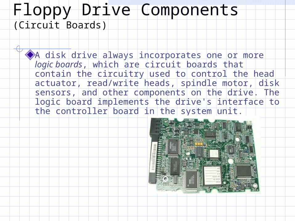
A disk drive always incorporates one or more logic boards, which are circuit boards that contain the circuitry used to control the head actuator, read/write heads, spindle motor, disk sensors, and other components on the drive. The logic board implements the drive's interface to the controller board in the system unit.

Floppy Drive Components (Controller)
Today's PCs have the floppy controller integrated into the motherboard, usually in the form of a Super I/O chip that also includes the serial and parallel interfaces, among other things.Even though the floppy controller can be found in the Super I/O chip on the motherboard, it is still interfaced to the system via the ISA bus and functions exactly as if it were a card installed in an ISA slot. These built-in controllers are normally configured via the system BIOS Setup routines and can be disabled if an actual floppy controller card is going to be installed.Whether it is built in or not, all primary floppy controllers use a standard set of system resources:
-IRQ 6 (Interrupt Request)-DMA 2 (Direct Memory Address)-I/O ports 3F0-3F5, 3F7 (input/output)

Floppy Drive Components (Connectors)
The drive has a standard four pin inline power connection to receive power from the power supply.
-Typically, 5 ¼” drives use the large style power connector, whereas most 3 ½” drives use the smaller version

Floppy Drive Components (Drive Cable)
It has a 34 pin ribbon cable that connects to the CPU data bus. The cable has a drive select twist between the end plug (A:) and the second plug (B:). If you install only a single floppy disk drive, you use the connector after the twist, which causes the drive to be recognized as drive A.
Floppy Ribbon Cable
Drive Select Twist Motherboard Bus
Connector

Disk Operation
The physical operation of a disk drive is fairly simple to describe. The disk rotates in the drive at either 300rpm or 360rpm. Most drives spin at 300rpm; only the 5 1/4-inch 1.2MB drives spin at 360rpm. With the disk spinning, the heads can move in and out approximately one inch and write 80 tracks. The tracks are written on both sides of the disk and are therefore sometimes called cylinders.A single cylinder comprises the tracks on the top and bottom of the disk. The heads record by using a tunnel-erase procedure that writes a track to a specified width, and then erases the edges of the track to prevent interference with any adjacent tracks.

Disk Changing
The standard PC floppy controller and drive use a special signal on pin 34 called Disk Change to determine whether the disk has been changed or more accurately, to determine whether the same disk loaded during the previous disk access is still in the drive. Disk Change is a pulsed signal that changes a status register in the controller to let the system know that a disk has been either inserted or ejected. This register is set to indicate that a disk has been inserted or removed (changed) by default.

Types of Floppy Drives (1.44MB)
The 3 1/2-inch, 1.44MB, high-density (HD) drives first appeared from IBM in the PS/2 product line introduced in 1987. This type of floppy drive is still the most popular in systems today.The drive records 80 cylinders consisting of 2 tracks each with 18 sectors per track, resulting in a formatted capacity of 1.44MB. Some disk manufacturers label these disks as 2.0MB, and the difference between this unformatted capacity and the formatted usable result is lost during the format.Note that the 1,440KB of total formatted capacity does not account for the areas the FAT file system reserves for file management, leaving only 1,423.5KB of actual file-storage area.

Types of Floppy Drives (2.88MB)
The 3 1/2-inch, 2.88MB drive was developed by Toshiba Corporation in the 1980s and was officially announced in 1987. Toshiba began production manufacturing of the drives and disks in 1989, and several vendors began selling the drives as upgrades for their systems. Due to high media costs and a relatively low increase in data capacity, these drives never caught on widely, although virtually all systems today have built-in support for them. The 2.88MB extra high-density (ED) drive uses a technique called vertical recording to achieve its great linear density of 36 sectors per track. This technique increases density by magnetizing the domains perpendicular to the recording surface. By essentially placing the magnetic domains on their ends and stacking them side by side, the disk density increases enormously.