Embed Size (px)
Citation preview
USB Disk Emulator
User Guide
ipcas GmbH Gundstraße 15 D-91056 Erlangen Telefon: +49 (0)9131/ 7677-0 Telefax: +49 (0)9131/ 7677-78 Internet: http://www.ipcas.de E-Mail: [email protected]
Subject to change without prior notice Date: 04-04-11
ipcas GmbH USB-Disk Emulator v3.0 Seite 2 von 15
Contens Page
1. INTRODUCTION...................................................................3
Legal Information................................................................................................3
Safety Reverences .............................................................................................3
Registered Trademarks ......................................................................................4
Important Information .........................................................................................4
Non-warranty......................................................................................................4
Limited Warranty ................................................................................................4
2. DEVICE DESCRIPTION .......................................................5
3. INTERFACE DESCRIPTION ................................................6
3.1 Front-side USB Disk Emulator......................................................................6
3.2 Back-side USB Disk Emulator ......................................................................7
3.3 Floppy Controller Interface ...........................................................................8
4. INSTALLATION.....................................................................9
4.1 Start Up ........................................................................................................9
4.2 Creating a Formatted Image.......................................................................12
4.3 Creating a Template Image ........................................................................12
4.3 Accessing Files in a FAT12 Formatted Image (feitool) ...............................13
5. SPECIFICATIONS USB FLOPPY EMULATOR..................15
Subject to change without prior notice Date: 04-04-11
ipcas GmbH USB-Disk Emulator v3.0 Seite 3 von 15
1. Introduction
Legal Information COPYRIGHT © 2011 ipcas GmbH All rights reserved. No part of this document may be copied out, copied, reproduced, or transferred in other form without the previous express written approval of the ipcas GmbH. Misprint, mistakes and changes are left. In so far as legally as possible, we cannot accept any liability for consequential damage caused by using this guide. In other respects we shall accept liability for intention and gross negligence only. We have done our utmost to ensure that the information in this user guide is complete, accurate and up to date. We don’t give any warranty for the correctness of the made details or for the applicability of the described Product for any special purpose. We cannot provide any warranty that changes to third-party equipment, which is referred to in this guide, will have no effect on the applicability of the information provided here. The author reserves all rights, including the right to reproduce this guide in full or part in any form. The content is subject to change without prior notification. The product is subject to technical change without prior notification.
Safety Reverences As is the case with all electrical equipment, there are some basic safety precautions that you should apply. These safety precautions are primarily for your safety but also to prevent damage to the device. Settings not described in this guide and changes to the device electronics are to be carried out by an authorized vendor only. Read the user guide carefully and keep it to hand. Make sure that the device is placed on a stable and flat surface. Make also sure that for rail-mounted devices the top hat rail is sufficiently grounded and the rail spring has good contact. Use the device at a tempered, dust- and vibration free place. Excessive heat will damage the device. Therefore it should not suspend to high temperatures (No mounting near heat sources. No direct sunlight.). Device shouldn’t be used at exceptional humidity. Make sure no liquids or particles can get into the device. Don’t place the device near to magnetic fields because this can be responsible for data loss. (Never make any changes to the device that is not described in the user guide.) It’s forbidden to run the device with another supply voltage which isn’t described for the device. This could damage the device and you will have to pay for the repairs. Only the authorized vendor may change the input voltage if this should become necessary. The power supply must be free from overloads and other malfunction. The interfaces must be free from overloads, different potential and other malfunction. Otherwise the device could become damaged. Don’t carry out any modifications in the device which are not described in this user guide. That could damage the device and the owner will be liable to pay the costs. Make sure that the following conditions are fulfilled: Use a suitable power supply unit. In case of any doubt, consult your supplier. The device should be used exclusively with the mains unit supplied. Using a different power supply unit may lead to the device being damaged. If the device is damaged, disconnect it from the mains. Arrange for immediate repair. Make sure that the mains socket is located near to the device and is easily accessible. You have to pull the mains plug completely to disconnect. In case of using an extension cable or multiple contact plug, the maximum power rating must not be exceeded. The mains cable must be protected against damage by yourself. Do not place anything on the cable and place it on a safe ground so that there is no danger of stepping on or tripping over it. A damaged mains cable must be replaced immediately. Make sure that the mains cable is disconnected before starting to clean the device. Use a dry cloth only. Do not use any liquid or aerosol cleaning agent.
Registered Trademarks All used Trademarks in this Document are stated for identification purposes and may be the property of the various holders.
Important Information Please, pay attention to electrostatic unloadings. Use a suitable work station for the work with CMOS components. Before you consult the customer service of your supplier, you should notice the notes in this manual. Even during the warranty period, costs may arise by utilising the customer service if the concerned fault or problem can be corrected from the customer himself on the basis of this guide describing the solution or remedy.To clean the device just use dry cloth. Don’t use liquid or aerosol cleaner. Removing the serial number will void the warranty rights. Damage caused by inappropriate packing will not be borne by the forwarding agent / insurance company.
Non-warranty The ipcas GmbH is not liable for the use of Software or Products which are mentioned in this document. Also this company is not liable if use of these products hurt any existing or future licence or patent laws from third party. ipcas GmbH reserves the right to execute modifications of the contents without previous announcements.
Limited Warranty The ipcas GmbH guarantees the final consumer (purchaser) in the case of appropriate use that the device will be for a period of 24 months without any material damage and free of caused labour costs. In case of production errors or damaged material, the ipcas GmbH will do anything to restore the normal operating status (i.e. repair or exchange parts or the whole product), within the warranty period and if the receipt is available. In free discretion of the ipcas GmbH, the exchange may contain new or as good as new devices or parts which have the same functionality like the original device. This warranty will expire instantly if the device is modified, used incorrect or sportive/careless damaged. This also takes effect if the product is affected through force majeure or by using the device out the proper working conditions. Only the purchaser has claim for repair or exchange. Other pretensions do not exist. These warranty conditions substitute all other warranties or warranty services, no matter if assertive, explicit or implicit. They don't mean that the product came out for certain or economic intention or any other intention. Not at all and in no way the ipcas GmbH is liable for indirect or any damage or consequential damage which the customer eventually suffers. The ipcas GmbH doesn’t give any warranty that the software / hardware match your requirements or work accurately and faultless. With the installation of the software / hardware you take not only the full responsibility for the use of the software / hardware but also for the expected results, the installation, the application and the achieved results which were made by the use of the software. For claiming your warranty service, please approach your Vendor, who will send back the device to the ipcas GmbH. If there's no receipt together with the device or if the whole thing isn’t under the warranty period anymore, ipcas will repair or change the damaged parts (own choice) and charge the parts and the working time. Repaired or replacement devices will be sent back to the added address. CAUTION: Product warranty will be void if the serial number is removed. Through unsuitable packing caused damage wouldn’t be overtaken by the carrier / insurer.
Subject to change without prior notice Date: 04-04-11
ipcas GmbH USB-Disk Emulator v3.0 Seite 4 von 15
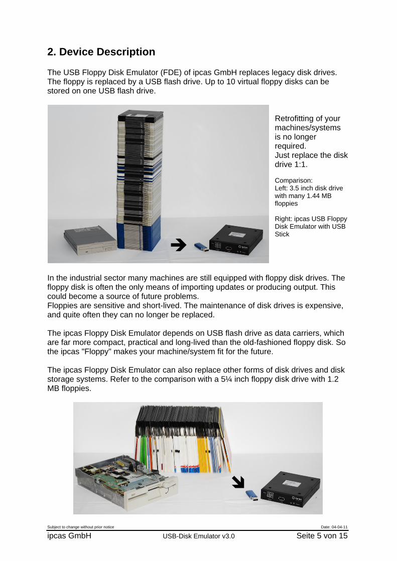
2. Device Description The USB Floppy Disk Emulator (FDE) of ipcas GmbH replaces legacy disk drives. The floppy is replaced by a USB flash drive. Up to 10 virtual floppy disks can be stored on one USB flash drive.
Retrofitting of your machines/systems is no longer required. Just replace the disk drive 1:1. Comparison: Left: 3.5 inch disk drive with many 1.44 MB floppies Right: ipcas USB Floppy Disk Emulator with USB Stick
In the industrial sector many machines are still equipped with floppy disk drives. The floppy disk is often the only means of importing updates or producing output. This could become a source of future problems. Floppies are sensitive and short-lived. The maintenance of disk drives is expensive, and quite often they can no longer be replaced. The ipcas Floppy Disk Emulator depends on USB flash drive as data carriers, which are far more compact, practical and long-lived than the old-fashioned floppy disk. So the ipcas "Floppy" makes your machine/system fit for the future. The ipcas Floppy Disk Emulator can also replace other forms of disk drives and disk storage systems. Refer to the comparison with a 5¼ inch floppy disk drive with 1.2 MB floppies.
Subject to change without prior notice Date: 04-04-11
ipcas GmbH USB-Disk Emulator v3.0 Seite 5 von 15
3. Interface description
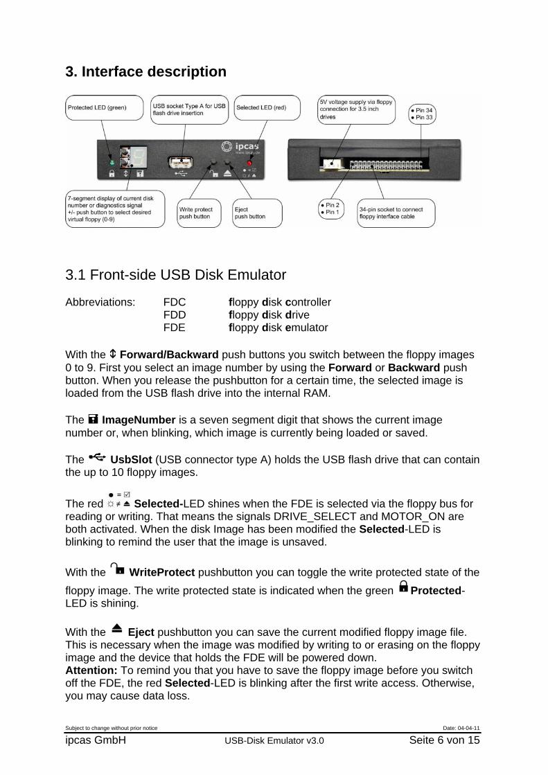
3.1 Front-side USB Disk Emulator Abbreviations: FDC floppy disk controller
FDD floppy disk drive FDE floppy disk emulator
With the Forward/Backward push buttons you switch between the floppy images 0 to 9. First you select an image number by using the Forward or Backward push button. When you release the pushbutton for a certain time, the selected image is loaded from the USB flash drive into the internal RAM. The ImageNumber is a seven segment digit that shows the current image number or, when blinking, which image is currently being loaded or saved. The UsbSlot (USB connector type A) holds the USB flash drive that can contain the up to 10 floppy images.
The red Selected-LED shines when the FDE is selected via the floppy bus for reading or writing. That means the signals DRIVE_SELECT and MOTOR_ON are both activated. When the disk Image has been modified the Selected-LED is blinking to remind the user that the image is unsaved. With the WriteProtect pushbutton you can toggle the write protected state of the floppy image. The write protected state is indicated when the green Protected-LED is shining. With the Eject pushbutton you can save the current modified floppy image file. This is necessary when the image was modified by writing to or erasing on the floppy image and the device that holds the FDE will be powered down. Attention: To remind you that you have to save the floppy image before you switch off the FDE, the red Selected-LED is blinking after the first write access. Otherwise, you may cause data loss. Subject to change without prior notice Date: 04-04-11
ipcas GmbH USB-Disk Emulator v3.0 Seite 6 von 15
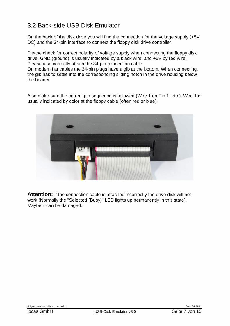
3.2 Back-side USB Disk Emulator On the back of the disk drive you will find the connection for the voltage supply (+5V DC) and the 34-pin interface to connect the floppy disk drive controller. Please check for correct polarity of voltage supply when connecting the floppy disk drive. GND (ground) is usually indicated by a black wire, and +5V by red wire. Please also correctly attach the 34-pin connection cable. On modern flat cables the 34-pin plugs have a gib at the bottom. When connecting, the gib has to settle into the corresponding sliding notch in the drive housing below the header. Also make sure the correct pin sequence is followed (Wire 1 on Pin 1, etc.). Wire 1 is usually indicated by color at the floppy cable (often red or blue).
Attention: If the connection cable is attached incorrectly the drive disk will not work (Normally the "Selected (Busy)" LED lights up permanently in this state). Maybe it can be damaged.
Subject to change without prior notice Date: 04-04-11
ipcas GmbH USB-Disk Emulator v3.0 Seite 7 von 15
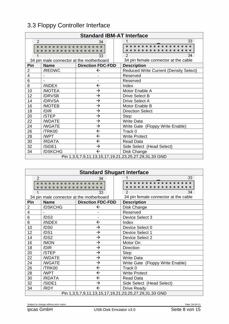
3.3 Floppy Controller Interface
Standard IBM-AT Interface
34 pin male connector at the motherboard
34 pin female connector at the cable
Pin Name Direction FDC-FDD Description 2 /REDWC Reduced Write Current (Density Select) 4 - - Reserved 6 - - Reserved 8 /INDEX Index 10 /MOTEA Motor Enable A 12 /DRVSB Drive Select B 14 /DRVSA Drive Select A 16 /MOTEB Motor Enable B 18 /DIR Direction Select 20 /STEP Step 22 /WDATE Write Data 24 /WGATE Write Gate (Floppy Write Enable) 26 /TRK00 Track 0 28 /WPT Write Protect 30 /RDATA Read Data 32 /SIDE1 Side Select (Head Select) 34 /DSKCHG Disk Change
Pin 1,3,5,7,9,11,13,15,17,19,21,23,25,27,29,31,33 GND
Standard Shugart Interface
34 pin male connector at the motherboard
34 pin female connector at the cable
Pin Name Direction FDC-FDD Description 2 /DSKCHG Disk Change 4 - - Reserved 6 /DS3 - Device Select 3 8 /INDEX Index 10 /DS0 Device Select 0 12 /DS1 Device Select 1 14 /DS2 Device Select 2 16 /MON Motor On 18 /DIR Direction 20 /STEP Step 22 /WDATE Write Data 24 /WGATE Write Gate (Floppy Write Enable) 26 /TRK00 Track 0 28 /WPT Write Protect 30 /RDATA Read Data 32 /SIDE1 Side Select (Head Select) 34 /RDY Drive Ready
Pin 1,3,5,7,9,11,13,15,17,19,21,23,25,27,29,31,33 GND
Subject to change without prior notice Date: 04-04-11
ipcas GmbH USB-Disk Emulator v3.0 Seite 8 von 15
Subject to change without prior notice Date: 04-04-11
ipcas GmbH USB-Disk Emulator v3.0 Seite 9 von 15
4. Installation
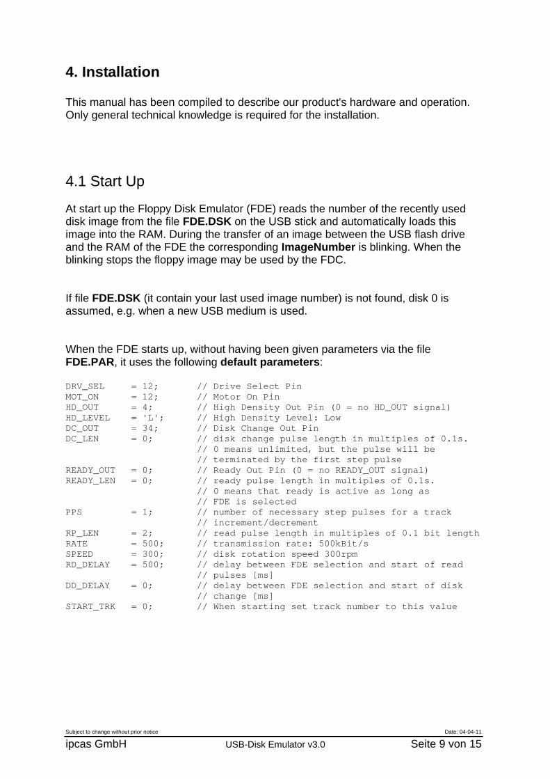
This manual has been compiled to describe our product's hardware and operation. Only general technical knowledge is required for the installation. 4.1 Start Up At start up the Floppy Disk Emulator (FDE) reads the number of the recently used disk image from the file FDE.DSK on the USB stick and automatically loads this image into the RAM. During the transfer of an image between the USB flash drive and the RAM of the FDE the corresponding ImageNumber is blinking. When the blinking stops the floppy image may be used by the FDC. If file FDE.DSK (it contain your last used image number) is not found, disk 0 is assumed, e.g. when a new USB medium is used. When the FDE starts up, without having been given parameters via the file FDE.PAR, it uses the following default parameters: DRV_SEL = 12; // Drive Select Pin MOT_ON = 12; // Motor On Pin HD_OUT = 4; // High Density Out Pin (0 = no HD_OUT signal) HD_LEVEL = 'L'; // High Density Level: Low DC_OUT = 34; // Disk Change Out Pin DC_LEN = 0; // disk change pulse length in multiples of 0.1s.
// 0 means unlimited, but the pulse will be // terminated by the first step pulse
READY_OUT = 0; // Ready Out Pin (0 = no READY_OUT signal) READY_LEN = 0; // ready pulse length in multiples of 0.1s.
// 0 means that ready is active as long as // FDE is selected
PPS = 1; // number of necessary step pulses for a track // increment/decrement
RP_LEN = 2; // read pulse length in multiples of 0.1 bit length RATE = 500; // transmission rate: 500kBit/s SPEED = 300; // disk rotation speed 300rpm RD_DELAY = 500; // delay between FDE selection and start of read
// pulses [ms] DD_DELAY = 0; // delay between FDE selection and start of disk
// change [ms] START_TRK = 0; // When starting set track number to this value
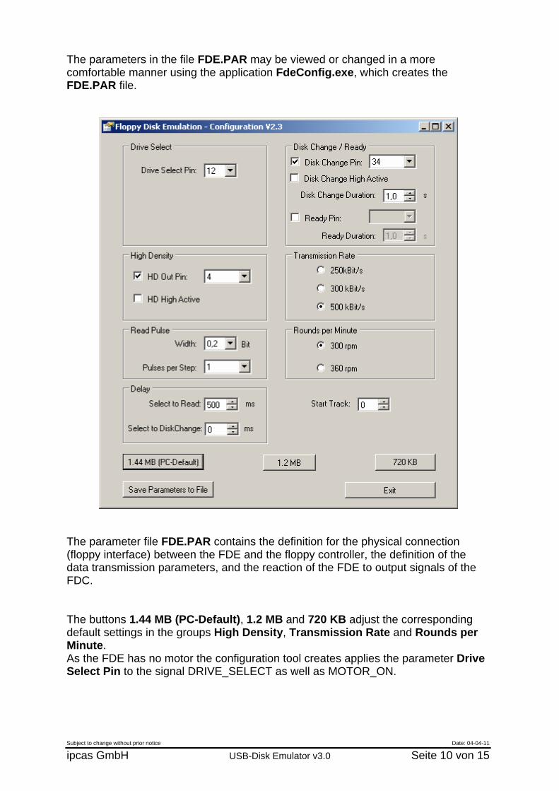
The parameters in the file FDE.PAR may be viewed or changed in a more comfortable manner using the application FdeConfig.exe, which creates the FDE.PAR file.
The parameter file FDE.PAR contains the definition for the physical connection (floppy interface) between the FDE and the floppy controller, the definition of the data transmission parameters, and the reaction of the FDE to output signals of the FDC. The buttons 1.44 MB (PC-Default), 1.2 MB and 720 KB adjust the corresponding default settings in the groups High Density, Transmission Rate and Rounds per Minute. As the FDE has no motor the configuration tool creates applies the parameter Drive Select Pin to the signal DRIVE_SELECT as well as MOTOR_ON.
Subject to change without prior notice Date: 04-04-11
ipcas GmbH USB-Disk Emulator v3.0 Seite 10 von 15
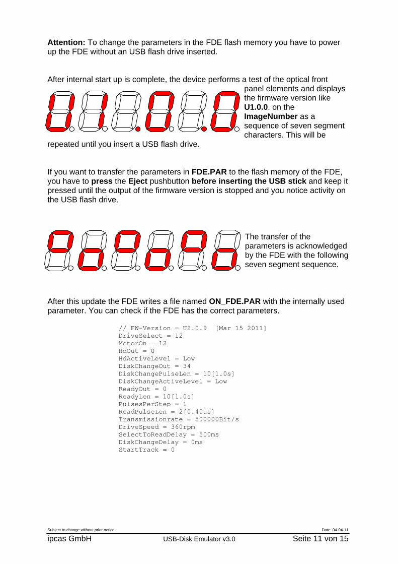
Attention: To change the parameters in the FDE flash memory you have to power up the FDE without an USB flash drive inserted. After internal start up is complete, the device performs a test of the optical front
panel elements and displays the firmware version like U1.0.0. on the ImageNumber as a sequence of seven segment characters. This will be
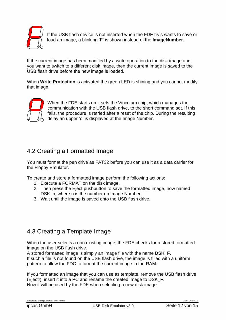
repeated until you insert a USB flash drive. If you want to transfer the parameters in FDE.PAR to the flash memory of the FDE, you have to press the Eject pushbutton before inserting the USB stick and keep it pressed until the output of the firmware version is stopped and you notice activity on the USB flash drive.
The transfer of the parameters is acknowledged by the FDE with the following seven segment sequence.
After this update the FDE writes a file named ON_FDE.PAR with the internally used parameter. You can check if the FDE has the correct parameters.
// FW-Version = U2.0.9 [Mar 15 2011] DriveSelect = 12 MotorOn = 12 HdOut = 0 HdActiveLevel = Low DiskChangeOut = 34 DiskChangePulseLen = 10[1.0s] DiskChangeActiveLevel = Low ReadyOut = 0 ReadyLen = 10[1.0s] PulsesPerStep = 1 ReadPulseLen = 2[0.40us] Transmissionrate = 500000Bit/s DriveSpeed = 360rpm SelectToReadDelay = 500ms DiskChangeDelay = 0ms StartTrack = 0
Subject to change without prior notice Date: 04-04-11
ipcas GmbH USB-Disk Emulator v3.0 Seite 11 von 15
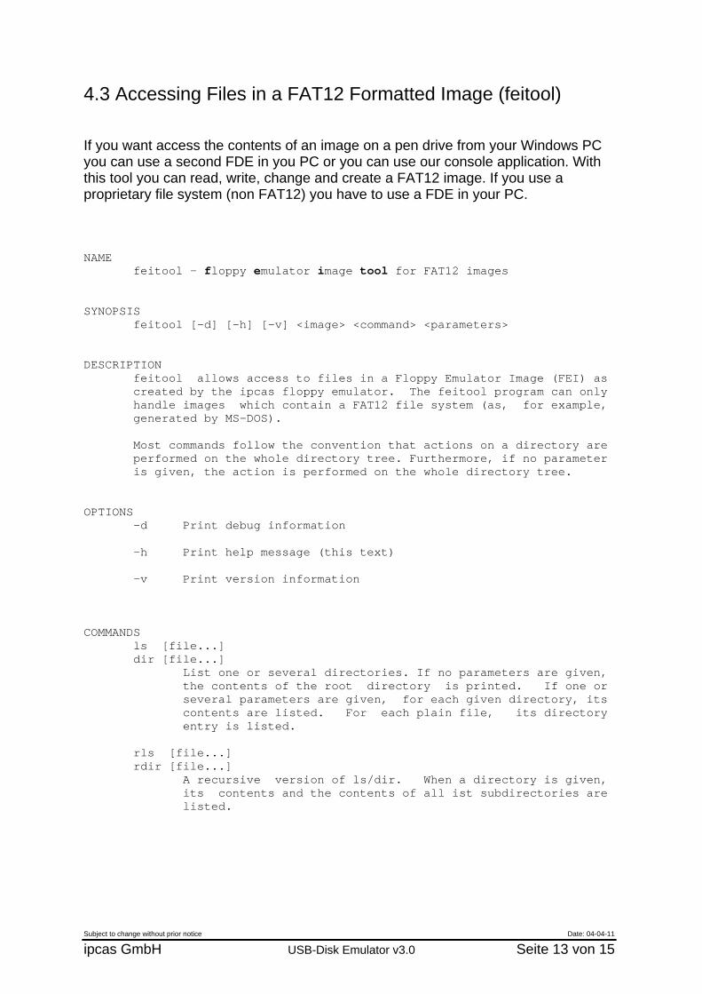
If the USB flash device is not inserted when the FDE try’s wants to save or load an image, a blinking ‘F’ is shown instead of the ImageNumber.
If the current image has been modified by a write operation to the disk image and you want to switch to a different disk image, then the current image is saved to the USB flash drive before the new image is loaded. When Write Protection is activated the green LED is shining and you cannot modify that image.
When the FDE starts up it sets the Vinculum chip, which manages the communication with the USB flash drive, to the short command set. If this fails, the procedure is retried after a reset of the chip. During the resulting delay an upper ‘o’ is displayed at the Image Number.
4.2 Creating a Formatted Image You must format the pen drive as FAT32 before you can use it as a data carrier for the Floppy Emulator. To create and store a formatted image perform the following actions:
1. Execute a FORMAT on the disk image. 2. Then press the Eject pushbutton to save the formatted image, now named
DSK_n, where n is the number on Image Number. 3. Wait until the image is saved onto the USB flash drive.
4.3 Creating a Template Image When the user selects a non existing image, the FDE checks for a stored formatted image on the USB flash drive. A stored formatted image is simply an image file with the name DSK_F. If such a file is not found on the USB flash drive, the image is filled with a uniform pattern to allow the FDC to format the current image in the RAM. If you formatted an image that you can use as template, remove the USB flash drive (Eject!), insert it into a PC and rename the created image to DSK_F. Now it will be used by the FDE when selecting a new disk image.
Subject to change without prior notice Date: 04-04-11
ipcas GmbH USB-Disk Emulator v3.0 Seite 12 von 15
Subject to change without prior notice Date: 04-04-11
ipcas GmbH USB-Disk Emulator v3.0 Seite 13 von 15
4.3 Accessing Files in a FAT12 Formatted Image (feitool) If you want access the contents of an image on a pen drive from your Windows PC you can use a second FDE in you PC or you can use our console application. With this tool you can read, write, change and create a FAT12 image. If you use a proprietary file system (non FAT12) you have to use a FDE in your PC. NAME feitool - floppy emulator image tool for FAT12 images SYNOPSIS feitool [-d] [-h] [-v] <image> <command> <parameters> DESCRIPTION feitool allows access to files in a Floppy Emulator Image (FEI) as created by the ipcas floppy emulator. The feitool program can only handle images which contain a FAT12 file system (as, for example, generated by MS-DOS). Most commands follow the convention that actions on a directory are performed on the whole directory tree. Furthermore, if no parameter is given, the action is performed on the whole directory tree. OPTIONS -d Print debug information -h Print help message (this text) -v Print version information COMMANDS ls [file...] dir [file...] List one or several directories. If no parameters are given, the contents of the root directory is printed. If one or several parameters are given, for each given directory, its contents are listed. For each plain file, its directory entry is listed. rls [file...] rdir [file...] A recursive version of ls/dir. When a directory is given, its contents and the contents of all ist subdirectories are listed.

Subject to change without prior notice Date: 04-04-11
ipcas GmbH USB-Disk Emulator v3.0 Seite 14 von 15
get [file...] Copy files from the FEI file to the host file system. All files will be written to the current working directory or a subdirectory (subsubdirectory ...) thereof. For each plain file given as parameter, the file is copied to the host file system. For each directory, the directory and all its subdirectories are copied recursively. If a file or directory is to be created in a directory that does not exist in the host file system, it is created. If no parameter is given, all files and directories from the FEI file are copied. put [file...] Copy files from the host file system to the FEI file. If a relative path is given, the path is taken to be relative to the FEI's root directory. (That is, if dir1/dir2/file.txt is given on the command line, dir1/dir2/file.txt will be read from the current working directory in the host file system but created in the FEI's root directory.) If an absolute path is given, this path is used both for the host file system and the FEI. For each plain file given as parameter, the file is copied to the FEI file. For each directory, the directory and all its subdirectories are copied recursively. If no parameter is given, all files and directories from the current working directory are FEI file are copied. rm file [file...] del file [file...] Remove plain files from the FEI file. rmdir dir [dir...] rd dir [dir...] Remove directories from the FEI file. The directories must be empty. It is not possible to remove the root directory. rrmdir dir [dir...] rrd dir [dir...] deltree dir [dir...] Remove directories recursively. The directories with all their contents are removed. (It is also possible to put plain files in the command line, which are also removed.) If / or \ is given, all files from the FEI file are removed. (The root directory itself is not removed.) qformat Run a quick format on the FEI, i.e. the root directory and the FATs are reinititalised.
5. Specifications USB Floppy Emulator
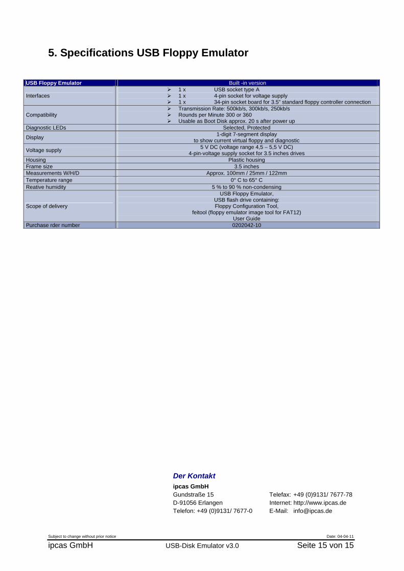
USB Floppy Emulator Built -in version
Interfaces 1 x USB socket type A 1 x 4-pin socket for voltage supply 1 x 34-pin socket board for 3.5” standard floppy controller connection
Compatibility Transmission Rate: 500kb/s, 300kb/s, 250kb/s Rounds per Minute 300 or 360 Usable as Boot Disk approx. 20 s after power up
Diagnostic LEDs Selected, Protected
Display 1-digit 7-segment display to show current virtual floppy and diagnostic
Voltage supply 5 V DC (voltage range 4,5 – 5,5 V DC) 4-pin-voltage supply socket for 3.5 inches drives
Housing Plastic housing Frame size 3.5 inches Measurements W/H/D Approx. 100mm / 25mm / 122mm Temperature range 0° C to 65° C Reative humidity 5 % to 90 % non-condensing
Scope of delivery
USB Floppy Emulator, USB flash drive containing: Floppy Configuration Tool,
feitool (floppy emulator image tool for FAT12) User Guide
Purchase rder number 0202042-10
Der Kontakt ipcas GmbH Gundstraße 15 Telefax: +49 (0)9131/ 7677-78 D-91056 Erlangen Internet: http://www.ipcas.de Telefon: +49 (0)9131/ 7677-0 E-Mail: [email protected]
Subject to change without prior notice Date: 04-04-11
ipcas GmbH USB-Disk Emulator v3.0 Seite 15 von 15