Embed Size (px)
Citation preview

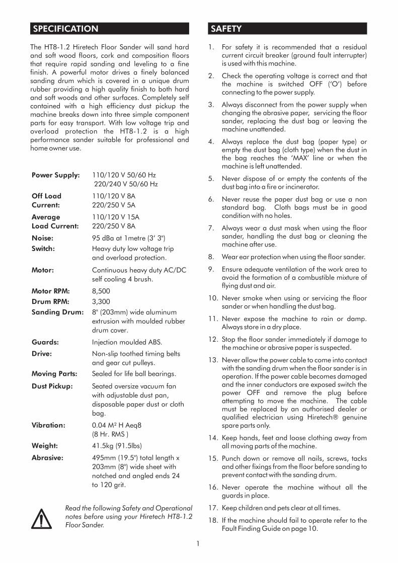
FLOOR SANDER MODEL HT8-1.2
OWNERS MANUAL & OPERATING INSTRUCTIONS
JULY 2003 REF. 179 PART # 163825
PRIN
TED
INTH
EU
K
© Hiretech
���
From Serial Number07294 (220/240 Volt) & 03415 (110/120 Volt)
NORTH AMERICAN SAFETY INSTRUCTIONS
USE AND APPLICATION
WARNING: This floor sanding machine must be grounded.
This floor-sanding machine shall be grounded while in use to protect the operator from electricshock. The machine is provided with a three-conductor cord and a moulded three-contactgrounding type attachment plug to fit the proper grounding type receptacle. The Green (orGreen and Yellow) conductor in the cord is the grounding wire. Never connect this wire to otherthan the grounding pin of the attachment plug.
This floor-sanding machine is provided with an attachment plug as shown in sketch A. It isintended for use on a nominal 120 volt circuit. If a properly grounded receptacle as shown insketch A is not available, an adaptor as shown in sketch 'C' should be installed as shown in sketchB if the outlet box that houses the receptacle is grounded. Be sure to fasten the grounding tab witha metal faceplate screw.
Floor sanding can result in an explosive mixture of fine dust and air. Use floor-sanding machineonly in a well-ventilated area free from any flame or match.
Moving Parts - to reduce the risk of injury, unplug the machine before replacing abrasive sheetsor carrying out any form of adjustment or servicing.
WARNING:
WARNING:
Risk of explosion.
Risk of potential injury.
This machine is intended for commercial use connected with the laying and maintaining of wooden floors anddecks.
These types of surfaces may be found both in commercial and household environments.
ATTACHMENT PLUG SKETCH ‘C’
METALSCREW
COVER OF GROUNDEDOUTLET BOX SKETCH ‘B’
ADAPTER
GROUNDINGMEANSCOVER OF GROUNDED
OUTLET BOX SKETCH ‘A’
GROUNDING PIN
CONTENTS
WARNING
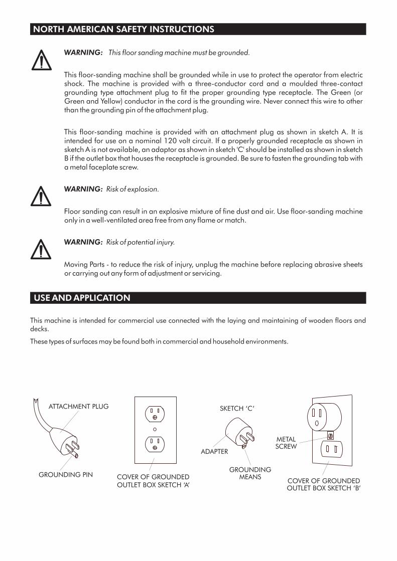
MAINS CABLE WIRING - PLUG
SPARE PARTS
SPECIFICATION
SAFETY
SET UP
PREPARATION
OPERATION
FLOOR SANDING TECHNIQUE
FLOOR TYPES
i
i
I
1
1
Assembly and Transport 2Installing Abrasive Disc 2
2
3
Drum Floor Sander 4Disc Floor Sander 4Orbital Floor Sander 4Hand Sanding 4
Sanding Plank & Strip Floors 4Veneered, Laminated & Thinner Floors 4
Parquet & Block Floors 5Between Coats of Finish (Varnish) 5
6
General 7Visual Inspection 7Drive Belts 7Dust Control System 7Lubrication 7Care of Motor 7,8Electrical Testing 9Sanding Drum 10
11
12,13
14, 15
16
16
17
FLOOR SANDER ABRASIVE GUIDE
SERVICE AND ROUTINE MAINTENANCE
FAULT FINDING
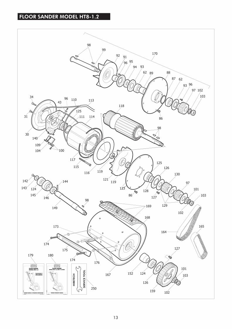
HT8-1.2 PARTS DRAWING
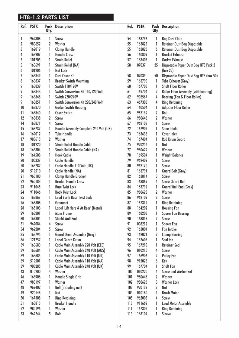
HT8-1.2 PARTS LIST
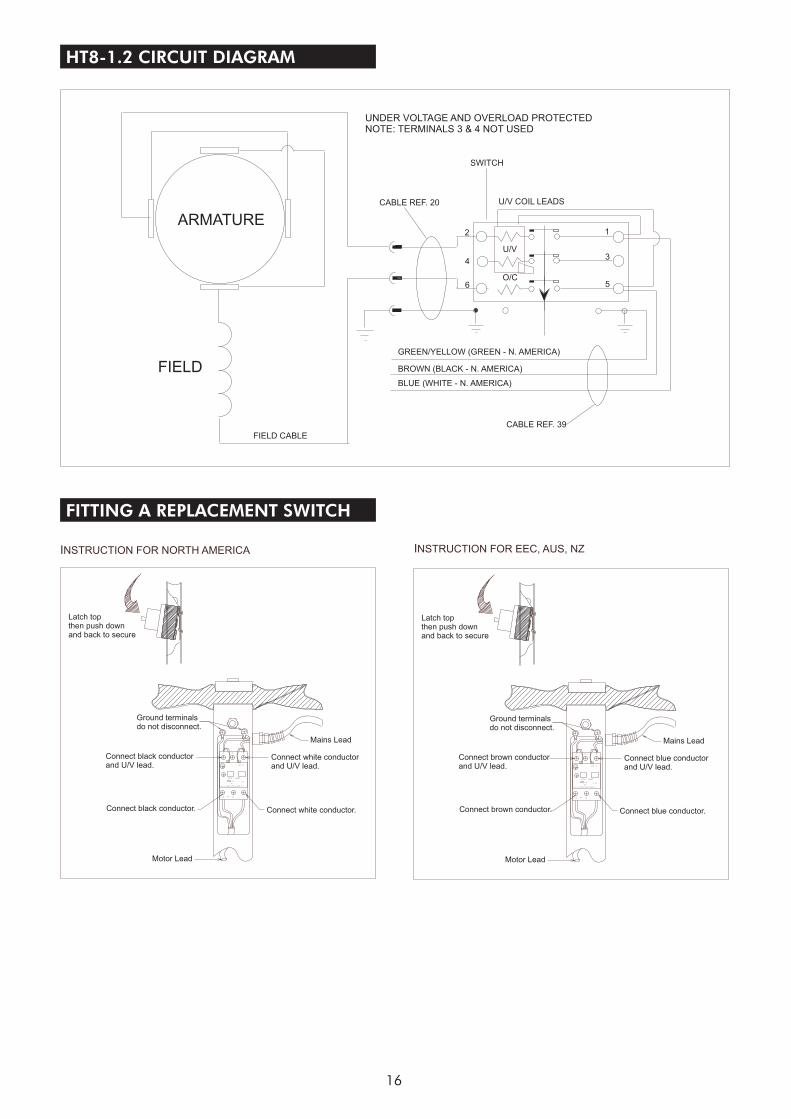
HT8-1.2 CIRCUIT DIAGRAM
FITTING A REPLACEMENT SWITCH
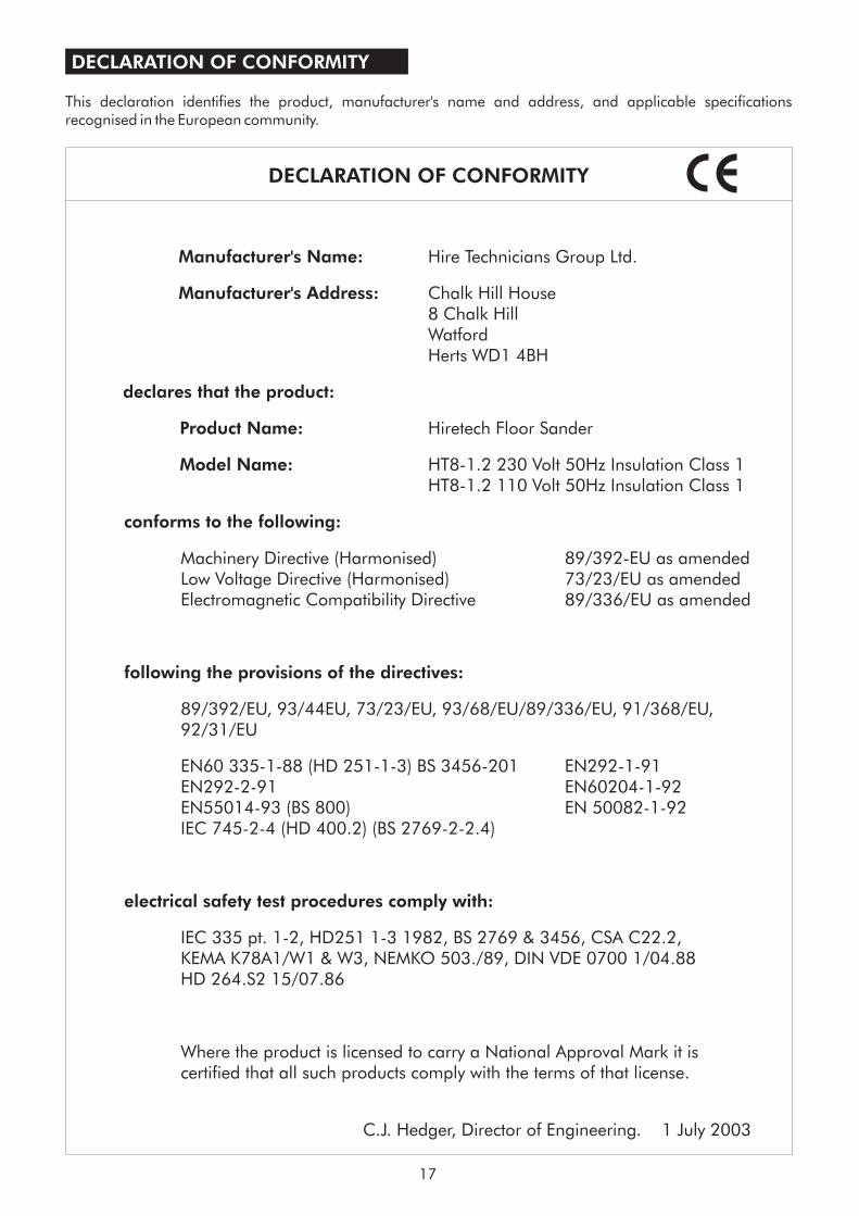
DECLARATION OF CONFORMITY
SERVICE & REPAIR 18
WARNING
MAINS CABLE WIRING - PLUG
For safe operation of this machine, read and understand all instructions. Look for the ‘warning/caution’ symbol.
This symbol means that if you do not follow the instructions injury can occur to the operator anddamage to the machine and floor may result.
Hiretech reserves the right to make changes or improvements to it's products without prior notice.®
i
NORTH AMERICA
BLACK
WHITE
GREEN
BRASSTERMINAL
SILVERTERMINAL
EU
BLUE BROWN
GREEN/YELLOW
UNITED KINGDOM
BLUE(N - NEUTRAL)
BROWN(L - LINE)
GREEN/YELLOW(E - EARTH)
SPARE PARTS
Use Hiretech genuine spare parts only for service and repair. Use of non-approved parts will void the productwarranty. See the back cover of this manual for the terms and conditions of the Hiretech Limited Warranty.
SPECIFICATION
The HT8-1.2 Hiretech Floor Sander will sand hardand soft wood floors, cork and composition floorsthat require rapid sanding and leveling to a finefinish. A powerful motor drives a finely balancedsanding drum which is covered in a unique drumrubber providing a high quality finish to both hardand soft woods and other surfaces. Completely selfcontained with a high efficiency dust pickup themachine breaks down into three simple componentparts for easy transport. With low voltage trip andoverload protection the HT8-1.2 is a highperformance sander suitable for professional andhome owner use.
SAFETY
1. For safety it is recommended that a residualcurrent circuit breaker (ground fault interrupter)is used with this machine.
2. Check the operating voltage is correct and thatthe machine is switched OFF (‘O’) beforeconnecting to the power supply.
3. Always disconnect from the power supply whenchanging the abrasive paper, servicing the floorsander, replacing the dust bag or leaving themachine unattended.
4. Always replace the dust bag (paper type) orempty the dust bag (cloth type) when the dust inthe bag reaches the ‘MAX’ line or when themachine is left unattended.
5. Never dispose of or empty the contents of thedust bag into a fire or incinerator.
6. Never reuse the paper dust bag or use a nonstandard bag. Cloth bags must be in goodcondition with no holes.
7. Always wear a dust mask when using the floorsander, handling the dust bag or cleaning themachine after use.
8. Wear ear protection when using the floor sander.
9. Ensure adequate ventilation of the work area toavoid the formation of a combustible mixture offlying dust and air.
10. Never smoke when using or servicing the floorsander or when handling the dust bag.
11. Never expose the machine to rain or damp.Always store in a dry place.
12. Stop the floor sander immediately if damage tothe machine or abrasive paper is suspected.
13. Never allow the power cable to come into contactwith the sanding drum when the floor sander is inoperation. If the power cable becomes damagedand the inner conductors are exposed switch thepower OFF and remove the plug beforeattempting to move the machine. The cablemust be replaced by an authorised dealer orqualified electrician using Hiretech® genuinespare parts only.
14. Keep hands, feet and loose clothing away fromall moving parts of the machine.
15. Punch down or remove all nails, screws, tacksand other fixings from the floor before sanding toprevent contact with the sanding drum.
16. Never operate the machine without all theguards in place.
17. Keep children and pets clear at all times.
18. If the machine should fail to operate refer to theFault Finding Guide on page 10.
1
Read the following Safety and Operationalnotes before using your Hiretech HT8-1.2Floor Sander.
Noise: 95 dBa at 1metre (3’ 3")
Switch: Heavy duty low voltage trip
and overload protection.
Motor RPM: 8,500
Drum RPM: 3,300
Guards: Injection moulded ABS.
Drive: Non-slip toothed timing belts
and gear cut pulleys.
Moving Parts: Sealed for life ball bearings.
Weight: 41.5kg (91.5lbs)
0.04 M² H Aeq8
(8 Hr. RMS )
495mm (19.5") total length x
203mm (8") wide sheet with
notched and angled ends 24
to 120 grit.
Abrasive:
Continuous heavy duty AC/DC
self cooling 4 brush.
8" (203mm) wide aluminum
extrusion with moulded rubber
drum cover.
Seated oversize vacuum fan
with adjustable dust pan,
disposable paper dust or cloth
bag.
Sanding Drum:
Dust Pickup:
Vibration:
Motor:
110/120 V 50/60 Hz
220/240 V 50/60 Hz
110/120 V 8A
220/250 V 5A
Average
Load Current:
110/120 V 15A
220/250 V 8A
Power Supply:
Off Load
Current:

SET UP
Assembly and Transport
Installing Abrasive Paper
1. The HT8-1.2 breaks down into three componentparts, the main body, handle assembly and dusttube for easy handling and transport. Toassemble loosen the Clamp Bracket Ref.21 andslide the handle assembly into the HandleBracket Ref.51. Adjust the height of the handleso that your arms are slightly bent when standingupright behind the machine. This will provideyou with maximum control in operation. Tightenthe clamp bracket firmly. Always ensure that theclamp bracket is tight, check periodically duringuse.
2. Connect the Cable Handle Ref.20 to the BodyTwist Lock Ref.24 at the rear right hand side of thefloor sander body. Align the plug with the pins,push in and twist clockwise to lock.
3. Slide the Exhaust Tube Ref.59 into the ExhaustBracket Ref.56 and push fully home.
4. Fit a paper dust bag following the instructionsprinted on the bag. If a cloth bag is used ensurethat it is tied securely around the dust tube neckand that the bag is in good condition with noholes.
5. To prepare the floor sander for use place themachine on the floor and remove the main cablefrom it's storage position on the handleassembly. Check that the cable is in goodcondition and that all fittings are secure.
6. To dismantle the floor sander reverse procedure1 to 5 above.
7. Always ensure that the floor sander is secure andcannot move when being transported in avehicle. The floor sander is heavy. Take carewhen lifting and carrying the machine.
1. Ensure the power cable is disconnected from thepower supply.
2. Tip the floor sander back so that it rests on thehandle.
3. Lift the Drum Guard Ref.35 and turn the DrumRef.168 to expose the Paper Clamp Bar Ref.175.Take care not to trap your fingers when turningthe drum.
4. Loosen the 2 Paper Clamp Screws Ref.174 with acoin or suitable screw driver so that the clampbar raises about 1/2“ (12mm) only. DO NOTremove the screws completely.
5. Select a suitable grade of abrasive paper (seeAbrasive Paper Guide on page 5). To help installcourse grit abrasive papers draw the smooth side
(back) of the paper over the edge of a workbench to make it curl .
6. Kneeling in front of the machine place one end ofthe abrasive paper under the clamp bar so thatthe notches align with the clamp bar screws andclamp bar.
Carefully holding the abrasive paper in placerotate the drum 1 revolution. Tuck the other endof the abrasive paper under the clamp bar anduse both hands to squeeze the sheet tight aroundthe drum. Make sure it is square to the edges ofthe drum with no overlap and both ends of theabrasive sheet are equal distance under thepaper clamp bar.
Firmly tighten the two clamp bar screws. Checkthe abrasive sheet is skin tight around the drum.If in doubt repeat the above procedure. Loose ordamaged abrasive sheets will tear duringsanding and can be expensive to keep replacing.Damage may also occur to the floor and floorsander.
7. Lower the drum guard and stand the machineup. The floor sander is now ready for use.
Note: Use Hiretech genuine floor sander abrasivesfor the best sanding performance and finish. Theywill also reduce the risk of tearing due to poor fitwhich is a common problem with generic and nonstandard abrasives.
1. Where possible remove all furniture from thearea or room. The HT8-1.2 Floor Sanderfeatures an efficient dust pickup, however, somedust will escape.
2. Remove all tacks, staples and other unwantedfixings from the floor. Failure to do so will resultin damage to the abrasive paper and sandingdrum.
3. Punch all nails below the surface of the floorusing a suitable nail punch and hammer. Anyscrews used to fix boards should be counter sunkbelow the surface. During sanding any nails orscrews that become exposed must be punched orcounter sunk further.
4. Firmly fix all loose boards or blocks.
5. Remove heavy wax, grease and dirt deposits byhand.
6. Sweep and vacuum the floor thoroughly toremove dirt and discarded fixings.
7. Ensure good ventilation by opening windows.
PREPARATION
2
OPERATION
1. Move the floor sander to the location of yourwork.
2. Connect the power cable to a suitable powersupply ideally located behind or to one side ofthe machine and work area.
3. Wear a dust mask and ear protection.
4. Hold both handles with the main cable held in asmall loop in the left hand and then passed overthe left shoulder.
5. Apply light downwards pressure on the handlesto tip the floor sander back to raise the sandingdrum off the floor. Switch on by pushing theON/OFF switch to the ‘I’ position.
6. Now move the floor sander slowly forward andat the same time release the pressure on thehandles to gently lower it so that the sandingdrum comes into contact with the floor.
7. Guide the floor sander in a straight line at a slowwalking pace. Do not force or hold the floorsander back. Allow the machine to do the workand always move at an even pace.
8. At the end of the pass while still moving forwardtilt the floor sander back so that the sandingdrum comes clear of the floor. Now movingbackwards lower the floor sander again and pullit backwards over the area just sanded moving ata steadily even pace. Take care to ensure thatthe power cable is kept clear of the sanding drumat all times. At the end of the sanding pass andwhile still moving backwards tilt the floor sanderback so once again the sanding drum comesclear of the floor.
Move the machine over so that it overlaps thearea just sanded by 3" (75mm) and start to sandthe next pass repeating the above technique.
i. Always ensure that the floor sander ismoving when in operation and thesanding drum is in contact with the floor.
ii. Never lift the back of the machine whensanding.
CAUTION - the HT8-1.2 Floor Sander is apowerful machine. Always ensure thatyou have a firm grip before switching on.
CAUTION - to prevent damage to thefloor surface, work piece or machinefollow these rules.
3
iii. Never apply pressure to try to increase therate of sanding. Damage to the floor andmachine will occur.
iv. Never bounce or drop the floor sander onto the floor. Always lower the machinegently.
v. Never dwell in one place, move steadily atall times.
vi. Never allow the power cable to come intocontact with the sanding drum.
9. When the dust in the dust bag reaches the ‘MAX’line stop sanding. Disconnect the power cablefrom the power supply and remove the paperdust bag. Turn the top of the paper dust bag overto stop the escape of dust and dispose of into asuitable container. Never reuse the paper dustbag or empty it or dispose of it into a fire. If acloth bag is used empty into a suitable containerbeing careful to contain the dust. Do not disposeof the contents into a fire.
10. Fit a new paper dust bag or refit the cloth bag.Reconnect the floor sander to the power supplyand continue sanding.
11. When taking a break from work disconnect thepower cable from the supply, remove anddispose of the paper dust bag, or empty the clothbag as detailed in 8. above. Never leave thefloor sander unattended with the dust bag inplace containing dust.
12. On completion disconnect the power cable fromthe supply. Remove and dispose of the paperdust bag, or empty the cloth bag as detailed in 8.above. Stow the cable on the handle assemblyand if required dismantle for transportation.Carry out maintenance as recommended inMaintenance and Servicing.
DANGER - never leave the floor sanderunattended with dust in the dust bag.Always remove the dust bag and disposeof into a suitable container.

FLOOR SANDING TECHNIQUE
HT8-1.2 Floor Sander (Drum)
HT7-2 Disc Floor Sander (Edger)
HTF-2 Floor Sander (Orbital)
Hand Sanding
- a powerful floorsander designed for the rapid leveling and sanding ofall types of wood flooring excluding thin laminated orveneered floors. Load the sander with abrasivemaking sure that it is skin tight around the drum.Loose sheets will tear. Place the sander on the righthand wall (unless you are making an angled cut onuneven floors) with about two thirds of the floor infront of you. Start the sander with the drum off thefloor then walk forward at an even pace and ease thedrum on to the floor. As you near the end of the pass,gradually raise the drum off the floor. Practice thistechnique before turning on the sander.
Cover the same path you made on the forward cut bypulling the machine backwards and easing the drumto the floor as you begin the backward pass until youreach the original starting point, then ease the drumoff the floor.
When two thirds of the floor is sanded, turn the floorsander around and sand the remaining third in thesame way. Overlap the one third area by 0.6 to 0.9meters (2 to 3 feet ) with the two thirds area to blendthe two areas together.
- a powerful discfloor sander designed for sanding along the edgesof a floor without damaging the baseboards ormoldings. Also suitable for smaller areas where theHT8-1.2 Floor Sander will not reach like stair treadsand closets load the abrasive disc making sure theretaining bolt is tight. Start the edger with the disc offthe floor then lower the disc to the floor as you movethe sander. Work progressively moving the sander ina sweeping motion from side to side.
- a orbital actionfloor sander designed for re-finishing, sandingbetween coats of varnish and re-surfacing floors ingood condition. load the abrasive sheet, pad or strip.Start the sander, move immediately and sand in thedirection of the grain using the same technique as thedrum floor sander. For difficult to reach areas use thedisc floor sander with a fine grit abrasive, or sand byhand.
- to sand difficult to reach areasscrape and sand the floor by hand. Use a scraper toremove old finishes, always scraping in the directionof the grain, and then sand by hand using the samegrit abrasive as you finished with when machinesanding. See Floor Sanding Technique diagrams onpage 5.
WARNING - never bounce the sandingdrum or dwell in one place as this willsand dips and hollows in the floor.
FLOOR TYPES
PLANK & STRIP FLOORS
VENEERED, LAMINATED & THINNER FLOORS
Old floors in good condition
Uneven floors
Floors with an existing finish
- when the floor is ingood condition - no uneven edges, cupping orcrowning of planks and strips - and you want to re-surface the floor, sanding back to new wood, startsanding in the direction of the planks or strips - withthe wood grain. Start with a medium grit abrasive.Complete the first cut with the HT8-1.2 Floor Sanderthen sand up to the baseboards and door thresholdswith the HT7-2 Disc Floor Sander, using a mediumgrit abrasive, blending the edges in with the mainfloor area. Sweep the floor. Using a medium/fine gritabrasive, sand the main floor area with the drumsander and then complete the floor with the edgerusing a fine grit abrasive. Sweep the floor. Finishsanding the main floor area with the drum floorsander using a fine grit abrasive. If the floor is inparticularly good condition (level with no deepscratches or blemishes) you may re-surface the floorusing the HTF-2 Floor Sander, however, as thesanding action of this machine is less aggressive thanthe HT81.2 Floor Sander the job will take more time.
- when the floor is uneven sand
diagonally at 45 across the room in both directionsusing the HT8-1.2 Floor Sander with a coarse gritabrasive. Only make one cut on both diagonals, thiswill achieve a basic level. Now complete the floor asfor a level strip or plank floor. Use the same gritabrasive as was used on the 45 cut for the first cutparallel to the planks or strips.
- when re-finishing afloor remove as little of the existing surface aspossible. If the old finish is worn and the floor isgenerally in good condition use the HTF-2 FloorSander with Hiretech abrasive pads and strips whichhave been especially designed for re-finishing floors.These will maintain the integrity of any stain used tocolour the wood and prepare the surface for a newcoat of finish. If the floor is badly marked andscratched and has to be sanded back to new wooduse the HT8-1.2 Floor Sander and HT7-2 Disc FloorSander. Always try a medium grit paper first,particularly on a diagonal cut. If 90% of the old finishis removed and the floor is generally leveled, you donot need to use a coarse grit abrasive.
Use the HTF-2 Floor Sander for veneered andlaminated floors or thinner floors that may have beensubjected to repeated sanding. The HTF-2 willremove old surface finishes and prepare the floor forre-finishing. Sand the floor using the same methodas a strip, plank, or parquet floor. If the floor hasdeeper scratches or marks these should be sanded
o
o
4

5
out by hand and blended in with the main floor. Tocheck the wood depth in the floor remove abaseboard or molding from around the edge of thefloor. This should provide access to the edge of thefloor for inspection.
The grain of the wood will run in a number ofdirections so sand the floor in the direction of themain source of natural light in the room. If there is nosource of natural light sand in the direction of thelongest side of the room or, if the room is square, inthe direction the furniture is laid out and how peoplenormally use and view the room.
This technique will help mask any imperfections in the
PARQUET & BLOCK FLOORS
floor. Complete the sanding operation as detailedfor plank or strip floors.
Use the HTF-2 Floor Sander to sand between coats offloor finish, particularly when using water basedvarnishes. These types of finishes tend to raise thewood grain when first applied to raw wood. Alloweach coat of varnish to dry completely following themanufactures directions. Use Hiretech abrasive padsto sand between each coat of varnish. The fineabrasive pads will remove light brush/applicatormarks and raised grain while maintaining theintegrity of the coat of varnish applied
BETWEEN COATS OF FINISH (VARNISH)
unsanded boardssanded boards
level very unevenfloors by sandingdiagonally in both
directions
unsanded boards
unsanded boards
Level uneven floors.
Sand main floor area.
Sand and blend edges in with main floor area.
FLOOR SANDING TECHNIQUE
Plank and Strip Floors
Parquet and Wood Block Floor
- sand in thedirection the boards are laid, with thewood grain.
-sand in the direction of the mainsource of natural light. If there is nonatural source of light, sand in thedirection of the longest side of theroom. If the room is square, sand inthe direction the furniture is laid outand how people normally use theroom.
s
6
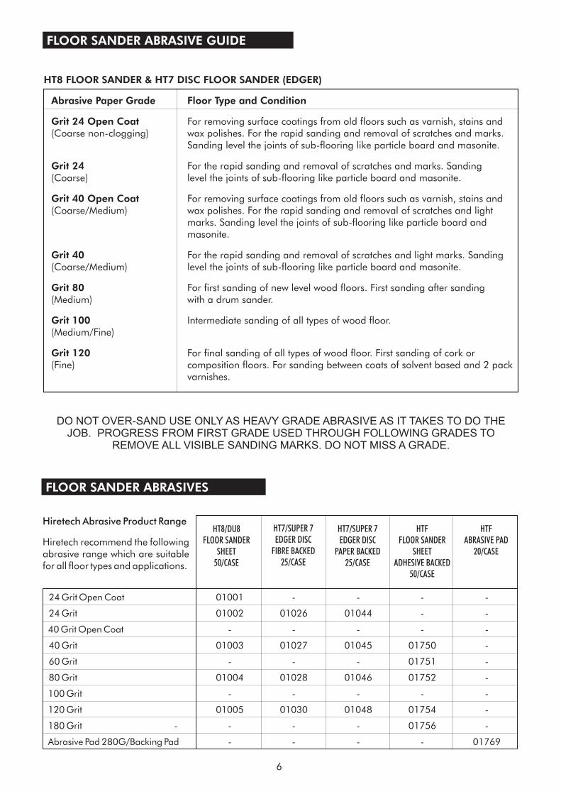
HT8 FLOOR SANDER & HT7 DISC FLOOR SANDER (EDGER)
Grit 24
Grit 40
Abrasive Paper Grade Floor Type and Condition
Grit 24 Open Coat
Grit 40 Open Coat
Grit 80
Grit 100
Grit 120
For removing surface coatings from old floors such as varnish, stains andwax polishes. For the rapid sanding and removal of scratches and marks.Sanding level the joints of sub-flooring like particle board and masonite.
For removing surface coatings from old floors such as varnish, stains andwax polishes. For the rapid sanding and removal of scratches and lightmarks. Sanding level the joints of sub-flooring like particle board andmasonite.
For first sanding of new level wood floors. First sanding after sanding(Medium) with a drum sander.
Intermediate sanding of all types of wood floor.(Medium/Fine)
For final sanding of all types of wood floor. First sanding of cork or(Fine) composition floors. For sanding between coats of solvent based and 2 pack
varnishes.
(Coarse non-clogging)
For the rapid sanding and removal of scratches and marks. Sanding(Coarse) level the joints of sub-flooring like particle board and masonite.
(Coarse/Medium)
For the rapid sanding and removal of scratches and light marks. Sanding(Coarse/Medium) level the joints of sub-flooring like particle board and masonite.
FLOOR SANDER ABRASIVE GUIDE
DO NOT OVER-SAND USE ONLY AS HEAVY GRADE ABRASIVE AS IT TAKES TO DO THEJOB. PROGRESS FROM FIRST GRADE USED THROUGH FOLLOWING GRADES TO
REMOVE ALL VISIBLE SANDING MARKS. DO NOT MISS A GRADE.
FLOOR SANDER ABRASIVES
24 Grit Open Coat 01001 - - - -
24 Grit 01002 01026 01044 - -
40 Grit Open Coat - - - - -
40 Grit 01003 01027 01045 01750 -
60 Grit - - - 01751 -
80 Grit 01004 01028 01046 01752 -
100 Grit - - - - -
120 Grit 01005 01030 01048 01754 -
180 Grit - - - - 01756 -
Abrasive Pad 280G/Backing Pad - - - - 01769
HT8/DU8FLOOR SANDER
SHEET50/CASE
HT7/SUPER 7EDGER DISC
FIBRE BACKED25/CASE
HT7/SUPER 7EDGER DISC
PAPER BACKED25/CASE
HTFFLOOR SANDER
SHEETADHESIVE BACKED
50/CASE
HTFABRASIVE PAD
20/CASE
Hiretech Abrasive Product Range
Hiretech recommend the followingabrasive range which are suitablefor all floor types and applications.
SERVICE & ROUTINE MAINTENANCE
CAUTION - maintenance and repairsmust be carried out by authorisedpersonnel only. To prevent injury, alwaysremove the power cable from the powersupply before undertaking any work onthe machine. Do not operate the floorsander unless it is fully assembled and allguards are in place. Use Hiretechgenuine spare parts only.
General
Visual Inspection
1. Always make a list when first examining themachine, to remind you of parts or actionneeded on completion of repair/service.
2. The HT8-1.2 is subject to high speeds. All screwsshould be fitted using a suitable thread lockcompound.
3. On completion of any work or service on anelectrical tool or appliance statutory safety testsmust be carried out by a competent person andrecorded (see Testing for Electrical Safety page8).
4. The HT8-1.2 needs no lubrication during routineservicing.
5. Always ensure that the electrical supply isdisconnected before starting any routineservicing or repair.
1. Check that the drum guard Ref.35 is in goodcondition and functioning correctly. Ensure thatthe Warning Label Ref.36 is present and legible.
2. Check all other guards and mechanical parts arein good condition.
3. Examine the power cable Ref.39 and the handlecable Ref.20. If the outer insulation shows theslightest of abrasions or the inner conductors areexposed, then the cable must be replaced. Thecable must not be repaired with tape orinsulation sleeve
4. Examine both the mains plug and theinterconnecting socket, Body Twist Lock Ref.24.The plugs must be opened and examined (seeElectrical Testing page 8).
5. If a cloth type bag is in service check thecondition, old clogged cloth dust bags make foran inefficient dust pickup.
6. Ensure that all labels are present and in goodcondition.
Drive Belts
Dust Control System
Lubrication
Care of Motor
1. To examine the condition of the Drive BeltsRef.164 and Ref.165 remove the four screwsRef.83 and the Belt Guard Ref.81.
2. Lift the Fan Belt Ref.165 while rotating the pulleyremove the fan belt. Repeat for the Drum BeltRef.164.
3. Examine the pulleys for wear, worn or damagedpulleys should be replaced
4. To reduce the instance of belt breakage, examinethe drive belts, look for cracks or fraying andreplace if necessary with new belts. To replacereverse the above procedure taking care to avoidbending the belts tighter than the pulley diameteras this can result in damaged belts. Refit the beltguard.
1. For efficient dust pick up ensure that cloth typedust bags are clean and unclogged and that theintake is clear and properly adjusted.
2. Turn the machine on to its side and loosen thethree Screws Ref.71 and remove the Dust ShoeRef.72 and clear any obstruction. The grit fromthe abrasive paper can wear away the leadingedge of the dust shoe, if this has occurred thenfile or grind the leading edge level beforerefitting.
Install the dust shoe ensuring that the clearancebetween the shoe and the drum is maintained at3/8“ (10mm).
1. The HT8-1.2 is completely lubricated. Thebearings are sealed and do not requirelubrication. In the unlikely event that a bearingrequires replacement use a Hiretech genuinespare part only as the grease contained in thesebearings is special. A standard bearing is notsuitable and may result in further damage.
1. The motor must be kept free from grease anddust.
2. The motor brushes must be checked regularly,inspect the brushes every three months or every500 hours of use, whichever comes first.
3. Replace ALL FOUR motor brushes when any onebrush has worn to 12mm ( / ”) or less in length.
Brushes MUST slide freely in the brush holders.
CAUTION - take care to avoid trappingyour fingers when removing or replacingthe drive belts.
15
32
7
4. To inspect and replace motor Brushes Ref.104,with the brush block assembly removed.
i. Remove the three Screws Ref.82 andremove the Wall End Guard Ref.84 toexpose the motor brush assembly.
ii. Remove the four retaining Screws Ref.31from the Shield Wall End Ref.30, insert twoof the screws into the ‘jacking holes’situated adjacent to the countersunkretaining holes.
iii. Carefully tighten these screws until theshield wall end is jacked clear of the outercasting. Withdraw the shield-wall end.
iv. With the brush block assembly completeand the connecting leads still attached.You will note that as the brush blockassembly is withdrawn the brushes springtowards the center and often the brushsprings fall clear as the brushes are nolonger at the height to retain them. Takecare not to lose any springs.
v. To remove a brush spring with a brush inthe operating position push the brushspring down and towards the brush and liftout.
vi. Using a cross recess screwdriver removethe four brush shunt (pigtail) retainingScrews Ref.105 and lock Washers Ref.100.
vii. Remove the four brushes. Remove the two‘jacking’ screws.
viii. Thoroughly clean the brush assembly andhousing using a soft brush and a suitablevacuum cleaner.
ix. Inspect the four brushes for damage orwear and if any one brush is found to bedamaged or worn to a length of 5/8“(16mm) or less in length then replace allfour brushes.
x. When replacing brushes ensure freemovement in each brush holder and fit thebrush with the shunt (pigtail) towards thefield coil. Ensure that each brush shunt isconnected securely with the screw, andlock washer, two spare screws and lockwashers are provided with each pack ofbrushes. Do not fit the brush springs at thisstage.
xi. Pull each brush up to the top of the holderusing the shunt wire to retain it in thisposition for the next stage.
xii. Enter the assembly into the main frametaking care to avoid contact between thebrushes and the commutator of thearmature, that the shield wall end is
correctly aligned with the main frame andthat no leads are trapped. There is adepressed pattern on the shield wall endand on the main frame to assist alignment.Both the bearing fit and the main frame fitare ‘light contact’ and may require lightlytapping into position using a soft mallet.DO NOT FORCE.
xiii. Replace and tighten the four countersunkScrews Ref.31.
xiv. Remove the four brush block retainingScrews Ref.31 and the single timing ScrewRef.34 from the Shield-Wall End Ref.30.The brush block assembly is now free torotate. To fit the brush springs rotate thebrush block assembly counter clockwise(over towards the rear of the machine) untilthe lower brush holder is accessible, fit thebrush spring by inserting into the holderwith the coil spring over the brush thenpush down until the tag comes into contactwith the holder, slide the tag away from thebrush and release. The brush spring willclip into position. Check the spring andbrush for correct alignment and freemovement.
xv. Rotate the brush block assembly clockwiseand repeat to fit the remaining threesprings. The switch and field cablesrestrict the movement of the brush blockassembly, take care not to loosen ordamage these cables.
xvi. Return the brush block assembly to itsoriginal position and align the timingnotch in the block with the timing hole,screw the timing Screw Ref.34 intoposition.
xvii. Secure the brush block assembly using theremaining four screws Ref.34. DO NOTOVER TIGHTEN.
xviii. Finally check that all cables are well clearof moving parts before refitting the guardwall and securing with the 3 ScrewsRef.82..
Note: To inspect and replace the motor brushes whileretaining the brush block assembly in place repeatthe procedure xiv. to xviii. above.
8
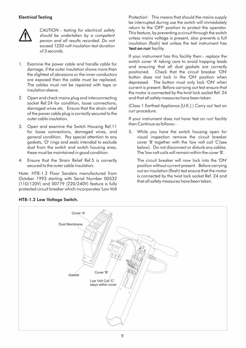
Electrical Testing
CAUTION - testing for electrical safetyshould be undertaken by a competentperson and all results recorded. Do notexceed 1250 volt insulation test durationof 3 seconds.
1. Examine the power cable and handle cable fordamage, if the outer insulation shows more thanthe slightest of abrasions or the inner conductorsare exposed then the cable must be replaced.The cables must not be repaired with tape orinsulation sleeve.
2. Open and check mains plug and interconnectingsocket Ref.24 for condition, loose connections,damaged wires etc. Ensure that the strain reliefof the power cable plug is correctly secured to theouter cable insulation.
3. Open and examine the Switch Housing Ref.11for loose connections, damaged wires, andgeneral condition. Pay special attention to anygaskets, 'O' rings and seals intended to excludedust from the switch and switch housing area,these must be maintained in good condition.
4. Ensure that the Strain Relief Ref.5 is correctlysecured to the outer cable insulation.
Note: HT8-1.2 Floor Sanders manufactured fromOctober 1993 starting with Serial Number 00532(110/120V) and 00779 (220/240V) feature a fullyprotected circuit breaker which incorporates 'Low Volt
Protection'. This means that should the mains supplybe interrupted during use the switch will immediatelyreturn to the 'OFF' position to protect the operator.This feature, by preventing a circuit through the switchunless mains voltage is present, also prevents a fullinsulation (flash) test unless the test instrument has' ' facility.
If your instrument has this facility then:- replace theswitch cover 'A' taking care to avoid trapping leadsand ensuring that all dust gaskets are correctlypositioned. Check that the circuit breaker 'ON'button does not lock in the 'ON' position whendepressed. The button must only lock 'ON' whencurrent is present. Before carrying out test ensure thatthe motor is connected by the twist lock socket Ref. 24and that all safety measures have been taken.
(Class 1 Earthed Appliance [U.K.] ) Carry out 'test onrun' procedure.
If your instrument does not have 'test on run' facilitythen Continue as follows:-
5. While you have the switch housing open forvisual inspection remove the circuit breakercover 'B' together with the 'low volt coil 'C'(seebelow). Do not disconnect or disturb any cables.The 'low volt coils will remain within the cover 'B'.
The circuit breaker will now lock into the 'ON'position without current present. Before carryingout an insulation (flash) test ensure that the motoris connected by the twist lock socket Ref. 24 andthat all safety measures have been taken.
test on run
9
HT8-1.2 Low Voltage Switch.
CE 0 UAC690V CSN EN 60947
START
STOP
6
4
2
?? ??-??A
TESTAC 3
SM1-105
OEZ3
1
Cover 'B'
Low Volt Coil 'C'stays within cover
Gasket
Cover 'A'
Dust Membrane
6. Using standard procedure test for electricalsafety (Class 1 Earthed Appliance [U.K.] ). Donot exceed 1250 volt flash duration of 3 seconds.
7. Record the test results.
8. Complete a functional (run) test and recordresults.
9. After carrying out the tests disconnect themachine from the test station and snap the 'LowVolt Coil' 'C' back into position and replace cover'B'.
10. Replace the switch cover 'A' taking care to avoidtrapping leads and ensuring that all dust gasketsare correctly positioned. Check that the circuitbreaker 'ON' button does not lock in the 'ON'position when depressed. The button must onlylock 'ON' when current is present.
11. Finally test the machine once again to ensuregood earth and insulation of the mains cableand switch. Do not exceed 1250 volt flashduration of 3 seconds.
1. Check that power supply is disconnected. Tilt themachine back and rest the handle on the floor.Open the drum guard and examine the drumcover. A damaged or worn cover must bereplaced to maintain machine performance. Adamaged or worn cover can result in poorsanding with subsequent damage to the floorsurface and can be dangerous in operation. Acover that is worn to 1/4“ (6mm) or less inthickness must be replaced.
2. To replace the drum cover see the detailedinstructions included in each genuine Hiretech®Drum Cover Kit Ref.167 Part # 162312. The useof an impact screwdriver may assist.
3. It is recommended that at each service intervalthe drum cover is checked and trimmed(dressed) if necessary to provide a true uniformdiameter.
4. First check that the rear castors are properlyadjusted. Remove the 4 Screws Ref.83 and theBelt Guard Ref.81. Check that the factory markis present and aligned on the rear castor adjusterRef.64 and main frame. Adjust as necessary byloosening the two clamp Bolts Ref.65 andadjusting the cam.
CAUTION - when undertaking afunctional test ensure that the machine issecure, remember the sanding drum willrotate, ensure that the drum cannot comeinto contact with the work bench/servicearea.
Sanding Drum.
10
If the machine has no factory mark on theadjuster and main frame then it is a later typemachine that uses a concentric support insteadof an adjuster. No adjustment is required.
5. Fit a sheet of fine grit abrasive paper (120 grit),abrasive side up on to a level floor surface.Remove any abrasive paper from the drum andre-tighten the clamp bar screws. Make sure theclamp bar screws are tight.
Position the floor sander over the abrasive paperand connect the power cable to the powersupply. Tip the floor sander back to raise thesanding drum off the floor and switch on.
Gently lower the floor sander so the sandingdrum 'just' touches the abrasive paper. Hold thesander in position for a few seconds then tip backand switch off.
Disconnect the power cable and tip the floorsander back so that it rests on it's handle. Lift thedrum guard and check the condition of the drumcover. If it is uniform an even surface will bewitnessed, if not, continue to dress the drum untilall high and low spots are removed. Take carenot to remove too much material as this willreduce the life of the drum cover.
6. When a uniform surface is achieved it isadvisable to slightly ‘feather’ both edges of thedrum cover. Switch off and disconnect the powercable from the power supply. Tilt the machineback and lift the drum guard to expose the drumcover. Using a medium to fine grit abrasivepaper carefully feather the edge of both sides ofthe drum cover by holding the abrasive paperagainst the edge and rotating the drum. Becareful not to trap your fingers. The softer edgeprovided will help prevent ‘cut’ lines witnessedon the floor surface when sanding particularly insofter woods. Always feather the edges of a newdrum cover.
Note: On earlier models the line stamped on theadjuster and main frame has been set in the factory atthe time of manufacture. Never change, deface oralter this line.
WARNING - the sanding drum and drumcover must be correctly adjusted andmaintained to ensure the best sandingperformance. Failure to do so can resultin damage to the floor surface and canbe dangerous.
11
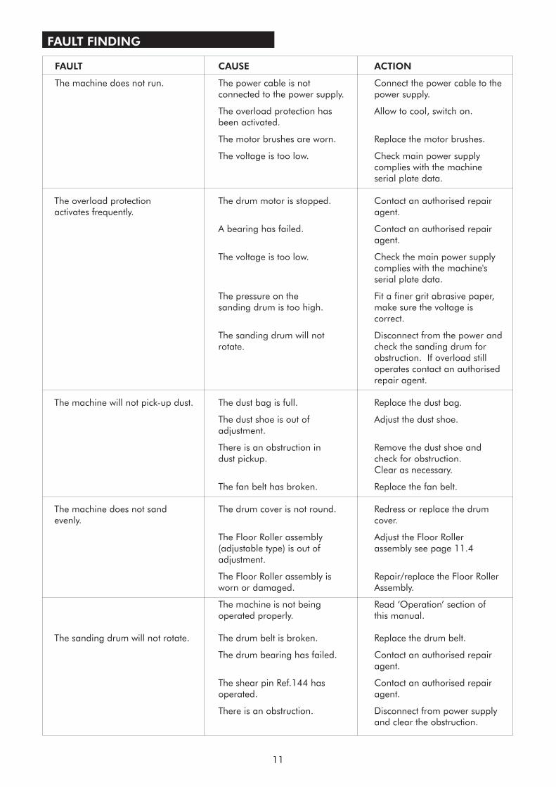
FAULT FINDING
FAULT CAUSE ACTION
The machine does not run. The power cable is not Connect the power cable to theconnected to the power supply. power supply.
The overload protection has Allow to cool, switch on.been activated.
The motor brushes are worn. Replace the motor brushes.
The voltage is too low. Check main power supplycomplies with the machineserial plate data.
The overload protection The drum motor is stopped. Contact an authorised repairactivates frequently. agent.
A bearing has failed. Contact an authorised repairagent.
The voltage is too low. Check the main power supplycomplies with the machine'sserial plate data.
The pressure on the Fit a finer grit abrasive paper,sanding drum is too high. make sure the voltage is
correct.
The sanding drum will not Disconnect from the power androtate. check the sanding drum for
obstruction. If overload stilloperates contact an authorisedrepair agent.
The machine will not pick-up dust. The dust bag is full. Replace the dust bag.
The dust shoe is out of Adjust the dust shoe.adjustment.
There is an obstruction in Remove the dust shoe anddust pickup. check for obstruction.
Clear as necessary.
The fan belt has broken. Replace the fan belt.
The machine does not sand The drum cover is not round. Redress or replace the drumevenly. cover.
The Floor Roller assembly Adjust the Floor Roller(adjustable type) is out of a
The Floor Roller assembly is Repair/replace the Floor Rollerworn or damaged. Assembly.
The machine is not being Read ‘Operation’ section ofoperated properly. this manual.
The sanding drum will not rotate. The drum belt is broken. Replace the drum belt.
The drum bearing has failed. Contact an authorised repairagent.
The shear pin Ref.144 has Contact an authorised repairoperated. agent.
There is an obstruction. Disconnect from power supplyand clear the obstruction.
ssembly see page 11.4adjustment.
12
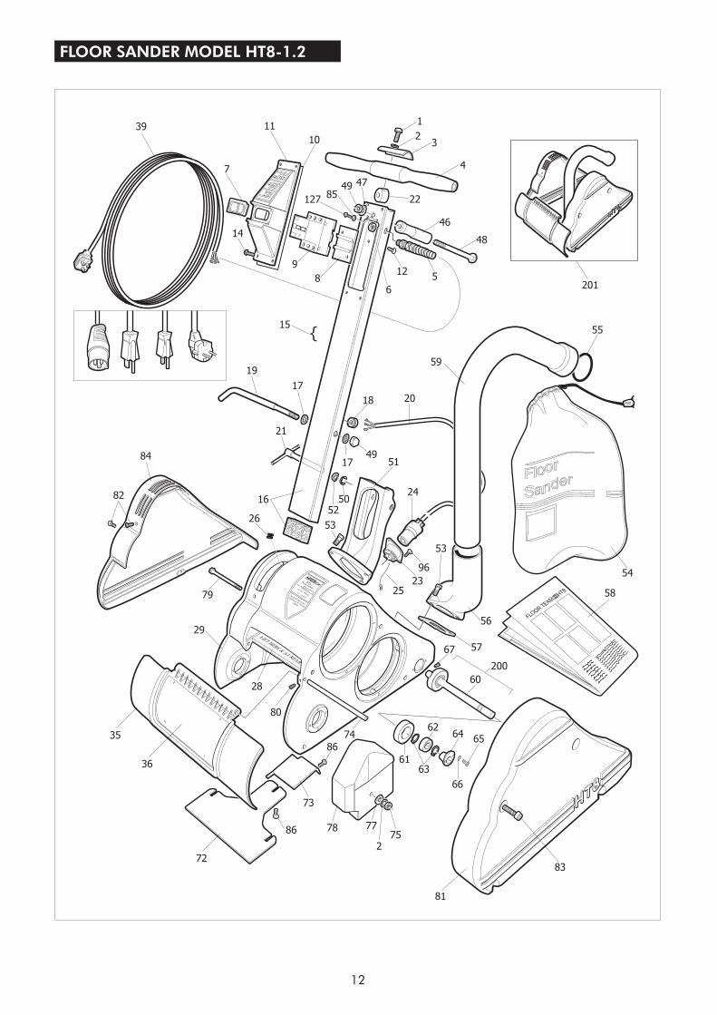
FLOOR SANDER MODEL HT8-1.2
39
7
11
10
14
19
15
16
26
21
17
17
18
49
20
59
55
24
51
52
53
50
96
53
56
67
60
65
66
64
6361
62
83
81
752
7886
73
72
36
35
28
80
79
29
84
82
77
86
74
58
5423
9
1
23
4
48
46
22
12
6
58
12785
49 47
25
200
57
201
{
13
FLOOR SANDER MODEL HT8-1.2
142
143 124
145
144
146
149
98
173
176
174
175
174
167
250
127
152 124
126
159
101
103
102
168
169
165
164
179 180
31
30140
109
104 100
117
115
116 119
121119
123
86127
125
128
126
130
97
101
103
102
129
11043
96113
125
111 114
118
98
34
OWNERS WORKSHOP MANUALOWNERS WORKSHOP MANUAL
NOVEMBER 2000NOVEMBER 2000 REF. 180 PART # 163825REF. 180 PART # 163825
PRIN
TED
INTH
EU
KPRIN
TED
INTH
EU
K
FLOOR SANDERMODEL HT8-1.2, HT8-1 & DU8R
FLOOR SANDERMODEL HT8-1.2, HT8-1 & DU8R
FLOOR SANDER
MODEL HT8-1.2
FLOOR SANDER
MODEL HT8-1.2
OWNERS MANUAL & OPERATING INSTRUCTIONSOWNERS MANUAL & OPERATING INSTRUCTIONS
From Serial Number03415 - 110/120 Volt07294 - 220/240 Volt
From Serial Number03415 - 110/120 Volt07294 - 220/240 Volt
NOVEMBER 2000NOVEMBER 2000 REF. 179 PART # 163825REF. 179 PART # 163825
PRIN
TED
INTH
EU
KPRIN
TED
INTH
EU
K
98
99
92 91
96 95
93
170
62 89 88
87 62
93 96
97 102
103
86
94
HIR
ETEC
H
SERV
ICE
TO
OL
14
HT8-1.2 PARTS LIST
1 962308 1 Screw2 980652 2 Washer3 162019 1 Clamp Handle4 163907 1 Handle Cross5 101205 1 Strain Relief5 163691 1 Strain Relief (NA)6 101206 1 Nut Lock7 163849 1 Dust Cover Kit8 163837 1 Bracket Switch Mounting9 163839 1 Switch 110/120V9 163843 1 Switch Conversion Kit 110/120 Volt9 163848 1 Switch 220/240V9 163851 1 Switch Conversion Kit 220/240 Volt10 163870 1 Gasket Switch Housing11 163840 1 Cover Switch12 163838 2 Screw14 163871 4 Screw15 163737 1 Handle Assembly Complete 240 Volt (UK)16 169012 1 Tube Handle17 980615 2 Washer18 101220 1 Strain Relief Handle Cable18 163804 1 Strain Relief Handle Cable (NA)19 164508 1 Hook Cable20 100337 1 Cable Handle20 163782 1 Cable Handle 110 Volt (UK)20 519510 1 Cable Handle (NA)21 960180 1 Clamp Handle Bracket22 960183 1 Bracket Handle Cross23 911045 1 Base Twist Lock24 911046 1 Body Twist Lock25 163867 1 Lead Earth Base Twist Lock26 163808 1 Grommet28 165103 1 Label 'Lift Here & At Rear' (Metal)29 163201 1 Main Frame30 167804 1 Shield Wall End31 962084 4 Screw34 962204 5 Screw35 163795 1 Guard Drum Assembly (Grey)36 121252 1 Label Guard Drum39 163683 1 Cable Main Assembly 220 Volt (EEC)39 163684 1 Cable Main Assembly 240 Volt (AUS)39 163685 1 Cable Main Assembly 110 Volt (UK)39 519501 1 Cable Main Assembly 110 Volt (NA)39 908285 1 Cable Main Assembly 240 Volt (UK)43 010200 4 Washer46 163906 1 Handle Single Grip47 980197 1 Washer48 962402 1 Bolt (including nut)49 920148 1 Nut50 167308 1 Ring Retaining51 160815 1 Bracket Handle52 980196 1 Washer53 962244 5 Bolt
54 163796 1 Bag Dust Cloth55 163823 1 Retainer Dust Bag Disposable55 163826 6 Retainer Dust Bag Disposable56 160809 1 Bracket Exhaust57 163403 1 Gasket Exhaust58 07037 25 Disposable Paper Dust Bag HT8 Pack 2
(box 25)58 07039 50 Disposable Paper Dust Bag HT8 (box 50)59 163790 1 Tube Exhaust (Grey)60 167708 1 Shaft Floor Roller61 169704 2 Roller Floor Assembly (with bearing)62 902567 4 Bearing (Fan & Floor Roller)63 467308 4 Ring Retaining64 160504 1 Adjuster Floor Roller65 962139 2 Bolt66 980646 2 Washer67 962103 1 Screw72 167902 1 Shoe Intake73 163636 1 Cover Inlet74 167404 1 Rod Drum Guard75 920256 1 Nut77 980629 1 Washer78 169504 1 Weight Balance79 962409 1 Screw80 962170 1 Screw81 163791 1 Guard Belt (Grey)82 163814 3 Screw83 163869 4 Screw Guard Belt84 163792 1 Guard Wall End (Grey)85 980623 2 Washer86 962109 8 Screw87 167312 1 Ring Retaining88 164202 1 Housing Fan89 168203 1 Spacer Fan Bearing90 163813 2 Screw91 008212 1 Spacer Fan92 163004 1 Fan Intake93 162021 2 Clamp Bearing94 167608 1 Seal fan95 167210 1 Retainer Seal96 010210 4 Screw97 166906 2 Pulley Fan98 915028 6 Key99 167704 1 Shaft Fan100 010220 4 Screw and Washer Set101 980648 2 Washer102 980626 3 Washer Lock103 920132 3 Nut104 010180 4 Brush Motor105 962003 4 Screw110 911662 1 Lead Motor Assembly111 167302 1 Ring Retaining113 168104 1 Sleeve
Ref. PSTK Pack DescriptionQty.
Ref. PSTK Pack DescriptionQty.

HT8-1.2 PARTS LIST
114 163104 1 Field 110/120 Volt HT8114 163112 1 Field 220/240 Volt HT8115 962401 2 Screw116 166172 1 Baffle Motor117 167204 1 Retainer Baffle118 160408 1 Armature 110/120 Volt118 160412 1 Armature 220/240 Volt119 980004 2 Spacer121 163008 1 Fan Motor123 167802 1 Shield Pulley124 902550 2 Bearing Drum Shaft125 163682 2 Bearing Armature126 062003 2 Clamp Bearing127 962345 10 Screw128 168212 1 Spacer Motor Pulley129 163304 3 Flange Pulley130 166909 1 Pulley Motor140 163789 1 Brush Block Assembly142 962411 1 Screw143 162006 1 Clamp Bearing144 925113 1 Pin Drum Shaft145 161108 1 Bush Bearing146 168206 1 Spacer Bearing149 167716 1 Shaft Drum152 168209 1 Spacer Bearing159 166916 1 Pulley Drum164 903260 1 Belt Drum 3/4" (19mm) Wide
15
Ref. PSTK Pack DescriptionQty.
Ref. PSTK Pack DescriptionQty.
165 903273 1 Belt Fan 1/2" (13mm) Wide167 162312 1 Drum Cover Kit168 162532 1 Drum Assembly Complete169 100327 13 Screw170 163012 1 Assembly Fan Intake173 163668 1 Lifting Pin Assembly174 000920 2 Screw Clamp Bar (screwdriver slot)174 163657 2 Screw Clamp Bar (coin slot)175 020045 1 Clamp Bar Paper (reversible)176 164607 3 Insert Drum Kit179 163825 1 Owners Manual & Operating Instructions200 101219 1 Floor Roller Assembly201 163827 1 Kit Moulded Guards (Grey)201 163873 1 Kit Moulded Guards (Grey, excl. Tube Exhaust)
250 011860 2 Service Tool - Extractor Seal250 100325 1 Service Tool - Clamp Drum Cover250 163822 1 Service Tool - Drum Insert Removal250 163857 1 Service Tool - Adjuster Floor Roller250 163865 1 Service Tool - Locking Drum250 024500 1 Test Lead
The following items are not illustrated.
Special Tools
16
HT8-1.2 CIRCUIT DIAGRAMimited
ARMATURE
FIELD
FIELD CABLE
CABLE REF. 39
2 1
43
6 5
U/V
O/C
CABLE REF. 20
SWITCH
UNDER VOLTAGE AND OVERLOAD PROTECTEDNOTE: TERMINALS 3 & 4 NOT USED
U/V COIL LEADS
GREEN/YELLOW (GREEN - N. AMERICA)
BROWN (BLACK - N. AMERICA)
BLUE (WHITE - N. AMERICA)
FITTING A REPLACEMENT SWITCH
2 4 6 2 4 6
INSTRUCTION FOR NORTH AMERICA INSTRUCTION FOR EEC, AUS, NZ
CE () U. AC960V CSN EN 60947T-4-1CE () U. AC960V CSN EN 60947T-4-1
OEZOEZ
1 1
STOP STARTSTOP START
I. ??-??AI. ??-??A
TESTTEST
AC 3AC 3
SM1-10SM1-10
5 53 3
Latch topthen push downand back to secure
Latch topthen push downand back to secure
Ground terminalsdo not disconnect.
Ground terminalsdo not disconnect.
Connect black conductorand U/V lead.
Connect brown conductorand U/V lead.
Connect black conductor. Connect brown conductor.Connect white conductor. Connect blue conductor.
Connect white conductorand U/V lead.
Connect blue conductorand U/V lead.
Motor Lead Motor Lead
Mains Lead Mains Lead
17
DECLARATION OF CONFORMITY
This declaration identifies the product, manufacturer's name and address, and applicable specificationsrecognised in the European community.
DECLARATION OF CONFORMITY
Manufacturer's Name:
Manufacturer's Address:
declares that the product:
Product Name:
Model Name:
conforms to the following:
following the provisions of the directives:
electrical safety test procedures comply with:
Hire Technicians Group Ltd.
Chalk Hill House8 Chalk HillWatfordHerts WD1 4BH
Hiretech Floor Sander
HT8-1.2 230 Volt 50Hz Insulation Class 1HT8-1.2 110 Volt 50Hz Insulation Class 1
Machinery Directive (Harmonised) 89/392-EU as amendedLow Voltage Directive (Harmonised) 73/23/EU as amendedElectromagnetic Compatibility Directive 89/336/EU as amended
89/392/EU, 93/44EU, 73/23/EU, 93/68/EU/89/336/EU, 91/368/EU,92/31/EU
EN60 335-1-88 (HD 251-1-3) BS 3456-201 EN292-1-91EN292-2-91 EN60204-1-92EN55014-93 (BS 800) EN 50082-1-92IEC 745-2-4 (HD 400.2) (BS 2769-2-2.4)
IEC 335 pt. 1-2, HD251 1-3 1982, BS 2769 & 3456, CSA C22.2,KEMA K78A1/W1 & W3, NEMKO 503./89, DIN VDE 0700 1/04.88HD 264.S2 15/07.86
Where the product is licensed to carry a National Approval Mark it iscertified that all such products comply with the terms of that license.
C.J. Hedger, Director of Engineering. 1 July 2003
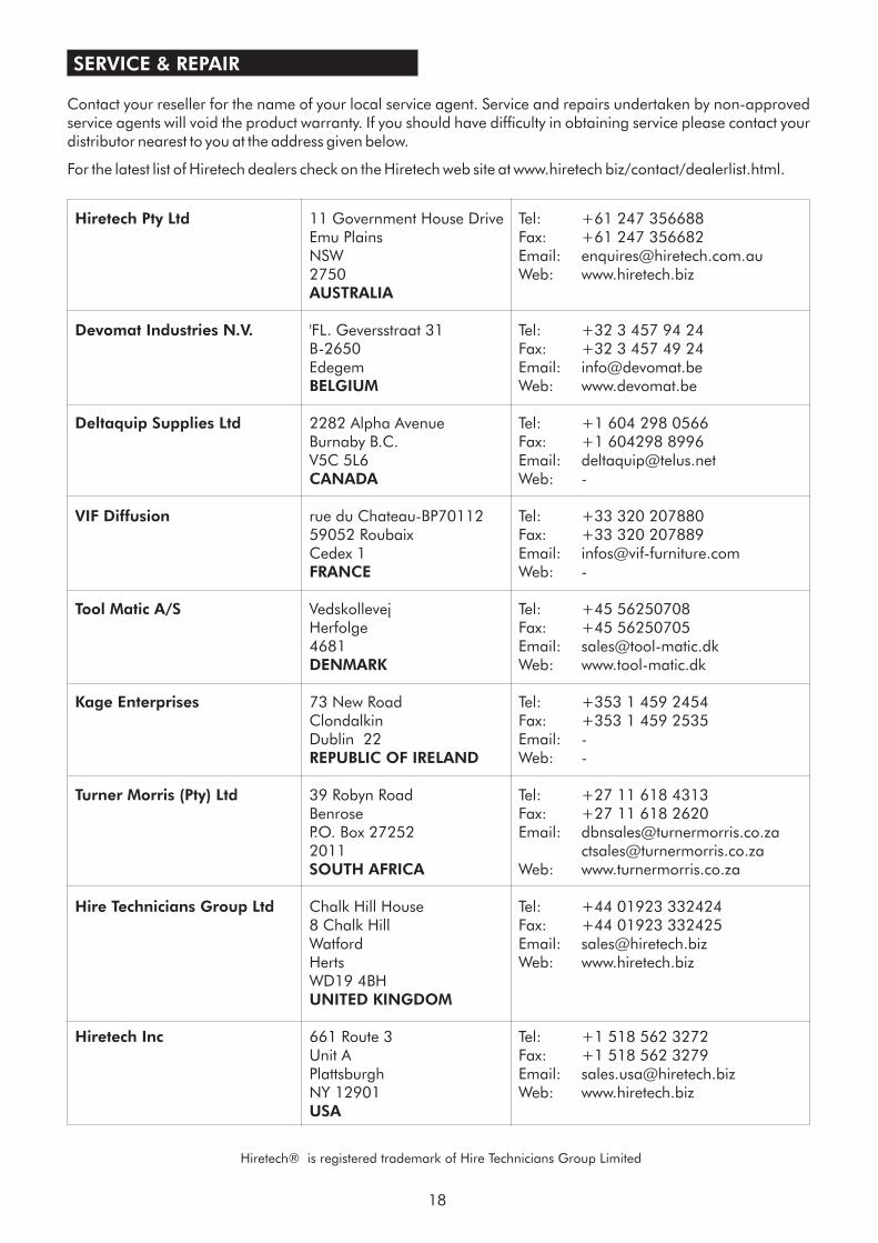
SERVICE & REPAIR
Contact your reseller for the name of your local service agent. Service and repairs undertaken by non-approvedservice agents will void the product warranty. If you should have difficulty in obtaining service please contact yourdistributor nearest to you at the address given below.
For the latest list of Hiretech dealers check on the Hiretech web site at www.hiretech biz/contact/dealerlist.html.
18
Hiretech® is registered trademark of Hire Technicians Group Limited
Hiretech Pty Ltd
AUSTRALIA
Devomat Industries N.V.
BELGIUM
Deltaquip Supplies Ltd
CANADA
VIF Diffusion
FRANCE
Tool Matic A/S
DENMARK
Kage Enterprises
REPUBLIC OF IRELAND
Turner Morris (Pty) Ltd
Hire Technicians Group Ltd
UNITED KINGDOM
Hiretech Inc
USA
11 Government House Drive Tel: +61 247 356688Emu Plains Fax: +61 247 356682NSW Email: [email protected] Web: www.hiretech.biz
'FL. Geversstraat 31 Tel: +32 3 457 94 24B-2650 Fax: +32 3 457 49 24Edegem Email: [email protected]
Web: www.devomat.be
2282 Alpha Avenue Tel: +1 604 298 0566Burnaby B.C. Fax: +1 604298 8996V5C 5L6 Email: [email protected]
Web: -
rue du Chateau-BP70112 Tel: +33 320 20788059052 Roubaix Fax: +33 320 207889Cedex 1 Email: [email protected]
Web: -
Vedskollevej Tel: +45 56250708Herfolge Fax: +45 562507054681 Email: [email protected]
Web: www.tool-matic.dk
73 New Road Tel: +353 1 459 2454Clondalkin Fax: +353 1 459 2535Dublin 22 Email: -
Web: -
39 Robyn Road Tel: +27 11 618 4313Benrose Fax: +27 11 618 2620P.O. Box 27252 Email: [email protected]
[email protected]: www.turnermorris.co.za
Chalk Hill House Tel: +44 01923 3324248 Chalk Hill Fax: +44 01923 332425Watford Email: [email protected] Web: www.hiretech.bizWD19 4BH
661 Route 3 Tel: +1 518 562 3272Unit A Fax: +1 518 562 3279Plattsburgh Email: [email protected] 12901 Web: www.hiretech.biz
2011SOUTH AFRICA

MANUFACTURED BY
HIRE TECHNICIANS GROUP LIMITEDCHALK HILL HOUSE, 8 CHALK HILL, WATFORD,
HERTS, WD19 4BH. UNITED KINGDOM
TEL: +44 (0)1923 332424 FAX: +44 (0)1923 332425E-mail: [email protected] Web: www.hiretech.biz
HIRETECH LIMITED WARRANTY®
Hiretech warrants to the original purchaser that the Hiretech machine covered by this warranty is freefrom defects in workmanship and materials. Should any part fail in the period of two years from the dateof the original purchase as a result of a defect, Hiretech will (at it’s option) either repair or replace thepart without charge provided that the machine has been operated in accordance with the OwnersManual and Operating Instructions.
Should any such defect arise, please contact your nearest authorised repair agent. Standard serviceover land mainland freight costs will be refunded on warranty repairs at the sole discretion of Hiretech orthe authorised repair agent. If the repair is non-warranty, the customer will be advised before any workis undertaken.
This warranty is the sole warranty by Hiretech and is in lieu of all other warranties express or impliedand releases Hiretech from all other obligations and liabilities.
This warranty does not apply to normal wear and tear to the machine, and in particular does not covernormal wear parts such as mains cable, wheels, switches, relays, brushes, rubber parts, hoses andbearings. This warranty also does not cover, and Hiretech will not be liable for, excessive wear causedby abnormal use.
Hiretech will under no circumstances be liable for alterations to the machine or for damage caused bythird persons, or for misuse or abuse of the machine, or damage caused during transportation. Repairsof the machine made or attempted by persons other than those specifically authorised by Hiretech shallrender this warranty void and Hiretech will not be liable for such repairs, the cost of such repairs, or theconsequences of such repairs. Where spare parts are used on the machine and they do not conform toHiretech specifications, this warranty will be rendered void and Hiretech will not be liable.
Hiretech will not be liable for any indirect or consequential loss, damage, cost or expense of any kindwhatever and however caused whether arising under contract, tort (including negligence) or otherwiseincluding (without limitation) loss of production, loss of profits or contracts or of operating time orgoodwill or anticipated savings.
® ®
®
®
®
®
®
®
®
® ®
®