Embed Size (px)
Citation preview

Save These Instructions
Orbital Floor SanderModel SD150
X8800
OPERATING INSTRUCTIONS
COMMERCIAL ORBITAL SANDER
CONGRATULATIONSYOU HAVE JUST ACQUIRED A HIGH QUALITY SANDER.PLEASE READ THIS MANUAL CAREFULLY BEFOREOPERATING YOUR NEW SANDER. KEEP MANUAL ONHAND FOR FURTHER REFERENCES.
TECHNICAL MACHINE SPECIFICATIONS
AC motor 115V/60 Hz.Motor power 1.5 HP, 3,460 RPM
Current Off load 6 A On load 12 A (average) Startup 15A
Vacuum motor 115V/60 Hz - 230W.Abrasive 15fl" (400 mm) x 4fi" (115 mm)
Machine weight 133 lbs. (60 kg)
2
CONTENTS
Safety Instructions ...................................................3
Important Parts of the Machine ..............................4
Machine Set-up
Setting up the dust bag . . . . . . . . . . . . . . . . . . . . . . . . . . . . . . . . . . . . . . . . . . . . . . . . . . .5
Setting up the handle support . . . . . . . . . . . . . . . . . . . . . . . . . . . . . . . . . . . . . . . . . . .5
Fitting the sandpaper . . . . . . . . . . . . . . . . . . . . . . . . . . . . . . . . . . . . . . . . . . . . . . . . . . . . . .5
How to Start the Machine
Setting up and leveling the sanding plate . . . . . . . . . . . . . . . . . . . . . . . . . . . .6
Connection to power supply . . . . . . . . . . . . . . . . . . . . . . . . . . . . . . . . . . . . . . . . . . . . .7
Starting the machine . . . . . . . . . . . . . . . . . . . . . . . . . . . . . . . . . . . . . . . . . . . . . . . . . . . . . . .7
How to Operate the Machine ...................................7
Maintenance
Replacement of the wheels . . . . . . . . . . . . . . . . . . . . . . . . . . . . . . . . . . . . . . . . . . . . . .7
Replacement of the lamp . . . . . . . . . . . . . . . . . . . . . . . . . . . . . . . . . . . . . . . . . . . . . . . . .8
Dust suction . . . . . . . . . . . . . . . . . . . . . . . . . . . . . . . . . . . . . . . . . . . . . . . . . . . . . . . . . . . . . . . . . .8
Accessories ................................................................9
Assembly Drawing and Spare Parts List ...............10
CAUTION
Read all instructions, warnings and cau-tions before using!
These guidelines are provided for yourprotection and convenience. Please readthem carefully. If you have any questionsregarding the use of your equipment callPowr-Flite Technical Service at800.880.2913. The manual containsimportant information for the use of thismachine and safety instructions for pre-venting personal injuries, damage to themachine or to other property. Failure toadhere to instructions provided can poten-tially void any warranties.
INTRODUCTION
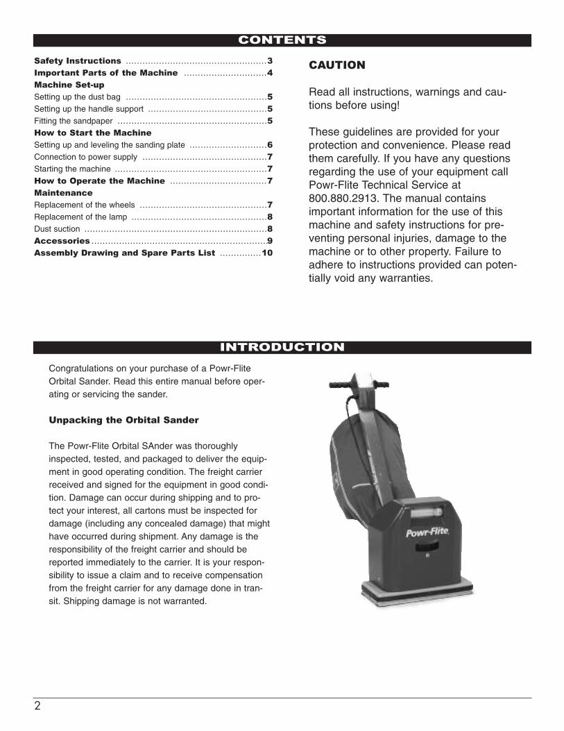
Congratulations on your purchase of a Powr-FliteOrbital Sander. Read this entire manual before oper-ating or servicing the sander.
Unpacking the Orbital Sander
The Powr-Flite Orbital SAnder was thoroughlyinspected, tested, and packaged to deliver the equip-ment in good operating condition. The freight carrierreceived and signed for the equipment in good condi-tion. Damage can occur during shipping and to pro-tect your interest, all cartons must be inspected fordamage (including any concealed damage) that mighthave occurred during shipment. Any damage is theresponsibility of the freight carrier and should bereported immediately to the carrier. It is your respon-sibility to issue a claim and to receive compensationfrom the freight carrier for any damage done in tran-sit. Shipping damage is not warranted.

3
S A F E T Y I N S T R U C T I O N S
• Operators must be trained to operate this machineand must read and understand this manual com-pletely before operating the equipment.
• Machines can cause flammable materials andvapors to burn. Do not use the machine with ornear solvents, thinners, fuels, or other flammablematerials.
• To prevent the risk of fire or explosion:
a) Empty the dustbag when it is 1/3 full.
b) Empty the dustbag when the work is over. Donot leave contents in the dust bag.
c) Do not put the contents of the dust bag into afire or furnace.
d) Use a hammer and punch to countersink allnails against the floor so that the sanding drumwill not touch them and create sparks whichmight cause a fire in the dust bag.
• Do not use the machine if it is not completelyassembled.
• To prevent personal injury, always disconnect thepower supply before changing the sandpaper, emp-tying the dust bag, leaving it unattended or attempt-ing any maintenance or service of the machine.
• To prevent electrocution, avoid contact with ground-ed devices, i.e. electric stoves, radiators, refrigera-tors, etc.
• Do not expose the machine to rain.• Keep the electrical parts dry. The machine should
be stored in a dry place.
• When you operate the machine, make sure thatthe power cord is free from under the sandingplate.
• Check the cord and plugs and replace them ifdamaged. Do not use the machine if the cord isdamaged. Keep the cord away from heat, oil andwater.
• Always use a 3-wire electrical cord (GA 14-3) andconnect the machine to grounded plugs.
• Make sure that the switch is in the “0” - “Off” posi-tion before connecting the machine to the powersupply.
• Be careful not to accidentally start the machine,make sure that your hands are empty when youpress the switch.
• Always use a dust mask. if the sanding operationis dusty.
• Do not operate the machine when you are tired,avoid positions which can cause fatigue. Keepproper footing and balance at all times.
• Always keep the machine clean. Check it for dam-aged parts before use, change damaged movingparts and always follow maintenance instructions.
• Keep children away from the machine.
Read these instructions carefully before operating or attempting tocarry out any service or maintenance procedure on the machine.To reduce the risk of fire, electric shock and personal injury when usingelectrical tools, the following basic safety precautions should always betaken.

4
Fig. 1
Fig. 2
Fig. 3
Fig. 4
IMPORTANT PARTS OF THE MACHINE
The double-bladed switch is located in the condenserbox beside the motor.
When the switch is pushed to the left the motor is off. The motor starts when the switch is pressed to the right.
Suction system
This is fitted with a suction tube operated by a 230Wpower motor which suctions dust through a flexiblehose when the machine is working.
Lamp
Sanding plate holder
The PL-9 W type lamp is directly connected to thepower supply. This means that the light comes onautomatically when the machine is started.
This is located underneath the machine and is fittedwith 2 pins that secure the sanding plate.
Switch

5
1 Loosen the lever.2 Push the handle tube in as far as possible.3 Adjust the lever.
1 Sandpaper with an adhesive backing.Place the sandpaper on the plate support (Fig. 7).
Fig. 5
Fig. 6
Fig. 7
Fig. 8
MACHINE SET-UP
Dust bag
Setting up the handle
The dust bag must be placed at the suction tube out-let and hung from the machine handle.
2 Sandpaper with a paper backing.
Cut to the appropriate length and hold both endsfirmly with the sandpaper holder to prevent thesandpaper from slipping during operation (Fig. 8).
Fitting the sandpaper

6
Fig. 9
Fig. 10
Fig. 11
Setting-up and leveling the sanding plate
1 Disconnect the sander from the power supply.
2 Place the machine in the position shown in (Fig. 9.)
4 To level the height of the caster wheels in relationto the sanding plate, unloosen both screws andturn the eccentric shaft wheels: the wheels will goup and down (Fig. 11).
5 The wheels must reach the plate height.
3 Fit the sanding plate by matching up the two plateholes with the two hooking pins (Fig. 10).
HOW TO START THE MACHINE

7
Fig. 12
Fig. 13
Fig. 14
The sander must be connected to a 115V/60 Hz powersupply with grounded plugs.
CAUTION!
To prevent electrocution keep the machine in a dry place.Do not expose the machine to rain.
Use 3-wire (GA 14-3) power cords connected to groundedplugs.
The machine cord, extension cords and connection plugsmust be in perfect condition.
1 Before connecting the cord to the power supply, makesure that the switch is in the “O” position.
2 After placing the sander as shown in Fig. 12, push theswitch down with one hand and hold the machine withthe other.
3 Do not press on the sander. Its own weight is sufficientfor achieving efficient work.
MAINTENANCE
How to start the machine
How to operate the machine
The sander is usually held by the handle with both handsand rolled along to the places to be sanded. Move themachine to avoid marks on the floor. If the floor is notlevel, use the support plate for the mesh sandpaper, asshown in (Fig. 13.)
Connection to power supply
Replacement of the wheels
1 Disconnect the machine from the power supply.
2 Unloosen and remove both screws from the wheelshaft bracket.
3 Remove the wheels beside the shaft.
4 Remove the shaft wheels with an hexagonal wrenchandreplace them.
HOW TO START THE MACHINE

8
Replacement of the lamp
The machine has a light fitted with a PL-9W lamp.
To replace it:
1 Remove the front plastic part by gently pressingon its sides (Fig. 15).
2 Replace the lamp with a new one (Fig. 16).
Fig.17
Dust suction
The machine is equipped with a dustbag.
For optimum vacuum performance:
1 The caster wheels should be level with the sand-ing plate.
2 Empty the dustbag when it is 1/4 full. Suctionbecomes less effective when the bag gets too full.
3 Do not use the machine with more than one sheetof sandpaper on the plate.
4 The bag is made with a special material which letsair get through it, but not dust.
5 Change the dustbag several times a year, even ifit is not torn; the ageing of material due to dustaccumulation will obstruct the circulation of air andtherefore cause faulty suction.
Accessories
Included with the machine:
2 sanding plates (one is already fitted on the sander).1 dust bag.Screen & white pad.3-wire electrical cord (GA 14-3).
ACCESSORIES
Fig.18
Fig.15
Fig.16

9
ASSEMBLY DRAWING AND SPARE PARTS LIST
ref# part # desc1.1 SD129 CAPACITOR USA 100 MF1.4 SD130 CABLE WITH PLUG USA8 SD131 SPLIT PIN ø 1,5 x 1214 SD132 SPRING 10 SD133 SCREW DIN 913 M 6 x 5 16 SD134 SHAFT17 SD135 PRESSIONING SCREW M 10 26 SD136 HOUSING27 SD137 BUMPER29 SD138 SANDPAPER SUPPORT31 SD139 BUSHING32 SD140 SANDPAPER PLATE34 SD141 RUBBER36 SD142 DUST BRUSH (SHORT)
ref# part # desc37 SD143 DUST BRUSH 39.2 SD144 LAMP 9W 115V/60Hz53 SD145 HANDLE ACCESS M 854 SD146 WASHER DIN 125 M 1059 SD147 PROFIL BRACKET62 SD148 WHEEL ø 8068 SD149 SCREW DIN 931 M 8 x 13082 SD151 FAN HOUSING79 SD152 VACUUM MOTOR USA
SD153 DUST BAGSD154 PLATE WITH WING NUTS COMPLETE SD155 PLATE WITH FOAM COMPLETE SD156 VELCRO 115/400

10
ASSEMBLY DRAWING AND SPARE PARTS LIST

11
DECLARATlON OF CONFORMlTY
QUIDE, S.A. declare under our responsibility that the floor sanding machine model ORBI meets the requires stan-dards of safety and health with respect to the design and manufacture of machinery, according to the below men-tioned regulations.
EEC regulations regarding to:
Machines (89/392/EEC)Low voltage (73/23/EEC)Electromagnetic compatibility (89/336 EEC)(Last changed through 93/68/EEC from 22.7.1993.)
In conformity with the following standards:
EN 292 Part 1 and Part 2 (Safety of machinery, equipment and sys-tems)EN 60204.1 (Electrical equipment of industrial machines)
DECLARATION OF CONFORMITY

WARRANTY
Powr-Flite warrants new products manufactured and sold under the name of Powr-Flite to be free fromdefects in materials and workmanship under normal use and service, provided such goods are installed,operated and maintained in accordance with written manuals or other instructions for a period of 1-year.Powr-Flite’s obligation under this warranty is limited to repairing or replacing, at our option, such productsor parts which are returned to our factory authorized service center, within the warranty period and arefound to be defective in materials or workmanship. This warranty does not apply to excessive wear causedby abnormal use, nor does it apply to normal wear parts such as main cable, wheels, switches, relays,brushes, rubber parts, hoses and bearings.
This warranty is in lieu of all other warranties expressed or implied, and releases Powr-Flite from all otherobligations and liabilities.
Powr-Flite assumes no responsibility for repairs, and the cost of such repairs, made or attempted by per-sons other than those specifically authorized by Powr-Flite. Any such unauthorized repairs shall void thiswarranty.
WARRANTY
A Tacony CompanyFt. Worth, TX 76140
1-800-880-2913