Embed Size (px)
Citation preview
Disc Sander Angle Jig Instructions
Congratulations on the purchase of your new Disc Sander Angle Jig! It allows you to sand precise angles on the end of your workpiece and to sand perfectly round circles. For safe and effective operation of the jig, please read the instructions fully before starting.

2
> For any tool that is used in conjunction with this product always read, understand and follow the instructions and safety warnings for that tool.
> Before using this product, review and verify that all tools used with it are in proper working order as definedbythetool’sowner’smanual.
>Allsafetyequipmentmustbeinstalledandworking properlyasdefinedbythetool’sowner’smanual.
> Do not use this product until you have read the provided instructions and warnings and are confident youunderstandthem.
>AlwayswearsafetyglassesincompliancewithANSI safety standards and hearing protection and follow all standard shop safety practices including: • Keep your work area well lit and clean. • Usedustcollectiontoolsanddustfacemasksto reduce exposure to dust. • Useaccessorysafetyequipmentsuchas feather boards, push sticks, and push blocks whenever appropriate. • Do not use power tools in explosive environments,e.g.inthepresenceofflammable liquids,fumesordust. • Keep children and bystanders away while operating your tools. • Maintainproperfootingatalltimesanddo not overreach. • Do not force the tool. • Unplugallpowertoolsbeforemakingany adjustmentsorchangingaccessories.
>Remainalertandusegoodjudgmentwhenusing this tool. Do not use this tool if you are in any way impairedbymedications,alcohol,drugsorfatigue.
>Dressappropriatelyandremovealljewelry,secure loose clothing and tie up long hair before using this tool.
> Itisthesoleresponsibilityofthepurchaserofthistool to ensure that any third party reads and agrees to all thesafetyprecautionsoutlinedinthismanualprior to using the tool.
> Maintain these instructions and warnings as long as you own the tool. Keep in a place where they will be readily available for reference.
>Theuserassumesallriskfortheproperuseof this tool and for ensuring product suitability for intended application.
> These warnings and instructions do not represent the totalofallinformationavailableregardingtoolsafety, use and technique. Always seek out opportunities to learnmoreandimproveyourskillsandknowledge.
Thistoolisdesignedforspecificapplicationsasdefinedintheinstructionsandshouldnotbemodifiedand/orusedforanyotherapplications.BeforeusingtheDiscSanderAngleJigread,understandandfollowallinstructionsandsafetyinformationprovided.KEEP THESE INSTRUCTIONS.
GENERAL SAFETY WARNINGS
SPECIFIC SAFETY WARNINGS
>Theboltoftheexpandablemiterbarmustbe tightened to secure the jig before turning on the disc sander.
> When sanding with the jig fence as a support, the fencemustbesecuredbytighteningallknobs.
>Alwayskeepyourfingersawayfromthesandingdisc.
>Allsandingmustbedoneonthedownward-moving quadrant of the disc.
3
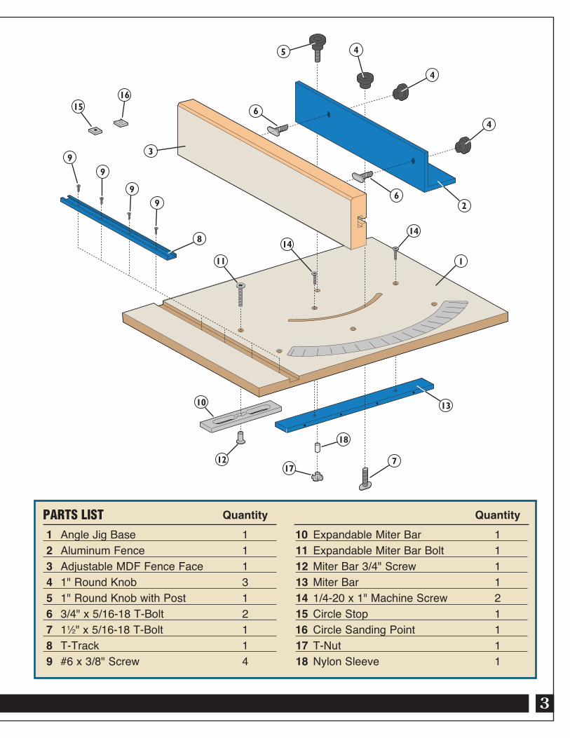
Quantity 1 AngleJigBase 1 2 AluminumFence 1 3 AdjustableMDFFenceFace 1 4 1"RoundKnob 3 5 1"RoundKnobwithPost 1 6 3/4"x5/16-18T-Bolt 2 7 11⁄2"x5/16-18T-Bolt 1 8 T-Track 1 9 #6x3/8"Screw 4
PARTS LIST Quantity10 ExpandableMiterBar 1 11 ExpandableMiterBarBolt 1 12MiterBar3/4"Screw 1 13MiterBar 1 14 1/4-20x1"MachineScrew 2 15 CircleStop 116 CircleSandingPoint 1 17 T-Nut 1 18 NylonSleeve 1
1615
9
9
9
9
11
1414
1
10
12
18
7
13
26
3
6
5 4
4
4
8
17
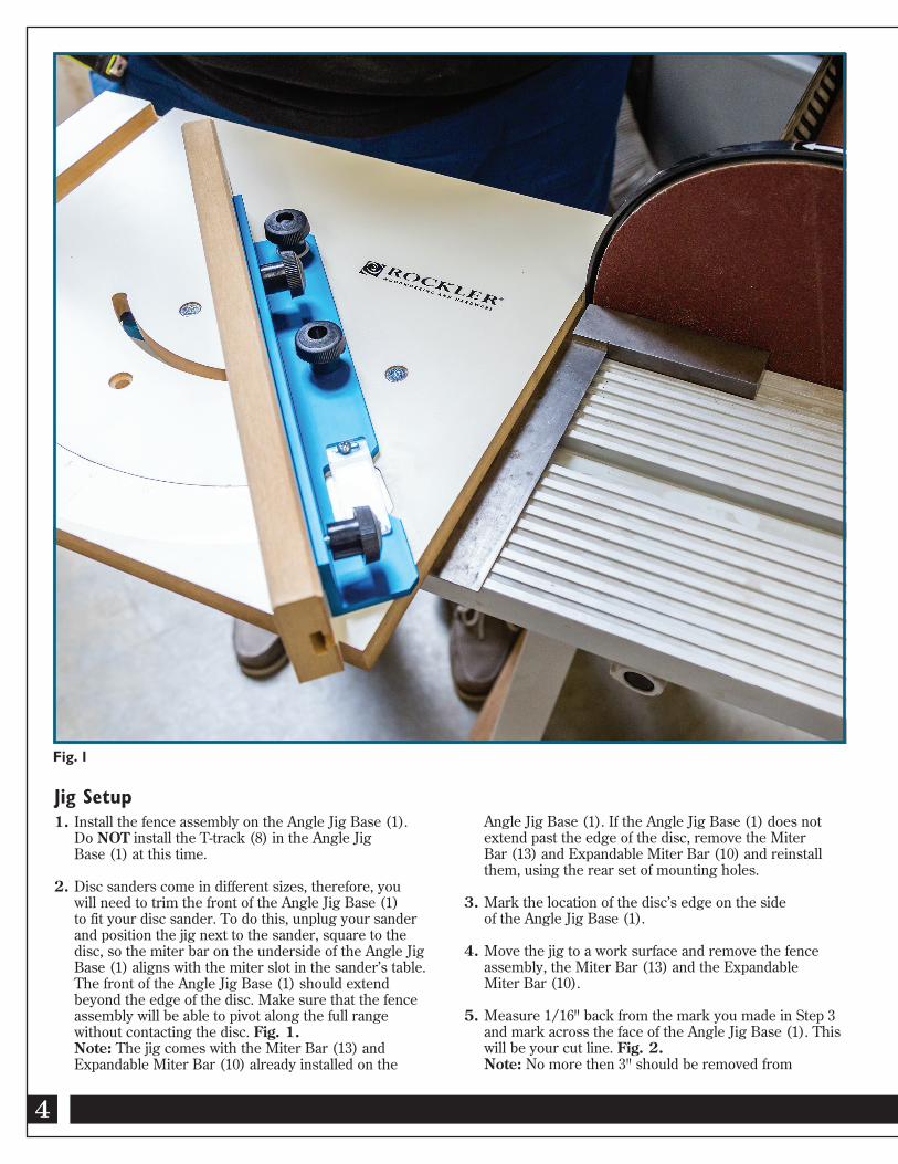
Angle Jig Base (1). If the Angle Jig Base (1) does not extend past the edge of the disc, remove the Miter Bar (13) and Expandable Miter Bar (10) and reinstall them, using the rear set of mounting holes.
3. Mark the location of the disc’s edge on the side of the Angle Jig Base (1).
4. Move the jig to a work surface and remove the fence assembly, the Miter Bar (13) and the Expandable Miter Bar (10).
5. Measure 1/16" back from the mark you made in Step 3 and mark across the face of the Angle Jig Base (1). This will be your cut line. Fig. 2. Note: No more then 3" should be removed from
Jig Setup1. Install the fence assembly on the Angle Jig Base (1). Do NOT install the T-track (8) in the Angle Jig Base (1) at this time.
2. Disc sanders come in different sizes, therefore, you will need to trim the front of the Angle Jig Base (1) to fit your disc sander. To do this, unplug your sander and position the jig next to the sander, square to the disc, so the miter bar on the underside of the Angle Jig Base (1) aligns with the miter slot in the sander’s table. The front of the Angle Jig Base (1) should extend beyond the edge of the disc. Make sure that the fence assembly will be able to pivot along the full range without contacting the disc. Fig. 1. Note: The jig comes with the Miter Bar (13) and Expandable Miter Bar (10) already installed on the
Fig. 1
4
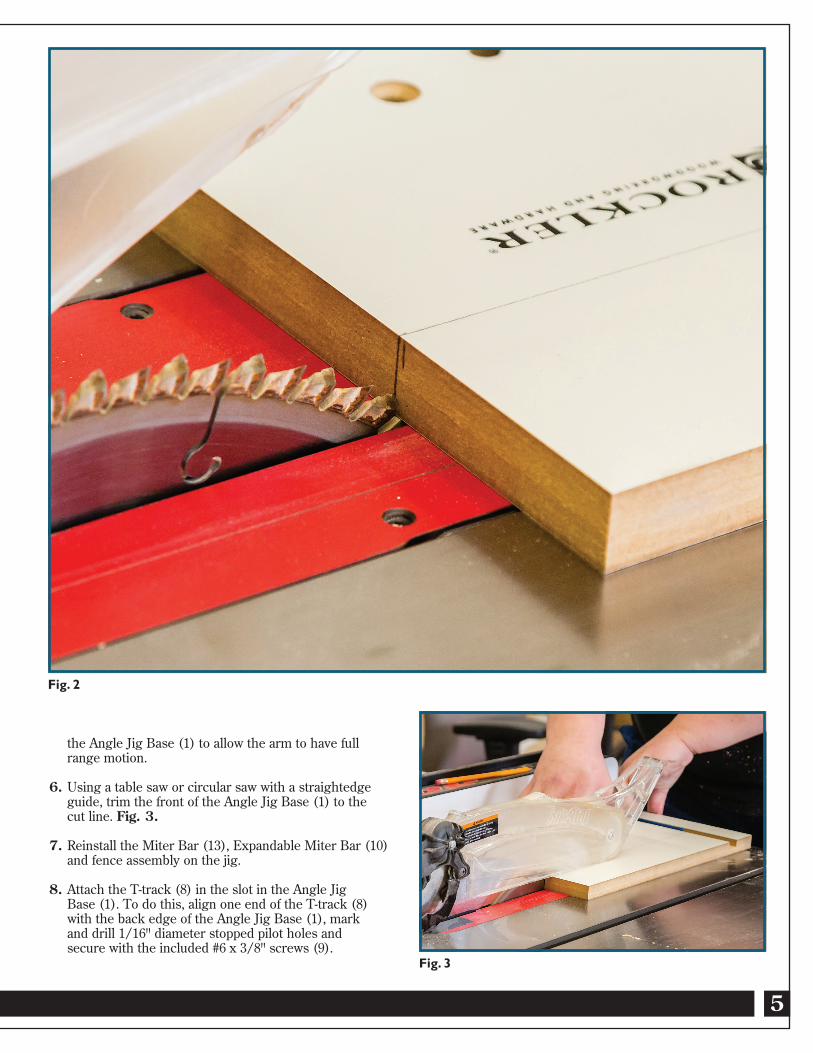
the Angle Jig Base (1) to allow the arm to have full range motion.
6. Using a table saw or circular saw with a straightedge guide, trim the front of the Angle Jig Base (1) to the cut line. Fig. 3.
7. Reinstall the Miter Bar (13), Expandable Miter Bar (10) and fence assembly on the jig.
8. Attach the T-track (8) in the slot in the Angle Jig Base (1). To do this, align one end of the T-track (8) with the back edge of the Angle Jig Base (1), mark and drill 1/16" diameter stopped pilot holes and secure with the included #6 x 3/8" screws (9).
5
Fig. 2
Fig. 3
6
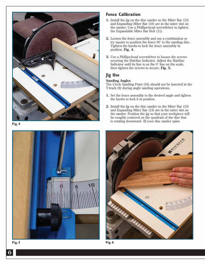
Fence Calibration1. Install the jig on the disc sander so the Miter Bar (13) and Expanding Miter Bar (10) are in the miter slot on the sander. Use a Phillips-head screwdriver to tighten the Expandable Miter Bar Bolt (11).
2. Loosen the fence assembly and use a combination or try square to position the fence 90˚ to the sanding disc. Tighten the knobs to lock the fence assembly in position. Fig. 4.
3. Use a Phillips-head screwdriver to loosen the screws securing the Hairline Indicator. Adjust the Hairline Indicator until its line is on the 0˚ line on the scale, then tighten the screws to secure. Fig. 5.
Jig UseSanding AnglesThe Circle Sanding Point (16) should not be inserted in the T-track (8) during angle sanding operations.
1. Set the fence assembly to the desired angle and tighten the knobs to lock it in position.
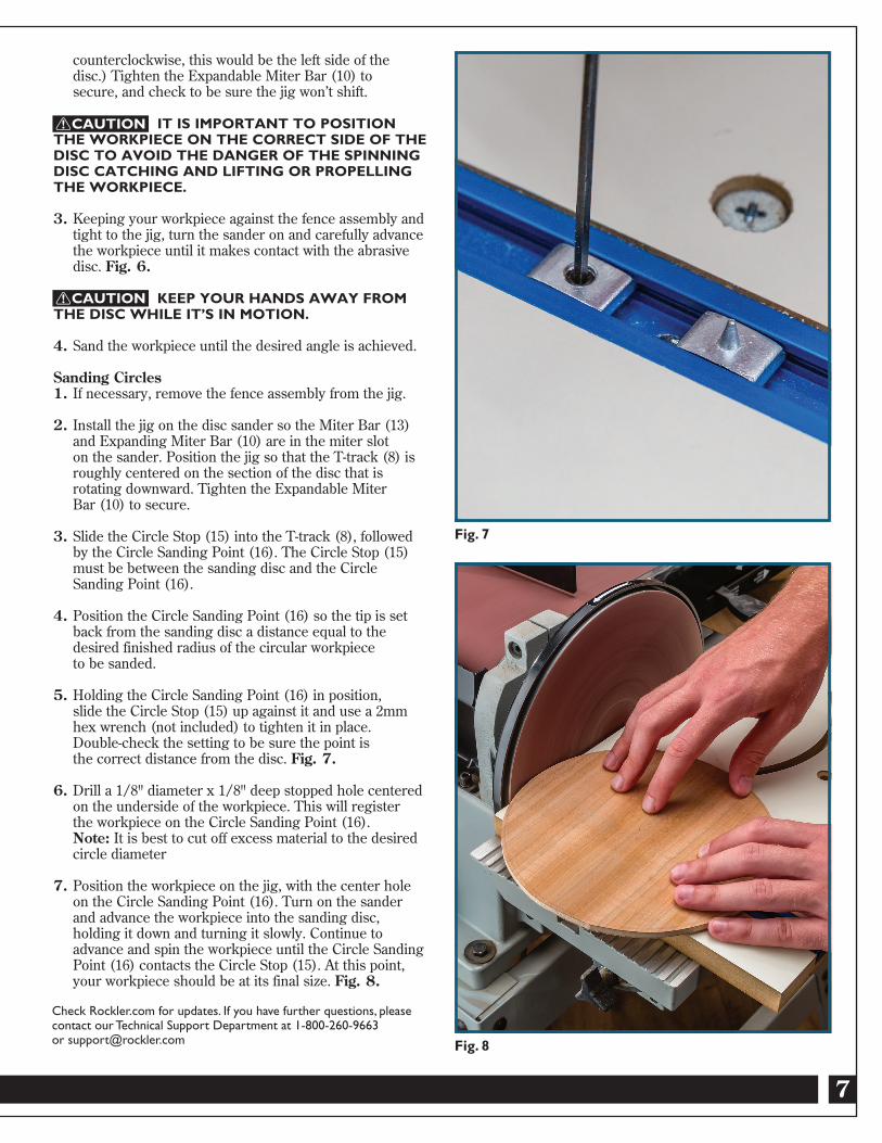
2. Install the jig on the disc sander so the Miter Bar (13) and Expanding Miter Bar (13) are in the miter slot on the sander. Position the jig so that your workpiece will be roughly centered on the quadrant of the disc that is rotating downward. (If your disc sander spins
Fig. 5
Fig. 4
Fig. 6
7
counterclockwise, this would be the left side of the disc.) Tighten the Expandable Miter Bar (10) to secure, and check to be sure the jig won’t shift.
IT IS IMPORTANT TO POSITION THE WORKPIECE ON THE CORRECT SIDE OF THE DISC TO AVOID THE DANGER OF THE SPINNING DISC CATCHING AND LIFTING OR PROPELLING THE WORKPIECE.
3. Keeping your workpiece against the fence assembly and tight to the jig, turn the sander on and carefully advance the workpiece until it makes contact with the abrasive disc. Fig. 6.
KEEP YOUR HANDS AWAY FROM THE DISC WHILE IT’S IN MOTION.
4. Sand the workpiece until the desired angle is achieved.
Sanding Circles1. If necessary, remove the fence assembly from the jig.
2. Install the jig on the disc sander so the Miter Bar (13) and Expanding Miter Bar (10) are in the miter slot on the sander. Position the jig so that the T-track (8) is roughly centered on the section of the disc that is rotating downward. Tighten the Expandable Miter Bar (10) to secure.
3. Slide the Circle Stop (15) into the T-track (8), followed by the Circle Sanding Point (16). The Circle Stop (15) must be between the sanding disc and the Circle Sanding Point (16).
4. Position the Circle Sanding Point (16) so the tip is set back from the sanding disc a distance equal to the desired finished radius of the circular workpiece to be sanded.
5. Holding the Circle Sanding Point (16) in position, slide the Circle Stop (15) up against it and use a 2mm hex wrench (not included) to tighten it in place. Double-check the setting to be sure the point is the correct distance from the disc. Fig. 7.
6. Drill a 1/8" diameter x 1/8" deep stopped hole centered on the underside of the workpiece. This will register the workpiece on the Circle Sanding Point (16). Note: It is best to cut off excess material to the desired circle diameter
7. Position the workpiece on the jig, with the center hole on the Circle Sanding Point (16). Turn on the sander and advance the workpiece into the sanding disc, holding it down and turning it slowly. Continue to advance and spin the workpiece until the Circle Sanding Point (16) contacts the Circle Stop (15). At this point, your workpiece should be at its final size. Fig. 8.
Fig. 8
Fig. 7
Check Rockler.com for updates. If you have further questions, pleasecontact our Technical Support Department at 1-800-260-9663 or [email protected]
CAUTION
CAUTION

Distributed by Rockler Companies, Inc. ©2016 Rockler Woodworking and Hardware
54963Rev 08/16