Embed Size (px)
Citation preview

Flip Flop
www.ustudy.in
Introduction
• A flip-flop is a semiconductor device that
has a digital output which can be toggled
between two stable states by providing it
with the appropriate digital input signals.
www.ustudy.in
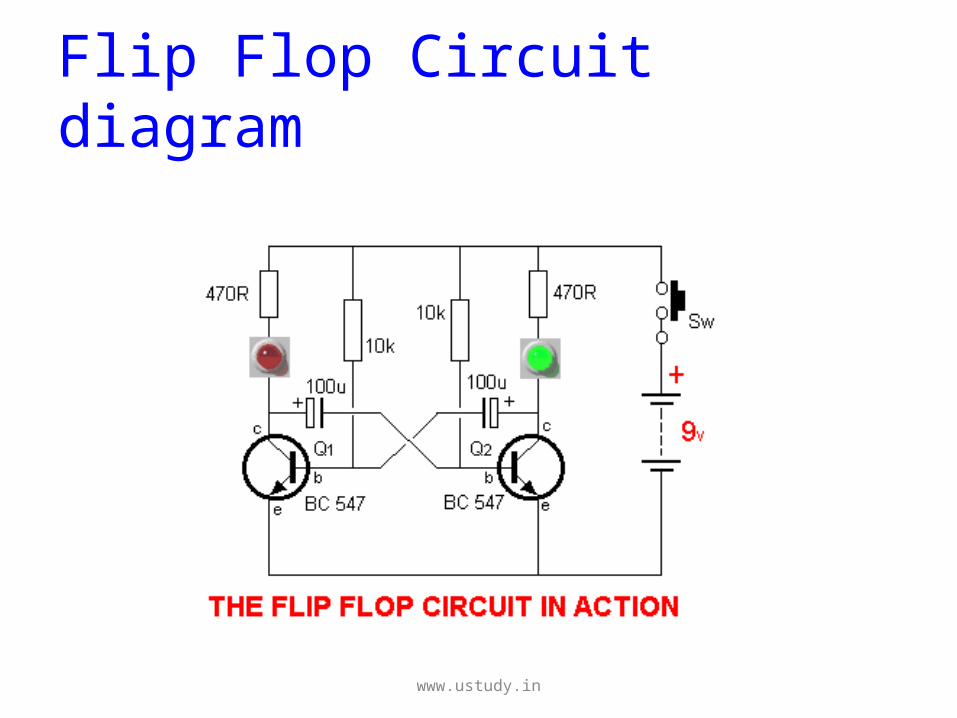
Flip Flop Circuit diagram
www.ustudy.in
Flip-Flopping
• Once the output is put in one state, it
remains there until a change in the inputs
causes it to toggle again.
• This toggling between two logic states is
also referred to as 'flip-flopping'
www.ustudy.in
Types of Flip flop
• RS Flip-flop
• D Flip-flop
• T Flip-flop
• JK Flip-flop
• Master Slave Flip-flop
• Edge Triggered Flip-flop
www.ustudy.in
RS Flip Flop
• SR flip-flop (Or "RS flip-flop") A
"set/reset" flip-flop in which activating the
"S" input will switch it to one stable state
and activating the "R" input will switch it
to the other state.
www.ustudy.in
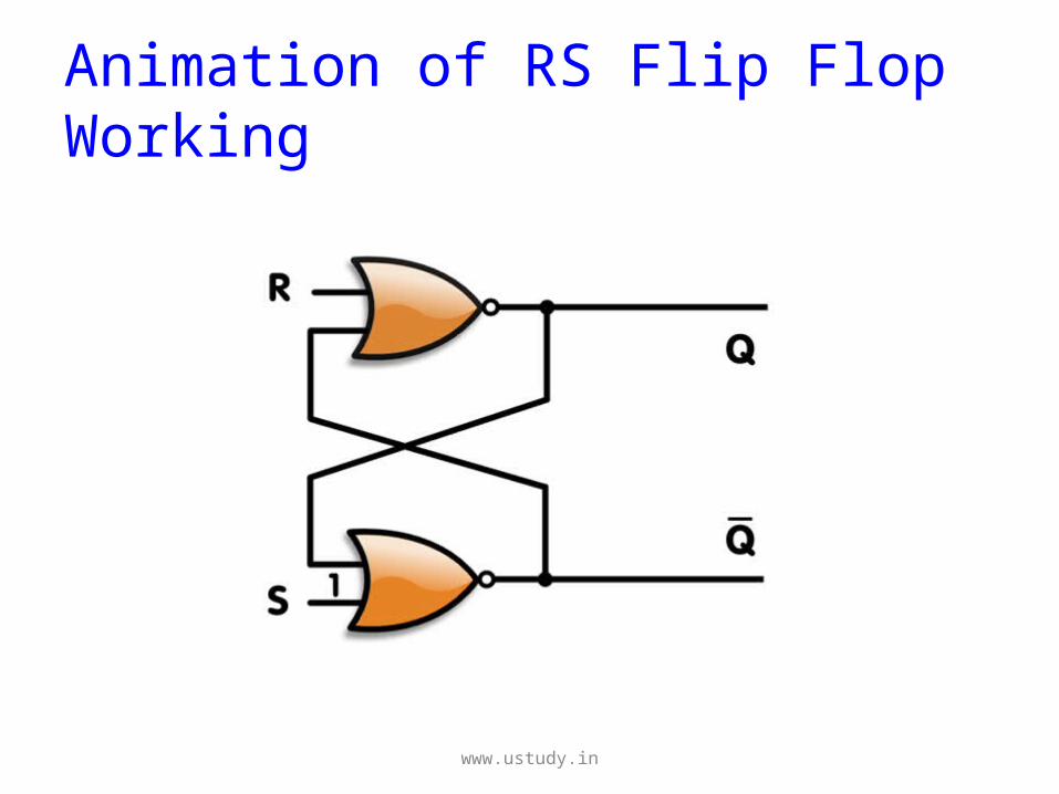
Animation of RS Flip Flop Working
www.ustudy.in
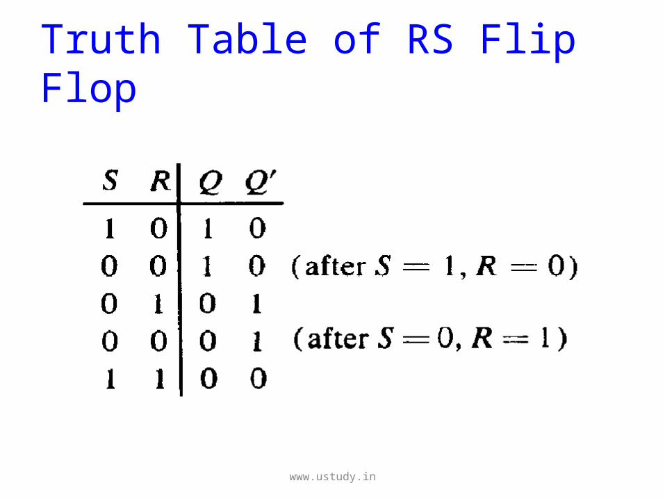
Truth Table of RS Flip Flop
www.ustudy.in
Working of RS Flip Flop
• The outputs of a basic SR flip-
flop change whenever its R or S inputs
change appropriately. A clocked SR flip-
flop has an extra clock input which
enables or disables the other two inputs.
www.ustudy.in
Cont.,
• When they are disabled the outputs remain
constant.
• If we connect two clocked SR flip-flops so that the
Q and /Q outputs of the first, "master" flip-flop
drive the S and R inputs of the second, "slave"
flip-flop, and we drive the slave's clock input with
an inverted version of the master's clock, then we
have an edge-triggered RS flip-flop.
www.ustudy.in
Cont.,
• The external R and S inputs of this device are
latched on one edge (transition) of the clock
(e.g. the falling edge) and the outputs will only
change on the next opposite (rising) edge.
• If both R and S inputs are active (when
enabled), a race condition occurs and the
outputs will be in an indeterminate state.
www.ustudy.in
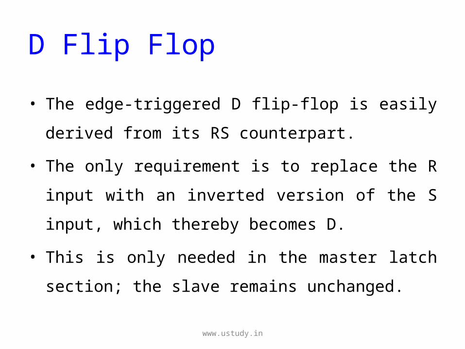
D Flip Flop
• The edge-triggered D flip-flop is easily derived
from its RS counterpart.
• The only requirement is to replace the R input
with an inverted version of the S input, which
thereby becomes D.
• This is only needed in the master latch section;
the slave remains unchanged.
www.ustudy.in
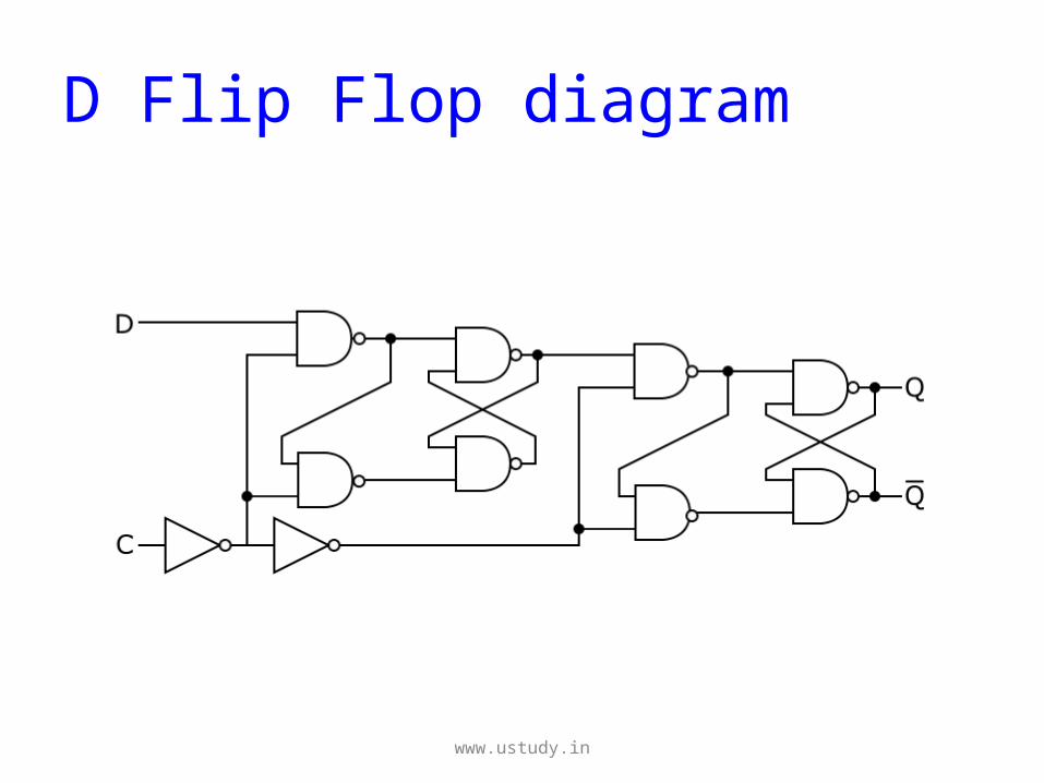
D Flip Flop diagram
www.ustudy.in
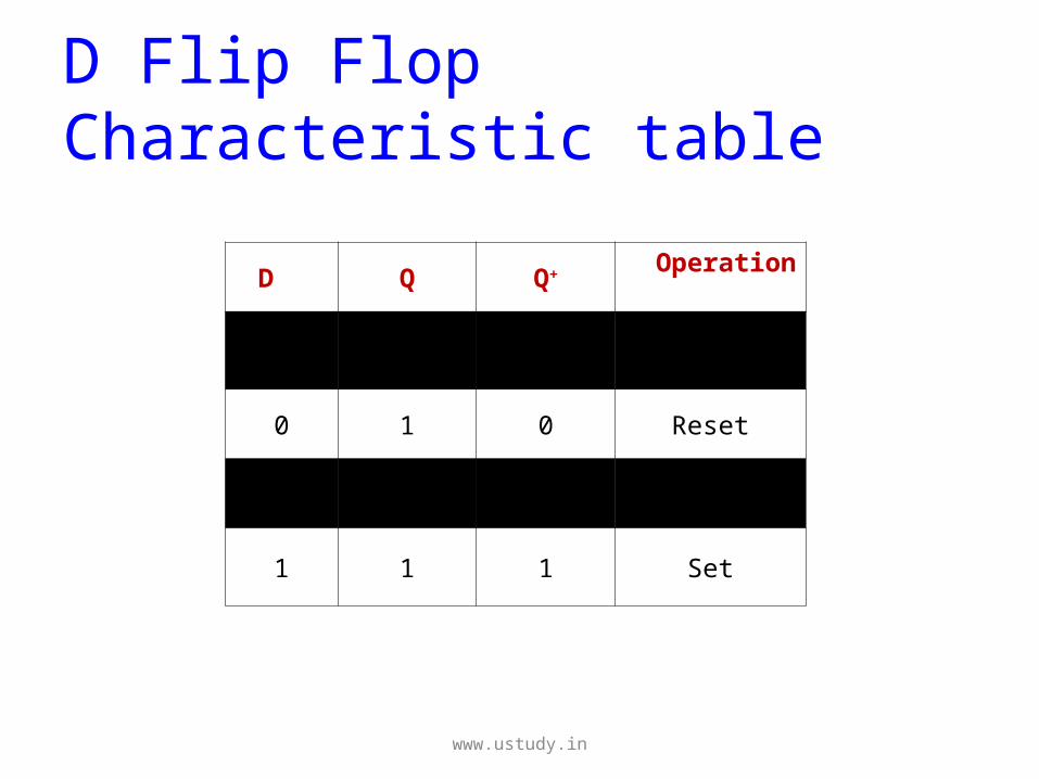
D Flip Flop Characteristic table
D Q Q+ Operation
0 0 0 Reset
0 1 0 Reset
1 0 1 Set
1 1 1 Set
www.ustudy.in
Working of a D Flip Flop
• One essential point about the D flip-flop is that
when the clock input falls to logic 0 and the
outputs can change state, the Q output always
takes on the state of the D input at the moment
of the clock edge.
• This was not true of the RS and JK flip-flops.
www.ustudy.in
Cont.,
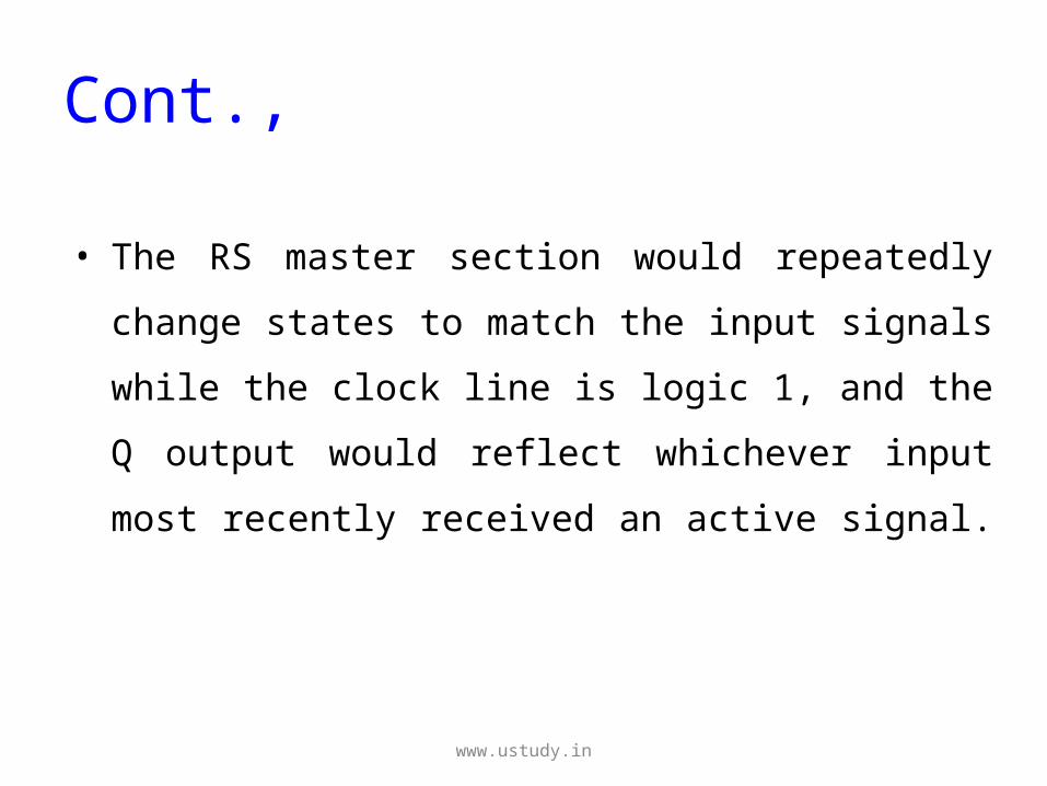
• The RS master section would repeatedly
change states to match the input signals while
the clock line is logic 1, and the Q output
would reflect whichever input most recently
received an active signal.
www.ustudy.in
Cont.,
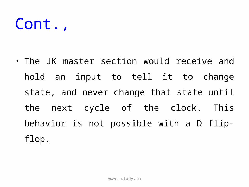
• The JK master section would receive and hold
an input to tell it to change state, and never
change that state until the next cycle of the
clock. This behavior is not possible with a D
flip-flop.
www.ustudy.in
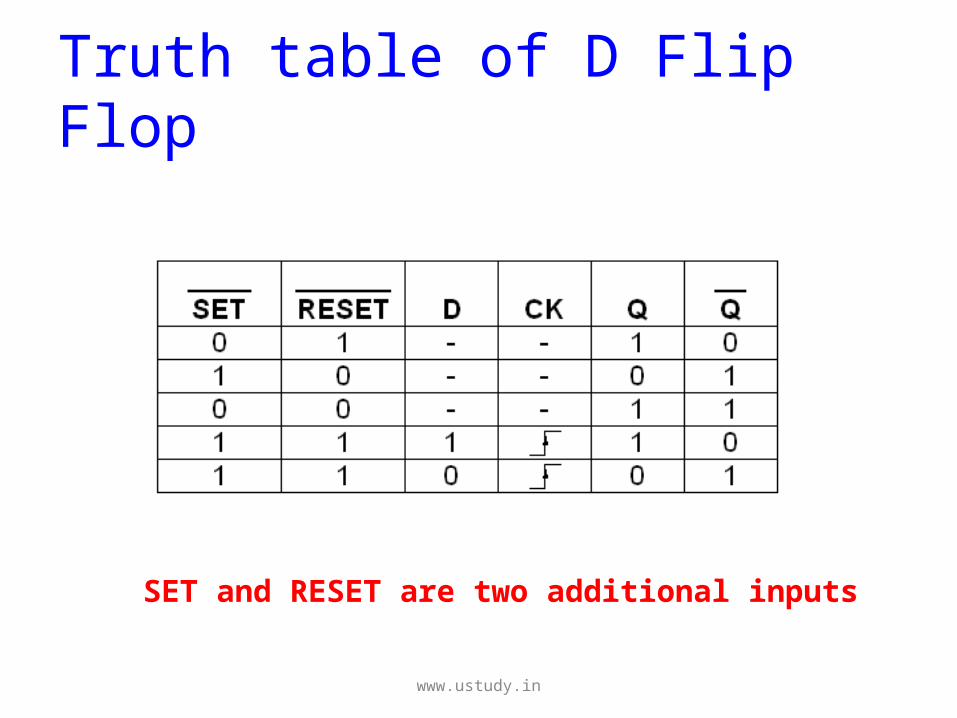
Truth table of D Flip Flop
SET and RESET are two additional inputs
www.ustudy.in
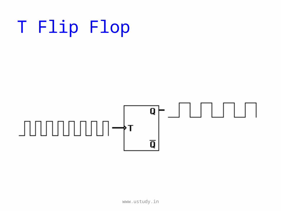
T Flip Flop
• The T or "toggle” flip-flop changes its
output on each clock edge, giving an
output which is half the frequency of the
signal to the T input.
www.ustudy.in
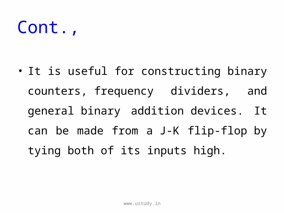
Cont.,
• It is useful for constructing binary
counters, frequency dividers, and
general binary addition devices. It can be
made from a J-K flip-flop by tying both of
its inputs high.
www.ustudy.in
T Flip Flop
www.ustudy.in
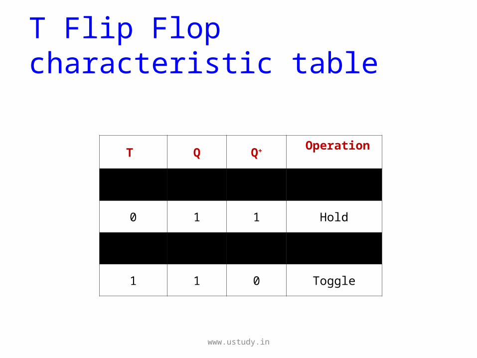
T Flip Flop characteristic table
T Q Q+ Operation
0 0 0 Hold
0 1 1 Hold
1 0 1 Toggle
1 1 0 Toggle
www.ustudy.in
Cont.,
• The T flip flop has two possible values. When T
= 0, the flip flop does a hold.
• A hold means that the output, Q is kept the
same as it was before the clock edge.
www.ustudy.in
Cont.,
• When T = 1, the flip flop does a toggle,
which means the output Q is negated
after the clock edge, compared to the
value before the clock edge.
www.ustudy.in
Cont.,
• Thus, in a T flip flop, you can either
maintain the current state's value for
another cycle, or you can toggle the value
(negate it) at the next clock edge.
www.ustudy.in
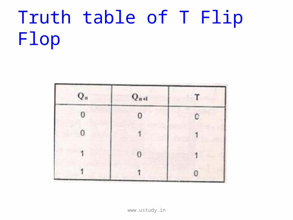
Truth table of T Flip Flop
www.ustudy.in
JK Flip Flop
• A JK flip-flop has two inputs similar to that of RS flip-
flop.
• The two inputs of JK Flip-flop is J (set) and K (reset).
• A JK flip-flop is nothing but a RS flip-flop along with
two AND gates which are augmented to it.
www.ustudy.in
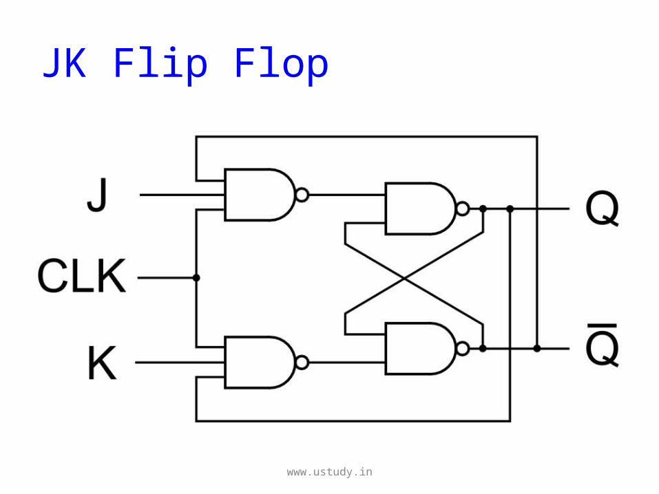
JK Flip Flop
www.ustudy.in
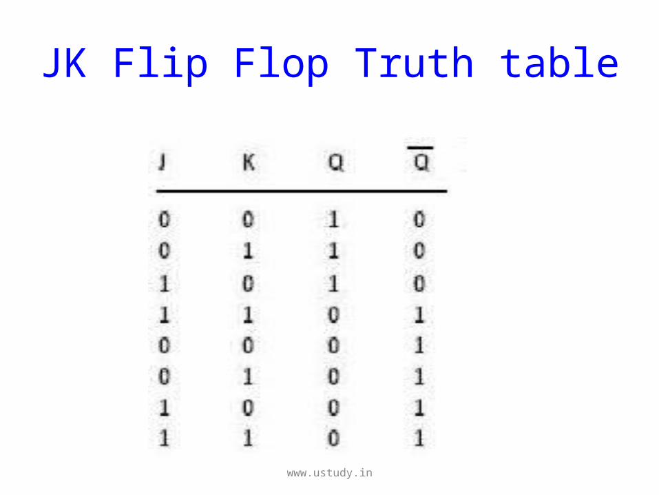
JK Flip Flop Truth table
www.ustudy.in
Working of JK Flip Flop
When J=K=0
• When both J and K are 0, the clock pulse has no
effect on the output and the output of flip-flop is
same as its previous value.
• This is because when both the J and K are 0, the
output of their respective AND gate becomes 0.
www.ustudy.in
Cont.,
When J=0, K=1
• When J=0, the output of the AND gate corresponding to J
becomes 0(i.e.) S=0 and R=1.
• Therefore Q’ becomes 0.
• This condition will reset the flip-flop. This represents the
RESET state of Flip-flop.
www.ustudy.in
Cont.,
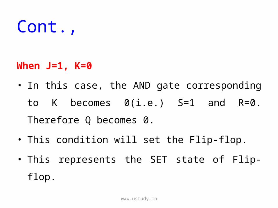
When J=1, K=0
• In this case, the AND gate corresponding to K
becomes 0(i.e.) S=1 and R=0. Therefore Q
becomes 0.
• This condition will set the Flip-flop.
• This represents the SET state of Flip-flop.
www.ustudy.in
Cont.,
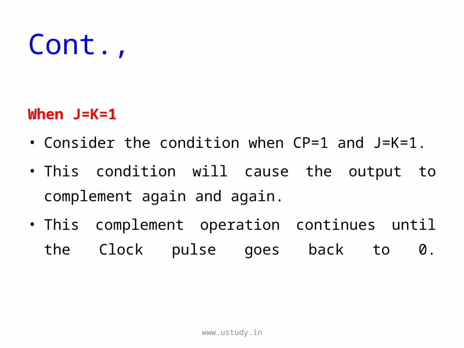
When J=K=1
• Consider the condition when CP=1 and J=K=1.
• This condition will cause the output to
complement again and again.
• This complement operation continues until the
Clock pulse goes back to 0.
www.ustudy.in
Master slave Flip Flop
• A master-slave flip-flop is constructed from two
flip-flops.
• One circuit serves as a master and the other as
a slave, and the overall circuit is referred taps
a master-slave flip-flop.
www.ustudy.in
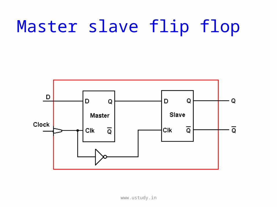
Master slave flip flop
www.ustudy.in
Cont.,
• It consists of a master flip-flop, a slave flip-flop
and an inverter.
• Both the flip-flops are positive level triggered,
but inverter connected at the clock input of the
slave flip-flop forces to trigger at the negative
level.
www.ustudy.in
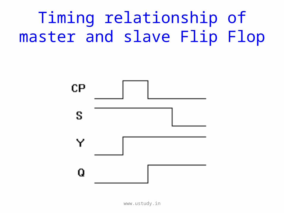
Timing relationship of master and slave Flip Flop
www.ustudy.in
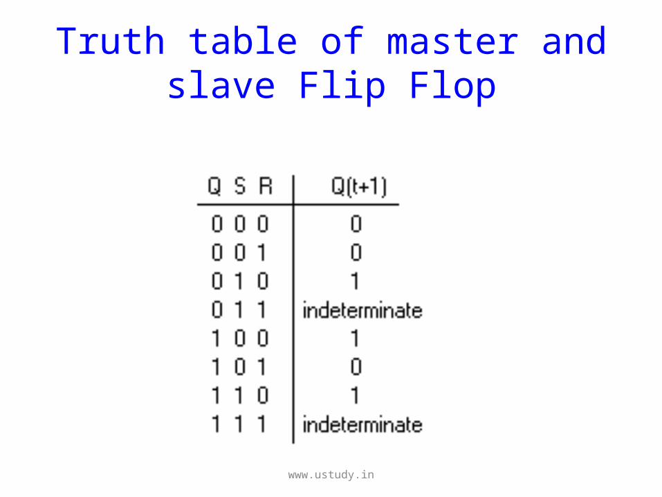
Truth table of master and slave Flip Flop
www.ustudy.in
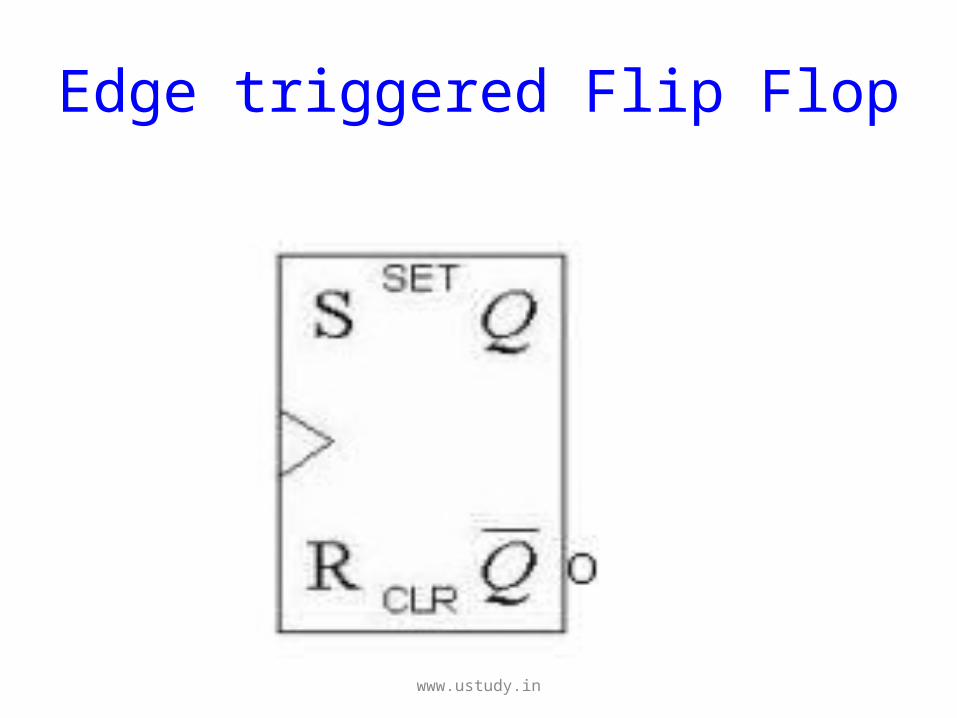
Edge triggered Flip Flop
• An edge-triggered flip-flop changes states
either at the positive edge (rising edge) or at
the negative edge (falling edge) of the clock
pulse on the control input.
www.ustudy.in
Edge triggered Flip Flop
www.ustudy.in
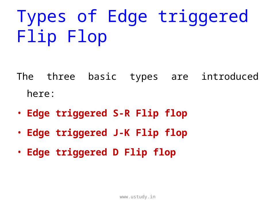
Types of Edge triggered Flip Flop
The three basic types are introduced here:
• Edge triggered S-R Flip flop
• Edge triggered J-K Flip flop
• Edge triggered D Flip flop
www.ustudy.in
Edge triggered S-R Flip flop
• The operation and truth table for a negative
edge-triggered flip-flop are the same as
those for a positive except that the falling
edge of the clock pulse is the triggering
edge.
www.ustudy.in
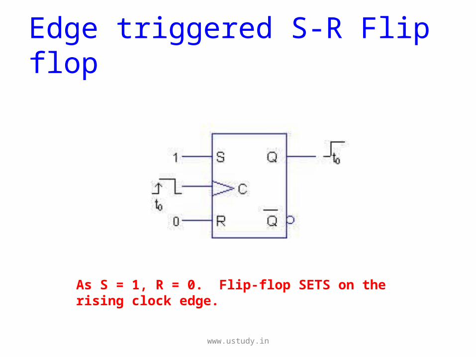
Edge triggered S-R Flip flop
As S = 1, R = 0. Flip-flop SETS on the rising clock edge.
www.ustudy.in
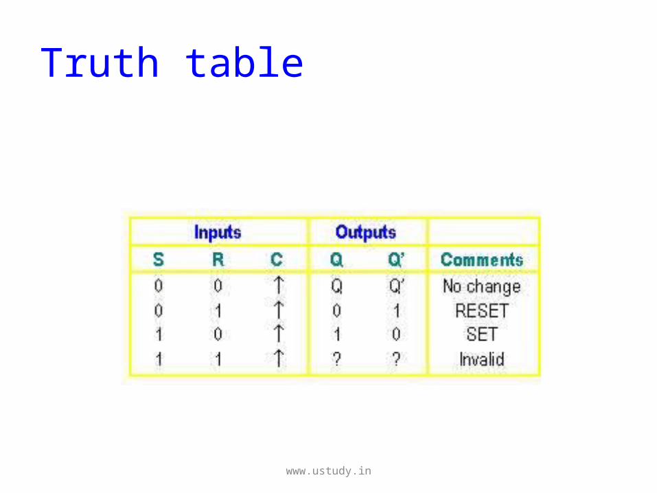
Truth table
www.ustudy.in
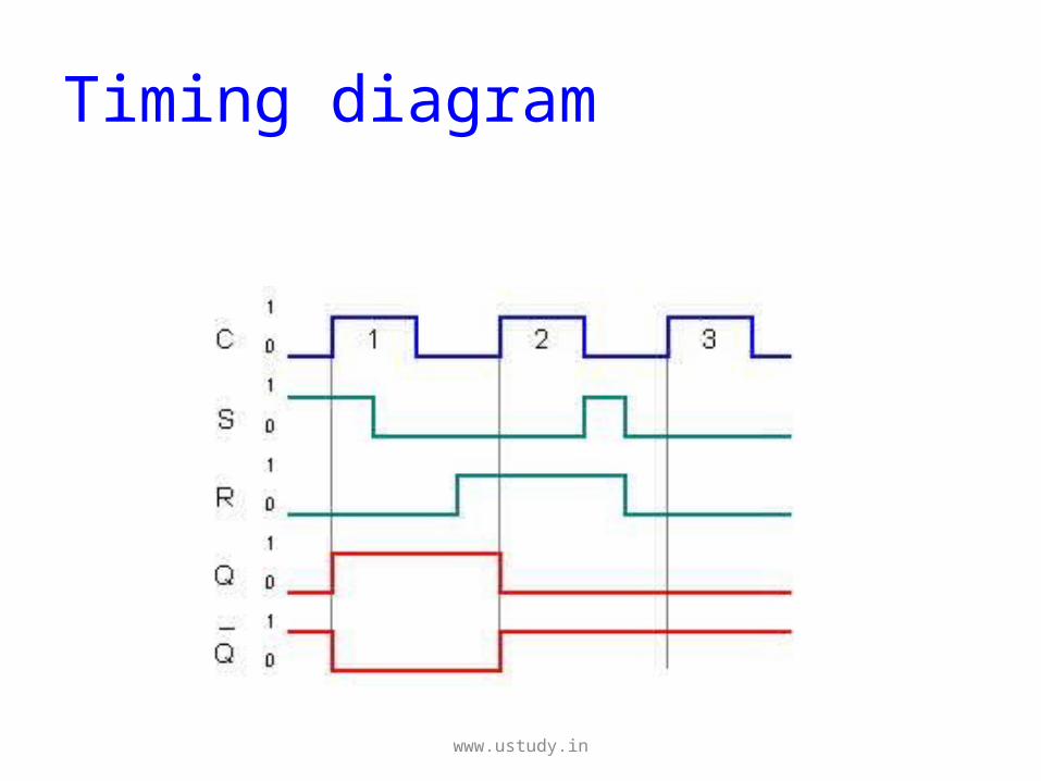
Timing diagram
www.ustudy.in
Edge triggered JK Flip flop
• The J-K flip-flop works very similar to S-R
flip-flop.
• The only difference is that this flip-flop has
NO invalid state.
• The outputs toggle (change to the opposite
state) when both J and K inputs are HIGH.
www.ustudy.in
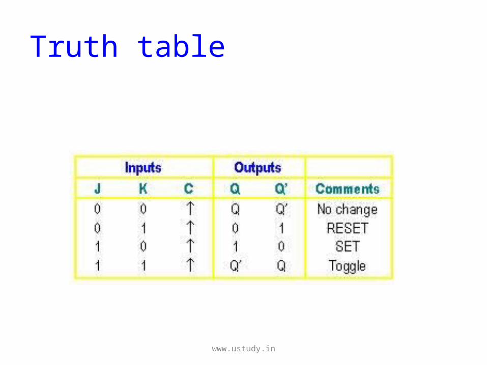
Truth table
www.ustudy.in
Edge triggered D Flip flop
• The operations of a D flip-flop is much more
simpler. It has only one input addition to the
clock.
• It is very useful when a single data bit (0 or 1)
is to be stored.
www.ustudy.in
Cont.,
• If there is a HIGH on the D input when a clock
pulse is applied, the flip-flop SETs and stores a
1.
• If there is a LOW on the D input when a clock
pulse is applied, the flip-flop RESETs and
stores a 0.
www.ustudy.in

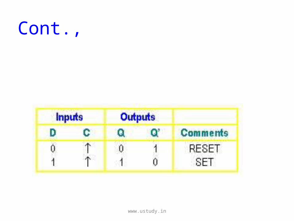
Cont.,
• The truth table below summarize the
operations of the positive edge-triggered D flip-
flop.
• As before, the negative edge-triggered flip-flop
works the same except that the falling edge of
the clock pulse is the triggering edge.
www.ustudy.in
Cont.,
www.ustudy.in

Thank you
M.S.P.V.L POLYTECHNIC COLLEGE,
PAVOORCHATRAM.
www.ustudy.in