Embed Size (px)
Citation preview
Flight test and development of a new anti-g system in JAS 39 GRIPEN
By Christer Berglund, Björn Marklund Saab Aerospace
S-58188 Linköping Sweden
1 ABSTRACT
A new oxygen and anti-g system has been implemented in the Swedish forth generation mulitrole aircraft JAS 39 GRIPEN C and D. In the Gripen the pilot is exposed to 9G for long periods of time. Therefore the Anti-G protection is more important than ever. Due to the implementation of OBOGS (On Board Oxygen Generating System), the anti-g system also had to be changed. During the first test flight with high G-loads with the new OBOGS and anti-G system in GRIPEN test aircraft 39-800 (twin-seat) the pilots got a grey-out and after evaluation of data from the flight it was shown that the pressure in the G-suit was below specified limits. At this time it was suspected to be an individual problem with the G-regulators and therefore they were changed to other units, but due to flight tests of the ECS (Environmental Control System) another problem arose before the anti-G testing could go on. The ECS tests showed that the supply pressure from the ECS during some flight cases was below the minimum requirement that the OBOGS and anti-g system was qualified for. The anti-G tests had to be postponed until the supply pressure to the anti-G system could be guaranteed to be above the minimum requirements. Therefore a number of changes to improve the supply pressure and reduce the pressure drops in the anti-g system were implemented. After a new test period with testing of the modifications, which were successful, the problem with the low pressure in the g-suit still existed even though the G-regulators had been changed. After tests of several G-regulators it was shown that a high percentage of the G-regulators gave a low pressure in the G-suit and quite often below minimum specified values. After some close teamwork with the G-regulator supplier HAY, a modification of the anti-g-regulator was made in order to be able to guarantee correct pressure in the g-suit. This paper describes the testing and the development changes made on the anti-g system and the way forward to qualify the system up to 9 G. It also describes high G-loads, a G-LOC and the importance of a good Anti-G protection from the pilot’s perspective.
Copyright© Christer Berglund, Björn Marklund
34
Report Documentation Page Form ApprovedOMB No. 0704-0188
Public reporting burden for the collection of information is estimated to average 1 hour per response, including the time for reviewing instructions, searching existing data sources, gathering andmaintaining the data needed, and completing and reviewing the collection of information. Send comments regarding this burden estimate or any other aspect of this collection of information,including suggestions for reducing this burden, to Washington Headquarters Services, Directorate for Information Operations and Reports, 1215 Jefferson Davis Highway, Suite 1204, ArlingtonVA 22202-4302. Respondents should be aware that notwithstanding any other provision of law, no person shall be subject to a penalty for failing to comply with a collection of information if itdoes not display a currently valid OMB control number.
1. REPORT DATE OCT 2005
2. REPORT TYPE N/A
3. DATES COVERED -
4. TITLE AND SUBTITLE Flight Test and Development of a New Anti-G System in JAS 39 Gripen
5a. CONTRACT NUMBER
5b. GRANT NUMBER
5c. PROGRAM ELEMENT NUMBER
6. AUTHOR(S) 5d. PROJECT NUMBER
5e. TASK NUMBER
5f. WORK UNIT NUMBER
7. PERFORMING ORGANIZATION NAME(S) AND ADDRESS(ES) Saab Aerospace S-58188 Linkoping Sweden
8. PERFORMING ORGANIZATIONREPORT NUMBER
9. SPONSORING/MONITORING AGENCY NAME(S) AND ADDRESS(ES) 10. SPONSOR/MONITOR’S ACRONYM(S)
11. SPONSOR/MONITOR’S REPORT NUMBER(S)
12. DISTRIBUTION/AVAILABILITY STATEMENT Approved for public release, distribution unlimited
13. SUPPLEMENTARY NOTES Published in the Proceedings of the Forty Third Annual SAFE Association Symposium, Held in the SaltLake City, Utah, October 24-26, 2005. SAFE Assocation, Post Office Box 130, Creswell, OR 97426-0130. http://www.safeassociation.org
14. ABSTRACT
15. SUBJECT TERMS Safe
16. SECURITY CLASSIFICATION OF: 17. LIMITATION OF ABSTRACT
SAR
18. NUMBEROF PAGES
16
19a. NAME OFRESPONSIBLE PERSON
a. REPORT unclassified
b. ABSTRACT unclassified
c. THIS PAGE unclassified
Standard Form 298 (Rev. 8-98) Prescribed by ANSI Std Z39-18

2 ACRONYMS, ABBREVIATIONS, SYMBOLS AGTp Anti-G trouser pressure APU Auxillary Power Unit ATP Acceptance Test Procedure BRAG-valve Breathing and anti-G valve COMET Compact Measurement and Test system ECS Environmental Control System FADEC Full Authority Digital Engine Control FCS Flight Control System FLIR/LDP Forward Looking Infra-Red/Laser Designator Pod GECU General systems Electronic Control Unit Gripen Swedish for Griffin, a mix between an eagle and a lion HAY Honeywell Aerospace, Yeovil UK HMD Helmet-Mounted Display HOUSTON TM-central at Saab kPa KiloPascal (Pressure) LGB Laser-Guided Bomb OBOGS On Board Oxygen Generating System PRV Pressure Reducing Valve PSU Pilot Services Unit TM Telemetry
3 INTRODUCTION Gripen is the first new-generation multi-role/swing-role combat aircraft to enter service. It is designed to meet the demands of current and future threat scenarios, whilst at the same time meeting stringent requirements with regard to flight safety, availability, training efficiency and life cycle cost. Fully integrated digital systems give Gripen the brainpower to use its strength and the intelligence to use its muscles to maximum effect. Its pilots can share real-time tactical information with friendly forces while remaining undetected by the enemy. Gripen was declared operational in the Swedish Air Force in 1997, and has there achieved 40,000 flying hours in five fully operational, multi-mission squadrons. Superior air-to-air combat capability at beyond visual range (BVR) is achieved through a combination of aircraft performance, modern sensor systems, the world’s most developed in-service tactical datalink and the capability to launch advanced active-radar BVR missiles. When combined with an inherent low-visual, low-radar and low infrared signature, this gives Gripen a decisive combat advantage over its competitors. At closer ranges, Gripen’s combat capability is assured through the combination of its delta-canard configuration and relaxed stability. This gives excellent agility and high instantaneous turn rates during combat maneuvers. In addition to the radar’s close combat modes, a helmet-mounted display (HMD) can be used by Gripen pilots to cue the seekers of the latest agile short-range high off borsight air-to-air missiles.
35

The aircraft has stores recognition, and the weapon system is continuously communicating with the FCS to optimize performance and maintain the instability and outstanding turnrate. The Load Limiter permits the pilot to fully concentrate on the outside close combat scenario without risking overstressing or stalling the aircraft. Control of the battlefield during air-to-surface operations calls for the aircraft to deal with a wide range of targets with a great variety of weapons. Gripen carries a number of advanced weapons that are supremely effective over land and at sea. Gripen’s weapon system includes 'smart' precision munitions such as laser-guided bombs (LGBs) and their associated forward looking infra-red/laser designator pod (FLIR/LDP) targeting equipment. These advanced targeting sensors complement the dedicated air-to-surface radar modes and tactical data link to give Gripen a flexible and effective precision attack capability. With a ground turnaround time less then 10 minutes for Air to Air (AA) missions and 20 minutes for Air to Ground (A/G) missions, the availability is one of a kind. The previous oxygen system in the Gripen A/B, uses compressed oxygen stored in pressurized bottles. For the latest version of the Gripen C (single-seat A/C) and D (twin-seat A/C). a new oxygen and anti-g system has been implemented. Due to air to air refuelling capability and 8-10 hours missions, the former oxygen supply was insufficient and therefore the Gripen was modified with an On Board Oxygen Generating System (OBOGS), a system that generates oxygen to the pilot supplied from the Environmental Control System. Due to the implementation of OBOGS, the anti-g system also had to be changed because the old system needed a minimum supply pressure of 450 kPa and the tapping point from the ECS could only guarantee around 200 kPa.
4 TESTING AND DEVELOPMENT
4.1 Factors for Anti-G resistance When flying the high performance jets of the new generation fighters, maneuvers adds nine times the weight of gravity to the mass of the pilot body. It causes fatigue, and may also cause blackout, and in the worst case, death. This happens because gravity drives blood, which transports oxygen to the heart, lungs and brain, from these organs and down to the lower parts of the body. Waking up from a G-LOC (Gravity caused Loss Of Consciousness), the pilot has no idea where he is, nor what he is doing. This can take some time up to minutes and before he realizes what he is doing. Before he gets it all back, he is unable to, for example, avoid the terrain if heading towards the ground. The pilots anti-g capacity consists of some contributing factors, such as; dehydration, nutritional balance, if exposed for any infection, and also or if he has slept well. The body is also trying to fight the rising g-loads; the brain senses the decreasing blood pressure and commands the heart to pump faster to increase the pressure.
36
One other important factor is the anti-g suit, where the most significant characteristics are the time from onset to full inflation, the maximum pressure and finally the coverage (in percent). The anti-g suit is supposed to protect the pilot from G-LOC. The suit is filled with compressed air, and when the loads (nz) increases, the suit squeezes the pilot lower body, preventing this from happening, by shove body fluids upwards. And finally the traditional M1 maneuver. This specific maneuver is done by the pilot to maintain conscious, while accelerating and sustaining high G (nz). Before the acceleration the pilot strains the muscles and holds his breath to maintain and raise the blood pressure in the brain. When the high G (nz) is achieved, the pilot then tries to breathe every third or fourth second to ventilate the lungs without letting the pressure off. The Swedish full coverage anti-g suit is however very efficient. When achieved 9G the pilot can relax. Start to relax in the abdominal region, then the butt and finally the legs and calves.
4.2 Low pressure in the G-suit and Low supply pressure from ECS During the first test flight with high G-loads with the new OBOGS and anti-G system in GRIPEN test aircraft 39-800 (twin-seat) the pilots got a grey-out. The sortie when the problem was discovered was planned as an envelop expansion regarding the new anti-g system for the Gripen 39 C/D version. The mission was planned as a built-up and started at nz 5. Nz 5 was maintained for 15 seconds and the load was then decreased to nz1. Slow, medium and rapid onset rates were used. The same procedure was planned to nz 6, 7, 8 and 9. When pulling 6 g with a rapid onset rate, the rear pilot, expressed a slightly visual change but thought it was just a bad performed M1 maneuver. At nz 7 the rear pilot also thought that he had a bad day. He had some impact on the periphery vision, and he felt that it was heavier than expected to maintain a clear vision. When finally communicating with the front pilot he admitted the same expressions. The flight was aborted, and after evaluation of data from the flight it was shown that the pressure in the G-suit was below specified limits. At this time it was suspected to be an individual problem with the G-regulators and therefore they were changed to other units, but due to flight tests of the ECS (Environmental Control System) another problem arose before the anti-G testing could go on. The ECS tests showed that the supply pressure from the ECS during some flig8ht cases was below the minimum requirement that the OBOGS and anti-g system was qualified for. See figure 1 for a graph of the supply pressure to the Anti-G system during a flight.
37

Figure 1 Supply Pressure to the OBOGS and Anti-G Systems
4.3 Changes made to improve the safety on the Anti-G system A number of changes to improve the supply pressure and reduce the accident contribution value were implemented:
• An increased flight idle setting in FADEC was implemented to improve the ECS supply pressure.
• The GECU s/w was modified to improve the ECS supply pressure.
The ECS for the Gripen is a common bootstrap system with a combined compressor and turbine and two ram air heat exchangers. The tapping point to the OBOG and Anti-g system is situated between the compressor and the turbine, which means that the pressure is not controlled to a certain level, it is a function of the flow passing through the turbine, the more flow the higher pressure.
The ECS team started to analyze what was causing every pressure drop and then tuned the software to avoid those pressure drops. Among other changes, the most significant were introducing a ramp function instead for a step function for the temperature control valves and overcooling the Avionics slightly.
38

• New pipe work and a new PRV (Pressure Reducing Valve) were installed to decrease the pressure drop in the anti-g system. This reduced the pressure losses with around 40 kPa
• The requirements were modified to match the capability of the aircraft.
As a result of the work to find a solution to this problem it was noted that the requirement for anti-g protection was over specified. In the vendor specification for the anti-g system, a need of anti-g protection of 1-9 g with a g rate of 15 g/s up to an altitude of 16 km was stated, in combination with maximum breathing flow.
Bye reducing the maximum g-rate and eliminating test positions that was impossible to reach in real flight, since the ability to pull high g-loads at high altitude and low speed is limited, the required supply pressure could be reduced
• A new qualification of the OBOG and Anti-G system for the new pipe work and PRV
together with the lower supply pressure were done by the vendor HAY
• A new warning to the pilot if the pressure to the OBOGS and anti-g system was too low, the warning level is set to 150 kPa in 39C. This warning was needed to reduce the accident contribution.
The two first changes were done to improve the supply pressure, while the latter were done to reduce the needed pressure level.
39

4.4 Flight tests after the changes The changes made to improve the supply pressure from the ECS and reduce the pressure losses in the Anti-G system was successful, see trace below for the supply pressure after the changes. The pressure was always above the minimum specification limits with quite good margins.
Figure 2 ECS supply pressure after Anti-g modifications. Note that the pressure dip in the
beginning is the changeover from APU to Engine supply The supply pressure from the ECS have been raised from around 120 kPa to around 180 kPa and generally the pressure level had gone up approximately 50-70 kPa during similar test conditions. As a result of the change of the PRV and the modification of the pipe work, the need for supply pressure from the ECS was reduced from 200 kPa to 150 kPa due to the reduction of pressure losses in the system. These changes together with the warning for low ECS supply pressure have significantly improved the Anti-G system safety.
40
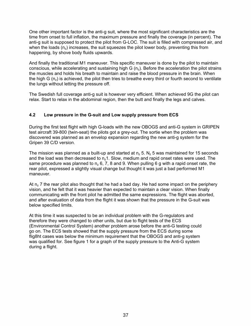
4.5 Low pressure in the G-trousers When the new Anti-g testing period finally could be resumed, it was found after several tests with the improved system that some G-regulators gave to low pressure in the G-suit. Often the pressure in the G-suit showed 3-8 kPa lower pressure in the G-suit during flight tests than during ATP tests at the vendor. Also the vendor often send G-regulators that was just inside there ATP limits. See figure 3 for a graph of the G-trouser pressure during a flight.
Figure 3 Upper part G-load
Lower part pressure in the G-trousers with maximum and minimum requirements.
41
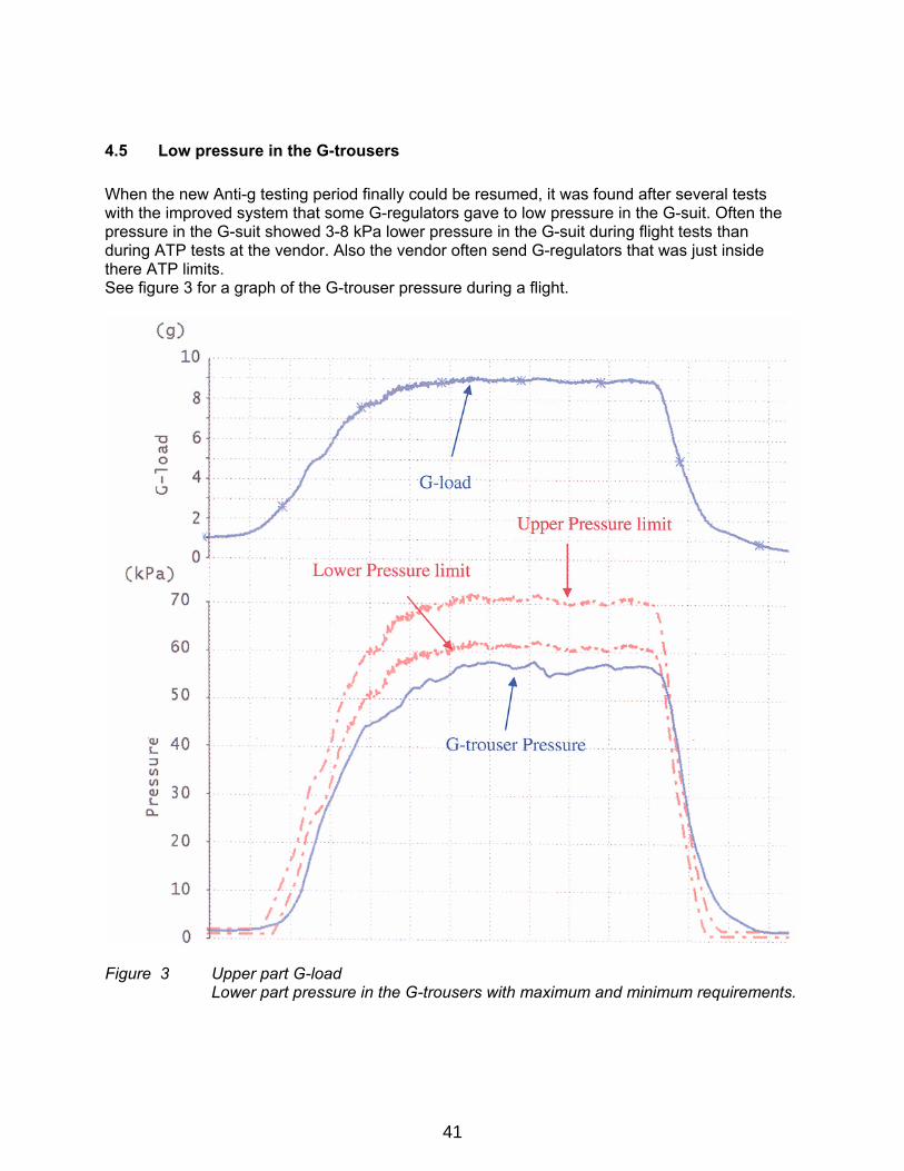
To be able to deliver G-regulators with full G-envelope it was decided that all G-regulators were to be flight tested in A/C before delivery. But after flight tests of 10 G-regulators and only 3 passed the test with good G-suit pressure, it was realised that this was not an accessible way, something more radical had to be done. See figure 4 below for the spread received at flight testing
Flight test with G-regulator before the modificationAGTp pressure as function of Nz 7, 8 and 9 g turns
40
45
50
55
60
65
70
75
6,5 7 7,5 8 8,5 9 9,5
Plato Nz (g)
AG
Tp (k
Pa)
PSU 0032PSU 0034PSU 0039PSU 0008PSU 0007PSU 0020PSU 0023PSU 0043Min Max
Figure 4 The spread in the G-trouser pressure for some of the G-regulators received at
flight testing The few G-regulators that had been acceptable during these tests had all had high pressure in the G-suit during ATP test, and the G-regulators that were not acceptable the G-suit pressure were just inside minimum specification limits at ATP tests, but because of the design of the G-regulator it was not possible to adjust all G-regulators to give high ATP values. Therefore it was decided that the ATP levels had to be changed if the pressure in the G-suit should be inside Saab specification limits due to the fact that the pressure in the G-suit was often 3-8 kPa lower in flight tests than during the vendors ATP tests. See figure 5 for the upgraded ATP specification.
42
New HAY ATP, Gripen specand g-trousers max pressure
0
10
20
30
40
50
60
70
80
0 2 4 6 8 10
g-load
g-Tr
ouse
r kPa min/HAY
max/HAYmin/Saabmax/Saab
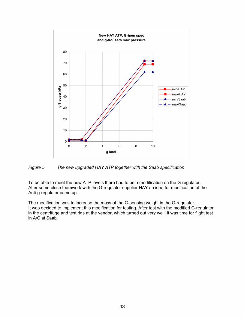
Figure 5 The new upgraded HAY ATP together with the Saab specification To be able to meet the new ATP levels there had to be a modification on the G-regulator. After some close teamwork with the G-regulator supplier HAY an idea for modification of the Anti-g-regulator came up. The modification was to increase the mass of the G-sensing weight in the G-regulator. It was decided to implement this modification for testing. After test with the modified G-regulator in the centrifuge and test rigs at the vendor, which turned out very well, it was time for flight test in A/C at Saab.
43
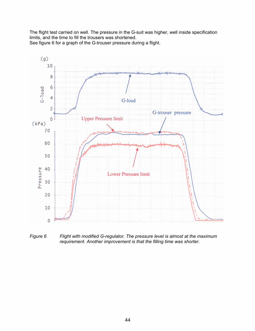
The flight test carried on well. The pressure in the G-suit was higher, well inside specification limits, and the time to fill the trousers was shortened. See figure 6 for a graph of the G-trouser pressure during a flight.
Figure 6 Flight with modified G-regulator. The pressure level is almost at the maximum
requirement. Another improvement is that the filling time was shorter.
44
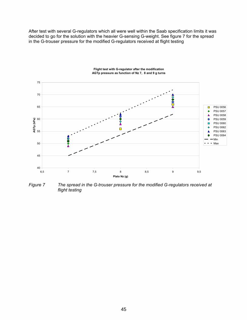
After test with several G-regulators which all were well within the Saab specification limits it was decided to go for the solution with the heavier G-sensing G-weight. See figure 7 for the spread in the G-trouser pressure for the modified G-regulators received at flight testing
Flight test with G-regulator after the modificationAGTp pressure as function of Nz 7, 8 and 9 g turns
40
45
50
55
60
65
70
75
6,5 7 7,5 8 8,5 9 9,5
Plato Nz (g)
AG
Tp (k
Pa)
PSU 0056PSU 0057PSU 0058PSU 0059PSU 0060PSU 0062PSU 0063PSU 0064Min Max
Figure 7 The spread in the G-trouser pressure for the modified G-regulators received at
flight testing
45
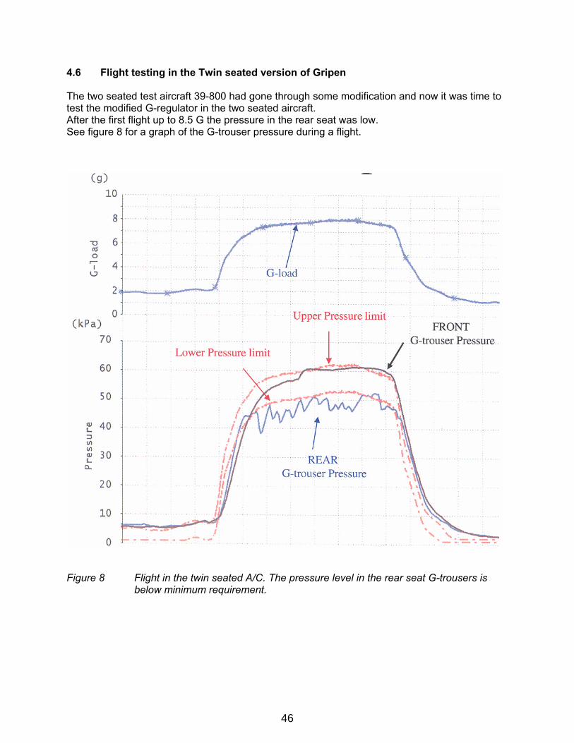
4.6 Flight testing in the Twin seated version of Gripen The two seated test aircraft 39-800 had gone through some modification and now it was time to test the modified G-regulator in the two seated aircraft. After the first flight up to 8.5 G the pressure in the rear seat was low. See figure 8 for a graph of the G-trouser pressure during a flight.
Figure 8 Flight in the twin seated A/C. The pressure level in the rear seat G-trousers is
below minimum requirement.
46

4.7 Vibration tests Since both BRAG-valves had been tested in single seat aircraft with good result it was decided to shift the front and rear seat PSU. After the flight test the BRAG-valve that had given good pressure in the front seat now gave low pressure in the rear seat and the BRAG-valve that had given low pressure in the rear seat gave good pressure in the front seat. At this time it was thought that it might be vibrations that caused the low G-trouser pressure in the rear seat. To be able to clarify if it was vibration that caused the low g-trouser pressure, accelerometers were mounted on both the front and rear seat See figure 9 for traces from vibration analyze made after the flight test
Front seat Rear seat Figure 9 Flight in the twin seated A/C. The vibration level in the rear seat is distinctly
higher than in the front seat. As you can see the vibration level is distinctly higher in the rear seat compared to the front seat. Even though that the vibration level measured, was well inside specification values what the BRAG-valve was qualified for, the G-trouser pressure was below minimum specified requirements. Why the BRAG valve did not perform at these vibration levels was now examined. After thoroughly analyzing the qualification test report for the BRAG-valve, it was found that the vibration tests made at HAY during the qualification tests were done incorrect. The vibration tests were done with a simulated G that was performed by mechanically pressing on the G-sensing weight instead for testing in a centrifuge together with vibration. This since the vendor did not have the possibility and also believed that they did not need to put a vibrator on the centrifuge. Due to this it was not found that the BRAG valve was sensitive against vibrations, during the qualification tests.
47
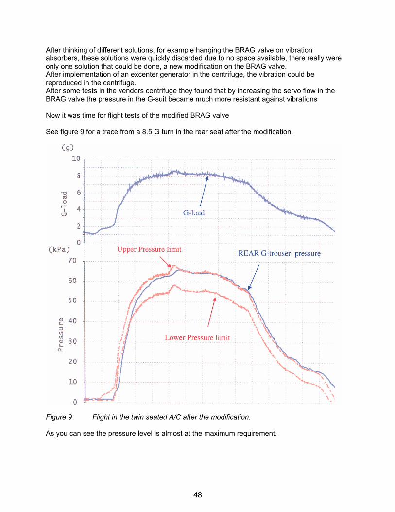
After thinking of different solutions, for example hanging the BRAG valve on vibration absorbers, these solutions were quickly discarded due to no space available, there really were only one solution that could be done, a new modification on the BRAG valve. After implementation of an excenter generator in the centrifuge, the vibration could be reproduced in the centrifuge. After some tests in the vendors centrifuge they found that by increasing the servo flow in the BRAG valve the pressure in the G-suit became much more resistant against vibrations Now it was time for flight tests of the modified BRAG valve See figure 9 for a trace from a 8.5 G turn in the rear seat after the modification.
Figure 9 Flight in the twin seated A/C after the modification. As you can see the pressure level is almost at the maximum requirement.
48
5 LESSONS LEARNED Time could have been saved if the initial Anti-G testing could have continued with more anti-G testing. We would then have realised that there was not an individual fault on the G-regulator, but a more serious problem. The specification limits for the supplier ATP should not be the same as the limits in the A/C specification. It is possible to do a lot of work fast if there is a close cooperation between different departments like system-, flight test- and design- departments if everyone drop there ego and work as a team instead, where everyone’s voice is equally important . We had a very close cooperation between the different departments and this was vital to be able to do these modifications in such a short time.
6 CONCLUSIONS The changes made to improve the supply pressure from the ECS and changes made on the Anti-G system to reduce the pressure drops were successful. The change to the heavier G-sensitive weight improved the pressure in the G-suit as well as the filling time of the G-trousers. To summarize we have had a lot of problems with the anti-G system but we have solved all of them and now we have a very good anti-G system that you can rely on 100%.
7 BIOGRAPHY/PHOTOGRAPH
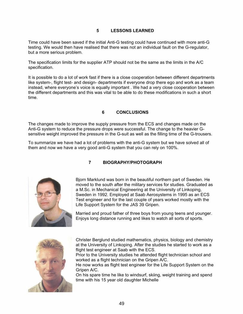
Bjorn Marklund was born in the beautiful northern part of Sweden. He moved to the south after the military services for studies. Graduated as a M.Sc. in Mechanical Engineering at the University of Linkoping, Sweden in 1992. Employed at Saab Aerosystems in 1995 as an ECS Test engineer and for the last couple of years worked mostly with the Life Support System for the JAS 39 Gripen. Married and proud father of three boys from young teens and younger. Enjoys long distance running and likes to watch all sorts of sports. Christer Berglund studied mathematics, physics, biology and chemistry at the University of Linkoping. After the studies he started to work as a flight test engineer at Saab with the ECS. Prior to the University studies he attended flight technician school and worked as a flight technician on the Gripen A/C. He now works as flight test engineer for the Life Support System on the Gripen A/C. On his spare time he like to windsurf, skiing, weight training and spend time with his 15 year old daughter Michelle
49