Embed Size (px)
Citation preview

Anflo 1 21st Annual AIAA/USU Conference on Small Satellites
SSC07-X-2
FLIGHT DEMONSTRATION OF NEW THRUSTER AND GREEN PROPELLANT TECHNOLOGY ON THE PRISMA SATELLITE
Anflo K., Bergman G., Hasanof t., Kuzavas L., Thormählen P., Åstrand B.
ECAPS P.O. Box 4207 SE-171 o4 Solna, Sweden; +46 8 6276200
E-mai: [email protected]
ABSTRACT The concept of a storable liquid monopropellant blend for space applications based on Ammonium Dinitramide (ADN) was invented in 1997, within a co-operation between the Swedish Space Corporation (SSC) and the Swedish Defense Research Agency (FOI). The objective was to develop a propellant which has higher performance and is safer than hydrazine. The work has been performed under contract from the Swedish National Space Board and ESA. The progress of the development has been presented in several papers since 2000.
ECAPS, a subsidiary of the Swedish Space Corporation was established in 2000 with the aim to develop and market the novel “High Performance Green Propellant” (HPGP) technology for space applications. The new technology is based several innovations and patents w.r.t. propellant formulation and thruster design, including a high temperature resistant catalyst and thrust chamber.
The first flight demonstration of the HPGP propulsion system will be performed on PRISMA. PRISMA is an international technology demonstration program with Swedish Space Corporation as the Prime Contractor.
This paper describes the performance, characteristics, design and verification of the HPGP propulsion system for PRISMA. Compatibility issues related to using a new propellant with COTS components is also discussed. The PRISMA mission includes two satellites in LEO orbit were the focus is on rendezvous and formation flying. One of the satellites will act as a “target” and the main spacecraft performs rendezvous and formation flying maneuvers, were the ECAPS HPGP propulsion system will provide delta-V capability.
The PRISMA CDR was held in January, 2007. Integration of the flight propulsion system is about to be finalized.
The flight opportunity on PRISMA represents a unique opportunity to demonstrate the HPGP propulsion system in space, and thus take a significant step to towards its use in future space applications. The launch of PRISMA scheduled to 2009.

Anflo 2 21st Annual AIAA/USU Conference on Small Satellites
INTRODUCTION
Background
The state-of-the-art of storable monopropellant space propulsion systems uses hydrazine as propellant. The demand for higher performance and reduced hazards for an overall lower cost makes it desirable to replace hydrazine. The potential and benefits of a new “Green” or Reduced Hazard Propellants has been assessed by several organizations and are further described in several papers [8-21].
Swedish Space Corporation and ECAPS have since 1997, under the previous and ongoing contracts with the Swedish National Space Board (SNSB) and the European Space Agency (ESA), successfully performed research and development of ADN-based monopropellants and associated rocket engines. TRL-6 was achieved in 2007 for the propellant (LMP-103S) and propulsion system (including the thruster). The development of the propellant and the thruster has previously been described in [1-7]. ADN-based monopropellant candidates have been tested with >10% higher specific impulse and >30% higher density, compared to Hydrazine. However, considering other requirements mainly engine life, the chosen propellant for the PRISMA mission LMP-103S, has a theoretical specific impulse of 2477 Ns/kg (252 sec) for an expansion ratio of 50:1. The demonstrated specific impulse is >2300 Ns/kg which is ~5% higher than for a corresponding hydrazine thruster but with a propellant density which is 24% higher. The demonstrated steady-state density impulse is >2850 Ns/kg for a 1 N thruster operated with LMP-103S. The improved density impulse is a major benefit for the accommodation of the propulsion system on small spacecraft.
HPGP Flight Demonstration
The Flight Demonstration on the PRISMA satellite fulfils the following major objectives:
1) A successful spaceflight demonstration of a novel monopropellant, which is storable and compared with hydrazine gives higher performance, is environmentally benign and has reduced handling hazards would be a major step forward in chemical propulsion since the first flight with Hydrazine more than 40 years ago.
2) Successfully fulfilling the PRISMA mission requirements, typical for near term LEO and MEO space missions [22], will demonstrate HPGP technology’s ability to meet the requirements on such missions and will shorten the time to market.
HPGP PROPULSION SYSTEM DESCRIPTION
The PRISMA HPGP system consists of one diaphragm-type propellant tank with a capacity of 4.5 L (i.e. 5.6 kg) of propellant, two service valves, one pressure transducer, one system filter, one isolation latch valve and two 1 N monopropellant thrusters.
All fluid components are conventional hydrazine “Commercial Off-The-Shelf” (COTS) components including the Thruster Flow Control Valve. The hydraulic schematic is shown in figure 1.
Figure 1. The HPGP Hydraulic Schematic
The propulsion system also consists of ¼” CRES tubing to distribute the pressurant and propellant, and all fluid components are welded to the tubing. In addition, the system also consists of brackets, thermal hardware, electrical connectors and harnesses.
The system operates in blow-down mode, meaning that the feed pressure decreases proportional to the amount of consumed propellant. The nominal Beginning of Life (BOL) feed pressure is 2.2 MPa at 20 ˚C. With a blow-down ratio of 4:1, the feed pressure will decrease to 0.55 MPa when all propellant is consumed. The thrust will due to the change of feed pressure decrease from its beginning of life ~1 N to ~0.25 N. The propellant and the pressurant gas are stored in the tank and are separated by means of a diaphragm. The pressurant (helium) acts on the flexible diaphragm and pushes the propellant via the system filter to the thruster propellant flow control valve.
LMP-103S
GHe
Propellant Service Valve
Orifice
Filter Latch Valve
Thrusters
Pressurant ServiceValve
Pressure Transducer
Anflo 3 21st Annual AIAA/USU Conference on Small Satellites
The thruster requires preheating prior to firing. When the firing command is given, the series redundant propellant Flow Control Valve (FCV) opens and enables the propellant to enter into the thrust chamber. The propellant decomposes and ignites in the pre-heated reactor bed, thus generating hot gases and thereby thrust.
The pressure transducer and tank temperature sensor are utilized for propellant gauging. All components are powered by a Remote Terminal Unit (RTU) with 28 ± 1 VDC. The RCS temperature is controlled by a Thermal Control Remote Terminal Unit (TCRTU), and shall be kept in the range of +10 to +50˚C during the entire mission (except for the thruster inc. valve) that will run hotter during, and shortly after firing.
The HPGP dry mass is 3.9 kg (including brackets and thermal hardware) and the wet mass is 9.5 kg.
Figure 2. The HPGP Propulsion System Layout
THRUSTER DEVELOPMENT The design and function of rocket engines developed for ADN-based monopropellant blends have several similarities with hydrazine thrusters. The major difference is that the ADN propellants have more complex decomposition pathways. As the average exhaust molecule mass is higher for ADN propellants than for hydrazine, the propellant has to be formulated so that the combustion temperature is significantly higher as compared to hydrazine to achieve the same specific impulse. The high combustion temperature has been the major challenge with respect to design of the reactor and thrust chamber.
Since 1999 more than 30 thrusters (including experiment, development and engineering models) have been build and tested. The PRISMA 1N HPGP thruster
is based on Engineering Mode (EM-1) that was developed and tested during Phase-3A under contract with ESA.
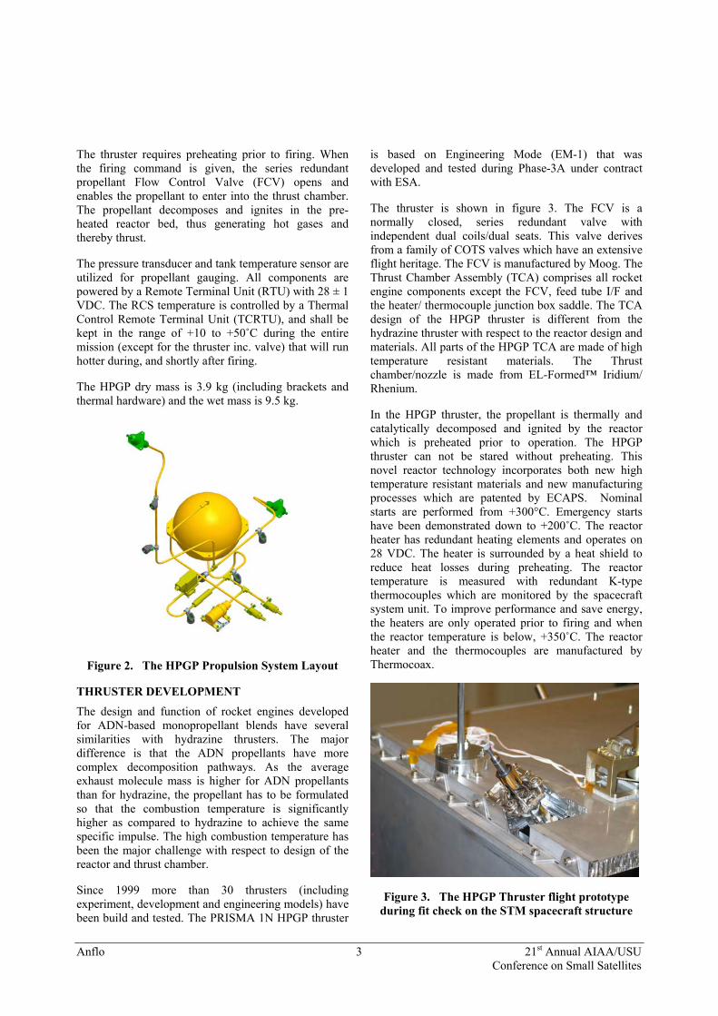
The thruster is shown in figure 3. The FCV is a normally closed, series redundant valve with independent dual coils/dual seats. This valve derives from a family of COTS valves which have an extensive flight heritage. The FCV is manufactured by Moog. The Thrust Chamber Assembly (TCA) comprises all rocket engine components except the FCV, feed tube I/F and the heater/ thermocouple junction box saddle. The TCA design of the HPGP thruster is different from the hydrazine thruster with respect to the reactor design and materials. All parts of the HPGP TCA are made of high temperature resistant materials. The Thrust chamber/nozzle is made from EL-Formed™ Iridium/ Rhenium.
In the HPGP thruster, the propellant is thermally and catalytically decomposed and ignited by the reactor which is preheated prior to operation. The HPGP thruster can not be stared without preheating. This novel reactor technology incorporates both new high temperature resistant materials and new manufacturing processes which are patented by ECAPS. Nominal starts are performed from +300°C. Emergency starts have been demonstrated down to +200˚C. The reactor heater has redundant heating elements and operates on 28 VDC. The heater is surrounded by a heat shield to reduce heat losses during preheating. The reactor temperature is measured with redundant K-type thermocouples which are monitored by the spacecraft system unit. To improve performance and save energy, the heaters are only operated prior to firing and when the reactor temperature is below, +350˚C. The reactor heater and the thermocouples are manufactured by Thermocoax.
Figure 3. The HPGP Thruster flight prototype during fit check on the STM spacecraft structure

Anflo 4 21st Annual AIAA/USU Conference on Small Satellites
Firing Tests
Pulses fired between 10ms and 10 minutes have been demonstrated. Figures 7a and 7b shows the thrust traces for 100 ms pulses at Beginning Of Life (BOL) and End Of Life (EOL) conditions, i.e., at propellant feed pressures of 2.2 and 0.55 MPa. Figure 8 shows the thrust trace for a 30 s steady state firing at 2.2 MPa feed pressure.
Figure 6. PRISMA 1 N HPGP Development Model during steady-state firing
Figure 7a. Thrust trace, 100 ms pulse at BOL
Figure 7b. Thrust trace, 100 ms at EOL
Figure 8. Thrust trace, 30 s pulse at BOL
Thruster Verification
For the verification for PRISMA two thrusters were manufactured and tested: one Development Model, Rocket Engine Assembly (REA) #26 and one Flight Prototype Model (REA #29). The HPGP thruster life test was performed on Development Model REA #26. The test was concluded as planned in July, 2006, see Table 1. The thruster Isp decreased with ~ 1 % during the first hour of firing. Thereafter no further degradation of the thruster performance was observed. Post-test inspection showed no indications of degradation or damage. Within the ESA contract the thruster will be tested with a propellant throughput up to 20 kg.
Table 1
1N HPGP Thruster Life Test (REA #26)
Thrust at 2.2 MPa (Steady State Firing)
1 N
Specific Impulse at 2.2 MPa (Steady State Firing)
2300 Ns/kg (@ BOL) (234 s)
Density Impulse at 2.2 MPa (Steady State Firing)
~2852 Ns/L (@BOL)
Nominal Blow-down pressure 22 – 5.5 MPa
Blow-down Ratio >4:1
Accumulated Burn Time > 5 hours
Propellant Throughput > 5 kg
Number of Pulses > 20 000
Number of Thermal Cycles > 500

Anflo 5 21st Annual AIAA/USU Conference on Small Satellites
The performance and environmental requirements were verified on the PRISMA Flight Prototype (REA#29), see table 2.
Table 2
1N HPGP Thruster Verification Sequence (REA #29)
1 Visual Inspection incl. Dimensional and Mass Verification
2 Proof Pressure Test
3 Leakage Tests (Internal and external)
4 Flow Test
5 Electrical Characteristics
6 Thermal Test
7 Thermal Vacuum Test (cycling)
8 Acceptance Firing Test
9 Alignment Check
10 Vibration (Qual. Level sine and random in x-,y- and z -axis
11 Leakage Tests (Internal and external)
12 Flow Test
13 Alignment Check
14 Qualification Firing Test
15 Leakage Tests (Internal and external)
16 Flow Test
17 Electrical Characteristics
18 Thruster X-Ray
19 Expertise
The main results are summarized here below:
The thruster was operated with feed pressures between 2.6 MPa (=MEOP) and 0.4 MPa. The nominal feed pressure range is 2.2 to 0.55 MPa.
Steady State Performance
The prototype thruster (REA #29) steady-state delivered vacuum thrust and specific impulse is summarized in Table 3.
Table 3 Steady-state Performance
Thrust [N] Specific Impulse [Ns/kg]
Inlet pressure [MPa] BOL EOL BOL EOL
2.2 1.08 1.07 2314 2291
1.6 0.83 0.82 2276 2254
10.5 0,56 0,56 2241 2218
0.55 0.31 0,31 2207 2185
Pulsed Performance
REA #29 was operated at feed pressures of 2.2, 1.6 and 0.55 MPa with pulse lengths and duty cycles according to figure 8 below.
0
1
10
100
10 100 1000 10000 100000Pulse Length (ms)
Dut
y Fa
ctor
(%)
Figure 8. Duty factors for Pulsed Operation
The specific impulse for the reference cycle (300 ms On- /1000ms Off-time) for different feed pressures is shown in fgure 9.
1500
1600
1700
1800
1900
2000
2100
2200
2300
0 5 10 15 20 25
Feed Pressure (bar)
Isp
(Ns/
kg)
Figure 9. Specific Impulse at reference cycle .
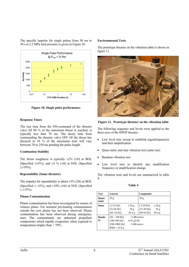
Single Pulse Performance
In the operation of the PRISMA thrusters mostly single pulses will be fired.
During the mission the pulse length will increased to compensate the decreasing thrust (corresponding to the feed pressure blow down) thus maintaining the required impulse bit. This is a more efficient way of using propellant than to fire several shorter pulses.
Anflo 6 21st Annual AIAA/USU Conference on Small Satellites
The specific impulse for single pulses from 50 ms to 30 s at 2.2 MPa feed pressure is given in Figure 10.
Single Pulse Performance@ Pfeed = 22 Bar
0
500
1000
1500
2000
2500
0,01 0,1 1 10 100FCV CMD Duration (s)
Isp
Ns/
kg
Figure 10. Single pulse performance
Response Times
The rise time from the ON-command of the thruster valve till 90 % of the maximum thrust is reached, is typically less than 70 ms. The decay time from commanding the thruster valve OFF till the thrust has decayed to 10 % of the maximum trust will vary between 70 to 250 ms pending the pulse length.
Combustion Stability
The thrust roughness is typically ±2% (1σ) at BOL (Specified ≤±5%), and ±3 % (1σ) at EOL (Specified ≤±10%).
Repeatability (Same thruster)
The impulse bit repeatability is about ±3% (2σ) at BOL (Specified ≤ ±5%), and ±10% (1σ) at EOL (Specified ≤ ±15%).
Plume Contamination
Plume contamination has been investigated by means of witness plates. For nominal pre-heating contamination outside the core plume has not been observed. Plume contamination has been observed during emergency start. The contaminants are unburned propellant components which rapidly evaporates when exposed to temperatures higher than + 70ºC.
Environmental Tests
The prototype thruster on the vibration table is shown in figure 11.
Figure 11. Prototype thruster on the vibration table
The following sequence and levels were applied to the three axes of the HPGP thruster.
• Low level sine sweep to establish eigenfrequencies and their amplification
• Quasi static and sine vibration test (same run)
• Random vibration test
• Low level sine to identify any modification frequency or amplification change
The vibration tests and levels are summarized in table 4.
Table 4
Test Lateral Longitudal
Quasi static
20 g 20 g
Sinus [ 5-21 Hz] 1-20 g [21-60 Hz] 20 g [60- 64 Hz] 20-6 g
[ 5-20 Hz] 1-20 g [21-60 Hz] 20 g [60-64 Hz] 20-6 g
Random
[20 – 100 Hz] +3 dB/octave [100-300 Hz] 0.91 g2/Hz [300-2000 Hz] -5 dB/octave RMS = 22.8 g
Anflo 7 21st Annual AIAA/USU Conference on Small Satellites
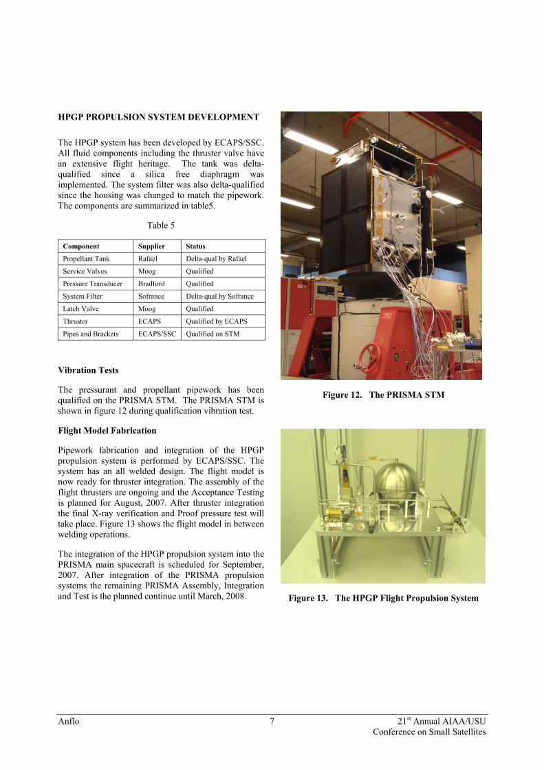
HPGP PROPULSION SYSTEM DEVELOPMENT The HPGP system has been developed by ECAPS/SSC. All fluid components including the thruster valve have an extensive flight heritage. The tank was delta-qualified since a silica free diaphragm was implemented. The system filter was also delta-qualified since the housing was changed to match the pipework. The components are summarized in table5.
Table 5
Component Supplier Status
Propellant Tank Rafael Delta-qual by Rafael
Service Valves Moog Qualified
Pressure Transducer Bradford Qualified
System Filter Sofrance Delta-qual by Sofrance
Latch Valve Moog Qualified
Thruster ECAPS Qualified by ECAPS
Pipes and Brackets ECAPS/SSC Qualified on STM
Vibration Tests
The pressurant and propellant pipework has been qualified on the PRISMA STM. The PRISMA STM is shown in figure 12 during qualification vibration test.
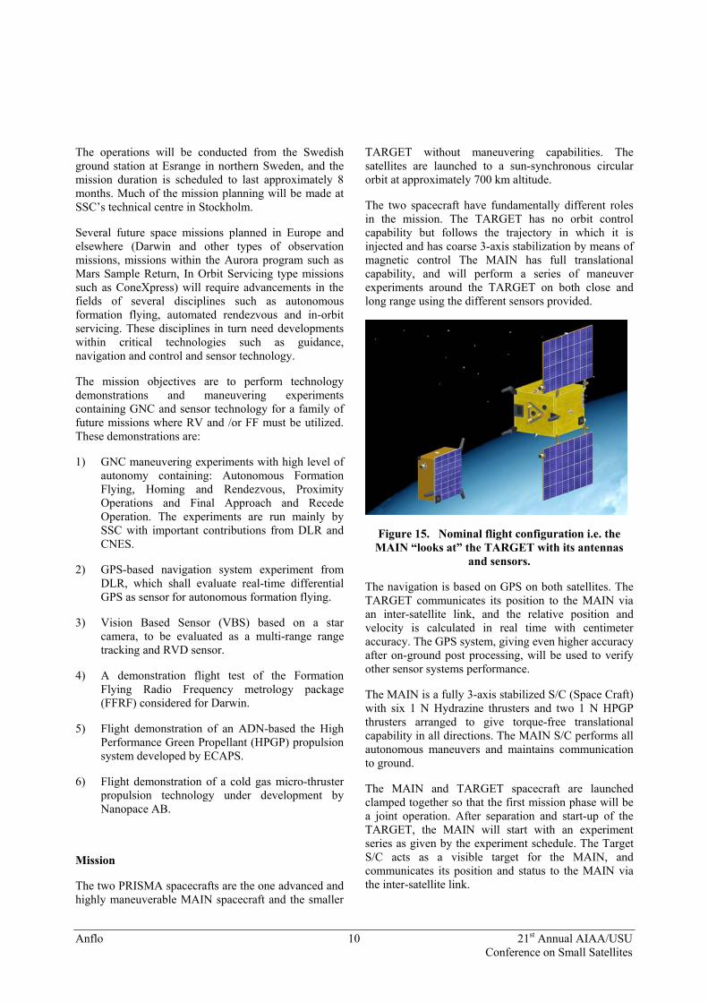
Flight Model Fabrication
Pipework fabrication and integration of the HPGP propulsion system is performed by ECAPS/SSC. The system has an all welded design. The flight model is now ready for thruster integration. The assembly of the flight thrusters are ongoing and the Acceptance Testing is planned for August, 2007. After thruster integration the final X-ray verification and Proof pressure test will take place. Figure 13 shows the flight model in between welding operations.
The integration of the HPGP propulsion system into the PRISMA main spacecraft is scheduled for September, 2007. After integration of the PRISMA propulsion systems the remaining PRISMA Assembly, Integration and Test is the planned continue until March, 2008.
Figure 12. The PRISMA STM
Figure 13. The HPGP Flight Propulsion System

Anflo 8 21st Annual AIAA/USU Conference on Small Satellites
PROPELLANT DEVELOPMENT LMP-103S The Ammonium Dinitramide (ADN) based monopropellant LMP-103S is a blend of ADN (NH4N(NO2)2), water, methanol and ammonia. ADN is the oxidizer which is dissolved in water with methanol and ammonia as fuel components, where ammonia also acts as a stabilizer. As previously mentioned, the performance and chemical/physical properties of the propellant depend on the composition. While different ADN-based propellant blends giving higher performance have been tested, LMP-103S is chosen for the PRISMA mission since this blend satisfies the other requirements for the PRISMA mission and the development performed for ESA.
Figure 14 shows the pilot plant for propellant manufacturing that has been built up by ECAPS and Eurenco-Bofors in Karlskoga. The plant is now operational and is producing flight quality LMP-103S. The facility is operated by Eurenco-Bofors who is also the manufacturer of ADN.
Figure 14. LMP-103S Propellant Plant
Extensive testing and evaluation of propellant LMP-103S has been performed regarding:
1) Performance
2) Safety
3) Storability
4) Purity
5) Compatibility
6) Temperature stability range
7) Radiation
Safety
Extensive safety related testing has been performed since 1998, as LMP-103S essentially is a premixed bi-propellant (fuel mixed with oxidizer) with high energy content. It is important to determine during which conditions the energy is released. Transport and handling of the propellant from the production site to the launch site is considered as one of the possible hazardous operations. A UN transport classification is therefore required before transport can be made. After successful testing, LMP-103S in its shipping container was classified to UN 1.4S by the Swedish authorities in 2006.
Additional safety test have been performed since the UN Classification only shows how the propellant behaves when kept in its approved shipping container. At the test range or at the launch site, when transferred to the fueling system and later to the satellite, confined in e.g. metal vessels, the behavior might be much different. Heated by an external fire, for example, under such conditions might trigger an explosion.
Extensive testing has therefore been performed to assure a safe system design and operation, and to establish the required knowledge for mitigation of any possible hazard. The tests have been performed Swedish Defense Research Agency (FOI). Eurenco- Bofors, and LIAB. The results from these tests are summarized below:
Tests have shown that the propellant is insensitive to hammering and friction.
Flammability tests show that it is difficult to ignite the propellant with an open flame.
Detonation test DN50 has shown that a shock wave from a detonation charge in direct contact with the propellant will cause a detonation in large containers.
The sensitivity for detonation of the propellant has been tested with Large Scale Gap Test (LSGT) and the results show a detonation sensitivity value of less than 70 cards, which indicate that it can be classified as a Class 1.3 substance (more than 70 cards is regarded as a Class 1.1 mass explosive).
Test of the critical diameter, the largest diameter of a tube filled with propellant at which steady-state detonation cannot be maintained, has been completed. Stainless steel (SS 316L) tubing with 1-2 mm wall thickness was used for the tests and a small booster charge was used to initiate the sample. It was found that

Anflo 9 21st Annual AIAA/USU Conference on Small Satellites
a detonation could not be maintained in tubing with an inner diameter of 10 mm and smaller.
Propellant LMP-103S is much less toxic than hydrazine and normal personal protective work clothing (simple splash-suit when handling larger quantities), gloves and eye protection (working in a fume-hood when handling open containers) is sufficient. However, since the propellant contains some methanol (especially toxic when digested), the hazard symbol labeling of the propellant needs to be a toxic and explosive substance. All subcomponents of the propellant are biodegradable, but it should anyway be properly destroyed by a certified company because of its energetic nature. LMP-103S is regarded as environmentally benign.
Storability
Storability tests of propellant LMP-103S have been performed by different methods. Storage for >1 year in glass containers at +20 and +60 ˚C indicates long term storability. Testing at +80˚C according to NATO standard STANAG 4582 (test standard fully applicable only on nitrate ester propellants) indicates that LMP-103S is storable >20 years within its operating temperature.
Ongoing End-to-End tests with a simplified version of satellite propulsion system have been running for more than 18 months where no degradation of the propellant or pressure build-up has been observed. This demonstrates that LMP-103S can be stored for longer periods in contact with COTS components,
Unlike hydrazine, LMP-103S is not sensitive to water residuals.
Purity
Impurities in the ADN, mainly Non Volatile Residues (NVR), have previously been the major reason for degradation of the performance and life of the thruster, causing poisoning of the catalyst and clogging of the nozzle. Extensive R&D work at EURENCO Bofors, the manufacturer of ADN, has successfully reduced the impurities from close to percent levels, down to low ppm levels (compatible with high purity hydrazine). By performing hot firing test with 1 N development thrusters it has been has been verified that the propellant meets the PRISMA and ESA flight quality requirements. With High Purity Grade LMP-103S propellant there is no indication of degradation of performance due to NVR.
Compatibility
Compatibility testing has been performed with LMP-103S and all wetted materials that are used in the propulsion system (made from hydrazine COTS components). For the metals, these tests include general corrosion, redox potential, galvanic corrosion, microcalorimetric testing, etc. Several propellant tank diaphragm rubbers have been investigated to determine if LMP-103S leaches out silica or other elements from the polymer, which may degrade the thruster. The materials of the selected COTS components have been verified to be compatible with the propellant.
Temperature stability range
The nominal operating temperature for LMP-103S is LMP-103S is +10 to +50˚C. Below -7˚C the propellant partially solidifies, but it also readily goes back to its liquid state when heated above -7˚C. A temperature of ca +120 ˚C is considered to be upper short term (hours) stability limit and further up the “onset” temperature is found at ca. +165˚C.
Radiation
The propellant has been exposed to 100 kRad with Cobalt 60 source to investigate its sensitivity to radiation. There was no indication of degradation after the radiation test.
PRISMA PRISMA is a technology mission for demonstrating formation flying and rendezvous technologies [2]. The PRISMA mission has been developed by the Swedish Space Corporation who is also the prime contractor. The project is funded by the Swedish National Space Board (SNSB), and is supported by in-kind contributions from the German Aerospace Centre (DLR), the French space agency (CNES) and the Danish Technical University. The primary goals are to perform Guidance, Navigation and Control (GNC) demonstrations and sensor technology experiments for a family of future missions where rendezvous and formation flying are a necessary prerequisite. The GNC demonstrations are: Autonomous Formation Flying, Homing and Rendezvous, Proximity Operations and Final Approach and Recede Operations. The sensor technologies are GPS, RF metrology and star tracker based vision sensors. A high level of autonomy shall be implemented. The mission consists of two spacecraft, one advanced and highly maneuverable MAIN spacecraft and a simplified TARGET satellite without maneuverability. Both spacecraft will be launched clamped together into a sun-synchronous orbit at around 700 km altitude. The launch of PRISMA is scheduled for 2009 on a Dnepr Launch vehicle from Baikanour.
Anflo 10 21st Annual AIAA/USU Conference on Small Satellites
The operations will be conducted from the Swedish ground station at Esrange in northern Sweden, and the mission duration is scheduled to last approximately 8 months. Much of the mission planning will be made at SSC’s technical centre in Stockholm.
Several future space missions planned in Europe and elsewhere (Darwin and other types of observation missions, missions within the Aurora program such as Mars Sample Return, In Orbit Servicing type missions such as ConeXpress) will require advancements in the fields of several disciplines such as autonomous formation flying, automated rendezvous and in-orbit servicing. These disciplines in turn need developments within critical technologies such as guidance, navigation and control and sensor technology.
The mission objectives are to perform technology demonstrations and maneuvering experiments containing GNC and sensor technology for a family of future missions where RV and /or FF must be utilized. These demonstrations are:
1) GNC maneuvering experiments with high level of autonomy containing: Autonomous Formation Flying, Homing and Rendezvous, Proximity Operations and Final Approach and Recede Operation. The experiments are run mainly by SSC with important contributions from DLR and CNES.
2) GPS-based navigation system experiment from DLR, which shall evaluate real-time differential GPS as sensor for autonomous formation flying.
3) Vision Based Sensor (VBS) based on a star camera, to be evaluated as a multi-range range tracking and RVD sensor.
4) A demonstration flight test of the Formation Flying Radio Frequency metrology package (FFRF) considered for Darwin.
5) Flight demonstration of an ADN-based the High Performance Green Propellant (HPGP) propulsion system developed by ECAPS.
6) Flight demonstration of a cold gas micro-thruster propulsion technology under development by Nanopace AB.
Mission
The two PRISMA spacecrafts are the one advanced and highly maneuverable MAIN spacecraft and the smaller
TARGET without maneuvering capabilities. The satellites are launched to a sun-synchronous circular orbit at approximately 700 km altitude.
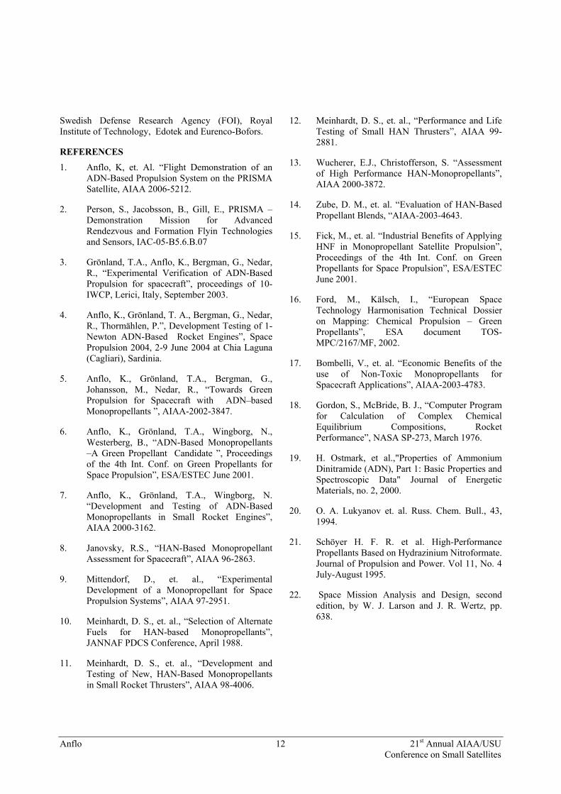
The two spacecraft have fundamentally different roles in the mission. The TARGET has no orbit control capability but follows the trajectory in which it is injected and has coarse 3-axis stabilization by means of magnetic control The MAIN has full translational capability, and will perform a series of maneuver experiments around the TARGET on both close and long range using the different sensors provided.
Figure 15. Nominal flight configuration i.e. the MAIN “looks at” the TARGET with its antennas
and sensors.
The navigation is based on GPS on both satellites. The TARGET communicates its position to the MAIN via an inter-satellite link, and the relative position and velocity is calculated in real time with centimeter accuracy. The GPS system, giving even higher accuracy after on-ground post processing, will be used to verify other sensor systems performance.
The MAIN is a fully 3-axis stabilized S/C (Space Craft) with six 1 N Hydrazine thrusters and two 1 N HPGP thrusters arranged to give torque-free translational capability in all directions. The MAIN S/C performs all autonomous maneuvers and maintains communication to ground.
The MAIN and TARGET spacecraft are launched clamped together so that the first mission phase will be a joint operation. After separation and start-up of the TARGET, the MAIN will start with an experiment series as given by the experiment schedule. The Target S/C acts as a visible target for the MAIN, and communicates its position and status to the MAIN via the inter-satellite link.

Anflo 11 21st Annual AIAA/USU Conference on Small Satellites
Spacecraft Design
The MAIN S/C layout is depicted in figure 16. The size is approximately 700x700x1000 mm. The S/C masses are approximately 150 kg for the MAIN and 50 kg for the TARGET.
The body has two deployable solar panels. The TARGET separation system is also located on the top face to meet the accommodation requirements of the launcher.
The attitude control system is based on reaction wheels, star trackers, and the vision based sensor. It can provide celestially based attitude control for TARGET spacecraft pointing or earth surface tracking as well as relative attitude control based on the vision based sensor.
The angular momentum is managed through a magnetic torque-rod system. The spacecraft also has sun sensors with full sphere detection capability. Orbit control is achieved with the use of the RCS with support from accelerometer measurements. The spacecraft has the capability to achieve a delta-V in any direction regardless of its attitude. The MAIN S/C is equipped with three propulsion systems.
Figure 16. The PRISMA Main Satellite Layout
PRISMA PROPULSION SYSTEMS The MAIN S/C propulsion systems are the:
1) Hydrazine RCS
2) HPGP RCS
3) MEMS-based Micro-propulsion System
The Hydrazine and HPGP propulsion systems provide the MAIN S/C with the required delta-V capabilities to be used for the various experiment described above. The Hydrazine RCS is the MAIN platform propulsion system while the HPGP system is a flight demonstrator in itself, but will also contribute with delta-V capability to the mission. The total delta-V capability of the PRISMA propulsion is ~170 m/s, which is more than two times the mission requirement. The two propulsion systems are planned to be operated separately but can be also be operated simultaneously, which adds redundancy. The thrust vectors are directed towards the COG of the S/C and are located such that torque-free motion can be created in all directions. Potential misalignment of the thrusters can be compensated with the reaction wheel torque. None of the thrusters are pointing directly in the rendezvous direction.
The micro-propulsion is based on Micro-Electro-Mechanical System (MEMS) technology and use compressed nitrogen as propellant. The two thruster pods contain four thrusters each. The micro-propulsion technology development is performed by Nanopace AB.
CONCLUSIONS The test firing of the flight prototype thruster demonstrates that the performance improvement is 25 to 30 % higher w.r.t. density impulse as compared to hydrazine. This put the HPGP delta-V capability between hydrazine and storable bipropellant systems for the same size tank but without increasing complexity and cost.
The development of the HPGP technology has progressed successfully. The validation required before the integration into the PRISMA main spacecraft is under finalization.
It is concluded that the ECAPS HPGP propulsion system is well on its way for a first flight demonstration of a new “Green” or “Reduced Hazard” storable monopropellant.
ACKNOWLEDGMENTS This work has been performed under contract from the Swedish National Space Board (SNSB). The authors acknowledge the sustained support from SNSB and ESA. The authors also acknowledge the strong support from the management and the effort of all co-workers in this project from ECAPS, Swedish Space Corporation,
Anflo 12 21st Annual AIAA/USU Conference on Small Satellites
Swedish Defense Research Agency (FOI), Royal Institute of Technology, Edotek and Eurenco-Bofors.
REFERENCES 1. Anflo, K, et. Al. “Flight Demonstration of an
ADN-Based Propulsion System on the PRISMA Satellite, AIAA 2006-5212.
2. Person, S., Jacobsson, B., Gill, E., PRISMA – Demonstration Mission for Advanced Rendezvous and Formation Flyin Technologies and Sensors, IAC-05-B5.6.B.07
3. Grönland, T.A., Anflo, K., Bergman, G., Nedar, R., “Experimental Verification of ADN-Based Propulsion for spacecraft”, proceedings of 10-IWCP, Lerici, Italy, September 2003.
4. Anflo, K., Grönland, T. A., Bergman, G., Nedar, R., Thormählen, P.”, Development Testing of 1-Newton ADN-Based Rocket Engines”, Space Propulsion 2004, 2-9 June 2004 at Chia Laguna (Cagliari), Sardinia.
5. Anflo, K., Grönland, T.A., Bergman, G., Johansson, M., Nedar, R., “Towards Green Propulsion for Spacecraft with ADN–based Monopropellants ”, AIAA-2002-3847.
6. Anflo, K., Grönland, T.A., Wingborg, N., Westerberg, B., “ADN-Based Monopropellants –A Green Propellant Candidate ”, Proceedings of the 4th Int. Conf. on Green Propellants for Space Propulsion”, ESA/ESTEC June 2001.
7. Anflo, K., Grönland, T.A., Wingborg, N. “Development and Testing of ADN-Based Monopropellants in Small Rocket Engines”, AIAA 2000-3162.
8. Janovsky, R.S., “HAN-Based Monopropellant Assessment for Spacecraft”, AIAA 96-2863.
9. Mittendorf, D., et. al., “Experimental Development of a Monopropellant for Space Propulsion Systems”, AIAA 97-2951.
10. Meinhardt, D. S., et. al., “Selection of Alternate Fuels for HAN-based Monopropellants”, JANNAF PDCS Conference, April 1988.
11. Meinhardt, D. S., et. al., “Development and Testing of New, HAN-Based Monopropellants in Small Rocket Thrusters”, AIAA 98-4006.
12. Meinhardt, D. S., et. al., “Performance and Life Testing of Small HAN Thrusters”, AIAA 99-2881.
13. Wucherer, E.J., Christofferson, S. “Assessment of High Performance HAN-Monopropellants”, AIAA 2000-3872.
14. Zube, D. M., et. al. “Evaluation of HAN-Based Propellant Blends, “AIAA-2003-4643.
15. Fick, M., et. al. “Industrial Benefits of Applying HNF in Monopropellant Satellite Propulsion”, Proceedings of the 4th Int. Conf. on Green Propellants for Space Propulsion”, ESA/ESTEC June 2001.
16. Ford, M., Kälsch, I., “European Space Technology Harmonisation Technical Dossier on Mapping: Chemical Propulsion – Green Propellants”, ESA document TOS-MPC/2167/MF, 2002.
17. Bombelli, V., et. al. “Economic Benefits of the use of Non-Toxic Monopropellants for Spacecraft Applications”, AIAA-2003-4783.
18. Gordon, S., McBride, B. J., “Computer Program for Calculation of Complex Chemical Equilibrium Compositions, Rocket Performance”, NASA SP-273, March 1976.
19. H. Ostmark, et al.,"Properties of Ammonium Dinitramide (ADN), Part 1: Basic Properties and Spectroscopic Data" Journal of Energetic Materials, no. 2, 2000.
20. O. A. Lukyanov et. al. Russ. Chem. Bull., 43, 1994.
21. Schöyer H. F. R. et al. High-Performance Propellants Based on Hydrazinium Nitroformate. Journal of Propulsion and Power. Vol 11, No. 4 July-August 1995.
22. Space Mission Analysis and Design, second edition, by W. J. Larson and J. R. Wertz, pp. 638.