Embed Size (px)
Citation preview
____________________________________________ * Electrical Engineer, Propulsion and Propellants Branch, 21000 Brookpark Rd. M/S 301-3, Associate Fellow
† Aerospace Engineer, 6002 Fleet Ave, Suite 100
1
American Institute of Aeronautics and Astronautics
NEXT Thruster Component Verification Testing
Luis R. Piñero*
NASA Glenn Research Center, Cleveland, Ohio 44135
and
James S. Sovey†
Alphaport Inc., Cleveland, Ohio 44135
Component testing is a critical part of thruster life validation activities under NASA’s
Evolutionary Xenon Thruster (NEXT) project testing. The high voltage propellant isolators
were selected for design verification testing. Even though they are based on a heritage
design, design changes were made because the isolators will be operated under different
environmental conditions including temperature, voltage, and pressure. The life test of two
NEXT isolators was therefore initiated and has accumulated more than 10,000 hrs of
operation. Measurements to date indicate only a negligibly small increase in leakage
current. The cathode heaters were also selected for verification testing. The technology to
fabricate these heaters, developed for the International Space Station plasma contactor
hollow cathode assembly, was transferred to Aerojet for the fabrication of the NEXT
prototype model ion thrusters. Testing the contractor-fabricated heaters is necessary to
validate fabrication processes for high reliability heaters. This paper documents the status
of the propellant isolator and cathode heater tests.
I. Introduction ASA Glenn Research Center (GRC) is developing the next generation ion propulsion system with higher power
and greater xenon throughput capability than that of the NASA Solar Electric Propulsion Technology
Applications Readiness (NSTAR) system that was successfully flown on the Deep Space 1 mission.1 This new
system is called NASA’s Evolutionary Xenon Thruster (NEXT), and it consists of a 36 cm beam diameter ion
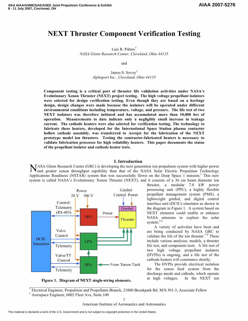
thruster, a modular 7.0 kW power
processing unit (PPU), a highly flexible
propellant management system (PMS), a
lightweight gimbal, and digital control
interface unit (DCIU) simulator as shown in
the diagram in Figure 1. A system based on
NEXT elements could enable or enhance
NASA missions to explore the solar
system.2-6
A variety of activities have been and
are being conducted by NASA GRC to
validate the life of the ion thruster.7-9
These
include various analyses, models, a thruster
life test, and component tests. A life test of
two high voltage propellant isolators
(HVPIs) is ongoing, and a life test of the
cathode heaters will commence shortly.
The HVPIs provide electrical isolation
for the xenon feed system from the
discharge anode and cathode, which operate
at high voltages. In the NEXT ion
N
43rd AIAA/ASME/SAE/ASEE Joint Propulsion Conference & Exhibit 8 - 11 July 2007, Cincinnati, OH
AIAA 2007-5276
This material is declared a work of the U.S. Government and is not subject to copyright protection in the United States.

2
American Institute of Aeronautics and Astronautics
propulsion system, these potentials can be as high as 1800 V from ground. The HVPIs were selected for life
validation because, even though there are based on a heritage design, they sustained enough design changes to
require validation.10-12
A life test of the NEXT HVPIs was deemed necessary because the NEXT design was
changed to accommodate higher operating voltages, the hardware was procured from a different manufacturer, and it
was necessary to verify the HVPIs could handle NEXT pressures and anticipated temperature requirements. Two
propellant isolators are under-going a life test under simulated environmental conditions of voltage, temperature,
and pressure. The primary objectives are to ensure that the design has sufficient voltage and temperature margin,
identify unexpected life-limiting phenomena, characterize the performance, and qualify the propellant isolator
design for full power operation of a NEXT ion engine for its life requirement. The test will continue for 20,000 hrs
or until the leakage current on the propellant isolators exceeds 100 !A. The upper bound on acceptable leakage
current is an extremely conservative requirement, and it was chosen to be the same as the requirement for NSTAR
HVPIs.13
Cathode heaters, developed for the International Space Station (ISS) plasma contactor hollow cathode
assembly, are used to raise the temperature of the emitters in the neutralizer and discharge hollow cathodes to the
level of thermionic emission during ignition.14-15
The NEXT neutralizer and discharge chamber cathodes use a
sheathed heater coiled on cathode tubes that have different diameters. The NEXT prototype model (PM) thruster,
including cathode heaters, was fabricated by Aerojet under contract with GRC. Aerojet heaters will be put through a
series of acceptance tests, including a bake-out, burn-in, and a current ramp-up test. The heaters will then be
subjected to a cyclic life test to evaluate reliability. This will validate the heater manufacturing and assembly
processes transferred to Aerojet from GRC.
This paper documents the test setups, test plans, test procedures, and results obtained to date for the HVPI and
cathode heater tests.
II. HVPI Apparatus
A. High-Voltage Propellant Isolators
The NEXT HVPI design concept is based on the NSTAR HVPI that was successfully tested at the component
and thruster level for 16,000 and 30,000 hours, respectively.11,16
The NSTAR HVPIs have segments to step-down a
potential to ground of about 1100 V. A maximum current leakage of 100 !A, from the thruster to spacecraft
ground, was specified in the NSTAR Thruster Element Requirements Document.13
However, higher currents to
spacecraft could be tolerated. The current leakage specification could be increased by an order of magnitude since
the maximum power loss in this case would only be about 1 W, and the impact on thruster performance would be
negligible. Evaluations of NSTAR flight-type propellant
isolator current leakage during ground tests and a flight
test indicate isolator materials, joining methods, and test
environment pose no threat to very long-life
operation.1,11,16
The NEXT HVPIs provide electrical isolation of the
gas feed system at ground potential from the ion engine
hollow cathode and discharge chamber, which can be at a
potential of 1800 V above ground. The isolators were
made of nickel-alloy housing flanges, an alumina housing,
and backup alumina rings.17
The braze is oxygen free, high
conductivity copper. The HVPI has shields to prevent
line-of-sight deposition of sputtered efflux or external
contaminants. Shields are used because surface coatings
on the HVPI alumina housing can cause unwanted current
leakage from high voltage to ground. A photograph of the
HVPIs is shown in Figure 2.
Voltage breakdown tests of a HVPI of nearly identical design indicated that the Paschen minimum breakdown
voltage was about 4000 V.12
The Paschen minimum is the worst-case breakdown-voltage for an isolator
configuration with xenon gas. Tests at NASA GRC showed that the HVPI under test had a minimum breakdown
voltage in excess of 2300 V. Testing at higher voltages was not done to minimize risk to the HVPI test article. In
the NEXT ion engine, the propellant isolator is usually operated at 1800 V or less so there is at least 500 V margin
relative to the Paschen minimum voltage, and margin could be as high as 2200 V based on the results of Ref. 12.
Figure 2. HVPIs for the design verification test.

3
American Institute of Aeronautics and Astronautics
In addition to having a much higher voltage capability compared to the NSTAR HVPI, the NEXT HVPI design
has a smaller radial envelope than the NSTAR unit. The smaller diameter reduces mass and mitigates risk
associated with vibration environments.
B. Test Setup
The test is being performed in GRC’s Vacuum Facility 62. A block diagram and a photograph of the test setup
for the HVPI design verification testing are shown in Figures 3 and 4, respectively. The cryogenically pumped
vacuum chamber is 30 cm in diameter and 76 cm long. An oil-free roughing pump is used in conjunction with a
cryogenic pump, which has a pumping speed of 2100 l/s. The typical operating pressure is 0.1 mPa. The pressure in
the vacuum chamber is very low because the xenon flow through the HVPIs does not exhaust into the chamber but
is plumbed through the chamber flange to an auxiliary scroll pump that maintains a pressure of about 38 Pa at the
HVPI exit. Capacitance manometer
pressure gages are mounted upstream and
downstream of the isolators. A flow
control valve upstream of the isolators and
external to the vacuum chamber controls
fine adjustment of the pressure at the
isolators.
The isolators are heated by using four
tungsten-halogen lamps with facility
radiation shields placed appropriately to
minimize local heating of the vacuum
chamber. The HVPIs have a primary
thermocouple placed on tubing about 2 cm
from the downstream flange of one of the
HVPIs. A second thermocouple is located
between the radiation shields and is used to
control the power to the lamps by means of
an industrial temperature controller. After
a few tests, this thermocouple arrangement
was found to reduce the noise in the
metered HVPI leakage current.
A laboratory power supply provides
high voltage across the isolators. Leakage
4
American Institute of Aeronautics and Astronautics
currents are measured by an electrometer with the capability to measure less than a nanoampere. Current data are
taken every minute and stored by the electrometer. The operation of the electrometer is periodically checked using a
10 G" resistor and a separate voltage source.
III. HVPI Test Procedures A. Operating Parameters
1. Voltage
Many of the NEXT HVPI design and test decisions were based on the experiences with the NSTAR HVPIs.
The NSTAR HVPIs had an electrical breakdown limit of approximately 1700V. The maximum voltage across the
HVPIs was 1100 V. Voltage over-shoot during high voltage recycles using the flight power processor did not
exceed 5% of the maximum voltage value. HVPI component tests were conducted at 1300 V during the NSTAR
program.11
In this case the component test voltage margin was about 200 V higher than the worst-case NSTAR
thruster operating condition.
The estimated minimum breakdown voltage for the NEXT HVPIs is 4000 V based on the results of Ref. 12.
For the NEXT thruster, the maximum voltage across the HVPI is 1800 V. During tests of the NEXT breadboard
power processor, voltage over-shoot was less than 5% of the nominal voltage. It was decided that the HVPI
component test be conducted at 2300 V for a voltage margin of at least 500 V over the maximum voltage setpoint.
NSTAR and NEXT HVPI component test voltage margins of 200 V and 500 V, respectively, were somewhat
arbitrary, but these margins were factors of 3 to 5 higher than worst-case over-shoot voltages during high voltage
recycles of the grid system.
2. Temperature
For a point of reference, the NSTAR HVPI maximum temperature was 201 ˚C when the thruster was operated
at full power and surrounded by an adiabatic can.18
Also, thermal modeling predictions were made for the NSTAR
flight thruster running at maximum power of 2.3 kW. The environment was one-sun, 30o off-axis sun angle. In this
case, the HVPI temperature was estimated to be in the 200 - 206 ˚C range. The NSTAR HVPI maximum
temperature during component tests was 220 ˚C.
For the NEXT component tests, a HVPI reference temperature of 260 ˚C was selected. This HVPI reference
temperature is estimated to be about 40˚C higher than isolator temperatures for the NEXT EM thruster operated at
full power, without an adiabatic enclosure and without solar simulation. For example, Soulas (Ref. 19) has shown
the temperature of the upstream end of the cylindrical part of an EM thruster discharge chamber was about 265 ˚C
when operation was at full power without solar simulation. Since the HVPIs were mounted from brackets off the
discharge chamber, they were thermally decoupled from the anode to some extent. The HVPI temperature at these
conditions is estimated to be in the range of 200 to 220 ˚C.
Preliminary thermal model results predict that the anode of the NEXT Prototype Model (PM) thruster discharge
chamber will have a temperature about 75 ˚C cooler than the EM thruster when operated at full-power.20
Given these
temperature indications, it is estimated that the HVPI component test temperature of 260 ˚C would provide about 65
˚C margin for the PM thruster in the worst-case environment that included three operating thrusters in an adiabatic
enclosure, at 0.85 AU, and 38o off-axis sun angle.
21
3. Pressure
Measurements of the pressure upstream of HVPIs were made during the course of test of the NEXT EM
thruster.19
Typical HVPI upstream pressures were 2.4 kPa and 13.0 kPa for the hollow cathode and discharge
chamber feed lines, respectively. Given this information, the HVPI functional tests are planned to be carried out
periodically over a 1.3 kPa to 13.0 kPa range. The life test is being conducted at an upstream pressure of about 3.3
kPa. This lower pressure was selected to simulate the hollow cathode pressure environment at full power. The
xenon flow through the HVPIs is pumped through an auxiliary scroll pump that maintains a pressure of about 38 Pa
upstream of the pump.
B. Test Plan and Procedure
Short-term functional tests of the HVPIs were conducted at the beginning and will be conducted at the end of
the life test. The life validation test will be conducted for a period of 20,000 hours, which is the qualification-test
requirement for the NEXT thruster operating at full power.
The vacuum facility interior surfaces were cleaned with alcohol prior to bake-out runs with the laboratory-
class isolator. The laboratory-class propellant isolator was used in facility check-out tests and preliminary
performance tests. The results of this test refined the procedures for the test of the flight-like isolators. The xenon
5
American Institute of Aeronautics and Astronautics
flow rate was adjusted with flow control valves to provide an operating range of 1.3 kPa to 13.0 kPa upstream of the
HVPIs. Radiant heating was performed using closed-loop control on a reference thermocouple near the isolators.
The radiant power source and the high voltage power supplies were interlocked to shutdown when the indicated
facility pressure exceeded 670 !Pa.
The two NEXT HVPIs used in the design verification test are identical to the prototype ion engine isolators.17
The functional tests involve testing at temperatures of 100 ˚C to 260 ˚C, at voltages from 500 V to 2300 V, and
internal pressures in the range 1.3 kPa to 13.0 kPa.
During the life validation test, the temperature of the HVPIs is maintained at 260±5 ˚C, voltage is set to 2300 V,
and the downstream pressure is maintained at 2.7±0.3 kPa. Testing is initiated only if the facility pressure is below
270 !Pa. All test data are recorded once every 24 hours. Isolator leakage currents are monitored more frequently on
a data logger.
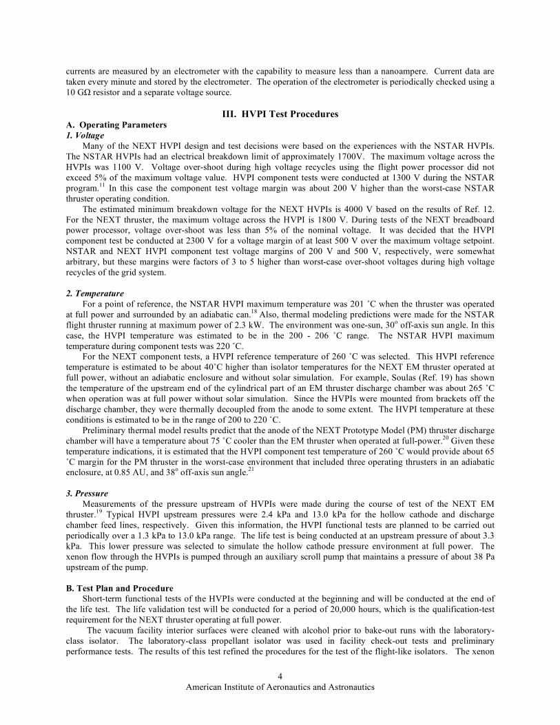
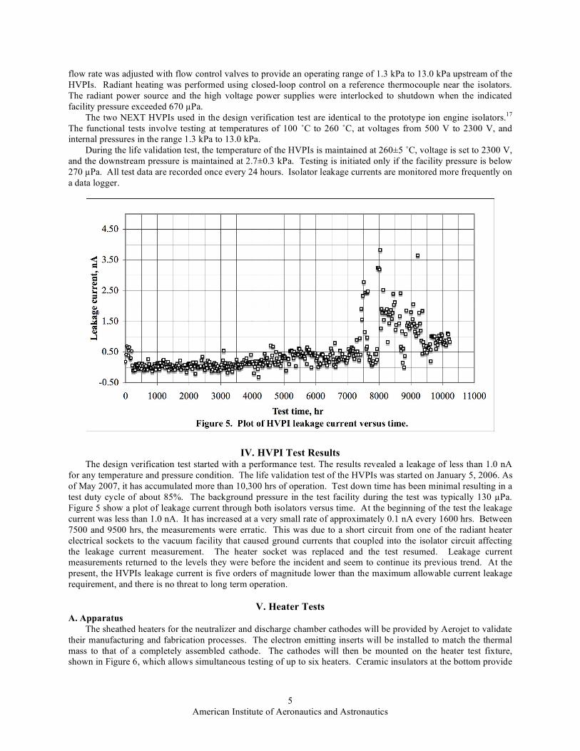
IV. HVPI Test Results
The design verification test started with a performance test. The results revealed a leakage of less than 1.0 nA
for any temperature and pressure condition. The life validation test of the HVPIs was started on January 5, 2006. As
of May 2007, it has accumulated more than 10,300 hrs of operation. Test down time has been minimal resulting in a
test duty cycle of about 85%. The background pressure in the test facility during the test was typically 130 !Pa.
Figure 5 show a plot of leakage current through both isolators versus time. At the beginning of the test the leakage
current was less than 1.0 nA. It has increased at a very small rate of approximately 0.1 nA every 1600 hrs. Between
7500 and 9500 hrs, the measurements were erratic. This was due to a short circuit from one of the radiant heater
electrical sockets to the vacuum facility that caused ground currents that coupled into the isolator circuit affecting
the leakage current measurement. The heater socket was replaced and the test resumed. Leakage current
measurements returned to the levels they were before the incident and seem to continue its previous trend. At the
present, the HVPIs leakage current is five orders of magnitude lower than the maximum allowable current leakage
requirement, and there is no threat to long term operation.
V. Heater Tests A. Apparatus
The sheathed heaters for the neutralizer and discharge chamber cathodes will be provided by Aerojet to validate
their manufacturing and fabrication processes. The electron emitting inserts will be installed to match the thermal
mass to that of a completely assembled cathode. The cathodes will then be mounted on the heater test fixture,
shown in Figure 6, which allows simultaneous testing of up to six heaters. Ceramic insulators at the bottom provide

6
American Institute of Aeronautics and Astronautics
electrical and thermal isolation against conducted heat. Stainless steel radiation shields provide protection from
radiated heat.
The test fixture will be installed in Vacuum Facility 65
at GRC. This is a 91 cm long by 48 cm diameter
cryogenically pumped belljar with a glass dome. The facility
is capable of a “no-load” pressure of 13 !Pa, corrected for
xenon. A photograph of the test facility is shown in Figure
7.
The heater test will be controlled by a data acquisition
and control system (DAC). A computer sends commands to
the heater power supplies through a multi-channel digital-to-
analog converter. Test data for each heater are sent to the
computer for display and storage through a multiplexer and
an analog-to-digital converter. Heater currents are measured
with isolated Hall effect sensors. Voltages are measured at
the vacuum feed through to eliminate voltage drops.
Finally, heater temperatures are measured with R-type
thermocouples. A block diagram on the test setup is shown
in Figure 8.
B. Test Plan and Procedure
The test sequence includes the
several tests. First, the heaters will
go through a bake-out to allow
outgassing. Then, they will be
subjected to a burn-in test and
subsequently a current ramp test.
These last two tests help assess
performance and unit-to-unit
repeatability. During the burn-in
test, the heaters are subjected to a
number of cycles (on for 6 minutes
and off for 4 minutes) operating at
8.50 A which is the current level
used for cathode ignition. During
the current ramp test, they are
operated with a current that slowly
increases from 0.00 to 8.50 A.
Finally, the heater will go into the
cyclic life test. This test is like the
burn-in; however, the heaters are
operated until they fail. The most
common failure mode is an open
circuit of the center conductor. The
cyclic life test is a worst-case test and
will subject the NEXT cathode heaters
to orders of magnitude more cycles
than required. The success criterion
for the cyclic life test is heaters that
meet or exceed the B10 lifetime of the
ISS plasma contactor hollow cathode
assembly. This is the statistical
number of cycles at which 10% of the
test heaters would fail after 6679
cycles.

7
American Institute of Aeronautics and Astronautics
Summary Life validation plans for the NEXT ion thruster include component verification testing. HVPIs were selected
for verification because even though they are based on previous designs, they will be operated in a significantly
different environment. Two HVPIs are currently undergoing a life validation test under worst-case test parameters
(plus margin) such as voltage, temperature, and pressure conditions. After more than 10,000 hrs of operation, only a
slight increase in leakage current has been detected. The leakage current is about 1 nA which is five orders of
magnitude lower than the 100 !A requirement. The cathode heaters for the NEXT thruster will also undergo a
series of acceptance tests and a cyclic life test to evaluate reliability. Successful completion of these tests will
ensure that these NEXT thruster components are of the expected quality and will also validate Aerojet’s
manufacturing processes.
References 1Polk, J. E., et al., “Demonstration of the NSTAR Ion Propulsion System on the Deep Space 1 Mission,” IEPC-01-
075, International Electric Propulsion Conference, October 2001. 2Benson, S. W., Patterson, M. J., Vaughan, D. A., Wilson, A. C., and Wong, B. R., “NASA’s Evolutionary Xenon
Thruster (NEXT) Phase 2 Development Status,” AIAA-2005-4070, Joint Propulsion Conference, July 2005. 3Piñero, L.R., Hopson, M., Todd, P., and Wong, B., “Performance of the NEXT Engineering Model Power
Processing Unit,” AIAA-2007-5214, Joint Propulsion Conference, July 2007. 4Aadland, R.S., Frederick, H., Benson, S.W., and Malone, S., “Development Results of the NEXT Propellant
Management System,” JANNAF Conference, 2005. 5Monheiser, J., Aadland, R., and Wilson, F., “Development of a Ground Based Digital Control Interface Unit
(DCIU) for the NEXT Propulsion System,” AIAA-2004-4112, Joint Propulsion Conference, July 2004. 6Snyder, J.S., O’Connell, M.R., Fernandez, J.P., Wang, G., McNabb, R.S., and Crumb, D., “Vibration Test of a
Breadboard Gimbal for the NEXT Ion Engine,” AIAA-2006-4665, Joint Propulsion Conference, July 2006. 7Soulas, G. C., et al., “NEXT Ion Engine 2000-Hour Wear Test Results,” AIAA-2004-3791, Joint Propulsion
Conference, July 2004. 8Herman, D. A., Soulas, G. C. and Patterson, M. J., “Status of the NEXT Ion Thruster Long Duration Test,” AIAA-
2007-5272, Joint Propulsion Conference, July 2007. 9Van Noord, J. and Williams, G. J., “Life Assessment of the NEXT Ion Thruster,” AIAA-2007-5274, Joint
Propulsion Conference, July 2007. 10
Mantenieks, M. A., “Status of 30-Centimeter-Diameter Mercury Ion Thruster Isolator Development,” NASA
TMX-73514, November 1976. 11
Sovey, J. S., Zakany, J. S., and Manzella, D. H., “NSTAR High Voltage Propellant Isolator Test,” NASA TM-
2004-212921, February 2004. 12
Hart, S. L., et al., “Investigation and Development of a High Voltage Propellant Isolator for Ion Thrusters,” IEPC-
2005-316, International Electric Propulsion Conference, October 2005. 13Hamley, J. A., NSTAR Thruster Element Technical Requirements Document, ND-310, JPL Report D-13638, April
1997. 14
Patterson, M. J., et al., “Space Station Cathode Design, Performance and Operating Specifications,” IEPC-97-170,
International Electric Propulsion Conference, August 1997. 15
Soulas, G. C., “Status of Hollow Cathode Heater Development for the Space Station Plasma Contactor,” AIAA-
94-3309, Joint Propulsion Conference, July 1994. 16
Sengupta, A., et al., “Status of the Extended Life Test of the Deep Space 1 Flight Spare Ion Engine After 30,352
Hours of Operation,” AIAA-2003-4558, Joint Propulsion Conference, July 2003. 17
Hoskins, W. A., et al., “Development of a Prototype Model Ion Thruster for the NEXT System,” AIAA-2004-
4111, Joint Propulsion Conference, July 2004. 18
Rawlin, V. K., et al., “NSTAR Flight Thruster Qualification Testing,” AIAA-98-3936, Joint Propulsion
Conference, July 1998. 19
Soulas, G. C., Domonkos, M. T. and Patterson, M. J., “Performance Evaluation of the NEXT Ion Engine,” AIAA-
2003-5278, Joint Propulsion Conference, July 2003. 20
Hoskins, W. A., Aerojet, Private Communication, November 2005. 21
Van Noord, J. L., “NEXT Ion Thruster Thermal Model,”AIAA-2007-5218, Joint Propulsion Conference, July
2007.