Embed Size (px)
Citation preview

July 2005 3-1
Prestressed Concrete Beam Design Workshop
Load and Resistance Factor Design
Flexure Design
Flexure Design Sequence
• Determine Effective flange width• Determine maximum tensile beam stresses
(without prestress)• Estimate eccentricity and number of strands
at midspan• Calculate prestress loss• Determine number of strands and develop
strand arrangement
Flexure Design Sequence
• Determine eccentricities• Check service stresses• Check fatigue• Calculate nominal flexural resistance• Check reinforcement limits• Determine pretensioned anchorage zone
reinforcement
July 2005 3-2
Example
Example 1
120'-0"
Example 1
Centerline bridge1'-0" 18'-0" 18'-0" 1'-0"
AASHTO Type VI Beam
4'-9" 9'-6" 4'-9" 4'-9" 9'-6" 4'-9"
9"
TYPICAL SECTION
July 2005 3-3
Example 1
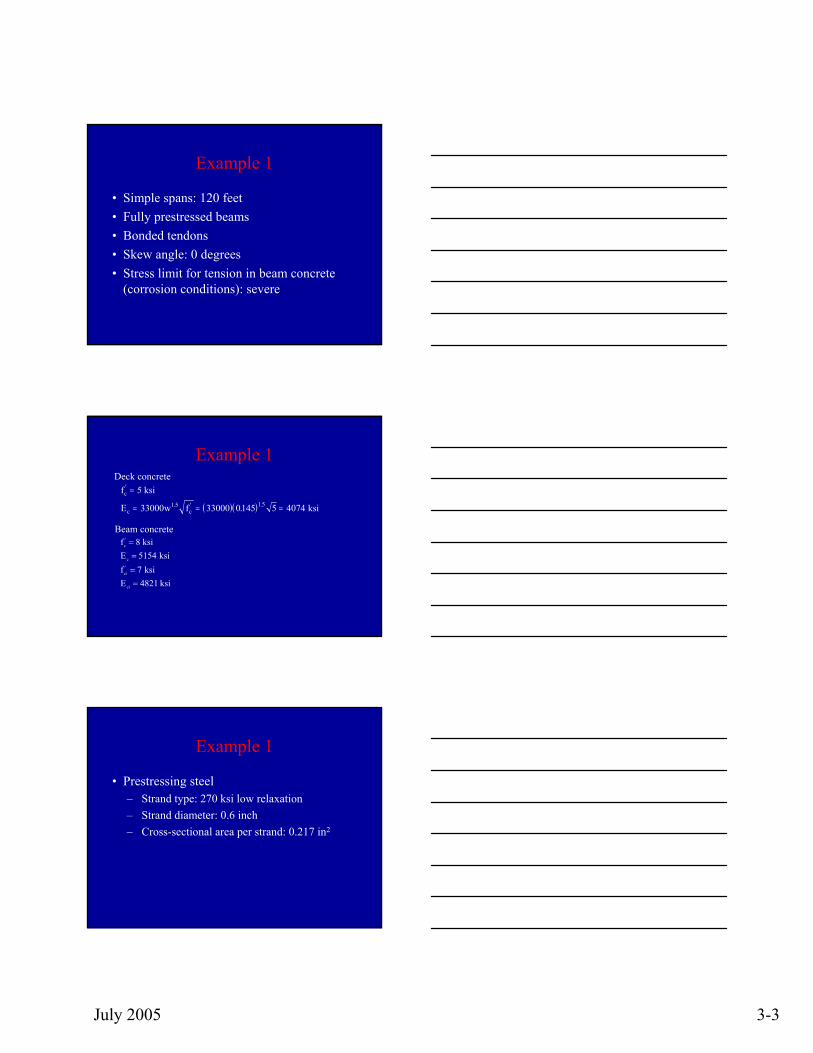
• Simple spans: 120 feet• Fully prestressed beams• Bonded tendons• Skew angle: 0 degrees• Stress limit for tension in beam concrete
(corrosion conditions): severe
Example 1Deck concrete
Beam concrete
( )( )
f
w f
c
c
'
. ' ..
=
= = =
5
33000 33000 0145 5 40741 5 1 5
ksi
E ksic
fc' ==
==
8515474821
ksiE ksif ksiE ksi
c
ci'
ci
Example 1
• Prestressing steel– Strand type: 270 ksi low relaxation– Strand diameter: 0.6 inch– Cross-sectional area per strand: 0.217 in2
July 2005 3-4
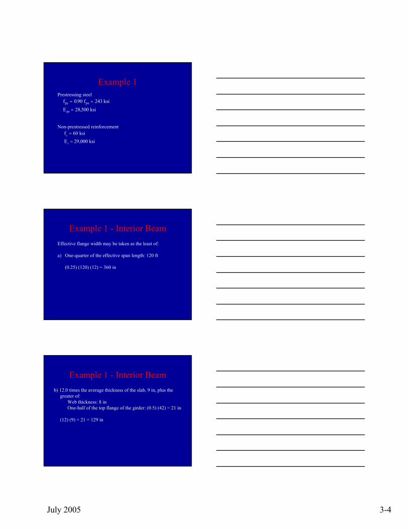
Example 1Prestressing steel
Non-prestressed reinforcementfy =
=
6029 000
ksiE ksis ,
fpy = =
=
0 90 243
28 500
.
,
f ksi
E ksipu
ps
Example 1 - Interior BeamEffective flange width may be taken as the least of:
a) One-quarter of the effective span length: 120 ft
(0.25) (120) (12) = 360 in
Example 1 - Interior Beamb) 12.0 times the average thickness of the slab, 9 in, plus the
greater of: Web thickness: 8 in One-half of the top flange of the girder: (0.5) (42) = 21 in
(12) (9) + 21 = 129 in
July 2005 3-5
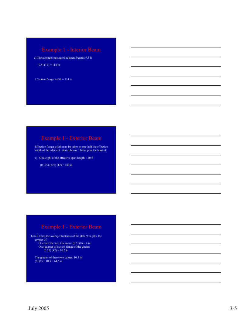
Example 1 - Interior Beamc) The average spacing of adjacent beams: 9.5 ft
(9.5) (12) = 114 in
Effective flange width = 114 in
Example 1 - Exterior BeamEffective flange width may be taken as one-half the effective width of the adjacent interior beam, 114 in, plus the least of:
a) One-eight of the effective span length: 120 ft
(0.125) (120) (12) = 180 in
Example 1 - Exterior Beamb) 6.0 times the average thickness of the slab, 9 in, plus the
greater of: One-half the web thickness: (0.5) (8) = 4 in One-quarter of the top flange of the girder:
(0.25) (42) = 10.5 in
The greater of these two values: 10.5 in(6) (9) + 10.5 = 64.5 in
July 2005 3-6
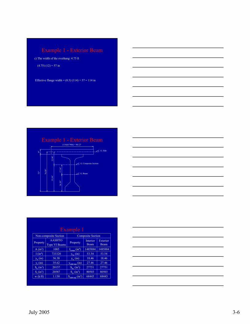
Example 1 - Exterior Beamc) The width of the overhang: 4.75 ft
(4.75) (12) = 57 in
Effective flange width = (0.5) (114) + 57 = 114 in
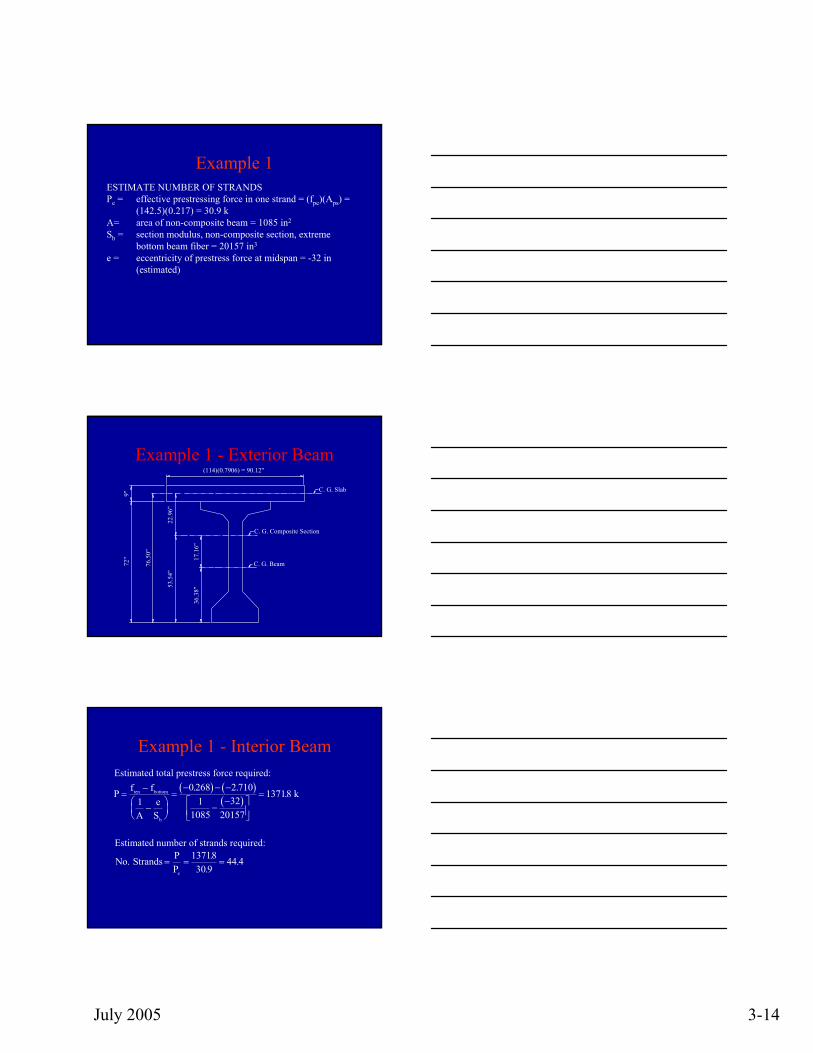
Example 1 - Exterior Beam(114)(0.7906) = 90.12"
C. G. Beam
C. G. Composite Section
53.5
4"
36.3
8"
C. G. Slab
72"
9"
76.5
0"
17.1
6"
22.9
6"
Example 1
68443 68443 Sslab top (in3)1.130w (k/ft)80503 80503 Stc (in3)20587St (in3)27751 27751 Sbc (in3)20157Sb (in3)27.46 27.46 yslab top (in)35.62yt (in)18.46 18.46 ytc (in)36.38yb (in)53.5453.54ybc (in)733320I (in4)
14858841485884Icomp (in4)1085A (in2)
Exterior Beam
Interior BeamProperty
AASHTO Type VI Beams
Property
Composite SectionNon-composite Section
July 2005 3-7
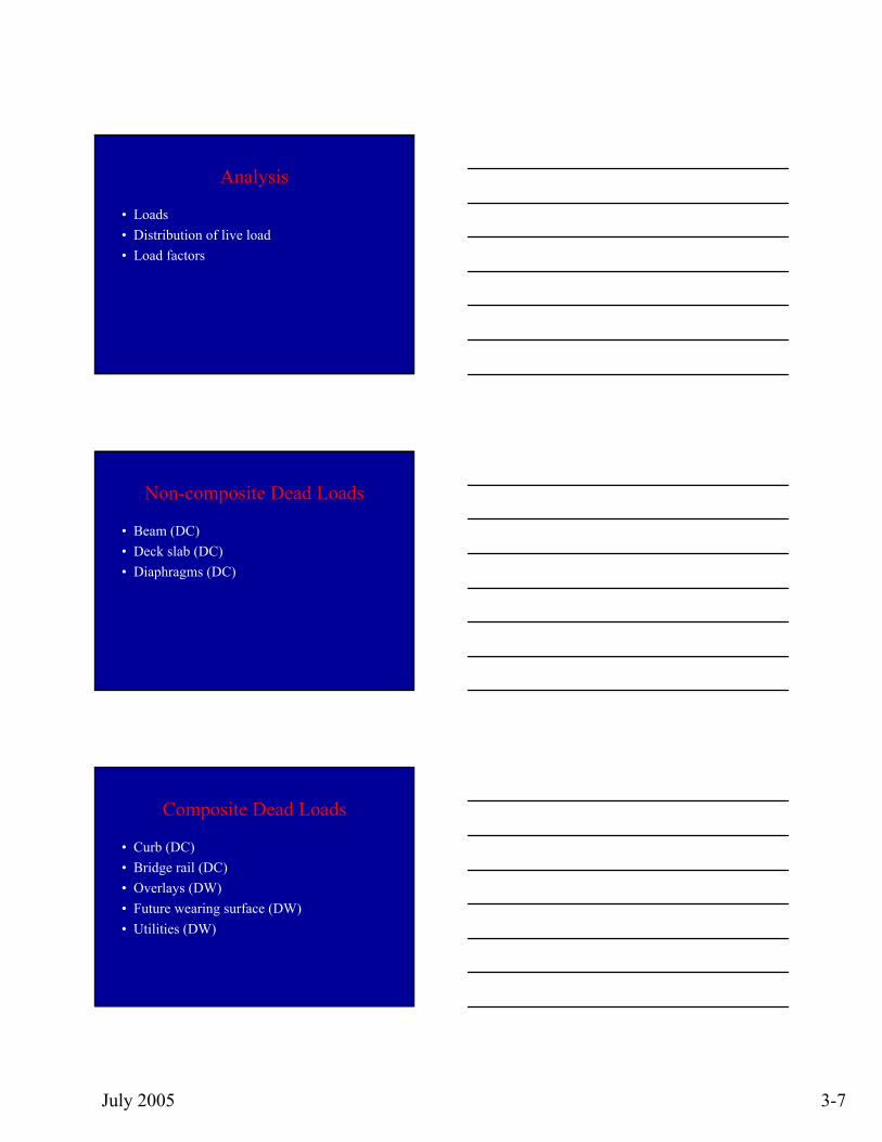
Analysis
• Loads• Distribution of live load• Load factors
Non-composite Dead Loads
• Beam (DC)• Deck slab (DC)• Diaphragms (DC)
Composite Dead Loads
• Curb (DC)• Bridge rail (DC)• Overlays (DW)• Future wearing surface (DW)• Utilities (DW)
July 2005 3-8
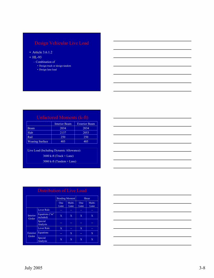
Design Vehicular Live Load
• Article 3.6.1.2• HL-93
– Combination of • Design truck or design tandem• Design lane load
Unfactored Moments (k-ft)
2053 2137Slab
405405Wearing Surface250250Rail
20342034BeamExterior BeamInterior Beam
Live Load (Including Dynamic Allowance):
3680 k-ft (Truck + Lane)
3080 k-ft (Tandem + Lane)
Distribution of Live LoadShearBending Moment
Multi-Lane
One Lane
Multi-Lane
One Lane
XXXXSpecial Analysis
X--X--Equations--X--XLever Rule
Exterior Girder
--------Special Analysis
XXXXEquations (“m”included)
--------Lever Rule
Interior Girder
July 2005 3-9
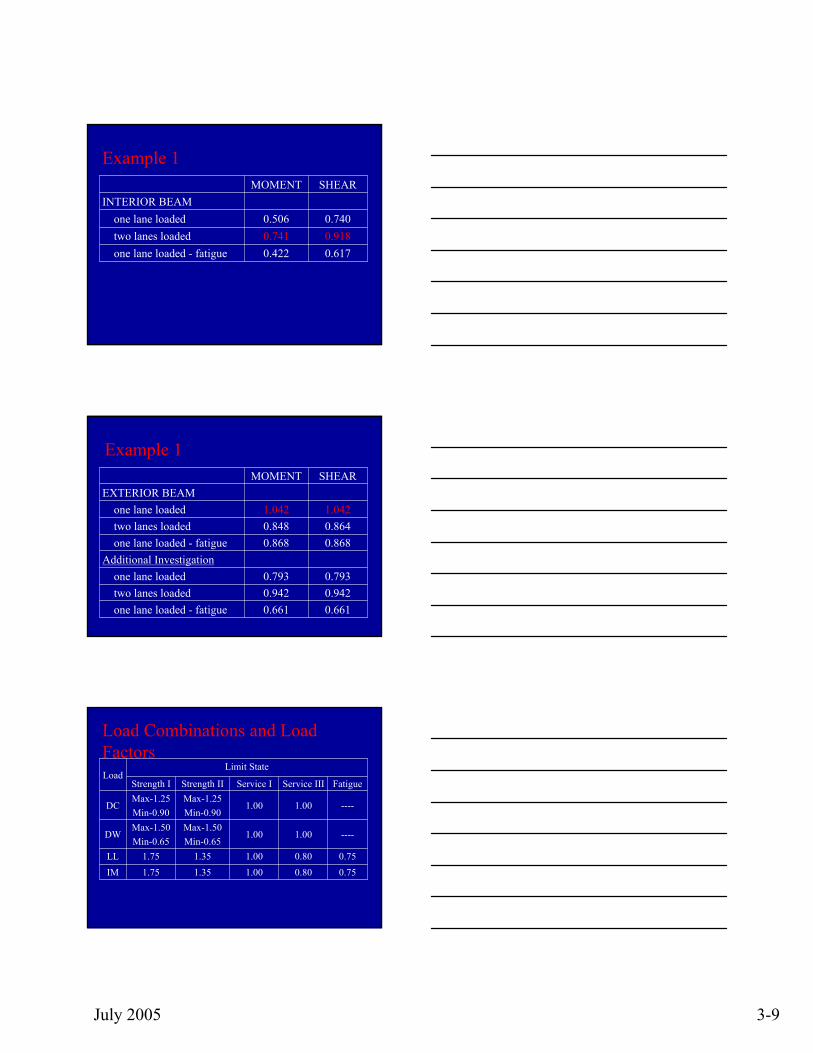
Example 1
0.6170.422one lane loaded - fatigue0.9180.741two lanes loaded 0.7400.506one lane loaded
INTERIOR BEAMSHEARMOMENT
Example 1
1.0421.042one lane loaded
0.6610.661one lane loaded - fatigue0.9420.942two lanes loaded 0.7930.793one lane loaded
Additional Investigation0.8680.868one lane loaded - fatigue0.8640.848two lanes loaded
EXTERIOR BEAMSHEARMOMENT
Load Combinations and Load Factors
0.750.801.001.351.75IM0.750.801.001.351.75LL
----1.001.00Max-1.50Min-0.65
Max-1.50Min-0.65
DW
----1.001.00Max-1.25Min-0.90
Max-1.25Min-0.90
DC
FatigueService IIIService IStrength IIStrength I
Limit StateLoad
July 2005 3-10
Beam Stresses
• Due to dead load and live load Service III limit state (Crack Control)
Service I limit state
fM M
SM M M
Sbottombeam slab
b
rail ws LL
bc= −
+−
+ + 08.
fM M
SM M M
Stopbeam slab
t
rail ws LL
tc=
++
+ +
Beam Stresses
Example 1
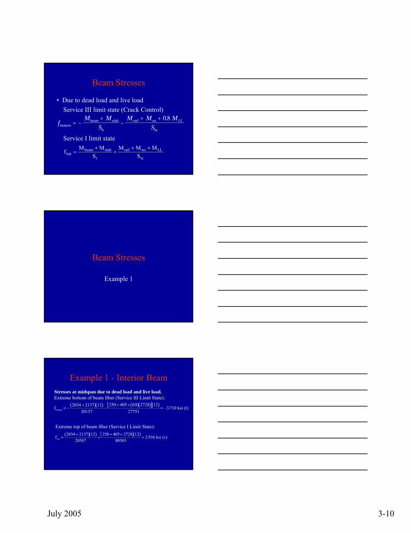
Example 1 - Interior BeamStresses at midspan due to dead load and live load.Extreme bottom of beam fiber (Service III Limit State):
( )( ) ( )( )[ ]( )fbottom = −+
−+ +
= −2034 2137 12
20157250 405 08 2728 12
277513710
.. ksi (t)
Extreme top of beam fiber (Service I Limit State):( )( ) [ ]( )ftop =
++
+ +=
2034 2137 1220587
250 405 2728 1280503
2 936. ksi (c)
July 2005 3-11
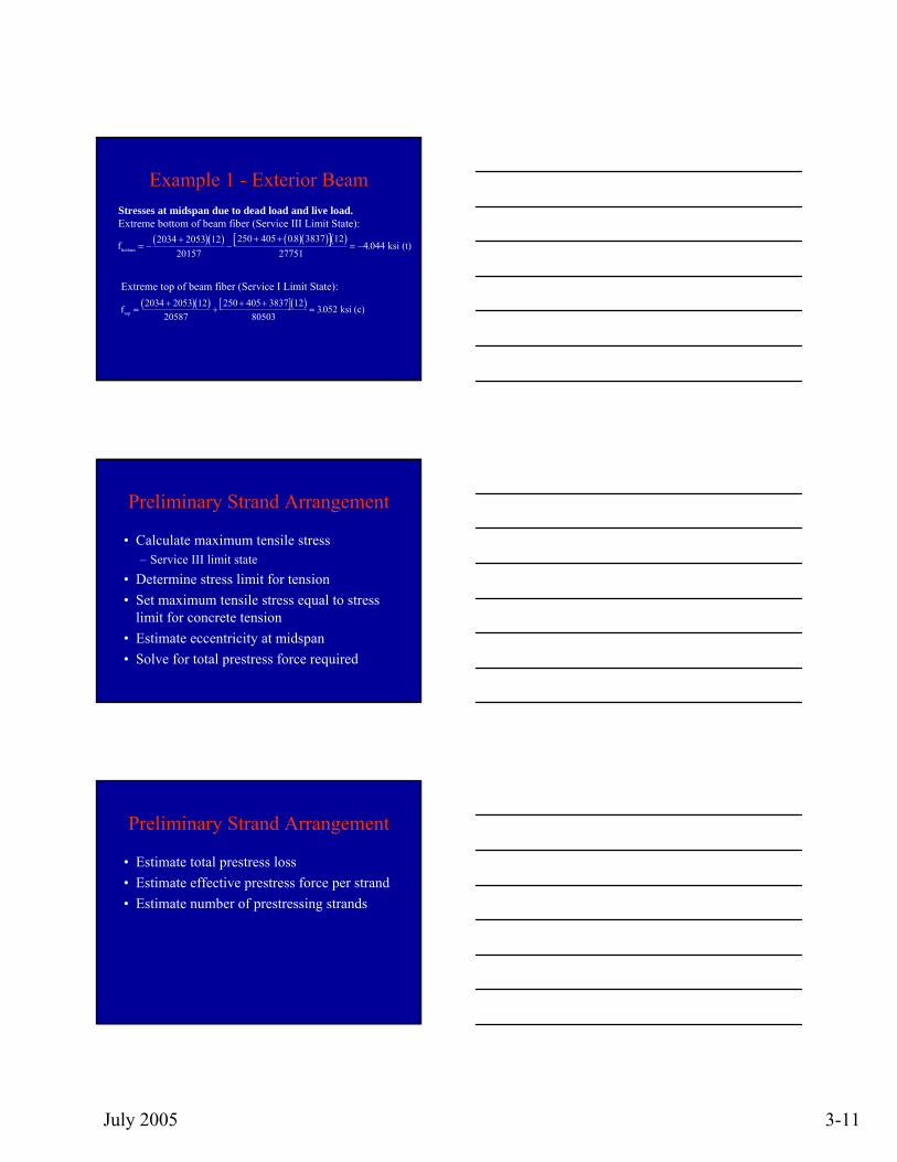
Example 1 - Exterior BeamStresses at midspan due to dead load and live load.Extreme bottom of beam fiber (Service III Limit State):
( )( ) ( )( )[ ]( )fbottom = −+
−+ +
= −2034 2053 12
20157250 405 08 3837 12
277514 044
.. ksi (t)
Extreme top of beam fiber (Service I Limit State):( )( ) [ ]( )ftop =
++
+ +=
2034 2053 1220587
250 405 3837 1280503
3052. ksi (c)
Preliminary Strand Arrangement
• Calculate maximum tensile stress– Service III limit state
• Determine stress limit for tension• Set maximum tensile stress equal to stress
limit for concrete tension• Estimate eccentricity at midspan• Solve for total prestress force required
Preliminary Strand Arrangement
• Estimate total prestress loss• Estimate effective prestress force per strand• Estimate number of prestressing strands
July 2005 3-12
Preliminary Strand Arrangement
fPA
PeS
ftenb
bottom= − +
f fPA
PeS
PA
eSten bottom
b b− = − = −
⎛⎝⎜
⎞⎠⎟
1
Pf f
Ae
S
ten bottom
b
=−
−⎛⎝⎜
⎞⎠⎟
1
Preliminary Strand Arrangement
fpe = fpj – estimated lossesPe = (fpe)(Aps)
NoPPe
. Strands =
Example
• Preliminary strand arrangement
July 2005 3-13
Preliminary Strand Arrangement
Example 1
Example 1BEAM STRESSESBottom fiber, maximum tension stress, all loads applied, Service III Limit State:
Interior beam, fbottom = -3.710 ksiExterior beam, fbottom = -4.044 ksi
CONCRETE STRESS LIMITLimit for tension, all loads applied, after all losses:
f ften c= = =0 0948 0 0948 8 0 268. . .' ksi
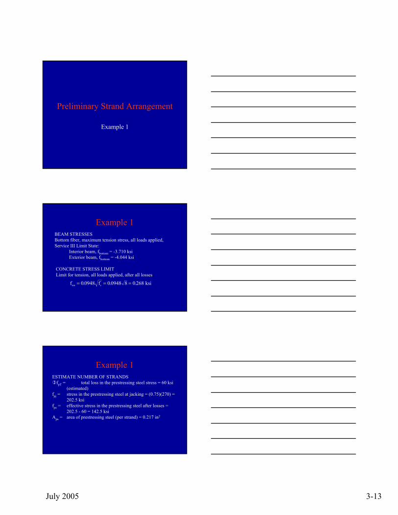
Example 1ESTIMATE NUMBER OF STRANDS
fpT = total loss in the prestressing steel stress = 60 ksi (estimated)
fpj = stress in the prestressing steel at jacking = (0.75)(270) = 202.5 ksi
fpe = effective stress in the prestressing steel after losses = 202.5 - 60 = 142.5 ksi
Aps = area of prestressing steel (per strand) = 0.217 in2
July 2005 3-14
Example 1ESTIMATE NUMBER OF STRANDSPe = effective prestressing force in one strand = (fpe)(Aps) =
(142.5)(0.217) = 30.9 kA= area of non-composite beam = 1085 in2
Sb = section modulus, non-composite section, extreme bottom beam fiber = 20157 in3
e = eccentricity of prestress force at midspan = -32 in (estimated)
Example 1 - Exterior Beam(114)(0.7906) = 90.12"
C. G. Beam
C. G. Composite Section
53.5
4"
36.3
8"
C. G. Slab
72"
9"
76.5
0"
17.1
6"
22.9
6"
Example 1 - Interior BeamEstimated total prestress force required:
( ) ( )( )P f f
Ae
S
ten bottom
b
=−
−⎛⎝⎜
⎞⎠⎟
=− − −
−−⎡
⎣⎢⎤⎦⎥
=1
0 268 2 7101
108532
20157
13718. .
. k
Estimated number of strands required:
No PPe
. ..
. Strands = = =1371830 9
44 4
July 2005 3-15
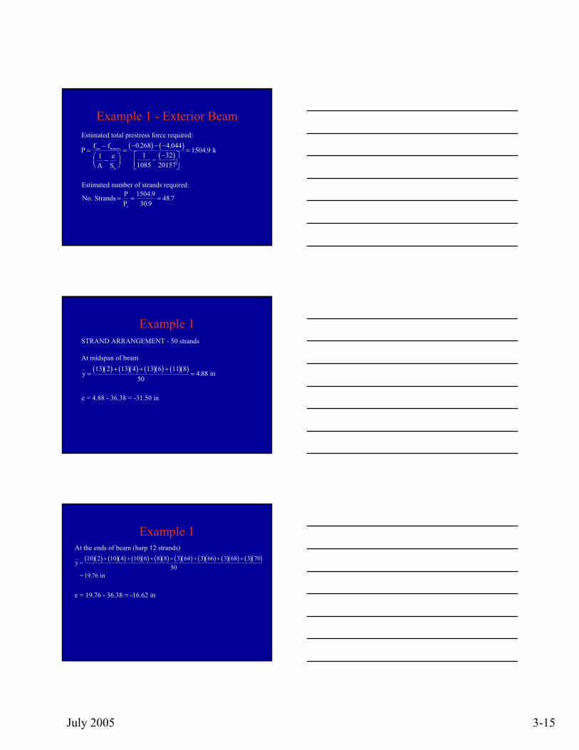
Example 1 - Exterior BeamEstimated total prestress force required:
( ) ( )( )P f f
Ae
S
ten bottom
b
=−
−⎛⎝⎜
⎞⎠⎟
=− − −
−−⎡
⎣⎢⎤⎦⎥
=1
0 268 4 0441
108532
20157
1504 9. .
. k
Estimated number of strands required:
No PPe
. ..
. Strands = = =1504 9
30 948 7
Example 1STRAND ARRANGEMENT - 50 strands
At midspan of beam
( )( ) ( )( ) ( )( ) ( )( )y =+ + +
=13 2 13 4 13 6 11 8
504 88. in
e = 4.88 - 36.38 = -31.50 in
Example 1At the ends of beam (harp 12 strands)
( )( ) ( )( ) ( )( ) ( )( ) ( )( ) ( )( ) ( )( ) ( )( )y =+ + + + + + +10 2 10 4 10 6 8 8 3 64 3 66 3 68 3 70
5019 76 = in.
e = 19.76 - 36.38 = -16.62 in
July 2005 3-16
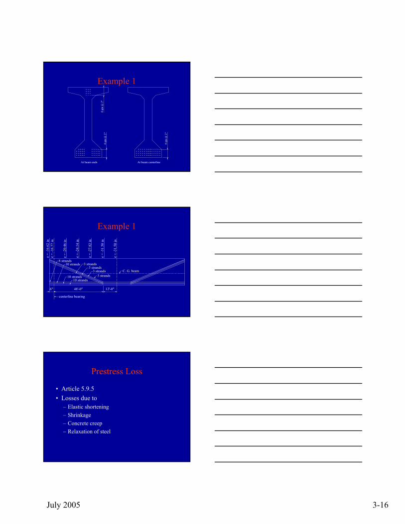
Example 1
At beam ends
4 sp
a @
2"
At beam centerline4
spa
@ 2
"
4 sp
a @
2"
Example 1
C. G. beam
12'-0"
10 strands 3 strands
3 strands3 strands
8 strands10 strands
10 strands
3 strands
48'-0"6"
e =
-16.
6 2 in
e =
-16 .
7 7 i n
e =
-20.
46 in
e =
-24.
1 4 in
e =
-27 .
8 2 i n
e =
- 31 .
50 in
e =
-31.
5 0 in
centerline bearing
Prestress Loss
• Article 5.9.5• Losses due to
– Elastic shortening– Shrinkage– Concrete creep– Relaxation of steel
July 2005 3-17
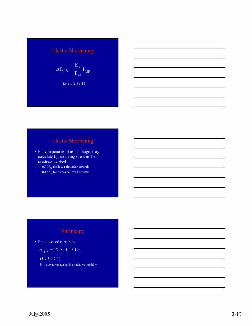
Elastic Shortening
∆fEE
fpESp
cicgp=
(5.9.5.2.3a-1)
Elastic Shortening
• For components of usual design, may calculate fcgp assuming stress in the prestressing steel – 0.70fpu for low relaxation strands– 0.65fpu for stress relieved strands
Shrinkage
• Pretensioned members
∆fpSR = −17 0 0150. . H
(5.9.5.4.2-1) H = average annual ambient relative humidity
July 2005 3-18
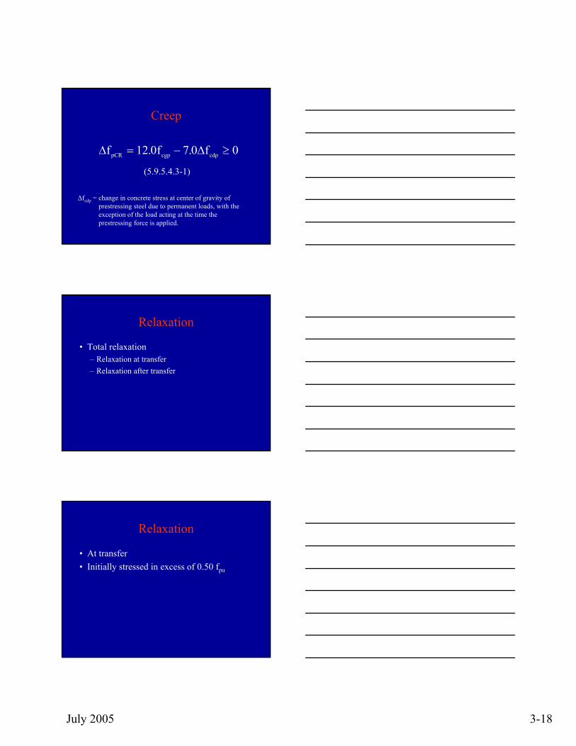
Creep
(5.9.5.4.3-1)
∆ ∆f f fpCR cgp cdp= − ≥12 0 7 0 0. .
∆fcdp = change in concrete stress at center of gravity ofprestressing steel due to permanent loads, with the exception of the load acting at the time theprestressing force is applied.
Relaxation
• Total relaxation– Relaxation at transfer– Relaxation after transfer
Relaxation
• At transfer• Initially stressed in excess of 0.50 fpu
July 2005 3-19
Relaxation
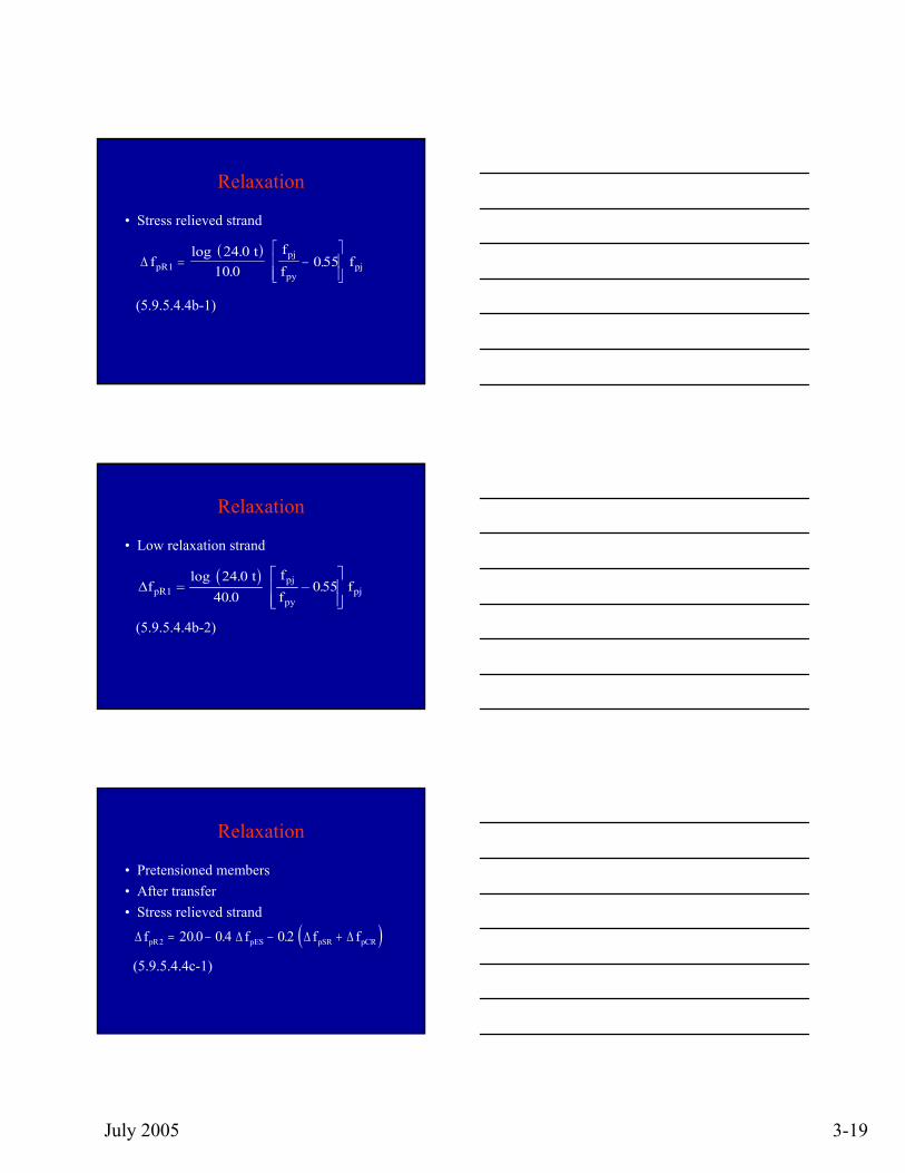
• Stress relieved strand
(5.9.5.4.4b-1)
( )∆ f
ffpR
pj
pypj1
24 010 0
055= −⎡
⎣⎢⎢
⎤
⎦⎥⎥
log ..
. t
f
Relaxation
• Low relaxation strand
( )∆f
ffpR
pj
pypj1
24 040 0
055= −⎡
⎣⎢⎢
⎤
⎦⎥⎥
log ..
. t
f
(5.9.5.4.4b-2)
Relaxation
• Pretensioned members• After transfer• Stress relieved strand
( )∆ ∆ ∆ ∆f f f fpR pES pSR pCR2 20 0 0 4 0 2= − − +. . .
(5.9.5.4.4c-1)
July 2005 3-20
Relaxation
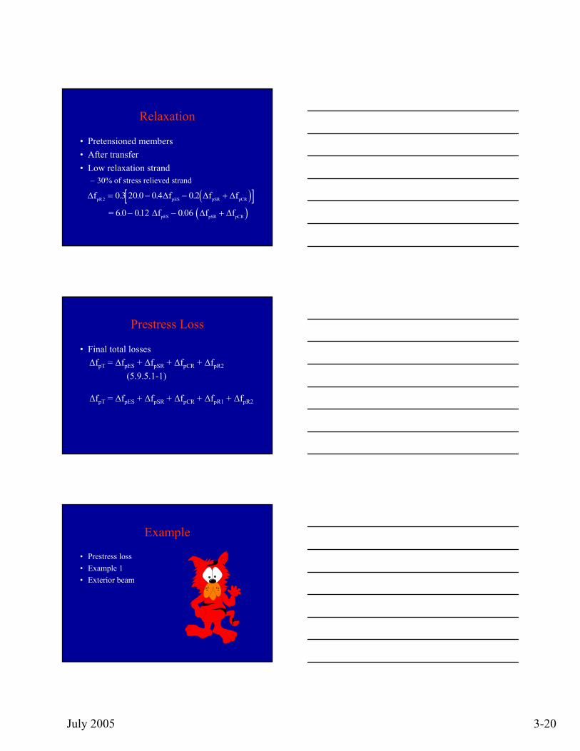
• Pretensioned members• After transfer• Low relaxation strand
– 30% of stress relieved strand
( )[ ]( )
∆ ∆ ∆ ∆
∆ ∆ ∆
f f f f
f f fpR pES pSR pCR
pES pSR pCR
2 0 3 20 0 0 4 0
6 0 012 0 06
= − − +
− − +
. . . .
. . .
2
=
Prestress Loss
• Final total losses∆fpT = ∆fpES + ∆fpSR + ∆fpCR + ∆fpR2
(5.9.5.1-1)
∆fpT = ∆fpES + ∆fpSR + ∆fpCR + ∆fpR1 + ∆fpR2
Example
• Prestress loss• Example 1• Exterior beam
July 2005 3-21
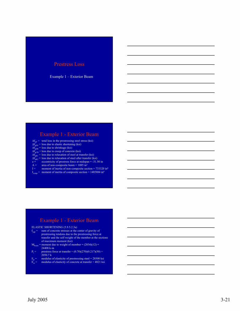
Prestress Loss
Example 1 – Exterior Beam
Example 1 - Exterior Beam∆fpT = total loss in the prestressing steel stress (ksi)∆fpES = loss due to elastic shortening (ksi)∆fpSR = loss due to shrinkage (ksi)∆fpCR = loss due to creep of concrete (ksi)∆fpR1 = loss due to relaxation of steel at transfer (ksi)∆fpR2 = loss due to relaxation of steel after transfer (ksi)e = eccentricity of prestress force at midspan = -31.50 inA = area of non-composite beam = 1085 in2
I = moment of inertia of non-composite section = 733320 in4
Icomp = moment of inertia of composite section = 1485884 in4
Example 1 - Exterior BeamELASTIC SHORTENING (5.9.5.2.3a)fcgp = sum of concrete stresses at the center of gravity of
prestressing tendons due to the prestressing force at transfer and the self weight of the member at the sections of maximum moment (ksi)
Mbeam = moment due to weight of member = (2034)(12) = 24408 k-in
Pt = prestress force at transfer = (0.70)(270)(0.217)(50) = 2050.7 k
Ep = modulus of elasticity of prestressing steel = 28500 ksi Eci = modulus of elasticity of concrete at transfer = 4821 ksi
July 2005 3-22
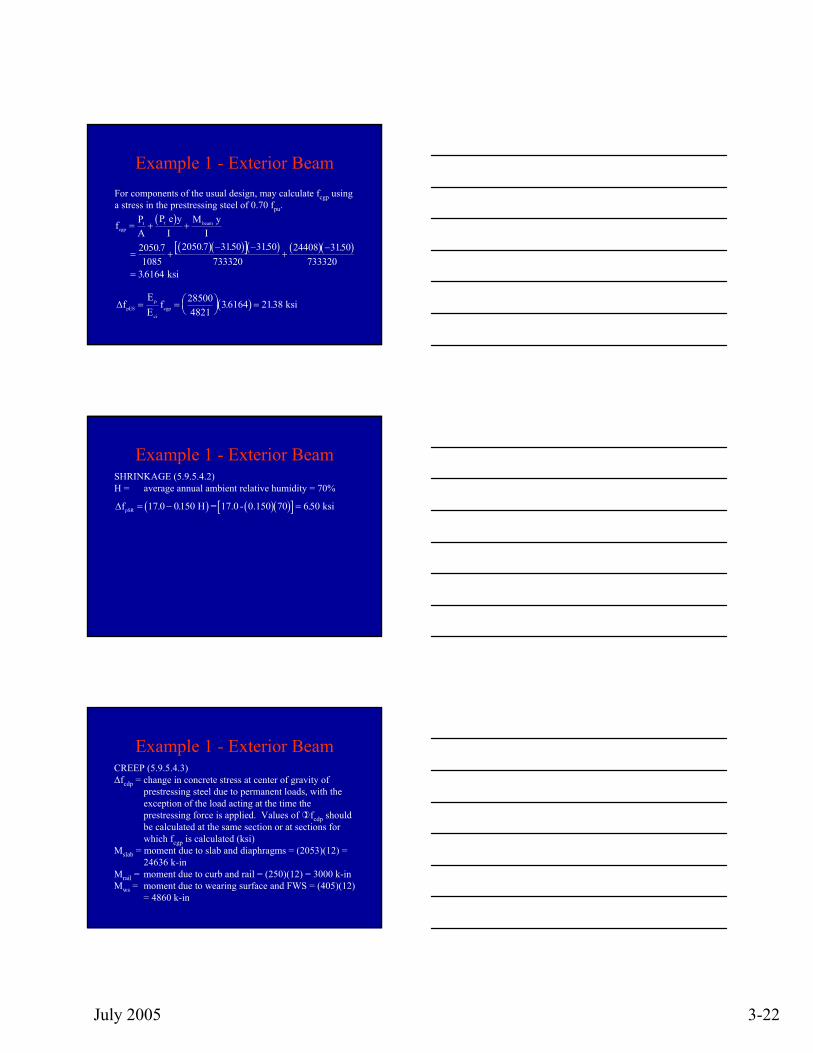
Example 1 - Exterior BeamFor components of the usual design, may calculate fcgp using a stress in the prestressing steel of 0.70 fpu.
( )
( )( )[ ]( ) ( )( )
f PA
P y Mcgp
t t beam= + +
= +− −
+−
=
eI
yI
ksi
2050 71085
2050 7 3150 3150733320
24408 3150733320
36164
. . . . .
.
( )∆fEE
fpESp
cicgp= = ⎛
⎝⎜⎞⎠⎟
=285004821
36164 2138. . ksi
Example 1 - Exterior BeamSHRINKAGE (5.9.5.4.2)H = average annual ambient relative humidity = 70%
( ) ( )( )[ ]∆fpSR = − =17 0 0150 70 650. . . H = 17.0 - 0.150 ksi
Example 1 - Exterior BeamCREEP (5.9.5.4.3)∆fcdp = change in concrete stress at center of gravity of
prestressing steel due to permanent loads, with the exception of the load acting at the time the prestressing force is applied. Values of fcdp should be calculated at the same section or at sections for which fcgp is calculated (ksi)
Mslab = moment due to slab and diaphragms = (2053)(12) = 24636 k-in
Mrail = moment due to curb and rail = (250)(12) = 3000 k-inMws = moment due to wearing surface and FWS = (405)(12)
= 4860 k-in
July 2005 3-23
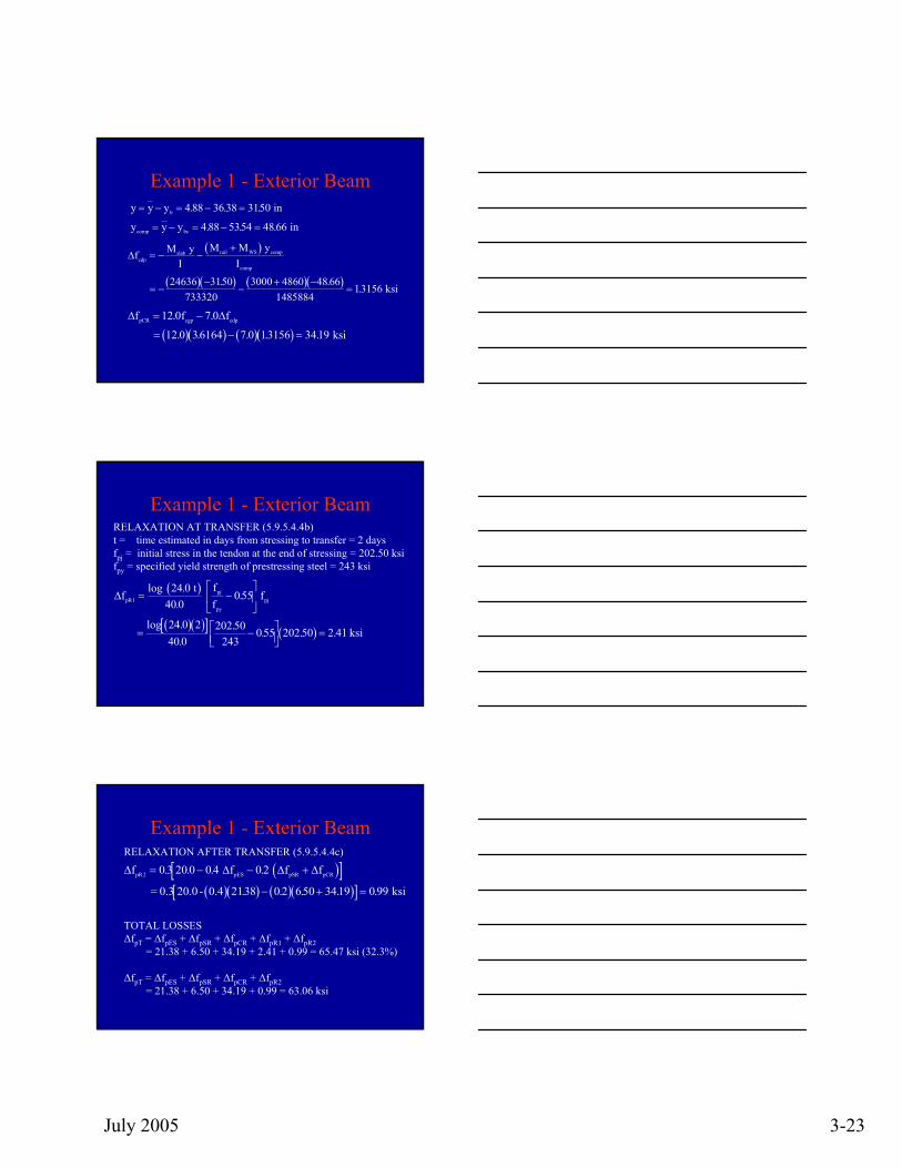
Example 1 - Exterior Beam
( )
( )( ) ( )( )
∆f MI
M MIcdp
slab rail WS
comp
= − −+
= −−
−+ −
=
y y
ksi
comp
24636 3150733320
3000 4860 48 661485884
13156. .
.
( )( ) ( )( )∆ ∆f f fpCR cgp cdp= −
= − =
12 0 7 0
12 0 36164 7 0 13156 3419
. .
. . . . . ksi
y y yb= − = − =4 88 36 38 3150. . . in
y y ycomp bc= − = − =4 88 5354 48 66. . . in
Example 1 - Exterior BeamRELAXATION AT TRANSFER (5.9.5.4.4b)t = time estimated in days from stressing to transfer = 2 daysfpj = initial stress in the tendon at the end of stressing = 202.50 ksifpy = specified yield strength of prestressing steel = 243 ksi
( )
( )( )[ ] ( )
∆fffpR
pj
pypj1
24 040 0
055
24 0 240 0
202 50243
055 202 50 2 41
= −⎡
⎣⎢
⎤
⎦⎥
= −⎡⎣⎢
⎤⎦⎥
=
log ..
.
log ..
. . . .
t f
ksi
Example 1 - Exterior BeamRELAXATION AFTER TRANSFER (5.9.5.4.4c)
( )[ ]( )( ) ( )( )[ ]
∆ ∆ ∆ ∆f f f fpR pES pSR pCR2 0 3 20 0 0 4 0 2
2138 0 2 650 3419 0 99
= − − +
− + =
. . . .
. . . . .
= 0.3 20.0 - 0.4 ksi
TOTAL LOSSES∆fpT = ∆fpES + ∆fpSR + ∆fpCR + ∆fpR1 + ∆fpR2
= 21.38 + 6.50 + 34.19 + 2.41 + 0.99 = 65.47 ksi (32.3%)
∆fpT = ∆fpES + ∆fpSR + ∆fpCR + ∆fpR2= 21.38 + 6.50 + 34.19 + 0.99 = 63.06 ksi
July 2005 3-24
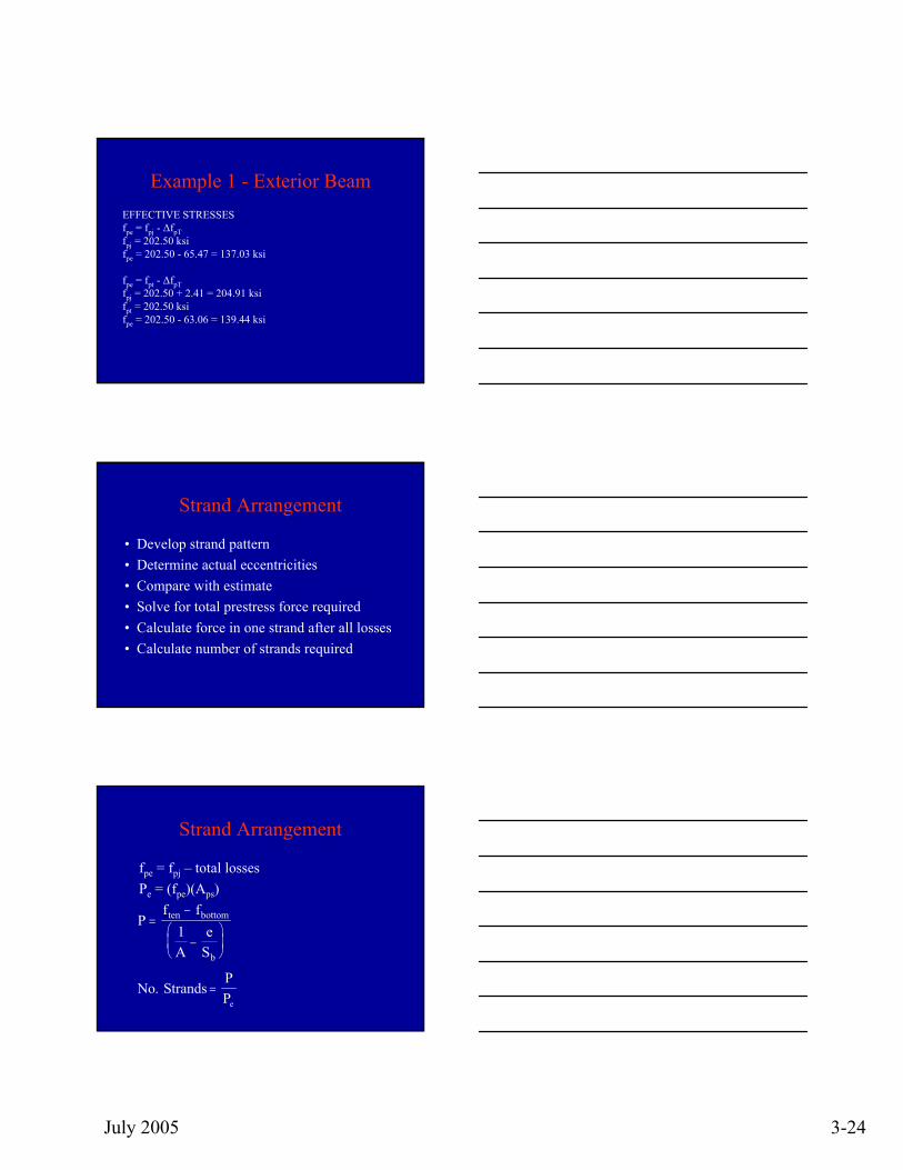
Example 1 - Exterior BeamEFFECTIVE STRESSES fpe = fpj - ∆fpTfpj = 202.50 ksifpe = 202.50 - 65.47 = 137.03 ksi
fpe = fpt - ∆fpTfpj = 202.50 + 2.41 = 204.91 ksifpt = 202.50 ksifpe = 202.50 - 63.06 = 139.44 ksi
Strand Arrangement
• Develop strand pattern• Determine actual eccentricities• Compare with estimate• Solve for total prestress force required• Calculate force in one strand after all losses• Calculate number of strands required
Strand Arrangement
fpe = fpj – total lossesPe = (fpe)(Aps)
Pf f
Ae
S
ten bottom
b
=−
−⎛⎝⎜
⎞⎠⎟
1
NoPPe
. Strands =

July 2005 3-25
Example
• Strand arrangement
Strand Arrangement
Example 1
Example 1fbottom = extreme bottom beam fiber tensile stress from
applied loads interior beam = -3.710 ksiexterior beam = -4.044 ksi
ften = allowable tensile stress in concrete after losses = 0.268 ksi
fpj = stress in prestressing steel at jacking = (0.75)(270) = 202.50 ksi
fpe = effective stress in prestressing steel after losses interior beam = 202.50 – 61.54 = 140.96 ksiexterior beam = 202.50 – 61.82 = 140.68 ksi
July 2005 3-26
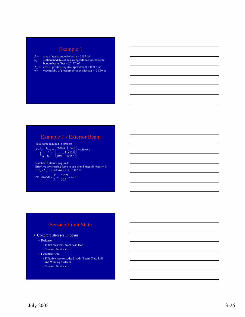
Example 1A = area of non-composite beam = 1085 in2
Sb = section modulus of non-composite section, extreme bottom beam fiber = 20157 in3
Aps = area of prestressing steel (per strand) = 0.217 in2
e = eccentricity of prestress force at midspan = -31.50 in
Example 1 - Exterior Beam
Number of strands required:Effective prestressing force in one strand after all losses = Pe= (fpe)(Aps) = (140.96)(0.217) = 30.5 k
No PPe
. ..
. strands = = =1519 9
30549 8
Total force required in strands:( ) ( )
( )P f f
Ae
S
ten bottom
b
=−
−⎛⎝⎜
⎞⎠⎟
=− − −
−−⎡
⎣⎢⎤⎦⎥
=1
0 268 4 0441
10852146
20157
1519 9. ..
. k
Service Limit State
• Concrete stresses in beam– Release
• Initial prestress, beam dead load• Service I limit state
– Construction• Effective prestress, dead loads (Beam, Slab, Rail
and Wearing Surface)• Service I limit state
July 2005 3-27
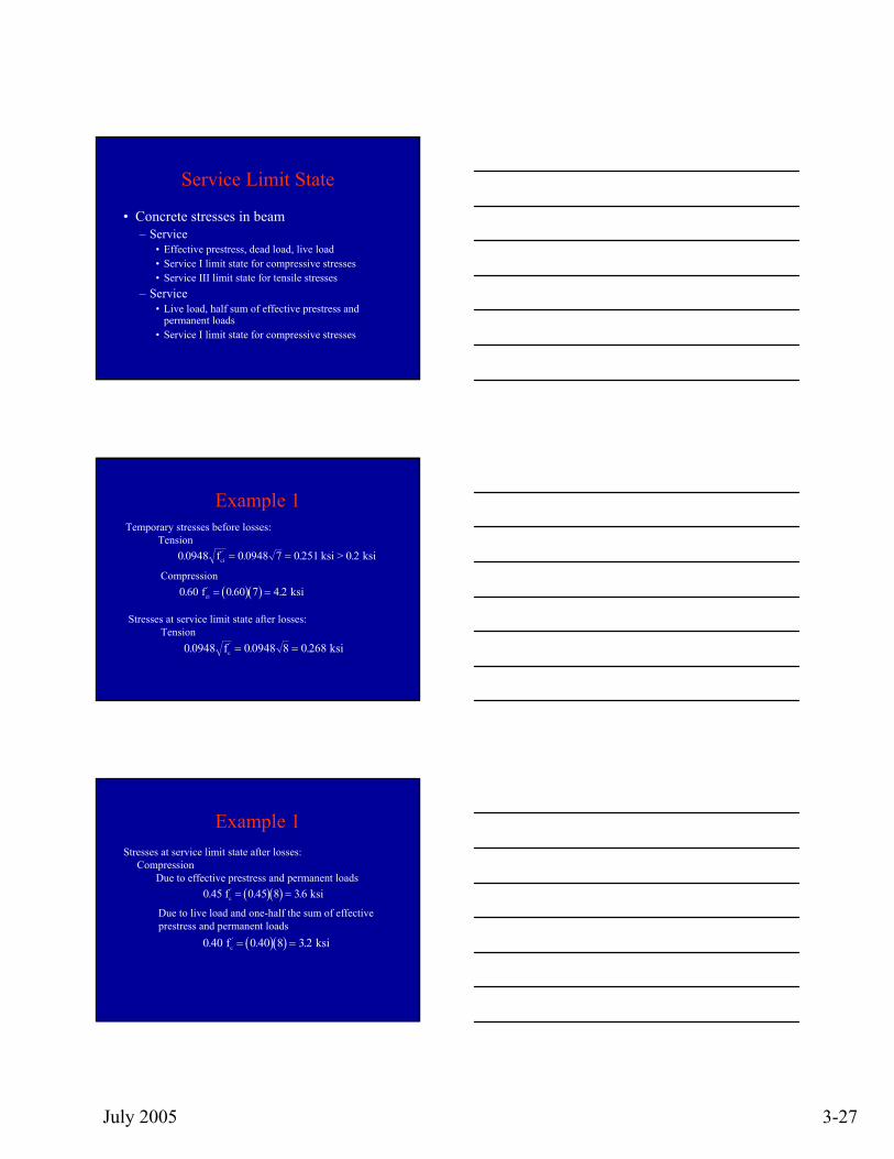
Service Limit State
• Concrete stresses in beam– Service
• Effective prestress, dead load, live load• Service I limit state for compressive stresses• Service III limit state for tensile stresses
– Service• Live load, half sum of effective prestress and
permanent loads• Service I limit state for compressive stresses
Example 1Temporary stresses before losses:
Tension0 0948 0 0948 7 0 251 0 2. . . .'fci = = ksi > ksi
Compression( )( )0 60 0 60 7 4 2. . .' f ksici = =
Stresses at service limit state after losses:Tension
0 0948 0 0948 8 0 268. . .'fc = = ksi
Example 1Stresses at service limit state after losses:
CompressionDue to effective prestress and permanent loads
( )( )0 45 0 45 8 36. . .' f ksic = =
Due to live load and one-half the sum of effective prestress and permanent loads
( )( )0 40 0 40 8 32. . .' f ksic = =
July 2005 3-28
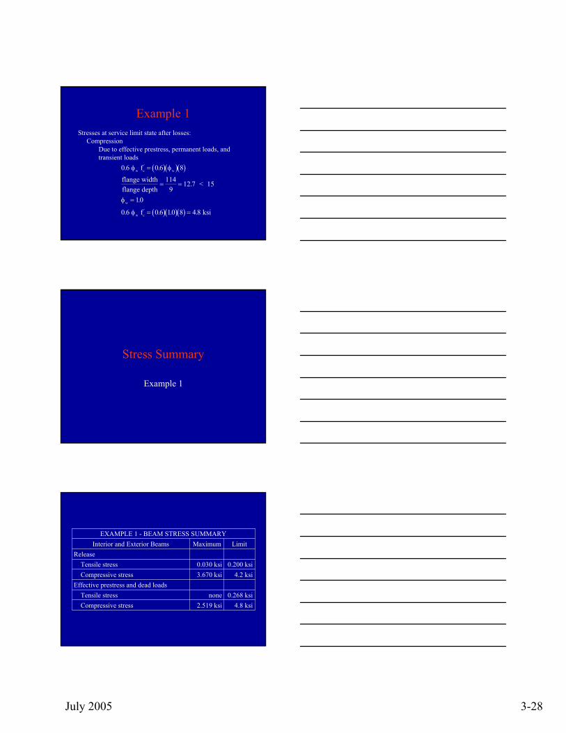
Example 1Stresses at service limit state after losses:
CompressionDue to effective prestress, permanent loads, and transient loads
( )( )( )0 6 0 6 10 8 4 8. . . . f ksic'φw = =
flange wid
w
thflange depth
< 15= =
=
1149
12 7
10
.
.φ
( )( )( )0 6 0 6 8. . fc'φ φw w=
Stress Summary
Example 1
4.8 ksi2.519 ksiCompressive stress0.268 ksinone Tensile stress
Effective prestress and dead loads4.2 ksi3.670 ksiCompressive stress
0.200 ksi0.030 ksiTensile stressRelease
LimitMaximumInterior and Exterior BeamsEXAMPLE 1 - BEAM STRESS SUMMARY
July 2005 3-29
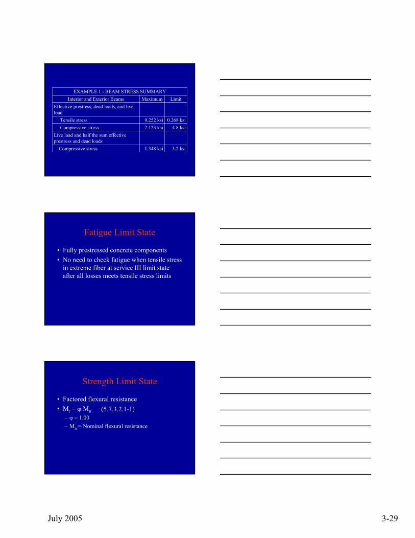
4.8 ksi2.123 ksiCompressive stress
3.2 ksi1.348 ksiCompressive stress
Live load and half the sum effective prestress and dead loads
0.268 ksi0.252 ksiTensile stress
Effective prestress, dead loads, and live load
LimitMaximumInterior and Exterior BeamsEXAMPLE 1 - BEAM STRESS SUMMARY
Fatigue Limit State
• Fully prestressed concrete components• No need to check fatigue when tensile stress
in extreme fiber at service III limit state after all losses meets tensile stress limits
Strength Limit State
• Factored flexural resistance• Mr = φ Mn
– φ = 1.00– Mn = Nominal flexural resistance
(5.7.3.2.1-1)
July 2005 3-30
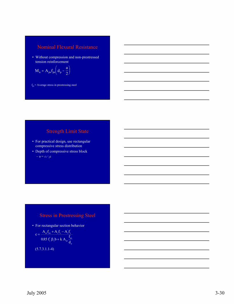
Nominal Flexural Resistance
• Without compression and non-prestressed tension reinforcement
M A f da
n ps ps p= −⎛⎝⎜
⎞⎠⎟2
fps = Average stress in prestressing steel
Strength Limit State
• For practical design, use rectangular compressive stress distribution
• Depth of compressive stress block – a = 1c
Stress in Prestressing Steel
• For rectangular section behavior
cA f A f A f
b k Afd
ps pu s y s y
c pspu
p
=+ −
+
' '
'.085 1 f β
(5.7.3.1.1-4)
July 2005 3-31
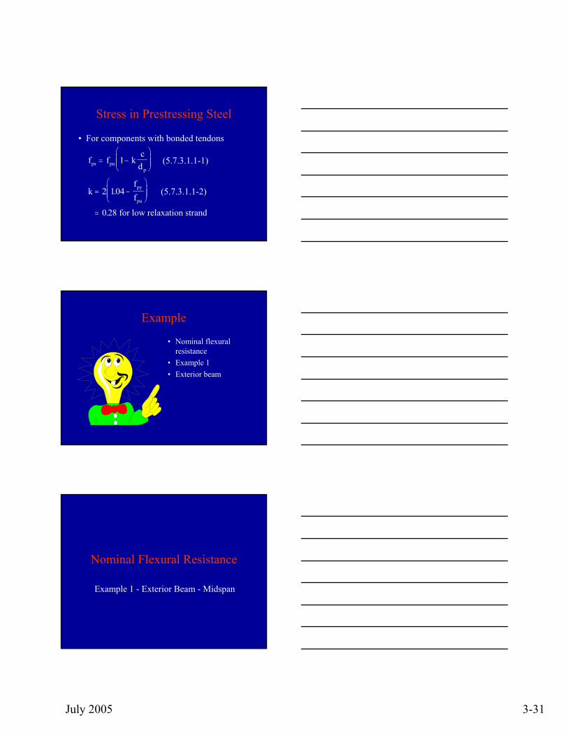
Stress in Prestressing Steel
• For components with bonded tendons
f f kc
d
kff
ps pup
py
pu
= −⎛
⎝⎜⎜
⎞
⎠⎟⎟
= −⎛
⎝⎜⎜
⎞
⎠⎟⎟
=
1
2 104
0 28
.
. for low relaxation strand
(5.7.3.1.1-1)
(5.7.3.1.1-2)
Example
• Nominal flexural resistance
• Example 1• Exterior beam
Nominal Flexural Resistance
Example 1 - Exterior Beam - Midspan
July 2005 3-32
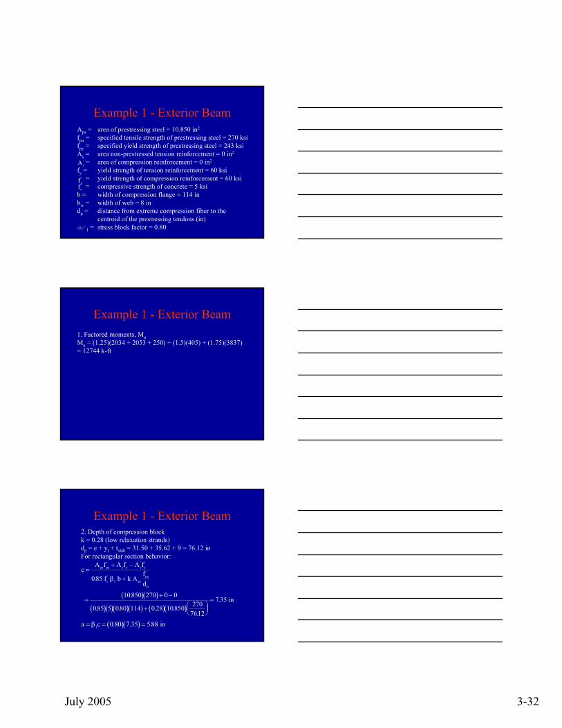
Example 1 - Exterior BeamAps = area of prestressing steel = 10.850 in2
fpu = specified tensile strength of prestressing steel = 270 ksifpy = specified yield strength of prestressing steel = 243 ksiAs = area non-prestressed tension reinforcement = 0 in2
= area of compression reinforcement = 0 in2
fy = yield strength of tension reinforcement = 60 ksi= yield strength of compression reinforcement = 60 ksi= compressive strength of concrete = 5 ksi
b = width of compression flange = 114 inbw = width of web = 8 indp = distance from extreme compression fiber to the
centroid of the prestressing tendons (in)1 = stress block factor = 0.80
As'
fy'
fc'
Example 1 - Exterior Beam1. Factored moments, MuMu = (1.25)(2034 + 2053 + 250) + (1.5)(405) + (1.75)(3837) = 12744 k-ft
Example 1 - Exterior Beam2. Depth of compression blockk = 0.28 (low relaxation strands)dp = e + yt + tslab = 31.50 + 35.62 + 9 = 76.12 inFor rectangular section behavior:
( )( )( )( )( )( ) ( )( )
cA f A f A f
k Afd
ps pu s y s y
c pspu
p
=+ −
+
=+ −
+ ⎛⎝⎜
⎞⎠⎟=
' '
'.
.
. . . ..
.
085
10850 270 0 0
085 5 080 114 0 28 10850 2707612
7 35
1 f b
in
β
( )( )a c= = =β1 0 80 7 35 588. . . in
July 2005 3-33
Example 1 - Exterior Beam
3. Stress in prestressing steel at nominal flexural resistance, components with bonded tendons
( ) ( )f f k cdps pu
p
= −⎛
⎝⎜
⎞
⎠⎟ = − ⎛
⎝⎜⎞⎠⎟
⎡⎣⎢
⎤⎦⎥=1 270 1 0 28 7 35
7612262 70. .
.. ksi
Example 1 - Exterior Beam
4. Factored flexural resistance
( )( )
M A f d an ps ps p= −⎛
⎝⎜⎞⎠⎟
= − ⎛⎝⎜
⎞⎠⎟
⎡⎣⎢
⎤⎦⎥⎛⎝⎜
⎞⎠⎟=
2
10850 262 70 7612 5882
112
17382 k - ft. . . .
Mr = (1.0)(17382) = 17382 k-ft > 12744 k-ft o.k.
Reinforcement Limits
• Amount of prestressed and non-prestressed reinforcement– Maximum– Minimum
July 2005 3-34
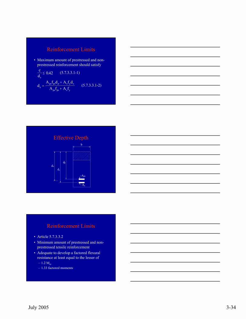
Reinforcement Limits
• Maximum amount of prestressed and non-prestressed reinforcement should satisfycd
dA f d A f d
A f A f
e
eps ps p s y s
ps ps s y
≤
=+
+
0 42. (5.7.3.3.1-1)
(5.7.3.3.1-2)
Effective Depth
b
As
Aps
ds
de
dp
Reinforcement Limits
• Article 5.7.3.3.2• Minimum amount of prestressed and non-
prestressed tensile reinforcement• Adequate to develop a factored flexural
resistance at least equal to the lesser of– 1.2 Mcr
– 1.33 factored moments
July 2005 3-35
Cracking Moment
( )M S f f MSS
S fcr c r cpe dncc
ncc r= + − −
⎛⎝⎜
⎞⎠⎟ ≤1
5.7.3.3.2-1
Example 1 - Exterior BeamThe minimum amount of prestressed and non-prestressed reinforcementMdnc = total unfactored dead load moment acting on the
monolithic or non-composite section Snc = section modulus for the extreme fiber of the monolithic
or non-composite section where tensile stress is caused by externally applied loads
Sc = section modulus for the extreme fiber of the composite section where tensile stress is caused by externally applied loads
fr = modulus of rupturefcpe = compressive stress in concrete due to effective
prestress forces only
Example
• Reinforcement limits• Example 1• Exterior beam
July 2005 3-36
Reinforcement Limits
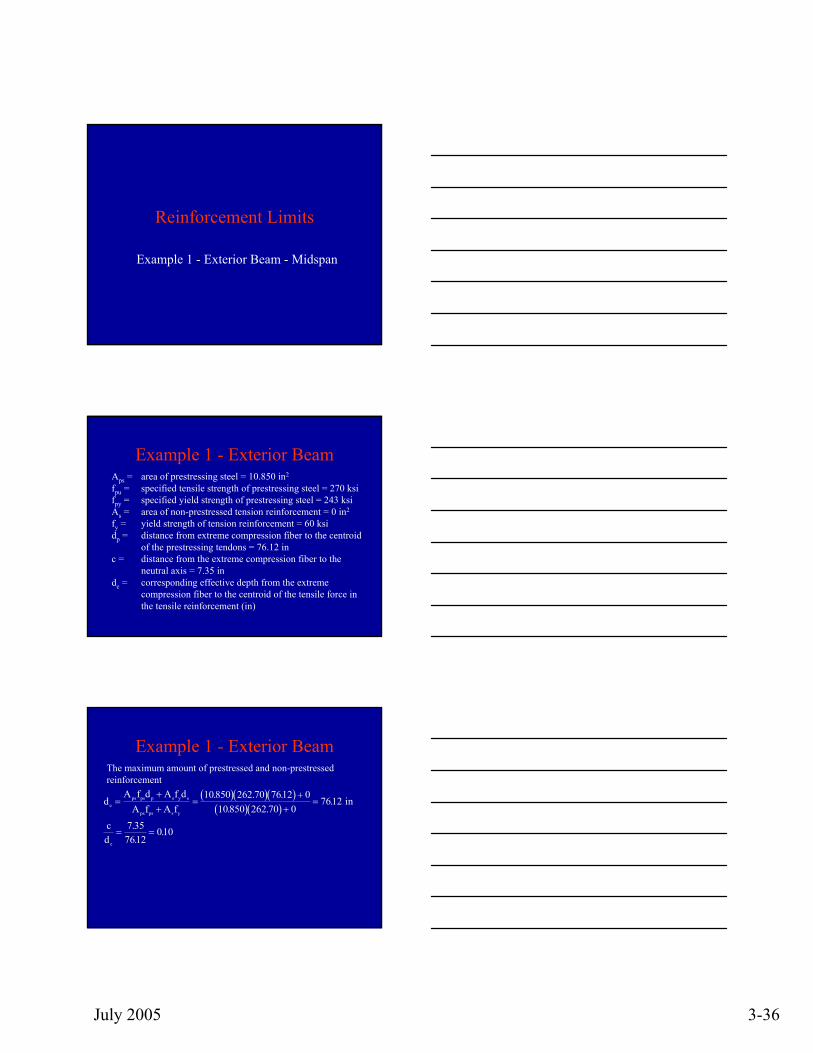
Example 1 - Exterior Beam - Midspan
Example 1 - Exterior BeamAps = area of prestressing steel = 10.850 in2
fpu = specified tensile strength of prestressing steel = 270 ksifpy = specified yield strength of prestressing steel = 243 ksiAs = area of non-prestressed tension reinforcement = 0 in2
fy = yield strength of tension reinforcement = 60 ksidp = distance from extreme compression fiber to the centroid
of the prestressing tendons = 76.12 inc = distance from the extreme compression fiber to the
neutral axis = 7.35 inde = corresponding effective depth from the extreme
compression fiber to the centroid of the tensile force in the tensile reinforcement (in)
Example 1 - Exterior BeamThe maximum amount of prestressed and non-prestressed reinforcement
( )( )( )( )( )
dA f d A f d
A f A fcd
eps ps p s y s
ps ps s y
e
=++
=+
+=
= =
10 850 262 70 7612 010850 262 70 0
7612
7 357612
010
. . .. .
.
..
.
in
July 2005 3-37
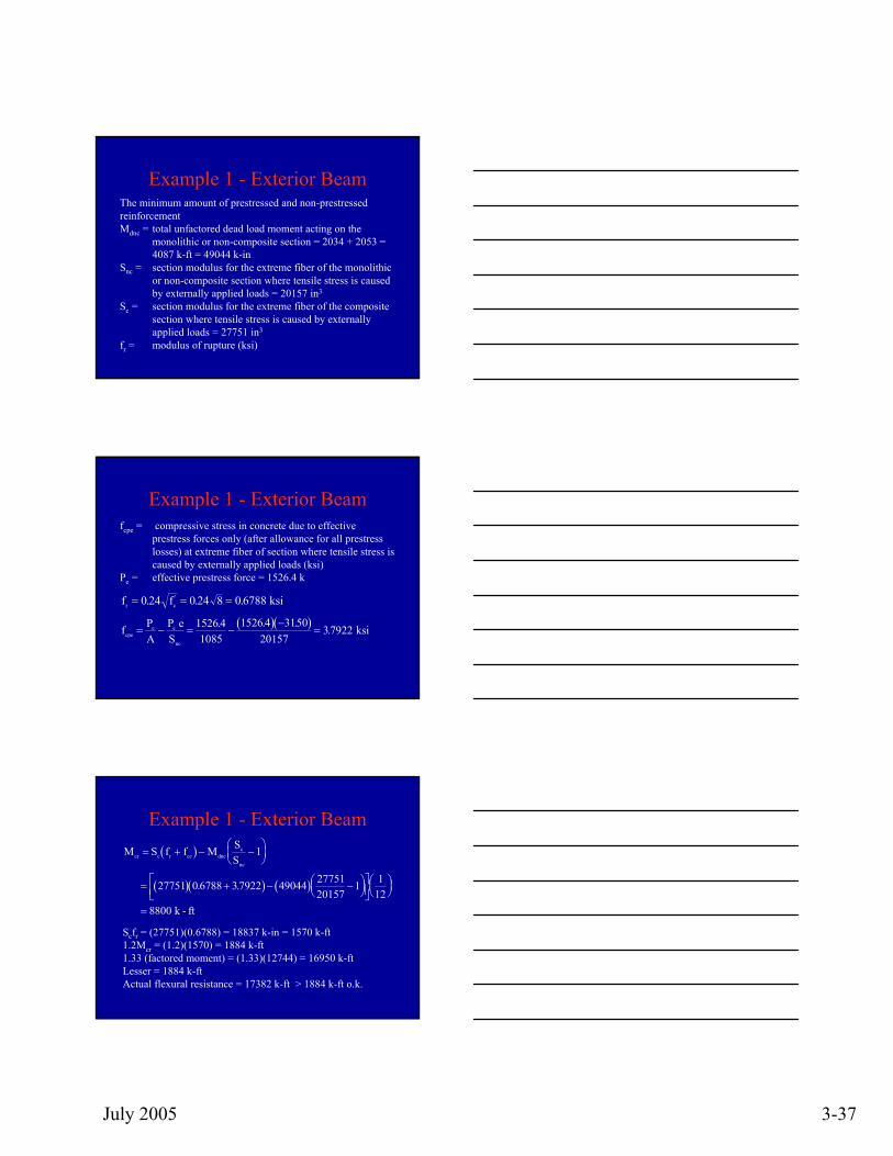
Example 1 - Exterior BeamThe minimum amount of prestressed and non-prestressed reinforcementMdnc = total unfactored dead load moment acting on the
monolithic or non-composite section = 2034 + 2053 = 4087 k-ft = 49044 k-in
Snc = section modulus for the extreme fiber of the monolithic or non-composite section where tensile stress is caused by externally applied loads = 20157 in3
Sc = section modulus for the extreme fiber of the composite section where tensile stress is caused by externally applied loads = 27751 in3
fr = modulus of rupture (ksi)
Example 1 - Exterior Beamfcpe = compressive stress in concrete due to effective
prestress forces only (after allowance for all prestress losses) at extreme fiber of section where tensile stress is caused by externally applied loads (ksi)
Pe = effective prestress force = 1526.4 k
( )( )f PA
PScpe
e e
nc
= − = −−
= e ksi1526 4
10851526 4 3150
2015737922. . ..
f fr c= = =0 24 0 24 8 0 6788. . .' ksi
Example 1 - Exterior Beam( )
( )( ) ( )
M S f f M SScr c r ce dnc
c
nc
= + − −⎛⎝⎜
⎞⎠⎟
= + − −⎛⎝⎜
⎞⎠⎟
⎡⎣⎢
⎤⎦⎥⎛⎝⎜
⎞⎠⎟
=
1
27751 0 6788 37922 49044 2775120157
1 112
8800
k - ft
. .
Scfr = (27751)(0.6788) = 18837 k-in = 1570 k-ft1.2Mcr = (1.2)(1570) = 1884 k-ft1.33 (factored moment) = (1.33)(12744) = 16950 k-ftLesser = 1884 k-ftActual flexural resistance = 17382 k-ft > 1884 k-ft o.k.
July 2005 3-38
Pretensioned Anchorage Zone
• Bursting resistance provided by vertical reinforcement in ends of pretensioned beams at service limit state
• Not less than 4% prestress force at transfer• Total vertical reinforcement located within
a distance h/4 from end of beam
P f Ar s s=
(5.10.10.1-1)
Pretensioned Anchorage Zone
• Confinement reinforcement - 5.10.10.2– In bottom flange– Shaped to enclose strands– Distance 1.5d from beam ends– Minimum bar size
• No. 3 deformed
– Maximum spacing• 6 inches
Example
• Pretensioned anchorage zone
July 2005 3-39
Pretensioned Anchorage Zone
Example 1
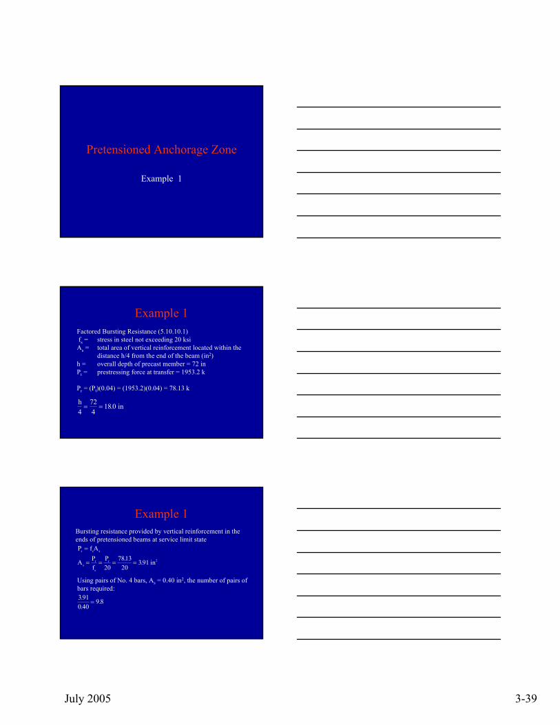
Example 1Factored Bursting Resistance (5.10.10.1)fs = stress in steel not exceeding 20 ksi
As = total area of vertical reinforcement located within the distance h/4 from the end of the beam (in2)
h = overall depth of precast member = 72 inPt = prestressing force at transfer = 1953.2 k
Pr = (Pt)(0.04) = (1953.2)(0.04) = 78.13 k
h4
724
18 0= = . in
Example 1Bursting resistance provided by vertical reinforcement in the ends of pretensioned beams at service limit state:P f Ar s s=
A Pf
Ps
r
s
r= = = =20
781320
391. . in2
Using pairs of No. 4 bars, As = 0.40 in2, the number of pairs of bars required:3 910 40
9 8..
.=
July 2005 3-40
Development Length
• Gradual build up of strand force • Transfer and flexural bond lengths • Determine resistance in the end zone
Development Length
• Prestress force initially varies linearly – Zero at the point where bonding starts – Maximum at the transfer length
Development Length
• Prestress force increases in a parabolic manner between the transfer and development lengths
• Reaches the tensile strength at the development length
July 2005 3-41
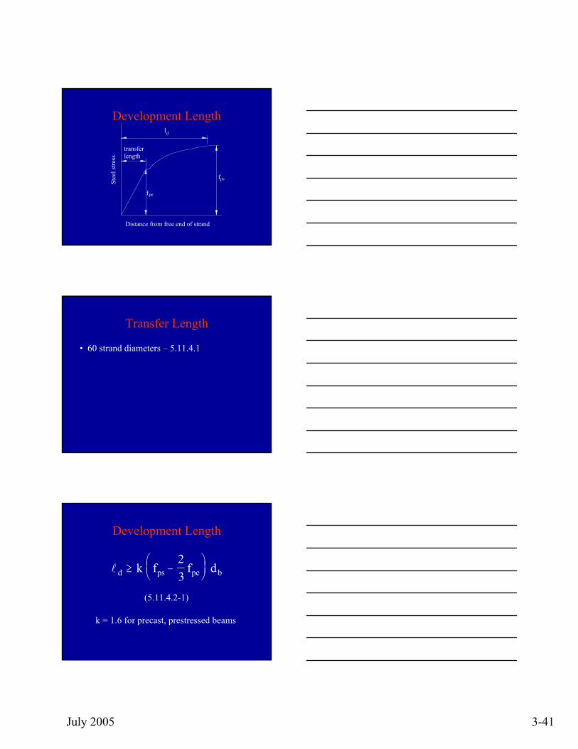
Development Length
f
f
ld
ps
pe
Distance from free end of strand
Stee
l stre
ss
transferlength
Transfer Length
• 60 strand diameters – 5.11.4.1
Development Length
l d ps pe bk f f≥ −⎛⎝⎜
⎞⎠⎟
23
d
(5.11.4.2-1)
k = 1.6 for precast, prestressed beams
July 2005 3-42
Example
• Development length
Development and Transfer Length
Example 1 - Exterior Beam
Example 1 - Exterior BeamTRANSFER LENGTH (5.11.4.1)db = nominal strand diameter = 0.6 in
60 db = (60)(0.6) = 36 in
July 2005 3-43
Example 1 - Exterior BeamBONDED STRAND (5.11.4.2)db = nominal strand diameter = 0.6 infps = average stress in the prestressing steel at the time for
which the nominal resistance of the member is required = 262.70 ksi
fpe = effective stress in the prestressing steel after losses = 140.68 ksi
k = 1.6
( ) ( ) ( )k f fps pe b−⎛⎝⎜
⎞⎠⎟
− ⎛⎝⎜⎞⎠⎟
⎡⎣⎢
⎤⎦⎥
=23
16 262 70 23
140 68 0 6 162 2 d = in. . . . .
Thank You
George Choubah, P.E.FHWA- Federal Lands Highway Bridge Office(703) [email protected]


![Design example flexure 2013-08-20.ppt [Kompatibilitetsläge]](https://img.pdfslide.us/doc/110x75/616a00bd11a7b741a34dbe78/design-example-flexure-2013-08-20ppt-kompatibilitetslge.jpg)