Embed Size (px)
Citation preview

Design of symmetric conic-section flexure hinges basedon closed-form compliance equations
Nicolae Lobontiu a,*, Jeffrey S.N. Paine a, Ephrahim Garcia b,1,Michael Goldfarb b
a Dynamic Structures and Materials, LLC, 205 Williamson Square, Franklin, TN 37064, USAb Center for Intelligent Mechatronics, Vanderbilt University, Nashville, TN 37235, USA
Received 2 January 2001; accepted 28 November 2001
Abstract
The paper develops closed-form compliance equations for conic-section (circular, elliptic, parabolic andhyperbolic) flexure hinges. Finite element simulation results confirm the theoretical formulation data. Themain objectives are to predict the deformation/displacement field of a flexure hinge under loading and toassess the precision of rotation for a specific conic flexure hinge. A non-dimensional analysis is carried outto discuss both problems. Conclusions are formulated regarding the performance of circular, elliptic,parabolic, and hyperbolic flexure hinges. � 2002 Elsevier Science Ltd. All rights reserved.
Keywords: Flexure hinges; Circular; Elliptic; Parabolic; Hyperbolic; Compliance; Rotation precision
1. Introduction
The flexure hinges are increasingly popular with designs requiring one-piece (monolithic)manufacturing, reduced weight, zero backlash, friction and lubrication, motion smoothness, andvirtually infinite resolution.
Applications include accelerometers, gyroscopes, translation micro-positioning stages, motionguides, piezoelectric actuators and motors, high-accuracy alignment devices for optical fibers,missile-control devices, displacement amplifiers, scanning tunneling microscopes, high-precisioncameras, robotic micro-displacement mechanisms, orthotic prostheses, antennas and valves.
*Corresponding author. Tel.: +1-615-595-6665; fax: +1-615-595-6610.
E-mail address: [email protected] (N. Lobontiu).1 Tel.: +1-615-343-6924; fax: 1+615-343-6687.
0094-114X/02/$ - see front matter � 2002 Elsevier Science Ltd. All rights reserved.
PII: S0094-114X(02)00002-2
Mechanism and Machine Theory 37 (2002) 477–498www.elsevier.com/locate/mechmt

Functionally, the ideal flexure hinge permits limited relative rotation of the rigid adjoiningmembers while prohibiting any other types of motion. The typical flexure hinge consists of one ortwo cutouts that are machined in a blank material.
Paros and Weisbord [1], in their fundamental work, presented the design equations, both exactand simplified, for calculating the compliances (spring rates) of single-axis and two-axis circularcutout constant cross-section flexure hinges.
Ragulskis et al. [2] applied the static finite element analysis to one-quarter of circular flexurehinges in order to calculate their compliances. The analysis results were further used to formulate
Nomenclature
A flexure cross-sectional area, intermediate functionC complianceE Young’s modulusF forceI flexure cross-sectional moment of inertia, integralM bending momentN normal forceR radius of a right circular flexure hingeU elastic strain energya flexure length parameterb flexure cross-sectional widthc flexure thickness parameterf functionl lengtht flexure thicknessx; y; z reference axesb; c non-dimensional parametersh rotation angle
Subscriptsa axialb bendingc circulare elastic, elliptich hyperbolici; j; k countersmin, max minimum, maximump parabolicx; y; z reference axes
Superscripts0 right circular flexure hinge
478 N. Lobontiu et al. / Mechanism and Machine Theory 37 (2002) 477–498

an existence criterion based on the deformation of an initially straight cross-section; this allowedspecifying an optimal flexure geometry for minimum bending stiffness.
Smith et al. [3] introduced the elliptic cross-section flexure hinge in an approach similar to thatof Paros and Weisbord [1]. Closed-form equations were derived for the mechanical compliance ofa simple monolithic elliptic cross-section flexure hinge. The elliptical flexure hinge was demon-strated to range in a domain bounded by the circular flexure hinge and the simple beam in termsof its compliance. The model predictions were checked by finite element analysis and experimentalmeasurements. In a recent monograph, Smith [4] presented the basic geometry and analyticmodels of leaf-type springs such as notch or two-axis flexure hinges. Treated was also the problemof incorporating flexures into mechanisms that are designed for precise motion with fast dynamiccontrol.
Lobontiu et al. [5] developed an analytical model of corner-filleted flexure hinges that are in-corporated into planar amplification mechanisms. Compliance factors were formulated that allowevaluating the rotation efficiency, precision of motion and stresses. A corner-filleted flexure hingespans a design space that is limited by the right circular flexure and the simple beam, in terms of itscompliance.
Xu and King [6] performed static finite element analysis of circular, corner-filleted and ellipticflexure hinges. The results revealed that the corner-filleted flexure is the most accurate in terms ofmotion, the elliptic flexure has less stress for the same displacement, while the right circular flexureis the stiffest. Ryu and Gweon [7] modeled the motion errors that are induced by machiningimperfections into a flexure hinge mechanism.
More recently, Lobontiu et al. [8] introduced the parabolic and hyperbolic flexure hinges forplanar mechanisms, by using compliance closed-form solutions to characterize their performancein terms of flexibility, precision of motion and stresses.
The present work attempts to bring together four types of flexure hinges that share a commontrait. By intersecting a cone with a plane in four distinct and non-trivial relative positions, a circle,an ellipse, a parabola or a hyperbola can be produced, respectively (Fig. 1), curves that are usuallytermed conic-sections. The in-pane closed-form compliances are presented for symmetric right
Fig. 1. Conic-sections.
N. Lobontiu et al. / Mechanism and Machine Theory 37 (2002) 477–498 479

circular, right elliptic, parabolic and hyperbolic flexure hinges. A sketch illustrating a genericsymmetric conic-section flexure hinge is shown in Fig. 2 while Fig. 3 indicates the parameters thatdefine one flexure’s geometry. The precision of rotation, quantified by the offset of a flexure’ssymmetry center, is also discussed in terms of compliance. An analysis is performed in terms oftwo non-dimensional parameters that allows comparing the performance of elliptic, parabolic andhyperbolic flexure hinges relative to circular flexure hinges. The analytical model predictions areconfirmed by finite element simulation results within 10% error margins.
2. Basic assumptions
The formulation that follows is based on several assumptions as summarized below:
• The flexure hinges consist of two cutouts that are symmetric with respect to both the longitu-dinal axis and the middle transverse one (Fig. 2).
• Each cutout is a conic section, specifically a circle, ellipse, parabola or hyperbola.• The conic-section flexure hinges are designed to be integrated into amplification mechanisms
that are geometrically and kinematically two-dimensional; this provision reduces the analysis
Fig. 2. Symmetric conic-section flexure hinge.
Fig. 3. Parameters defining half of a symmetric conic-section flexure hinge.
480 N. Lobontiu et al. / Mechanism and Machine Theory 37 (2002) 477–498

to three degrees of freedom (two in-plane translations and a rotation normal to the transla-tions’ plane).
• The flexure hinges are modeled and analyzed as small-displacement Euler–Bernoulli beamssubjected to bending produced by forces and moments; the axial loading is also considered(see Fig. 4) while shearing effects are not taken into account.
• The beam is considered to be fixed at one end and free at the other.
3. Compliance equations
A generic conic-section flexure hinge is defined by the geometric parameters illustrated in Fig. 3.Based on the assumptions previously stated, this flexure can be assimilated to a fixed-free flex-tensional element, as the one sketched in Fig. 4. The displacement–loading relationship at the freeend 1 is of the form:
h1
y1
x1
8<:
9=; ¼
C11 C12 0C12 C22 00 0 C33
24
35 Mz1
Fy1
Fx1
8<:
9=; ð1Þ
and can be formulated by using Castigliano’s second theorem:
h1 ¼oUe
oMz1;
y1 ¼oUe
oFy1
;
x1 ¼oUe
oFx1;
ð2Þ
where the elastic strain energy comprises bending and axial terms:
Ue ¼1
2
Zl
M2
EIdx
�þ
Zl
N 2
EAdx : ð3Þ
Fig. 4. Schematic representation of a flexure hinge with loading.
N. Lobontiu et al. / Mechanism and Machine Theory 37 (2002) 477–498 481

The compliance factors of Eq. (1) are expressed as:
C11 ¼ 12=ðbEÞI1;C12 ¼ �12=ðbEÞI2;C22 ¼ 12=ðbEÞI3;C33 ¼ 1=ðbEÞI4:
ð4Þ
For a variable-thickness cross-section, the integrals of Eq. (4) are expressed in the genericform:
I1 ¼Zl
dx=tðxÞ3;
I2 ¼Zlxdx=tðxÞ3;
I3 ¼Zlx2 dx=tðxÞ3;
I4 ¼Zl
dx=tðxÞ:
ð5Þ
Eqs. (1)–(5) are combined in order to derive the closed-form compliance equations for theconic-section flexure hinges. The formulation that follows is based on two non-dimensional pa-rameters, b and c, that are defined as:
b ¼ t2c
;
c ¼ t2a
:
ð6Þ
3.1. Elliptical flexure hinges
The variable thickness tðxÞ, as shown in Fig. 3, can be expressed as:
tðxÞ2yðxÞ ¼ t þ 2c 1n
� ½1 � ð1 � x=aÞ2�1=2o: ð7Þ
Eq. (7) is used to solve the integrals of Eqs. (5) that are subsequently substituted into Eqs. (4).The compliance equations for an elliptical flexure hinge are:
C11;e ¼6
Ebt2b
ð2 þ bÞ2c
3 þ 4b þ 2b2
1 þ b
"þ 6ð1 þ bÞ
b1=2ð2 þ bÞ1=2ArcTanð1 þ 2=bÞ1=2
#; ð8Þ
C12;e ¼ � t2c
C11;e; ð9Þ
C22;e ¼3
2Eb1
ð1 þ bÞð2 þ bÞ2c3½fe1ðbÞ þ fe2ðbÞ� ð10Þ
482 N. Lobontiu et al. / Mechanism and Machine Theory 37 (2002) 477–498

with;
fe1 ¼ bf3 þ b½6 þ bð11 þ 8b þ 2b2 þ pð1 þ bÞð2 þ b2ÞÞ�g;fe2 ¼ 2b1=2ð2 þ bÞ�1=2ð1 þ bÞ4ð3 � 4b � 2b2ÞArcTanð1 þ 2=bÞ1=2:
ð11Þ
The compliance C33;e is;
C33;e ¼1
Ebbc
2ð1h
þ bÞb�1=2ð2 þ bÞ�1=2ArcTanð1 þ 2=bÞ1=2 � p=2
i: ð12Þ
3.2. Circular flexure hinges
The variable thickness tðxÞ, as shown in Fig. 3, can be expressed as;
tðxÞ2yðxÞ ¼ 2Rþ t � ½xð2R� xÞ�1=2: ð13ÞFor a circular flexure hinge the two non-dimensional parameters b and c are equal since
c ¼ a ¼ R.Eq. (13) is combined with Eqs. (4) and (5) to formulate the compliance equations for a circular
flexure hinge, namely;
C11;c ¼6
Ebt21
ð2 þ bÞ2
3 þ 4b þ 2b2
1 þ b
"þ 6ð1 þ bÞ
b1=2ð2 þ bÞ1=2ArcTanð1 þ 2=bÞ1=2
#; ð14Þ
C12;c ¼ � t2b
C11;c; ð15Þ
C22;c ¼3
2Eb1
ð1 þ bÞð2 þ bÞ2b3½fe1ðbÞ þ fe2ðbÞ�; ð16Þ
C33;c ¼1
Eb2ð1h
þ bÞb�1=2ð2 þ bÞ�1=2ArcTanð1 þ 2=bÞ1=2 � p=2
i: ð17Þ
The fact should be mentioned here that the circle is an ellipse with equal semi-axes ðc ¼ aÞ. Inthis case, since the non-dimensional parameters b and c are equal, the compliance equations for acircular flexure hinge should be retrieved from the corresponding compliance equations for anellipse by taking b ¼ c. This is indeed so, as simply noticed by comparing Eqs. (8) and (14), Eqs.(9) and (15), Eqs. (10) and (16), and Eqs. (12) and (17), respectively.
Another check was performed by comparing the compliance equations derived here for a rightcircular flexure hinge with those provided by Paros and Weisbord [1]. They were identical andthe interested reader can easily verify this by simply taking c ¼ 1 þ b in Eqs. (1), (3), (9) and (25)of [1].
3.3. Parabolic flexure hinges
For a parabolic flexure hinge, the variable thickness tðxÞ, as shown in Fig. 3, can be expressedas;
tðxÞ2yðxÞ ¼ t þ 2cð1 � x=aÞ2: ð18Þ
N. Lobontiu et al. / Mechanism and Machine Theory 37 (2002) 477–498 483

Eq. (18) is now used in conjunction with Eqs. (4) and (5) to formulate the compliance closed-form equations. They are:
C11;p ¼ 3
2Ebt2bð3h
þ 5bÞ þ 3b1=2ð1 þ b2ÞArcCotb1=2ic�1ð1 þ bÞ�2; ð19Þ
C12;p ¼ �t=ð2cÞC11; ð20Þ
C22;p ¼ 3
8Ebbc3
ð3h
þ bÞb�1=2 ArcCotb�1=2iþ ½3 � ð�6 þ bÞb�ð1 þ bÞ�2; ð21Þ
C33;p ¼ 1
Ebb1=2cArcCotb1=2: ð22Þ
3.4. Hyperbolic flexure hinges
The variable thickness tðxÞ, as shown in Fig. 3, of a hyperbolic flexure hinge is;
tðxÞ2yðxÞ ¼ ½t2 þ 4cðcþ tÞð1 � x=aÞ2�1=2: ð23Þ
Eqs. (23), (4) and (5) yield the closed-form compliance expressions for a hyperbola:
C11;h ¼ 12
Ebt2bc�1ð1 þ bÞ�1; ð24Þ
C12;h ¼ �t=ð2cÞC11;h; ð25Þ
C22;h ¼ 3
2Ebbð1 þ bÞ�1ð1 þ 2bÞ�3=2c�3 2ð1
�þ 2bÞ1=2½1 þ bð2 � bÞ�
� b2ð1 þ bÞð1 þ 2bÞ�1=2Log
1 þ b �ffiffiffiffiffiffiffiffiffiffiffiffiffiffi1 þ 2b
p
1 þ b þffiffiffiffiffiffiffiffiffiffiffiffiffiffi1 þ 2b
p� ��
; ð26Þ
C33;h ¼ 1
2Ebbc�1ð1 þ 2bÞ�1=2
Log 1n
þ b�1½1 þ ð1 þ 2bÞ1=2�o: ð27Þ
4. Precision of rotation
The relative rotation of two mechanical members that are connected by a conventional rotationjoint is produced along an axis that passes through the geometric center of the joint, which is fixedprovided one member is also fixed. In the case of a symmetric flexure hinge, the center of rotation(the geometric symmetry center of the flexure) is no longer fixed since the forces and momentsacting on the flexure produce elastic deformations that alter its position.
The displacement of the rotation center of a flexure hinge (point 2 in Fig. 4), can be assessed byapplying two fictitious loads, a horizontal one, Fx2 and a vertical one, Fy2 in addition to the actualload vector made up of Mz1, Fy1 and Fx1. The Castigliano’s second theorem is again utilized to findthe displacements of the rotation center in the form:
484 N. Lobontiu et al. / Mechanism and Machine Theory 37 (2002) 477–498

y2 ¼oUe
oFy2
;
x2 ¼oUe
oFx2:
ð28Þ
The elastic strain energy Ue is given in Eq. (3) and includes now the formal effects of Fx2 and Fy2.The matrix-form equation that relates deformations to the load vector is similar to Eq. (1), namely;
0y2
x2
8<:
9=; ¼
0 0 0C0
12 C022 0
0 0 C033
24
35 Mz1
Fy1
Fx1
8<:
9=;: ð29Þ
The compliances in Eq. (29) define the offset of the rotation center and are calculated similarlyto the ‘full’ compliance factors that were previously derived. The closed-form equations of C0
12, C022
and C033 are given in the following for elliptic, circular, parabolic and hyperbolic flexure hinges.
4.1. Elliptic flexure hinges
The compliance expressions for elliptic flexure hinges are;
C012;e ¼ � 3
2Ebtbc�2ð1 þ bÞ�1; ð30Þ
C022;e ¼
3
4Ebbc�3ð2 þ bÞ�3 f 0
e1ðbÞ�
þ f 0e2ðbÞ
�ð31Þ
with
f 0e1ðbÞ ¼ 12 þ bf2 � 2b½7 þ bð5 þ bÞ� � pð2 þ bÞ3g;f 0
e2ðbÞ ¼ 2ð1 þ bÞ½3ð1 þ 2=bÞ1=2 þ ð1 þ bÞ2ð�3 þ 4b þ 2b2Þ�ArcTanð1 þ 2=bÞ1=2:
ð32Þ
The compliance C033;e is;
C033;e ¼
1
4Ebbc
4ð1h
þ bÞb�1=2ð2 þ bÞ�1=2ArcTanð1 þ 2=bÞ1=2 � p
i: ð33Þ
4.2. Circular flexure hinges
The closed-form compliance equations for circular flexures are:
C012;c ¼ � 3
2Ebtb�1ð1 þ bÞ�1; ð34Þ
C022;c ¼
3
4Ebb�2ð2 þ bÞ�3 f 0
e1ðbÞ�
þ f 0e2ðbÞ
�; ð35Þ
C033;c ¼
1
4Eb4ð1h
þ bÞb�1=2ð2 þ bÞ�1=2ArcTanð1 þ 2=bÞ1=2 � p
i: ð36Þ
It can be seen again that the compliance factors of a circular flexure hinge can be obtained fromthose of an elliptical flexure hinge by taking b ¼ c in Eqs. (30)–(33).
N. Lobontiu et al. / Mechanism and Machine Theory 37 (2002) 477–498 485

4.3. Parabolic flexure hinges
The compliance closed-form equations for parabolic flexure hinges are:
C012;p ¼ � 3
4Ebtð1 þ 2bÞð1 þ bÞ�2k�2; ð37Þ
C022;p ¼ 3
16Ebb 2h
þ b �ffiffiffib
pð1 þ bÞArcCot
ffiffiffib
p ið1 þ bÞ�1c�3; ð38Þ
C033;p ¼ 1
2Eb
ffiffiffib
pc�1 ArcCot
ffiffiffib
p: ð39Þ
4.4. Hyperbolic flexure hinges
For hyperbolic flexure hinges, the compliance closed-form equations are;
C012;h ¼ � 3
Ebtb2ð1 þ 2bÞ�1c�2; ð40Þ
C022;h ¼ 3
2Ebb
ð1 þ 2bÞc�31
�� bð1 þ 2bÞ�3=2
Log b 1��
þ b �ffiffiffiffiffiffiffiffiffiffiffiffiffiffi1 þ 2b
p ��1��
; ð41Þ
C033;h ¼ 1
2Ebbffiffiffiffiffiffiffiffiffiffiffiffiffiffiffiffi
1 þ 2bcp Log b 1
��þ b �
ffiffiffiffiffiffiffiffiffiffiffiffiffiffi1 þ 2b
p ��1�: ð42Þ
5. Finite element verification of the compliance closed-form equations
The closed-form compliance expressions were checked by the finite element method. TheANSYS finite element software was utilized to calculate the compliance factors for several conic-section flexure designs under static loading. The procedure consisted of applying a unit load atpoint 1, Fig. 5, and reading the displacements at the same point, which, in this case, were identicalto the corresponding compliance factors, as shown by Eq. (1). Plane, six degree of freedom pernode elements were used, together with the ‘smart’ meshing capability of the software that au-
Fig. 5. Finite element model.
486 N. Lobontiu et al. / Mechanism and Machine Theory 37 (2002) 477–498

tomatically produced a refined mesh in the flexure areas where stress concentration effects weremost likely to occur. The constant-valued material and geometric data were
• E ¼ 110 � 109 N m�2,• l ¼ 0:33,• b ¼ 0:01 m,• Fy1 ¼ Fx1 ¼ 1 N,• Mz1 ¼ 1 N m.
The finite element and analytic results of the compliance factors are given in Table 1 for severalconic-sections flexure designs.
Table 1
Analytical and finite element results for the Cij compliance factors
t (m) a (m) c (m) C11 (N�1 m�1) C12 (N�1 � 10�3) C22 (N�1 m � 10�6) C33 (N�1 m � 10�8)
An. FEA %
Err.
An. FEA %
Err.
An. FEA %
Err.
An. FEA %
Err.
Circular
flexures
0.0002 0.002 0.002 4.2 3.9 7 8.4 7.9 6 6.9 6.5 6 1.4 1.5 7
0.0002 0.004 0.004 5.8 5.1 10 23.4 22.8 3 42.3 40.4 4 2.1 2.3 9
0.0004 0.002 0.002 0.7 0.7 0 1.5 1.4 7 1 0.9 10 0.9 0.9 0
0.0004 0.004 0.004 1 1 0 4.21 4 5 6.9 6.3 9 1.4 1.5 7
Elliptic
flexures
0.0002 0.002 0.0002 5.6 5.2 7 11.2 10.6 5 26.1 23.6 9 2.8 2.6 7
0.0002 0.002 0.0004 4.2 3.9 7 8.5 7.7 9 18.8 17.2 8 2.4 2.2 8
0.0002 0.004 0.0002 11.2 10.3 10 45.1 40.2 9 209 195 6 5.5 4.9 7
0.0002 0.004 0.0004 8.5 7.8 8 34 29.7 10 150 139 8 4.7 4.3 8
0.0004 0.002 0.0002 0.8 0.8 0 1.7 1.6 6 4.3 3.9 9 1.5 1.4 7
0.0004 0.002 0.0004 0.7 0.7 0 1.4 1.4 0 3.2 2.9 9 1.4 1.3 7
0.0004 0.004 0.0002 1.7 1.6 6 7.1 6.4 10 34.5 31.9 7 3.1 2.9 6
0.0004 0.004 0.0004 1.4 1.3 7 5.6 5.2 7 26.1 24.2 7 2.7 2.5 7
Para-
bolic
flexures
0.0002 0.002 0.0002 4.4 4.2 4 6.4 7.1 10 19.8 18 9 2.4 2.2 8
0.0002 0.002 0.0004 3.1 3 3 4.9 5.3 7 13.6 12.8 6 2 1.8 10
0.0002 0.004 0.0002 8.8 8.6 2 25.6 28.7 7 158 148 7 4.9 4.5 8
0.0002 0.004 0.0004 6.3 6.3 0 19.7 21.2 2 109 99.3 9 4 3.8 5
0.0004 0.002 0.0002 0.7 0.7 0 1.1 1.2 8 3.5 3.2 8 1.4 1.3 7
0.0004 0.002 0.0004 0.5 0.5 0 0.8 0.8 0 2.4 2.2 8 1.2 1.1 8
0.0004 0.004 0.0002 1.4 1.3 7 4.3 4.8 10 28 25.4 9 2.8 2.6 7
0.0004 0.004 0.0004 1.l 1 9 3.2 3.4 6 19.8 17.9 9 2.4 2.3 4
Hyper-
bolic
flexures
0.0002 0.002 0.0002 3.6 3.5 3 7.2 6.7 7 15.6 14.9 4 2.2 2 9
0.0002 0.002 0.0004 2.1 2 5 4.3 4 7 9.1 8.3 9 1.7 1.6 6
0.0002 0.004 0.0002 7.2 7.1 1 29.1 27.3 6 124 118 5 4.5 4.5 0
0.0002 0.004 0.0004 4.3 4.2 2 17.4 16.1 2 72.8 68 7 3.4 3.2 6
0.0004 0.002 0.0002 0.6 0.6 0 1.3 1.3 0 3 3 0 1.3 1.3 0
0.0004 0.002 0.0004 0.4 0.4 0 0.9 0.9 0 1.9 1.8 5 1.3 1.2 7
0.0004 0.004 0.0002 1.3 1.2 7 5.4 5 7 24.3 23.2 4 2.7 2.6 4
0.0004 0.004 0.0004 0.9 0.9 0 3.6 3.3 8 15.6 14.3 8 2.2 2.1 4
N. Lobontiu et al. / Mechanism and Machine Theory 37 (2002) 477–498 487

Similar finite element simulations were conducted in order to calculate the compli-ance factors that define the precision of rotation. The corresponding results are shown inTable 2.
From both Tables 1 and 2 it can be seen that the analytic model predictions were confirmed bythe finite element simulations within 10% error margins.
The automated meshing capability of the finite element software produced a slightly finermesh for both parabolic and hyperbolic flexure hinges, compared to the circular and theelliptical ones. It is known that increasing the number of finite elements in a given area addslocal stiffness through more internal constraints, and thus the flexibility decreases. This ex-plains why the compliance finite element results are slightly smaller than the analytical onesfor circular and elliptical flexures, as indicated in Tables 1 and 2.
Table 2
Finite element and analytical results for C0ij compliance factors
t (m) a (m) c (m) C012 (N�1 � 10�4) C0
22 (N�1 m � 10�6) C033 (N�1 m � 10�9)
An. FEA %
Err.
An. FEA %
Err.
An. FEA %
Err.
Circular
flexures
0.0002 0.002 0.002 1.26 1.15 9 1.76 1.68 4 3.5 3.65 4
0.0002 0.004 0.004 2.66 2.49 6 10.46 10.13 3 5.33 5.44 2
0.0004 0.002 0.002 0.31 0.29 6 0.28 0.26 7 2.24 2.26 0.9
0.0004 0.004 0.004 0.65 0.59 9 1.76 1.59 10 3.5 3.63 4
Eliptic
flexures
0.0002 0.002 0.0002 9.09 8.87 2 1.76 1.64 7 3.44 3.55 3
0.0002 0.002 0.0004 5.45 5.13 6 2.83 2.72 4 2.94 3.11 5
0.0002 0.004 0.0002 36.36 35.18 3 14.13 14.01 0.8 6.88 7.12 3
0.0002 0.004 0.0004 21.82 19.96 8 22.67 21.59 5 5.89 5.97 1
0.0004 0.002 0.0002 3.41 3.26 4 0.77 0.75 2 3.85 4.02 4
0.0004 0.002 0.0004 2.27 2.34 3 0.22 0.21 4 3.44 3.56 3
0.0004 0.004 0.0002 13.63 13.24 7 6.22 6.01 2 7.7 7.89 2
0.0004 0.004 0.0004 9.09 8.86 2 1.76 1.69 4 6.88 7.12 3
Para-
bolic
flexures
0.0002 0.002 0.0002 6.06 6.23 3 0.67 0.71 6 6.14 6.22 1
0.0002 0.002 0.0004 3.27 3.5 6 0.42 0.46 9 5.03 5.23 4
0.0002 0.004 0.0002 24.24 26.01 7 5.4 5.5 2 12.28 12.31 0.2
0.0002 0.004 0.0004 13.09 13.56 3 3.39 3.54 4 10.06 10.12 0.6
0.0004 0.002 0.0002 2.56 2.77 7 0.12 0.13 8 3.57 3.69 3
0.0004 0.002 0.0004 1.51 1.67 9 0.08 0.08 0 3.07 3.12 2
0.0004 0.004 0.0002 10.23 11.02 8 0.97 1.01 4 7.14 7.26 2
0.0004 0.004 0.0004 6.06 6.24 3 0.67 0.7 4 6.14 6.22 1
Hyper-
bolic
flexures
0.0002 0.002 0.0002 4.54 4.89 7 0.51 0.52 2 5.67 5.81 2
0.0002 0.002 0.0004 1.82 1.76 3 0.24 0.26 8 4.26 4.41 3
0.0002 0.004 0.0002 18.18 17.89 2 4.11 4.23 3 11.33 12.05 6
0.0002 0.004 0.0004 7.27 8.03 9 1.94 2.01 3 8.51 8.81 3
0.0004 0.002 0.0002 2.27 2.33 3 0.11 0.12 8 3.46 3.62 4
0.0004 0.002 0.0004 1.14 1.22 6 0.06 0.06 0 2.83 3.02 6
0.0004 0.004 0.0002 9.09 8.89 2 0.87 0.89 2 6.91 7.12 3
488 N. Lobontiu et al. / Mechanism and Machine Theory 37 (2002) 477–498
6. Numerical results
6.1. Compliances
The closed-form compliance equations that were developed permit analyzing the influence ofmaterial properties and geometry parameters on compliance in a direct manner. It can be noticedby simple inspection that;
• All compliance factors of the four conic-section flexure hinges vary inversely proportional withthe Young’s modulus E and the flexure depth b.
• The force-deflection compliance factor C22 does not explicitly depend on the thickness para-meter t; the other compliances, C11, C12 and C33 directly depend on t.
Other conclusions can be derived by analyzing the effect of the non-dimensional variables b andc on the compliance factors of specific conic-section flexure hinges. By selecting the right circularflexure hinge as a comparison baseline, the following ratio functions are defined;
fij;k ¼Cij;k
Cij;c; i; j ¼ 1; 2; 3; k ¼ e; p; h: ð43Þ
Analyzing the functions defined in Eq. (43) removes the explicit dependency on E; b and t, andthus all these functions are only related to the non-dimensional variables b and c.
Eq. (43) can be reformulated as;
f11;kðb; cÞ ¼ C11;k
C11;c¼ f1;kðbÞ
c ;
f12;kðb; cÞ ¼ C12;k
C12;c¼ f2;kðbÞ
c2 ;
f22;kðb; cÞ ¼ C22;k
C22;c¼ f3;kðbÞ
c3 ;
f33;kðb; cÞ ¼ C33;k
C33;c¼ f4;kðbÞ
c ;
8>>>>><>>>>>:
k ¼ e; p; h: ð44Þ
In doing so, the following conclusions can be derived that are valid for all the conic-sectionflexure hinges (see Figs. 6–10):
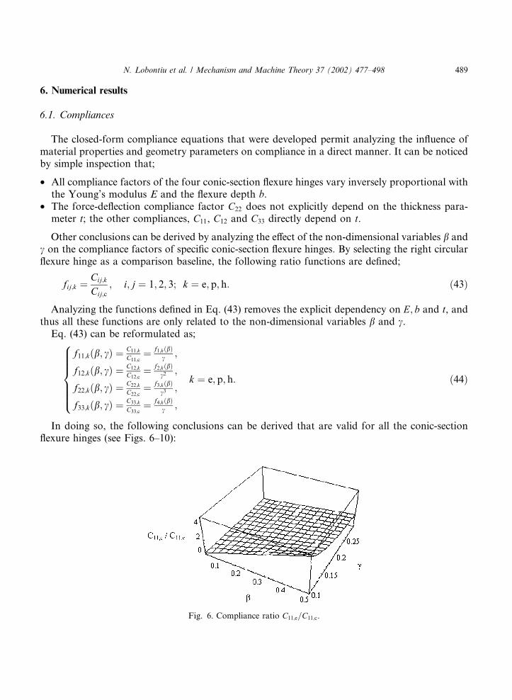
Fig. 6. Compliance ratio C11;e=C11;c.
N. Lobontiu et al. / Mechanism and Machine Theory 37 (2002) 477–498 489

Fig. 7. Compliance ratios C11;k=C11;c: (a) elliptic flexures; (b) parabolic flexures; (c) hyperbolic flexures; (d) comparison
of elliptic, parabolic and hyperbolic flexures for b ¼ 0:01; (e) f1;k functions.
490 N. Lobontiu et al. / Mechanism and Machine Theory 37 (2002) 477–498

Fig. 8. Compliance ratios C12;k=C12;c: (a) elliptic flexures; (b) parabolic flexures; (c) hyperbolic flexures; (d) comparison
of elliptic, parabolic and hyperbolic flexures for b ¼ 0:01; (e) f2;k functions.
N. Lobontiu et al. / Mechanism and Machine Theory 37 (2002) 477–498 491

Fig. 9. Compliance ratios C22;k=C22;c: (a) elliptic flexures; (b) parabolic flexures; (c) hyperbolic flexures; (d) comparison
of elliptic, parabolic and hyperbolic flexures for b ¼ 0:01; (e) f3;k functions.
492 N. Lobontiu et al. / Mechanism and Machine Theory 37 (2002) 477–498

Fig. 10. Compliance ratios C33;k=C33;c: (a) elliptic flexures; (b) parabolic flexures; (c) hyperbolic flexures; (d) comparison
of elliptic, parabolic and hyperbolic flexures for b ¼ 0:01; (e) f4;k functions.
N. Lobontiu et al. / Mechanism and Machine Theory 37 (2002) 477–498 493

Fig. 11. Compliance ratios C012;k=C
012;c: (a) elliptic flexures; (b) parabolic flexures; (c) hyperbolic flexures; (d) comparison
of elliptic, parabolic and hyperbolic flexures for b ¼ 0:01; (e) f 01;k functions.
494 N. Lobontiu et al. / Mechanism and Machine Theory 37 (2002) 477–498

Fig. 12. Compliance ratios C022;k=C
022;c: (a) elliptic flexures; (b) parabolic flexures; (c) hyperbolic flexures; (d) comparison
of elliptic, parabolic and hyperbolic flexures for b ¼ 0:01; (e) f 02;k functions.
N. Lobontiu et al. / Mechanism and Machine Theory 37 (2002) 477–498 495

• The elliptic, parabolic and hyperbolic flexure hinges are generally more compliant than thebaseline right circular flexure hinge, particularly for larger b; this is demonstrated by thenon-dimensional compliance ratios that were always greater than 1 in Figs. 6–10.
Fig. 13. Compliance ratios C033;k=C
033;c: (a) elliptic flexures; (b) parabolic flexures; (c) hyperbolic flexures; (d) comparison
of elliptic, parabolic and hyperbolic flexures for b ¼ 0:01; (e) f 03;k functions.
496 N. Lobontiu et al. / Mechanism and Machine Theory 37 (2002) 477–498
• The compliance ratios increase when b increases and c decreases (see Fig. 6 for a particularcase, but the note is valid for all other situations).
• The elliptic flexure hinges are more compliant than the parabolic, hyperbolic and circular flex-ures for smaller values of c and large values of b.
• The compliance ratios vary non-linearly with c (in a steep fashion for small c) which indicatesthat the elliptic parabolic and hyperbolic flexure hinges are more compliant than the circularones for large length-to-thickness ratios.
• The compliance ratios vary quasi-linearly with b.• When b and c are relatively small, the circular flexure hinges are more compliant than the other
conic-section flexure hinges.
6.2. Precision of rotation
The effect of E; b and t on the compliance factors that quantify the precision of rotation isidentical to the one described in the previous sub-section.
In order to analyze the influence of the non-dimensional variables b and c, the followingcompliance ratio functions are introduced;
f 0ij;k ¼
C0ij;k
C0ij;c
; i; j ¼ 1; 2; 3; k ¼ e; p; h: ð45Þ
Eq. (45) is reformulated as;
f 012;kðb; cÞ ¼
C012;k
C012;c
¼ f 01;kðbÞc2 ;
f 022;kðb; cÞ ¼
C022;k
C022;c
¼ f 02;kðbÞc3
f 033;kðb; cÞ ¼
C033;k
C033;c
¼ f 03;kðbÞ
c ;
8>>>>><>>>>>:
k ¼ e; p; h: ð46Þ
The elliptic, parabolic and hyperbolic flexure hinges are again compared to the right circularflexures baseline.
It can be seen (Figs. 11–13) that the hyperbolic flexures perform best in terms of preserving thecenter of rotation position.
7. Conclusions
The conic-section (circular, elliptic, parabolic, and hyperbolic) flexure hinges are presented in aunitary manner by means of their closed-form compliances. The flexibility and precision of ro-tation are the main subjects that are addressed. The analysis is performed in terms of two non-dimensional parameters and this allows comparing the performance of elliptic, parabolic andhyperbolic flexure hinges relative to circular flexure hinges. The elliptic, parabolic and hyperbolicflexure hinges (in this order) are more compliant than the circular ones for large length-to-thickness ratios. The hyperbolic flexures perform best in terms of preserving the center ofrotation position.
N. Lobontiu et al. / Mechanism and Machine Theory 37 (2002) 477–498 497

References
[1] J.M. Paros, L. Weisbord, How to design flexure hinges, Machine Design 25 (1965) 151–156.
[2] K.M. Ragulskis, M.G. Arutunian, A.V. Kochikian, M.Z. Pogosian, A study of fillet type flexure hinges and their
optimal design, Vibration Engineering 3 (1989) 447–452.
[3] T.S. Smith, V.G. Badami, J.S. Dale, Y. Xu, Elliptical flexure hinges, Review of Scientific Instruments 68 (3) (1997)
1474–1483.
[4] S. Smith, Flexures: Elements of Elastic Mechanisms, Gordon and Breach Science Publishers, New York, 2000.
[5] N. Lobontiu, J.S.N. Paine, E. Garcia, M. Goldfarb, Corner filleted flexure hinges, ASME Journal of Mechanical
Design 123 (2001) 346–352.
[6] W. Xu, T.G. King, Flexure hinges for piezo-actuator displacement amplifiers: flexibility, accuracy and stress
considerations, Precision Engineering 19 (1) (1996) 4–10.
[7] J.W. Ryu, D.-G. Gweon, Error analysis of a flexure hinge mechanism induced by machining imperfection, Precision
Engineering 21 (1997) 83–89.
[8] N. Lobontiu, J.S.N. Paine, E. O’Malley, M. Samuelson, Parabolic and hyperbolic flexure hinges: flexibility, motion
precision and stress characterization based on compliance closed-form equations, Precision Engineering (in press).
498 N. Lobontiu et al. / Mechanism and Machine Theory 37 (2002) 477–498