Embed Size (px)
DESCRIPTION
Deep Beam Flexure and Shear Design
Citation preview

A presentation on
Flexural & Shear Design ofFlexural & Shear Design of Deep Beam
Presented by
P N R (P t )Pragya N Roy (Peter)Structural Engineer
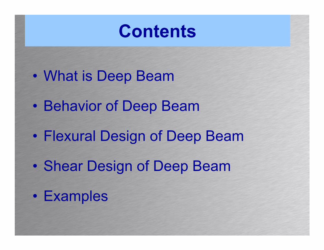
Contents
• What is Deep BeamWhat is Deep Beam
• Behavior of Deep BeamBehavior of Deep Beam
• Flexural Design of Deep BeamFlexural Design of Deep Beam
• Shear Design of Deep Beamg p
• Examplesp

What is Deep BeamWhat is Deep Beam• Large depth/thickness ratio • And shear span depth ratio
less than 2.5 for concentrated load
and less than 5.0 for distributed
load. • Where the shear span is the
clear span of the beam for distributed loaddistributed load

ApplicationApplication
• Pile CapPile Cap.• Bridge Girder.
W ll l b d ti l l d• Wall slabs under vertical loads.• Floors slabs under horizontal loads.• Some shear walls.

Behavior of Deep beamBehavior of Deep beam • Two-Dimensional Action.• Plane Section Do Not Remain Plane, in the deep
beam design. • The strain distribution is no longer linear.• The shear deformation cannot be neglected as in
the ordinary beam.• The stress distribution is not linear even in the
elastic stage. • At the ultimate limit state the shape of concrete
i bl k i b li hcompressive stress block is not parabolic shape again.

Behavior of Deep beamBehavior of Deep beam • The distribution of tensile stress at bottom
fiber is constant over the span.• Tensile stress in the bottom fiber at supportTensile stress in the bottom fiber at support
and at mid span is almost the same.• The tension reinforcement must be extended• The tension reinforcement must be extended
to the end of support.Th i t il t t th b tt• The maximum tensile stress at the bottom fiber is far exceed the magnitude of
i tcompressive stress.

Design Criteria for flexure in deep Beams
Simply Supported beams:• The ACI code does not specify a simplified
design procedureg p• ACI procedure for flexural analysis and
design of deep beams follows rigorous nondesign of deep beams follows rigorous non linear approach
• The simplified provisions presented in this• The simplified provisions presented in this section are based on the recommendations of the Euro International Concrete Committeethe Euro-International Concrete Committee (CEB).

Design Criteria for flexure in deep Beams
• A schematic stressA schematic stress distribution in a homogeneous deep beamhomogeneous deep beam having a span/depth ratio L /h = 1 0Ln/h 1.0
• It was experimentally observed that the momentobserved that the moment lever arm does not change significantly even after initialsignificantly even after initial cracking

Design Criteria for flexure in deep Beams
Nominal Resisting Moment,Mn = Asfy (moment arm jd)
The reinforcement area ‘As’ for flexure isAs = Mu/φfyjd ≥ 3√fc bd/fy ≥ 200bd/fyAs Mu/φfyjd ≥ 3√fc bd/fy ≥ 200bd/fy
The lever arm as recommended by CEBj 0 2( 2 ) f 1 l/h 2jd= 0.2(l+2h) for 1 ≤ l/h <2jd=0.6l for l/h <1l= Effective span measured from c/c.
The tension reinforcement has to be placed in thelower segment of beam height such that theg gsegment height is Y=0.25h-0.05l < 0.20h

Design Criteria for flexure in deep Beams

SHEAR DESIGN OF DEEP BEAM
• The shear design of deep beam is similar as shear design of ordinary beam.g y
• The difference is the concrete shear strength.• Limitation of ultimate shear force.• Horizontal and vertical stirrups distribution.
BASIC DESIGN EQUATIONBASIC DESIGN EQUATIONφVn ≥ Vu
• Vn = nominal shear strength• Vn = nominal shear strength• φVn = design shear strength• φ = strength reduction factor (0.85)φ g ( )• Vu = ultimate shear force, factored shear force

SHEAR DESIGN OF DEEP BEAM
• As shear design of ordinary beam, the shear force is resisted by the concrete component and by theshear reinforcement component, as follows :
Vn = Vc + Vswhere :• Vn = Nominal shear strength• Vc = Concrete shear strength without shear• Vc = Concrete shear strength without shear
reinforcement• Vs = shear reinforcement (stirrup) shear strength( p) g

CONCRETE SHEAR STRENGTHCONCRETE SHEAR STRENGTH
The concrete Shear strength of deep beam is taken asThe concrete Shear strength of deep beam is taken as
where :Vc = concrete shear strength (N)M lti t fl t (N )Mu = ultimate flexure moment (Nmm)Vu = ultimate shear force (N)f’c = concrete cylinder strength (MPa)d = effective depthpbw = width of beam webρw = longitudinal reinforcement ratio

CONCRETE SHEAR
Or ,the concrete shear strength can be determined
STRENGTHOr ,the concrete shear strength can be determined
as :
The maximum limit of concrete shear strength is :s

CONCRETE SHEAR STRENGTH
The section must be enlarged if the ultimate shear force does not follow the condition below :
Or,

STIRRUP SHEAR STRENGTHSTIRRUP SHEAR STRENGTH
The strength of horizontal and vertical shear e st e gt o o o ta a d e t ca s eareinforcements is :

LIMITS OF SHEAR REINFORCEMENT
The minimum shear reinforcement area is :The minimum shear reinforcement area is :
Av−min = 0.0015 (bsv)
Avh−min = 0.0025 (bsh)where :where :
Av-min = minimum vertical stirrupsA h i = minimum horizontal stirrupsAvh-min = minimum horizontal stirrups
b = width of beami f ti l tisv = spacing of vertical stirrups
sh = spacing of horizontal stirrups

MAXIMUM SPACING OF SHEAR REINFORCEMENTREINFORCEMENT
The maximum spacing of shear reinforcement is :p g

CRITICAL SECTION IN DEEP BEAM
The critical section to determines the ultimate shear force in the deep beam is :

STEP – BY – STEP PROCEDURE
The followings are the step – by – step procedure used in the shear design for deep beam, as follows :
Determine the critical section to calculate the ultimate shear force Vu.

STEP – BY – STEP PROCEDURESTEP BY STEP PROCEDURE
Check the ultimate shear force, enlarge the section if the condition is not achieved.

STEP – BY – STEP PROCEDURESTEP BY STEP PROCEDURE
Calculate the concrete shear strength Vc:
STEP – BY – STEP PROCEDURE
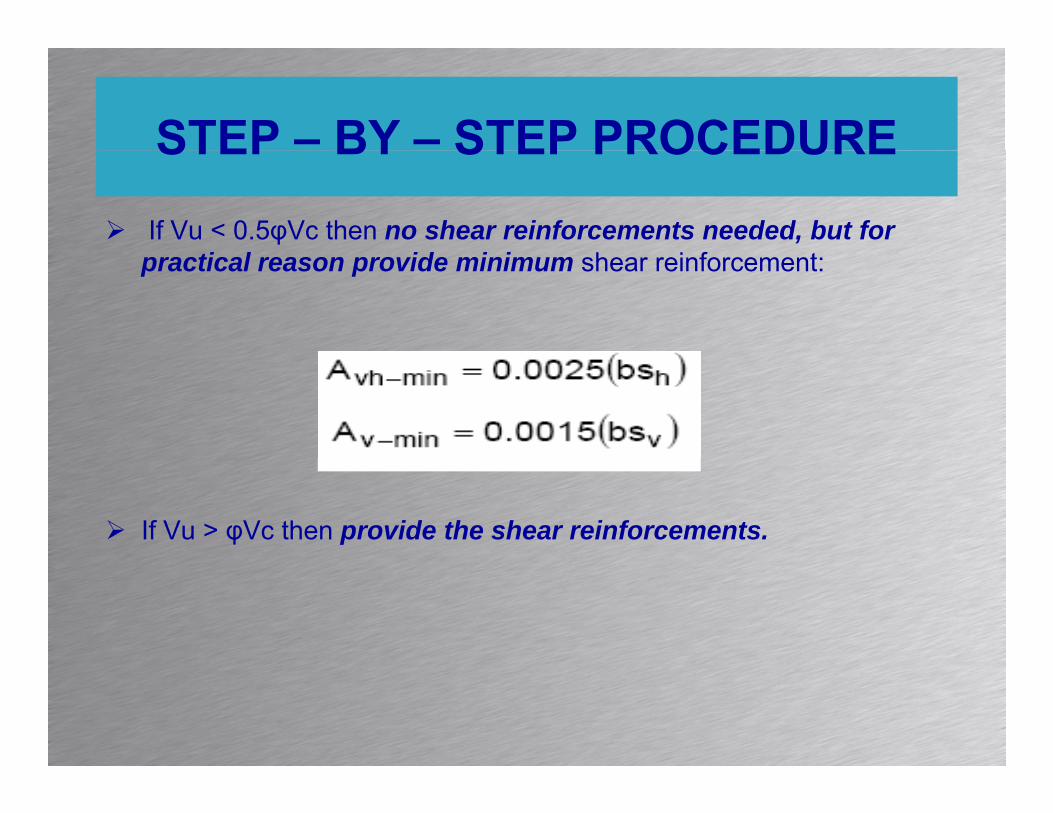
If Vu < 0.5φVc then no shear reinforcements needed, but for ti l id i i h i f t
STEP BY STEP PROCEDURE
practical reason provide minimum shear reinforcement:
If Vu > φVc then provide the shear reinforcements.

STEP – BY – STEP PROCEDURE
Calculate the ultimate shear force carried by the stirrups Vs
STEP BY STEP PROCEDURE
Calculate the ultimate shear force carried by the stirrups Vs.
Ch th ti l d h i t l ti til th diti Choose the vertical and horizontal stirrups until the condition achieved.

STEP – BY – STEP PROCEDURE
Check the spacing of shear reinforcement sv and sh
STEP BY STEP PROCEDURE
Check the spacing of shear reinforcement sv and sh.
If necessary check the chosen shear reinforcements for the basic design equation for shear design.

STEP – BY – STEP PROCEDURESTEP BY STEP PROCEDURE
The design procedure above is repeats until the basic design equation for shear design is achievedequation for shear design is achieved

Example: Design ProblemExample: Design Problem
Flexural Design of aFlexural Design of a Simply Supported Beam

Example: Design ProblemExample: Design Problem
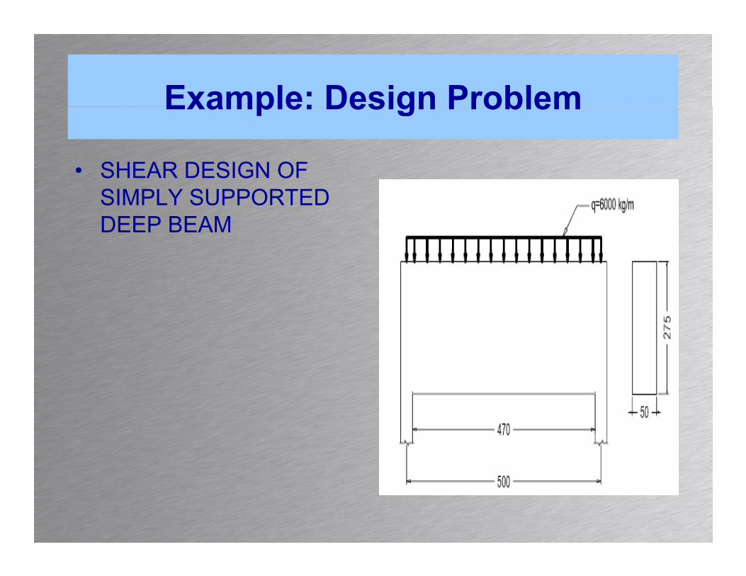
• MATERIAL • DIMENSIONMATERIAL• Concrete strength = K
– 300
DIMENSION• b = 500 mm• h = 2750 mm
• Steel grade = Grade 400
h = 2750 mm• Concrete cover = 50
mm• Concrete cylinder
strength = f'c = 0.83×
mm• d = 2700 mm
30 = 24.9 MPa• β1 = 0.85

Example: Design ProblemExample: Design Problem
• Design ForceDesign ForceMu=1.4((1/8)*qL^2
1 4((1/8)*6000*5^2= 1.4((1/8)*6000*5^2=26250 kgm
Deep Beam CheckingL /d = 4700/2700=1 74Ln/d 4700/2700 1.74Where, 1.0 ≤ 1.74 ≤ 5.0 Deep beam action

Example: Design ProblemExample: Design Problem
• Lever Armjd = 0.2(L + 2h)= 0.2(5000 + 2(2750))
=2100mmPositive ReinforcementMu = 262500000Nmm

Example: Design ProblemExample: Design Problem
Example: Design ProblemExample: Design Problem
• SHEAR DESIGN OF SIMPLY SUPPORTED DEEP BEAM

Example: Design ProblemExample: Design Problem
• MATERIAL • DIMENSIONMATERIAL• Concrete strength = K
– 300
DIMENSION• b = 500 mm• h = 2750 mm
• Steel grade = Grade 240
h = 2750 mm• Concrete cover = 50
mm• Concrete cylinder
strength = f'c = 0.83×
mm• d = 2700 mm
30 = 24.9 MPa• β1 = 0.85

Example: Design ProblemExample: Design Problem
• Design ForceDesign ForceX =1.5Ln=0.15x4700 =705mmV =1 4(10770)= 15078 kgVu =1.4(10770)= 15078 kgLimitation Checking
The Section is not enlarged.

Example: Design ProblemExample: Design Problem
• Concrete Shear StrengthConcrete Shear Strength

Example: Design ProblemExample: Design Problem
• Design of StirrupsDesign of Stirrups
V 150780 0 5*Φ*V 872161Vu= 150780 < 0.5*Φ*Vc =872161Provide minimum web reinforcementFor horizontal and vertical stirrups we
choose 2 legs Φ10.gAv=2((1/4)*π Φ2 =2((1/4)* π*102 =157mm2

Example: Design ProblemExample: Design Problem

Example: Design ProblemExample: Design Problem
• Reinforcement arrangementReinforcement arrangement

ReferencesReferences
• Reinforced Concrete by E G NawyReinforced Concrete by E. G. Nawy• http://www.asdipsoft.com/Deep-bm.htm

THANK YOUTHANK YOU