Embed Size (px)
Citation preview
1 © 2005 Nokia V1-Filename.ppt / yyyy-mm-dd / Initials
Company Confidential
Flexi EDGE BTS Configurations•Minimum and maximum configurations•Capacity expansion steps •BTS cabling•Combining options
2 © 2005 Nokia V1-Filename.ppt / yyyy-mm-dd / Initials
Company Confidential
Objectives
After the module the participant will be able to:
• Describe minimum and maximum configurations
• Give a typical growth path, and show how the hardware should be laid out to achieve this
• Give examples of the Smart Radio Concept (SRC) features Note: Some of these will be developed after the initial S/W release
3 © 2005 Nokia V1-Filename.ppt / yyyy-mm-dd / Initials
Company Confidential
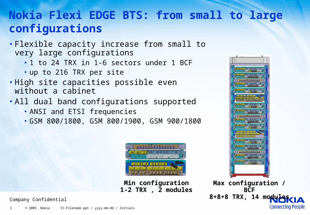
Nokia Flexi EDGE BTS: from small to large configurations• Flexible capacity increase from small to very
large configurations • 1 to 24 TRX in 1-6 sectors under 1 BCF • up to 216 TRX per site
• High site capacities possible even without a cabinet
• All dual band configurations supported• ANSI and ETSI frequencies• GSM 800/1800, GSM 800/1900, GSM 900/1800
Min configuration1-2 TRX , 2 modules
Max configuration / BCF
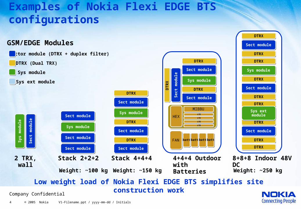
8+8+8 TRX, 14 modules
4 © 2005 Nokia V1-Filename.ppt / yyyy-mm-dd / Initials
Company Confidential
Sys m
od
ule
Sys m
od
ule
Sect
mod
ule
Sect
mod
ule
Sect moduleSect module
Sect moduleSect module
Sys moduleSys module
Sect moduleSect module
Stack 2+2+2 8+8+8 Indoor 48V DC
4+4+4 Outdoor with Batteries
2 TRX, wall
Stack 4+4+4
Examples of Nokia Flexi EDGE BTS configurations
DTRX
DTRX
DTRX
DTRX
DTRX
DTRX
DTRX
DTRX
DTRX
Sys ext moduleSys ext module
Sys module
Sys ext module
DTRX (Dual TRX)
Sector module (DTRX + duplex filter)
GSM/EDGE Modules
DTRX
DTRX
DTRX
Weight: ~150 kg
Low weight load of Nokia Flexi EDGE BTS simplifies site construction work
Weight: ~100 kg Weight: ~250 kg
DTRX
MIBBU
HEXLTE
LTE
LTE
LTE
FAN batt batt batt batt
DTRXDTR
X
Sect moduleSect module
Sect moduleSect module
Sect moduleSect module
Sys moduleSys module
Sect moduleSect module
Sect moduleSect module
Sys moduleSys module
Sect
mod
ule
Sect
mod
ule
Sect moduleSect module
Sect moduleSect module
Sect moduleSect module
Sys moduleSys module
5 © 2005 Nokia V1-Filename.ppt / yyyy-mm-dd / Initials
Company Confidential
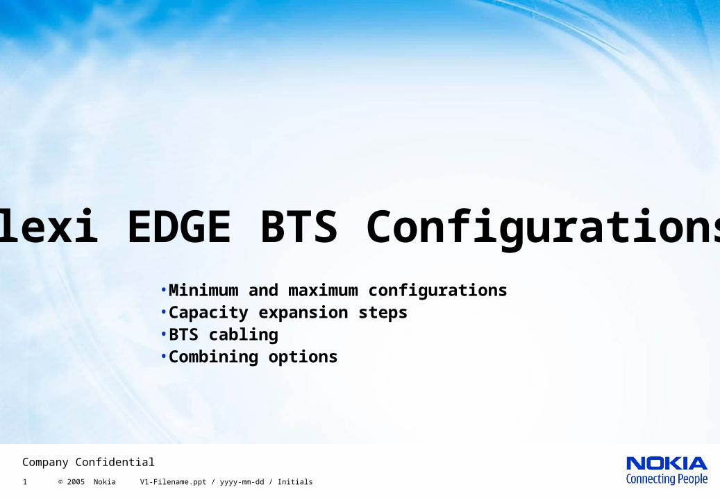
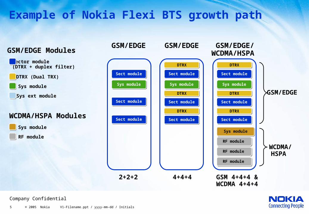
GSM 4+4+4 &WCDMA 4+4+4
WCDMA/HSPA Modules
2+2+2 4+4+4
GSM/EDGE
GSM/EDGE
GSM/EDGE/WCDMA/HSPA
GSM/EDGE
WCDMA/HSPA
RF module
DTRX
DTRX
DTRX
Example of Nokia Flexi BTS growth path
Sys module
Sys ext module
DTRX (Dual TRX)
Sector module (DTRX + duplex filter)
GSM/EDGE Modules
Sys module
RF moduleSys module
RF module
RF module
Sect moduleSect module
Sys moduleSys module
Sect moduleSect module
Sect moduleSect module
Sect moduleSect module
Sys moduleSys module
Sect moduleSect module
Sect moduleSect module
DTRX
DTRX
DTRX
Sect moduleSect module
Sys moduleSys module
Sect moduleSect module
Sect moduleSect module
6 © 2005 Nokia V1-Filename.ppt / yyyy-mm-dd / Initials
Company Confidential
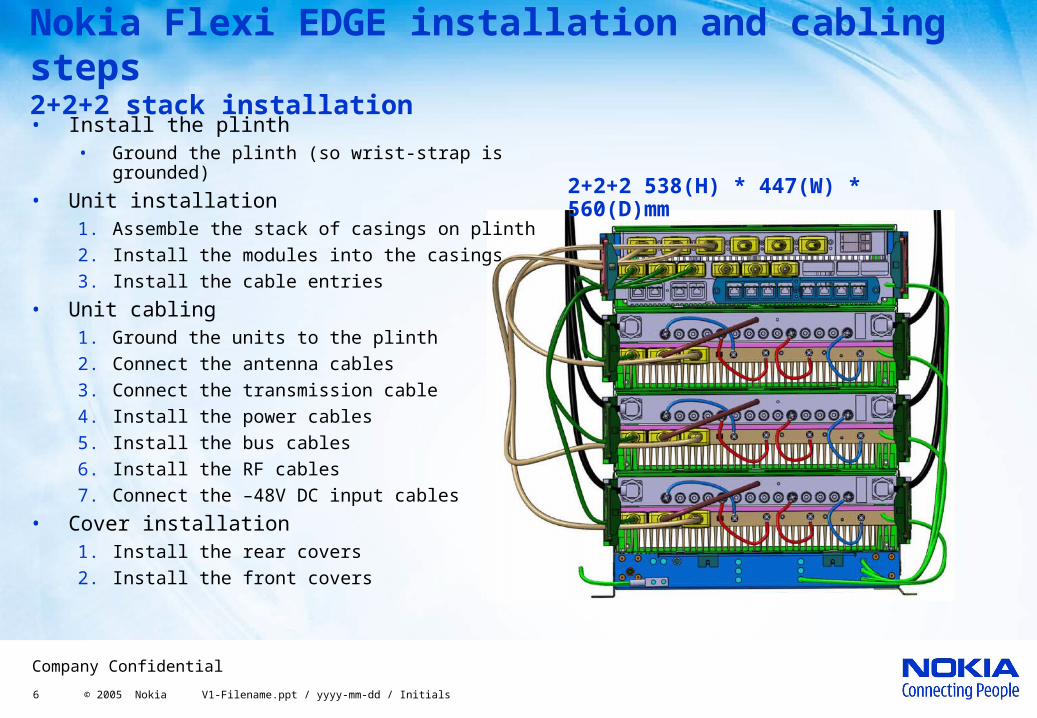
Nokia Flexi EDGE installation and cabling steps 2+2+2 stack installation• Install the plinth
• Ground the plinth (so wrist-strap is grounded)
• Unit installation1. Assemble the stack of casings on plinth
2. Install the modules into the casings
3. Install the cable entries
• Unit cabling1. Ground the units to the plinth
2. Connect the antenna cables
3. Connect the transmission cable
4. Install the power cables
5. Install the bus cables
6. Install the RF cables
7. Connect the –48V DC input cables
• Cover installation1. Install the rear covers
2. Install the front covers
2+2+2 538(H) * 447(W) * 560(D)mm
7 © 2005 Nokia V1-Filename.ppt / yyyy-mm-dd / Initials
Company Confidential
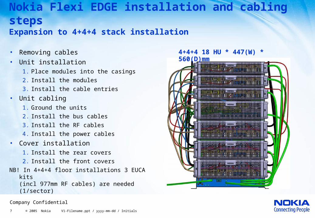
Nokia Flexi EDGE installation and cabling steps Expansion to 4+4+4 stack installation
• Removing cables
• Unit installation1. Place modules into the casings
2. Install the modules
3. Install the cable entries
• Unit cabling1. Ground the units
2. Install the bus cables
3. Install the RF cables
4. Install the power cables
• Cover installation1. Install the rear covers
2. Install the front covers
NB! In 4+4+4 floor installations 3 EUCA kits (incl 977mm RF cables) are needed (1/sector)
4+4+4 18 HU * 447(W) * 560(D)mm
8 © 2005 Nokia V1-Filename.ppt / yyyy-mm-dd / Initials
Company Confidential
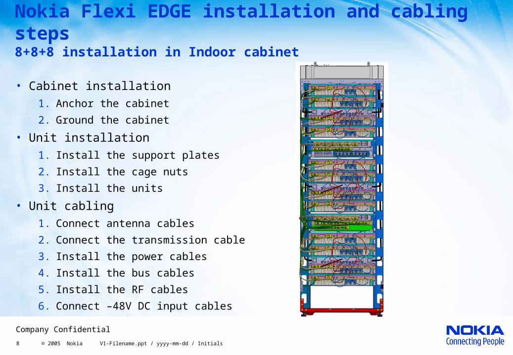
Nokia Flexi EDGE installation and cabling steps 8+8+8 installation in Indoor cabinet
• Cabinet installation1. Anchor the cabinet
2. Ground the cabinet
• Unit installation1. Install the support plates
2. Install the cage nuts
3. Install the units
• Unit cabling1. Connect antenna cables
2. Connect the transmission cable
3. Install the power cables
4. Install the bus cables
5. Install the RF cables
6. Connect –48V DC input cables
9 © 2005 Nokia V1-Filename.ppt / yyyy-mm-dd / Initials
Company Confidential
• Dual TRX module can be implemented in capacity mode or coverage mode
• In capacity mode both TRXs of the DTRX are used for capacity
• Four combining options for capacity mode:• By-pass combining
• 2-way wideband combining (WBC)
• 4-way wideband combining (WBC)
• 6-way Remote Tune Combining (RTC)
Nokia Flexi EDGE BTS in capacity mode
10 © 2005 Nokia V1-Filename.ppt / yyyy-mm-dd / Initials
Company Confidential
LNA
LNA
Du
ple
xer
Du
ple
xer
LNA+ Multi-couple
r
LNA+ Multi-couple
r
Du
ple
xer
Du
ple
xer
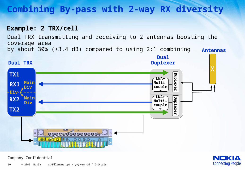
Combining By-pass with 2-way RX diversity
Dual TRX transmitting and receiving to 2 antennas boosting the coverage area by about 30% (+3.4 dB) compared to using 2:1 combining
Dual Duplexer Dual TRX
Example: 2 TRX/cell
TX1
RX1 MainDiv
RX2 MainDiv
TX2
Div
Antennas
X
11 © 2005 Nokia V1-Filename.ppt / yyyy-mm-dd / Initials
Company Confidential
Dual Duplexer
Antennas
X
TX1
RX1 MainDiv
RX2 MainDiv
TX2
Div
TX3
RX3 MainDiv
RX4 MainDiv
TX4
Div
LNA
LNA
Du
ple
xer
Du
ple
xer
LNA+ Multi-couple
r
LNA+ Multi-couple
r
Du
ple
xer
Du
ple
xer
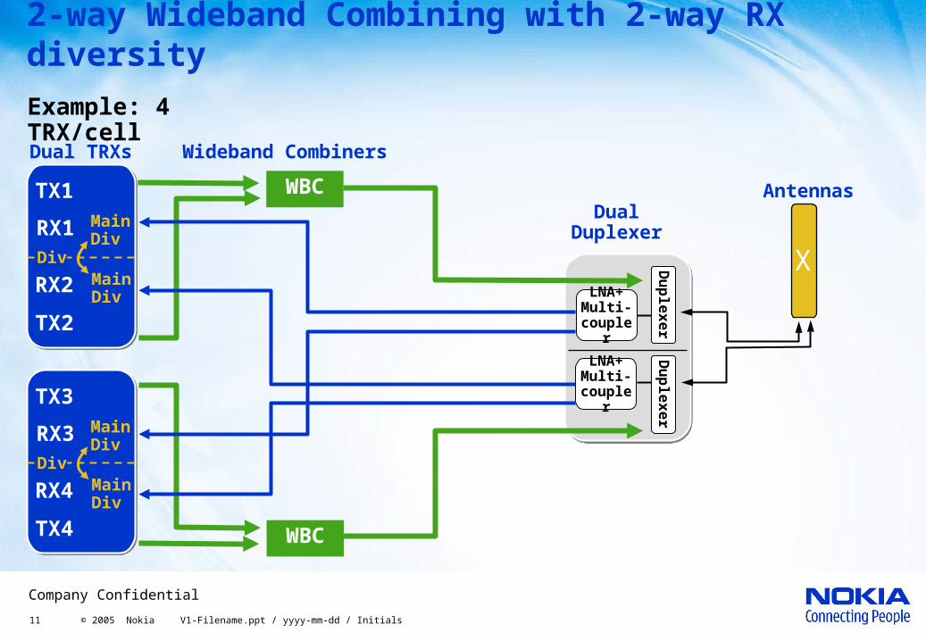
Example: 4 TRX/cell
WBC
Wideband CombinersDual TRXs
2-way Wideband Combining with 2-way RX diversity
WBC
12 © 2005 Nokia V1-Filename.ppt / yyyy-mm-dd / Initials
Company Confidential
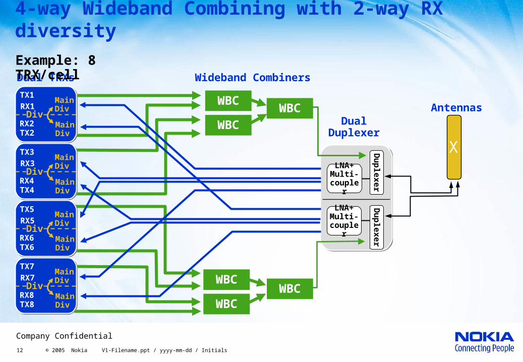
4-way Wideband Combining with 2-way RX diversity
Dual Duplexer
Antennas
X
LNA
LNA
Du
ple
xer
Du
ple
xer
WBCWBC
WBC
WBC
Wideband CombinersDual TRXs
WBC
WBC
TX1RX1
MainDiv
RX2 MainDivTX2
Div
TX3RX3
MainDiv
RX4 MainDivTX4
Div
TX5RX5
MainDiv
RX6 MainDivTX6
Div
TX7RX7
MainDiv
RX8 MainDivTX8
Div
LNA+ Multi-couple
r
LNA+ Multi-couple
r
Du
ple
xer
Du
ple
xer
Example: 8 TRX/cell
13 © 2005 Nokia V1-Filename.ppt / yyyy-mm-dd / Initials
Company Confidential
LNA+ Multi-couple
r
RX
filte
rCavitie
s
RX
filte
r
Du
ple
xer
LNA+ Multi-couple
r
1 X-pol Antenna
X
TX5RX5
MainDiv
RX6 MainDivTX6
DivTX3RX3
MainDiv
RX4 MainDivTX4
DivTX1RX1
MainDiv
RX2 MainDivTX2
Div
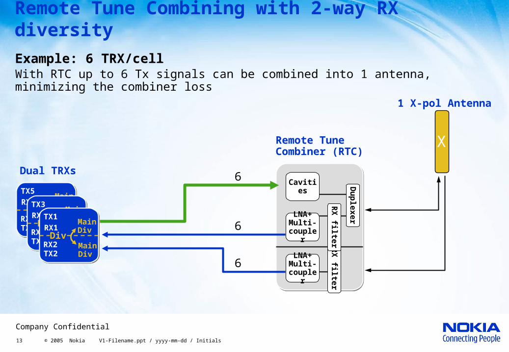
Remote Tune Combining with 2-way RX diversity
Example: 6 TRX/cell
Remote TuneCombiner (RTC)
Dual TRXs
With RTC up to 6 Tx signals can be combined into 1 antenna, minimizing the combiner loss
6
6
6
14 © 2005 Nokia V1-Filename.ppt / yyyy-mm-dd / Initials
Company Confidential
LNA+ Multi-couple
r
RX
filte
r
Cavities
RX
filte
r
Du
ple
xer
LNA+ Multi-couple
r
LNA+ Multi-couple
r
RX
filte
r
Cavities
RX
filte
r
Du
ple
xer
LNA+ Multi-couple
r
TX11RX11
MainDiv
RX12 MainDivTX12
DivTX9RX9
MainDiv
RX10 MainDivTX10
Div
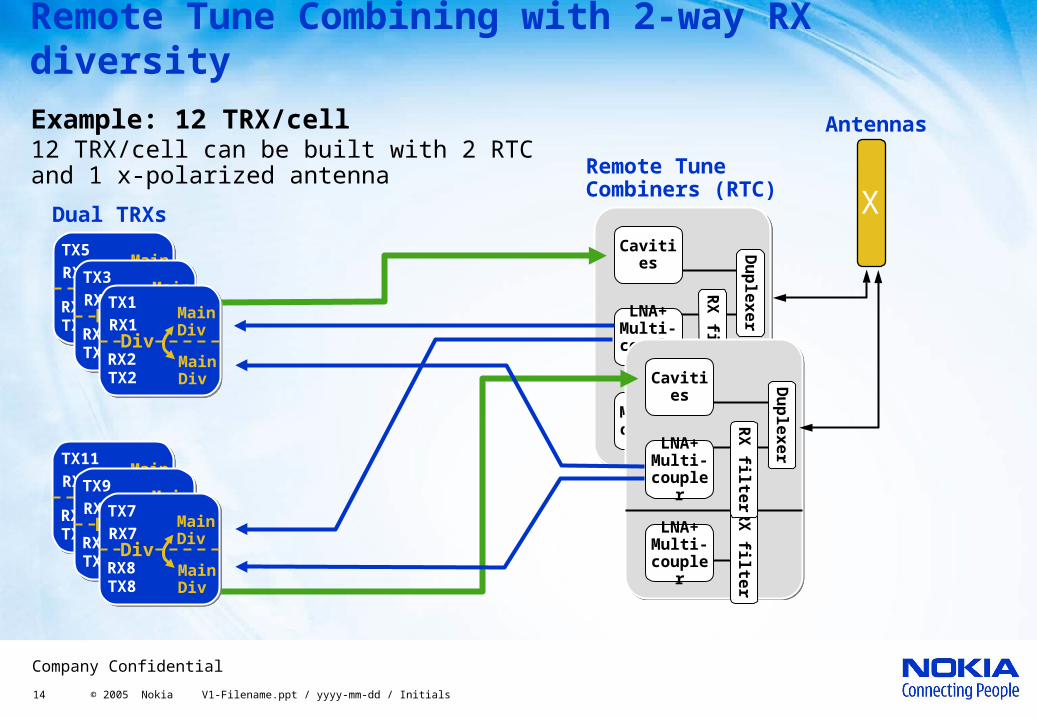
Remote Tune Combining with 2-way RX diversity
Example: 12 TRX/cell
Remote TuneCombiners (RTC)
12 TRX/cell can be built with 2 RTC and 1 x-polarized antenna
Antennas
XDual TRXs
TX5RX5
MainDiv
RX6 MainDivTX6
DivTX3RX3
MainDiv
RX4 MainDivTX4
DivTX1RX1
MainDiv
RX2 MainDivTX2
Div
TX7RX7
MainDiv
RX8 MainDivTX8
Div
15 © 2005 Nokia V1-Filename.ppt / yyyy-mm-dd / Initials
Company Confidential
Nokia Flexi EDGE BTS in coverage mode
• For boosting cell size and thereby reducing the number of sites, both downlink and uplink enhancement methods are implemented
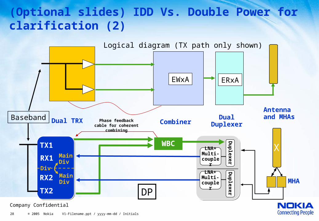
• Double Power TRX (DPTRX): • The output power of 2 TRX is combined in a synchronized manner within
Wideband Combiner (phase feedback to TRX from WBC) , doubling the TRX output power while using 1 TRX for capacity
• In DPTRX the combined 2 TRXs must be in the same Dual TRX module • DPTRX can be used in downlink limited cases or together with uplink
improvement methods, to increase cell coverage
• Five options for coverage mode:• DPTRX with 2-way UL diversity• DPTRX with 4-way UL diversity• Intelligent Downlink Diversity (IDD) with 2-way UL diversity• Nokia Smart Radio Concept (SRC)• DPTRX with Nokia SRC
16 © 2005 Nokia V1-Filename.ppt / yyyy-mm-dd / Initials
Company Confidential
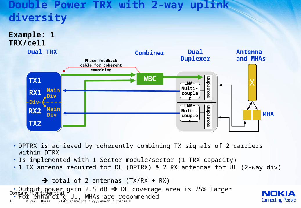
Double Power TRX with 2-way uplink diversity
Example: 1 TRX/cell
• DPTRX is achieved by coherently combining TX signals of 2 carriers within DTRX• Is implemented with 1 Sector module/sector (1 TRX capacity)• 1 TX antenna required for DL (DPTRX) & 2 RX antennas for UL (2-way div)
total of 2 antennas (TX/RX + RX) • Output power gain 2.5 dB DL coverage area is 25% larger• For enhancing UL, MHAs are recommended
Combiner Dual Duplexer
LNA+ Multi-couple
r
LNA+ Multi-couple
r
Du
ple
xer
Du
ple
xer
WBC
Dual TRX
TX1
RX1 MainDiv
RX2 MainDiv
TX2
Div
Phase feedback cable for coherent
combining
MHA
Antenna and MHAs
X
17 © 2005 Nokia V1-Filename.ppt / yyyy-mm-dd / Initials
Company Confidential
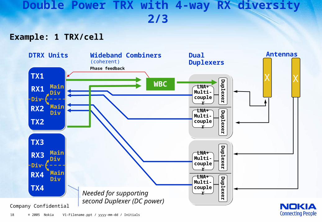
Double Power TRX with 4-way uplink diversity 1/3
• 4-way UL diversity balances the higher output power of DPTRX
• Is implemented with 2 Sector modules/sector
• 2 TX antenna required for DL (2*DPTRX) & 4 RX antennas for UL (4-way div)
total of 4 antennas (2 TX/RX + 2 RX)
• Output power and sensitivity gains are 2.5 dB coverage area is 25% larger
18 © 2005 Nokia V1-Filename.ppt / yyyy-mm-dd / Initials
Company Confidential
LNA+ Multi-couple
r
LNA+ Multi-couple
r
Du
ple
xer
Du
ple
xer
Phase feedback
LNA+ Multi-couple
r
LNA+ Multi-couple
r
Du
ple
xer
Du
ple
xer
TX3
RX3 MainDiv
RX4 MainDiv
TX4
Div
TX1
RX1 MainDiv
RX2 MainDiv
TX2
Div
Double Power TRX with 4-way RX diversity 2/3
Wideband Combiners(coherent)
Dual Duplexers
DTRX Units Antennas
Example: 1 TRX/cell
Needed for supporting second Duplexer (DC power)
WBC
X
X
19 © 2005 Nokia V1-Filename.ppt / yyyy-mm-dd / Initials
Company Confidential
Antennas
X
X
LNA+ Multi-couple
r
LNA+ Multi-couple
r
Du
ple
xer
Du
ple
xer
WBC
LNA+ Multi-couple
r
LNA+ Multi-couple
r
Du
ple
xer
Du
ple
xer
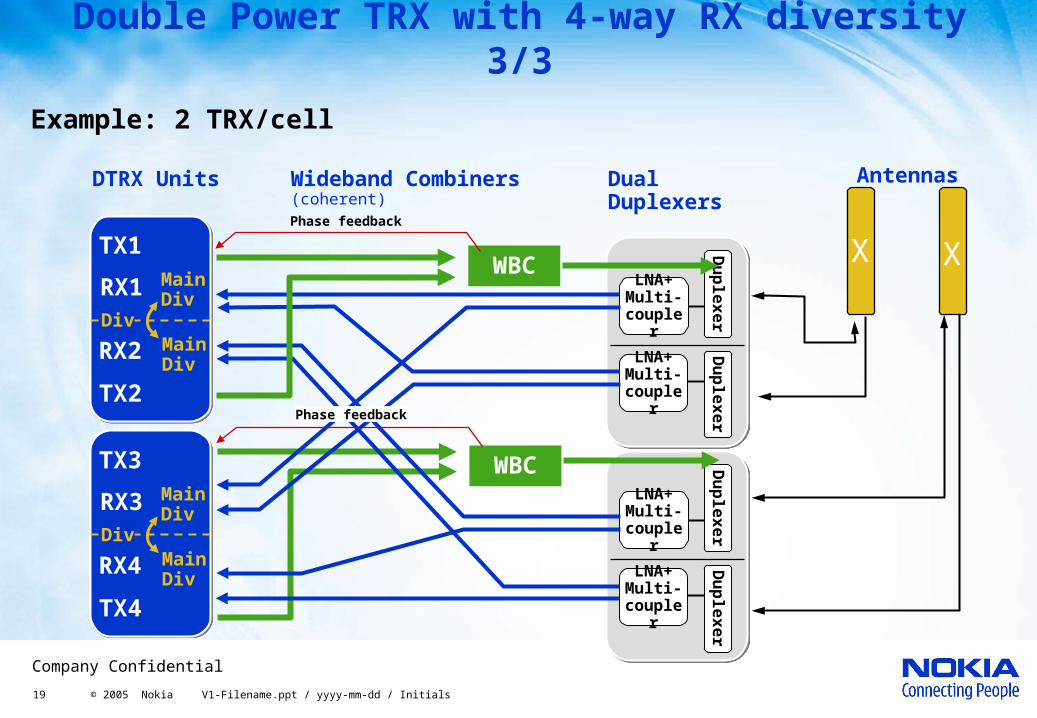
Wideband Combiners(coherent)
Dual Duplexers
DTRX Units
Double Power TRX with 4-way RX diversity 3/3
Example: 2 TRX/cell
WBCTX1
RX1 MainDiv
RX2 MainDiv
TX2
Div
TX3
RX3 MainDiv
RX4 MainDiv
TX4
Div
Phase feedback
Phase feedback
20 © 2005 Nokia V1-Filename.ppt / yyyy-mm-dd / Initials
Company Confidential
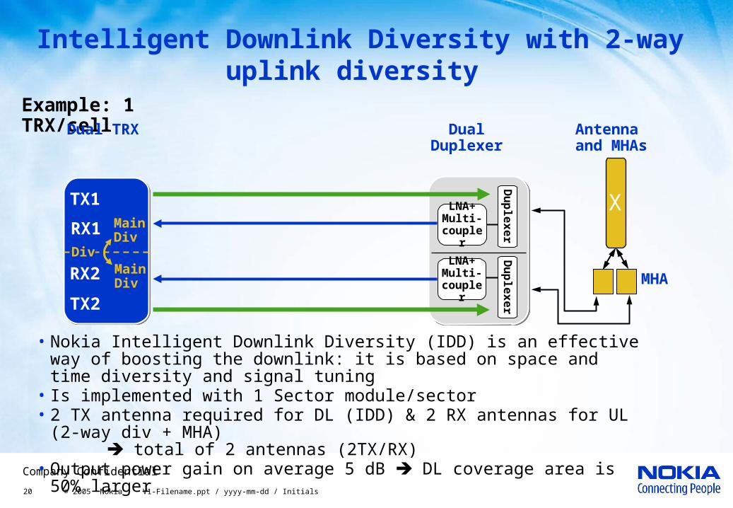
Intelligent Downlink Diversity with 2-way uplink diversity
Example: 1 TRX/cell
• Nokia Intelligent Downlink Diversity (IDD) is an effective way of boosting the downlink: it is based on space and time diversity and signal tuning
• Is implemented with 1 Sector module/sector• 2 TX antenna required for DL (IDD) & 2 RX antennas for UL (2-way div
+ MHA) total of 2 antennas (2TX/RX)
• Output power gain on average 5 dB DL coverage area is 50% larger
Dual Duplexer
LNA+ Multi-couple
r
LNA+ Multi-couple
r
Du
ple
xer
Du
ple
xer
Antenna and MHAs
X
Dual TRX
TX1
RX1 MainDiv
RX2 MainDiv
TX2
Div
MHA

21 © 2005 Nokia V1-Filename.ppt / yyyy-mm-dd / Initials
Company Confidential
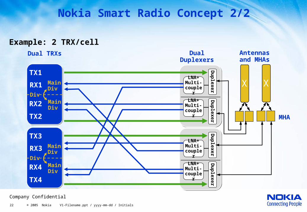
Nokia Smart Radio Concept 1/2
• Nokia Smart Radio Concept (SRC): Intelligent Downlink Diversity (IDD) with 4-way uplink diversity and MHA
• Is implemented with 2 Sector modules/sector
• Based on IDD and UL enhancement with MHA and 4-way UL diversity
• 4 TX antenna required for DL (2*IDD) & 4 RX antennas for UL (4-way div + MHA)
total of 4 antennas (4TX/RX)
• The improvement to coverage: average 5dB, in rural 8dB ) up to 50% less sites are needed
22 © 2005 Nokia V1-Filename.ppt / yyyy-mm-dd / Initials
Company Confidential
LNA+ Multi-couple
r
LNA+ Multi-couple
r
Du
ple
xer
Du
ple
xer
LNA+ Multi-couple
r
LNA+ Multi-couple
r
Du
ple
xer
Du
ple
xer
X
Dual Duplexers
Dual TRXs
TX1
RX1 MainDiv
RX2 MainDiv
TX2
Div
TX3
RX3 MainDiv
RX4 MainDiv
TX4
Div
Nokia Smart Radio Concept 2/2
Example: 2 TRX/cellAntennas and MHAs
MHA
X
23 © 2005 Nokia V1-Filename.ppt / yyyy-mm-dd / Initials
Company Confidential
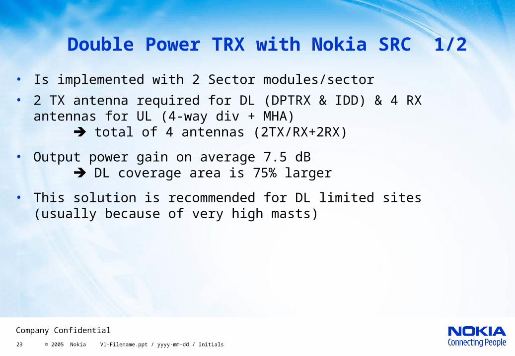
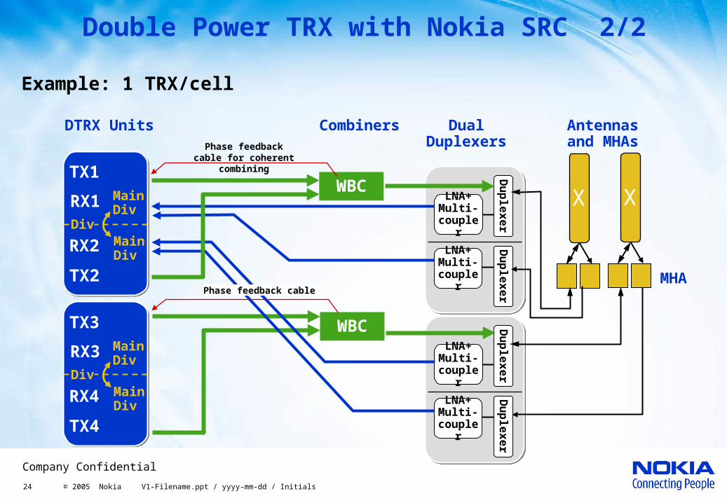
Double Power TRX with Nokia SRC 1/2
• Is implemented with 2 Sector modules/sector
• 2 TX antenna required for DL (DPTRX & IDD) & 4 RX antennas for UL (4-way div + MHA)
total of 4 antennas (2TX/RX+2RX)
• Output power gain on average 7.5 dB DL coverage area is 75% larger
• This solution is recommended for DL limited sites (usually because of very high masts)
24 © 2005 Nokia V1-Filename.ppt / yyyy-mm-dd / Initials
Company Confidential
LNA+ Multi-couple
r
LNA+ Multi-couple
r
Du
ple
xer
Du
ple
xer
WBC
LNA+ Multi-couple
r
LNA+ Multi-couple
r
Du
ple
xer
Du
ple
xer
Combiners Dual Duplexers
DTRX Units
Double Power TRX with Nokia SRC 2/2
Example: 1 TRX/cell
WBCTX1
RX1 MainDiv
RX2 MainDiv
TX2
Div
TX3
RX3 MainDiv
RX4 MainDiv
TX4
Div
Phase feedback cable
Phase feedback cable for coherent
combining X
Antennas and MHAs
MHA
X
25 © 2005 Nokia V1-Filename.ppt / yyyy-mm-dd / Initials
Company Confidential
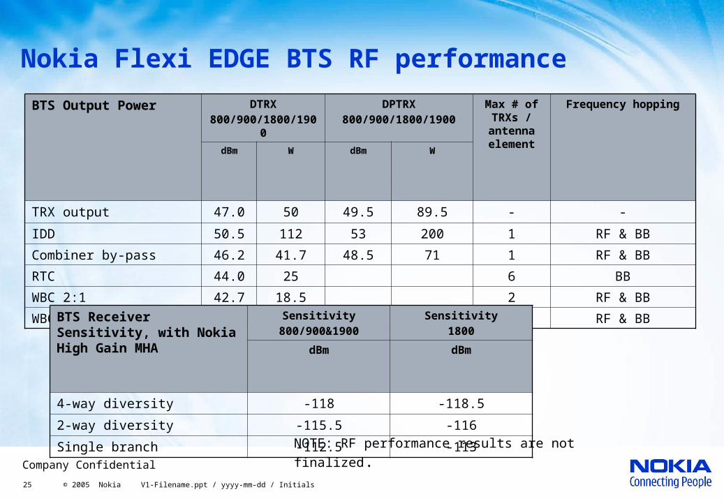
Nokia Flexi EDGE BTS RF performance
BTS Output Power DTRX800/900/1800/19
00
DPTRX800/900/1800/1900
Max # of TRXs /
antenna element
Frequency hopping
dBm W dBm W
TRX output 47.0 50 49.5 89.5 - -
IDD 50.5 112 53 200 1 RF & BB
Combiner by-pass 46.2 41.7 48.5 71 1 RF & BB
RTC 44.0 25 6 BB
WBC 2:1 42.7 18.5 2 RF & BB
WBC 4:1 39.4 8.7 4 RF & BBBTS Receiver Sensitivity, with Nokia High Gain MHA
Sensitivity800/900&1900
Sensitivity1800
dBm dBm
4-way diversity -118 -118.5
2-way diversity -115.5 -116
Single branch -112.5 -113NOTE: RF performance results are not finalized.
26 © 2005 Nokia V1-Filename.ppt / yyyy-mm-dd / Initials
Company Confidential
Nokia Flexi EDGE BTS output power
• BTS nominal output power values are measured at the Dual Duplexer module’s antenna connector (same as TOC figures of traditional cabinets)
• Output power values are defined with GMSK modulation. With 8-PSK modulation, values are 2 dB smaller.
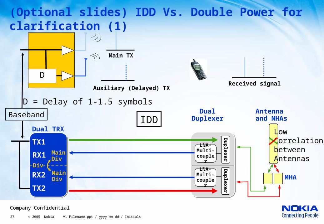
• Intelligent Downlink Diversity (IDD) doubles (~3 dB) the received signal power at the handset and multiple diversity gains add downlink by average of 1-2 dB, giving average 4.5 dB gain in total. Shown output power values are after air-combining without antenna gain.
• Combining options:• Combiner by-pass = No combining – 1 TRX to one antenna• WBC 2:1 = One stage Wide Band Combining – 1...2 TRXs to one antenna• WBC 4:1 = Two stage Wide Band Combining – 1...4 TRXs to one antenna• RTC 6:1 = Remote Tune Combining (cavity combining) – 1...6 TRXs to one antenna
• Output power values for RTC are given with 6 TRX and minimum channel spacing. With less TRXs and extended channel spacing, output power is up to 0.5 dB higher.
27 © 2005 Nokia V1-Filename.ppt / yyyy-mm-dd / Initials
Company Confidential
(Optional slides) IDD Vs. Double Power for clarification (1)
Auxiliary (Delayed) TXReceived signal
Main TX
D
D = Delay of 1-1.5 symbolsDual
Duplexer
LNA+ Multi-couple
r
LNA+ Multi-couple
r
Du
ple
xer
Du
ple
xer
Antenna and MHAs
Dual TRX
TX1
RX1 MainDiv
RX2 MainDiv
TX2
Div
MHA
Baseband
Low Correlationbetween Antennas
IDD
28 © 2005 Nokia V1-Filename.ppt / yyyy-mm-dd / Initials
Company Confidential
(Optional slides) IDD Vs. Double Power for clarification (2)
Baseband
EWxA ERxA
Logical diagram (TX path only shown)
CombinerDual
Duplexer
LNA+ Multi-couple
r
LNA+ Multi-couple
r
Du
ple
xer
Du
ple
xer
WBC
Dual TRX
TX1
RX1 MainDiv
RX2 MainDiv
TX2
Div
Phase feedback cable for coherent
combining
MHA
Antenna and MHAs
X
DP