Embed Size (px)
Citation preview

WWW.CONNECTRAC.COM02112021 PAGE 1
FLEX SYSTEM
INSTALLATION GUIDEA comprehensive guide to install Flex under carpet tile or on top of any flooring surface
WWW.CONNECTRAC.COM PAGE 1
FLEX SYSTEM

WWW.CONNECTRAC.COM02112021 PAGE 2
FLEX SYSTEM
WARNING: RISK OF FIRE OR ELECTRICAL SHOCK
• Read these assembly instructions prior to installation. • Flex must be anchored to the building floor for safe and proper use. Ensure use of proper anchors suitable for the application and environment. • The electrical supply connection to the building must be performed by a licensed electrician. Install per National Electric Code adopted in your location. • There are no user serviceable parts in this system. • Use provided hardware only. • Only use and install Flex in dry environments. • Do not place Top Cover seam directly over Power Hub terminals • Do not install this system over raised floors, across building expansion joints, or in areas where it will be subject to constant heavy loads. • For use with flooring materials between .1” and .35” (2.5mm-9mm ) thick. • Cap all unused connector openings with recommended termination system. • Power End Hub must be used to terminate power system. • Overall system length should not exceed 75’ (30m).
INSTALLATION BASICS
О Cut a 2” x 4” hole in your wall. О Find your Entrance Fitting and fish the flexible conduit through the hole. Fasten the plastic base to the floor. О Arrange your Powertracs and Power Hubs according to your layout. О Connect all modular components of the raceway together (ex. Powertracs and Power Hubs), and fasten the system to the floor with screws. Securely anchor the system at least every four feet using the holes provided. О At Receptacle Device or Hubcap locations, remove the “Remove Me” sticker from the Power Hub. Install the Receptacle Device, Hardwire Device or Hubcap as shown. О Completely surround the power distribution raceway with the transition ramping system. Position the transition ramping system down using some form of adhesive, and secure the ramps to the floor slab with 1/4” x 1 1/4” pin-drive anchors. О Trim the aluminum Top Cover and install in Powertrac between Receptacle Devices and Hubcaps. О Connect the flexible conduit to the building junction box. О Install carpet tile or suitable conformable flooring over the entire Flex assembly, cutting around devices.
REFER TO THE FOLLOWING PAGES FOR DETAILED INSTALLATION AND ASSEMBLY INFORMATION.
WWW.CONNECTRAC.COM PAGE 2
FLEX SYSTEM
WWW.CONNECTRAC.COM02112021 PAGE 3
FLEX SYSTEM
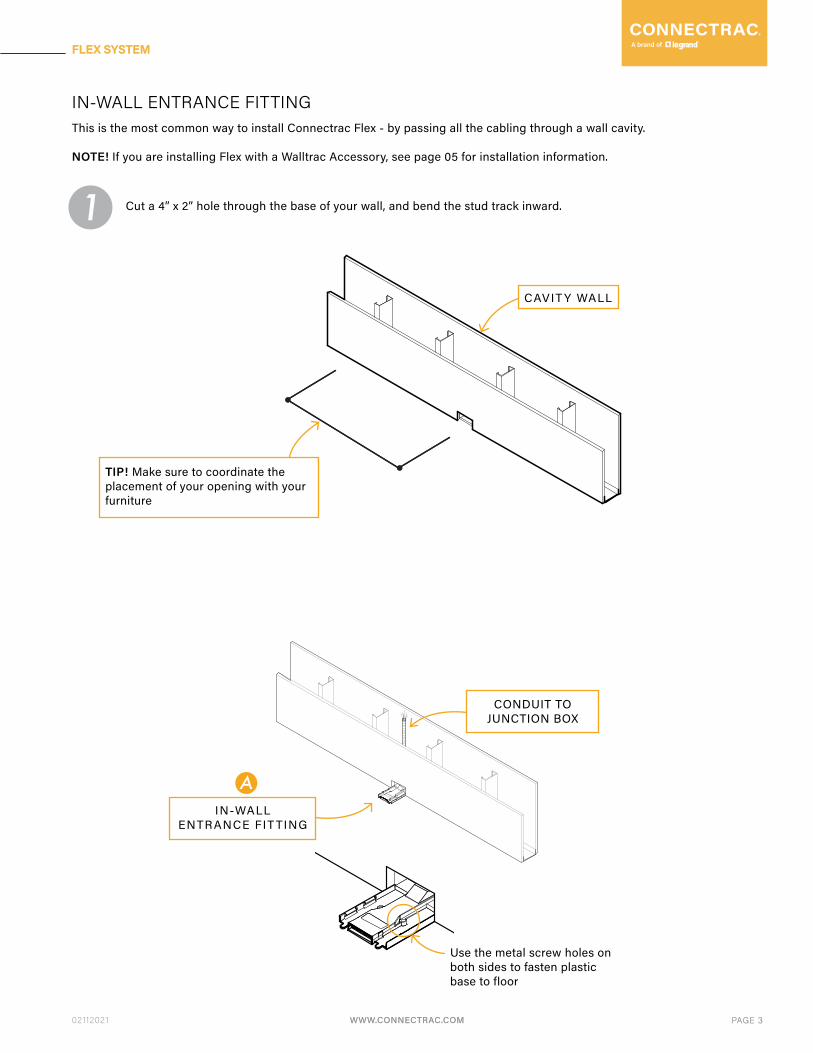
Cut a 4” x 2” hole through the base of your wall, and bend the stud track inward.
CAVIT Y WALL
IN-WALL ENTRANCE FITTINGThis is the most common way to install Connectrac Flex - by passing all the cabling through a wall cavity.
NOTE! If you are installing Flex with a Walltrac Accessory, see page 05 for installation information.
TIP! Make sure to coordinate the placement of your opening with your furniture
1
IN-WALLENTRANCE FIT TING
CONDUIT TO JUNCTION BOX
Use the metal screw holes on both sides to fasten plastic base to floor
A
WWW.CONNECTRAC.COM PAGE 3
FLEX SYSTEM

WWW.CONNECTRAC.COM02112021 PAGE 4
FLEX SYSTEM
Connect Entrance Fitting, Powertracs, Power Hubs, Power End Hubs, and devices to complete theFlex raceway system. Once connected, securely install them using appropriate fasteners for your flooring. 3
CONDUIT TO JUNCTION BOX
In-Wall Entrance Fitting
Raceway System
A
Power Hub These connect Powertracs. You can install power devices or Hubcaps into them.
Power End Hub A special hub that must be used at the end of each raceway.
Powertrac These come in various lengths. Make sure to coordinate the raceway with furniture in the space.
B
A
Z
Powertrac
Powertrac
Power Hub
PowerEnd Hub
B
For more information about Flex raceway system components , see page 15
Snap everything together... ... and fasten everything down.
*cl ick!**cl ick!*
Metal screw holes on bothsides to fasten plastic components to floor
Screw holes to fastenPowertrac to floor
SCAN FOR
INSTALL TIPS!
WWW.CONNECTRAC.COM PAGE 4
FLEX SYSTEM

WWW.CONNECTRAC.COM02112021 PAGE 5
FLEX SYSTEM
When using a Walltrac kit, your Surface-Mounted Entrance Fitting is installed in the same way,except the conduit passes through aluminum extrusions mounted to the wall.
There are several variations of Walltracs - for more information, refer to the instructions includedwith your Walltrac kit.
!
CONDUIT TO JUNCTION BOX
In-Wall Entrance Fitting
Raceway System
A
Power Hub These connect Powertracs. You can install power devices or Hubcaps into them.
Power End Hub A special hub that must be used at the end of each raceway.
Powertrac These come in various lengths. Make sure to coordinate the raceway with furniture in the space.
B
A
Z
Powertrac
Powertrac
Power Hub
PowerEnd Hub
BSCAN FOR
INSTALL TIPS!
For more information about Flex raceway system components , see page 15
Snap everything together... ... and fasten everything down.
*cl ick!**cl ick!*
Metal screw holes on bothsides to fasten plastic components to floor
Screw holes to fastenPowertrac to floor
WWW.CONNECTRAC.COM PAGE 5
FLEX SYSTEM
WWW.CONNECTRAC.COM02112021 PAGE 6
FLEX SYSTEM
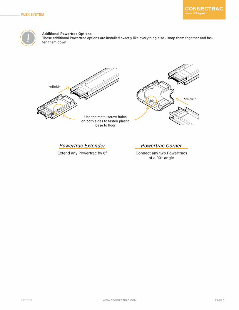
! Additional Powertrac Options These additional Powertrac options are installed exactly like everything else - snap them together and fas-ten them down!
Use the metal screw holeson both sides to fasten plastic
base to floor
*cl ick!*
*cl ick!*
Powertrac ExtenderExtend any Powertrac by 6”
Powertrac CornerConnect any two Powertracs
at a 90° angle
WWW.CONNECTRAC.COM PAGE 6
FLEX SYSTEM

WWW.CONNECTRAC.COM02112021 PAGE 7
FLEX SYSTEM
If you are NOT installing a power device or Hubcap into a Hub, do not remove the sticker over the central terminals.
When installing a Receptacle Device or Hubcap into a Hub or End Hub, remove the sticker that says “remove me” to expose the terminals. Then securely fasten the device or Hubcap down using the screws indicated.
4
Leave sticker ifNOT installing device
!
Remove sticker ifinstalling device
!
WWW.CONNECTRAC.COM PAGE 7
FLEX SYSTEM
WWW.CONNECTRAC.COM02112021 PAGE 8
FLEX SYSTEM
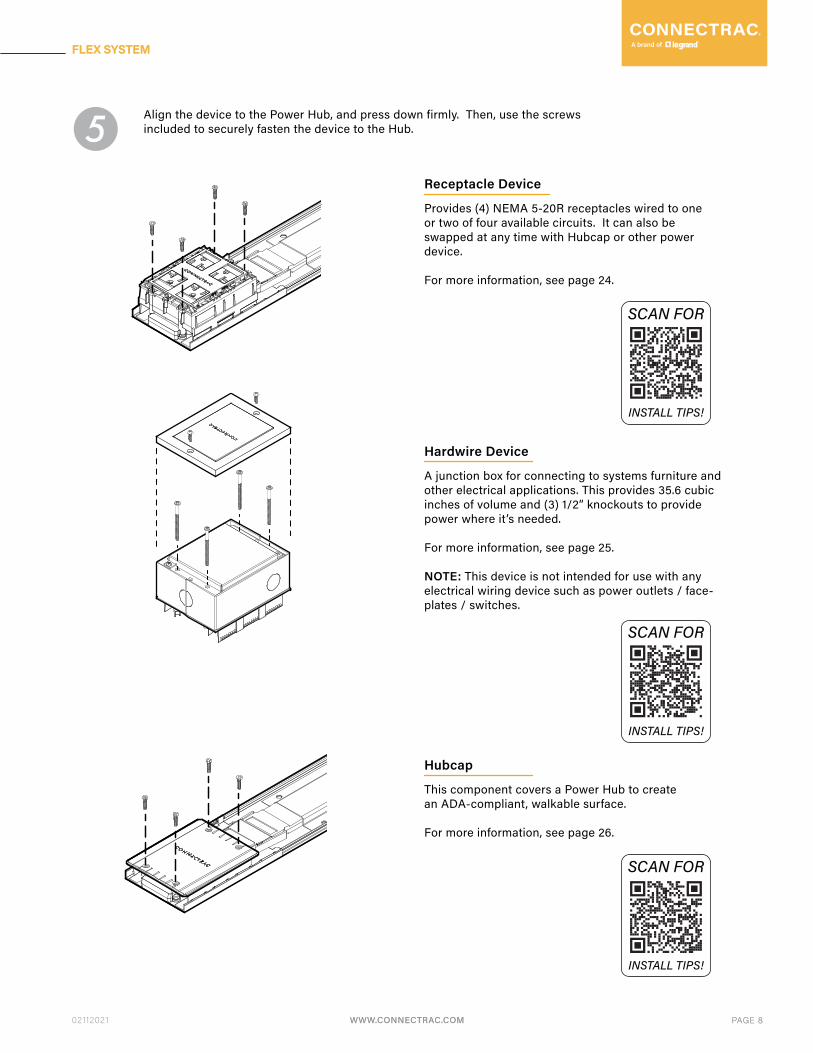
Align the device to the Power Hub, and press down firmly. Then, use the screws included to securely fasten the device to the Hub.5
Receptacle Device
Provides (4) NEMA 5-20R receptacles wired to oneor two of four available circuits. It can also be swapped at any time with Hubcap or other power device.
For more information, see page 24.
SCAN FOR
INSTALL TIPS!
Hubcap
This component covers a Power Hub to createan ADA-compliant, walkable surface.
For more information, see page 26.
SCAN FOR
INSTALL TIPS!
Hardwire Device
A junction box for connecting to systems furniture and other electrical applications. This provides 35.6 cubic inches of volume and (3) 1/2” knockouts to provide power where it’s needed.
For more information, see page 25.
NOTE: This device is not intended for use with any electrical wiring device such as power outlets / face-plates / switches.
SCAN FOR
INSTALL TIPS!
WWW.CONNECTRAC.COM PAGE 8
FLEX SYSTEM

WWW.CONNECTRAC.COM02112021 PAGE 9
FLEX SYSTEM
After the Flex raceway system is installed, completely surround it with the transition ramps.
Use construction adhesive to position the transition ramps around the raceway.
6
Secure the ramps to the floor slab with 1/4” x 1 1/4” pin-drive anchors.
!
WWW.CONNECTRAC.COM PAGE 9
FLEX SYSTEM

WWW.CONNECTRAC.COM02112021 PAGE 10
FLEX SYSTEM
!
!
Some Flex installations use alternate transition ramps for installation on top of any flooring. Refer to instructions included with these ramp extrusions for more information.
Some Flex installation use Datatracs for added low-voltage capacity. Use the included data managementclips to organize the data cabling.
TIP! Pull slightly from one end of the cable as you are installing top cover to ensure proper installation.
See capacity information on page 31
WWW.CONNECTRAC.COM PAGE 10
FLEX SYSTEM
WWW.CONNECTRAC.COM02112021 PAGE 11
FLEX SYSTEM
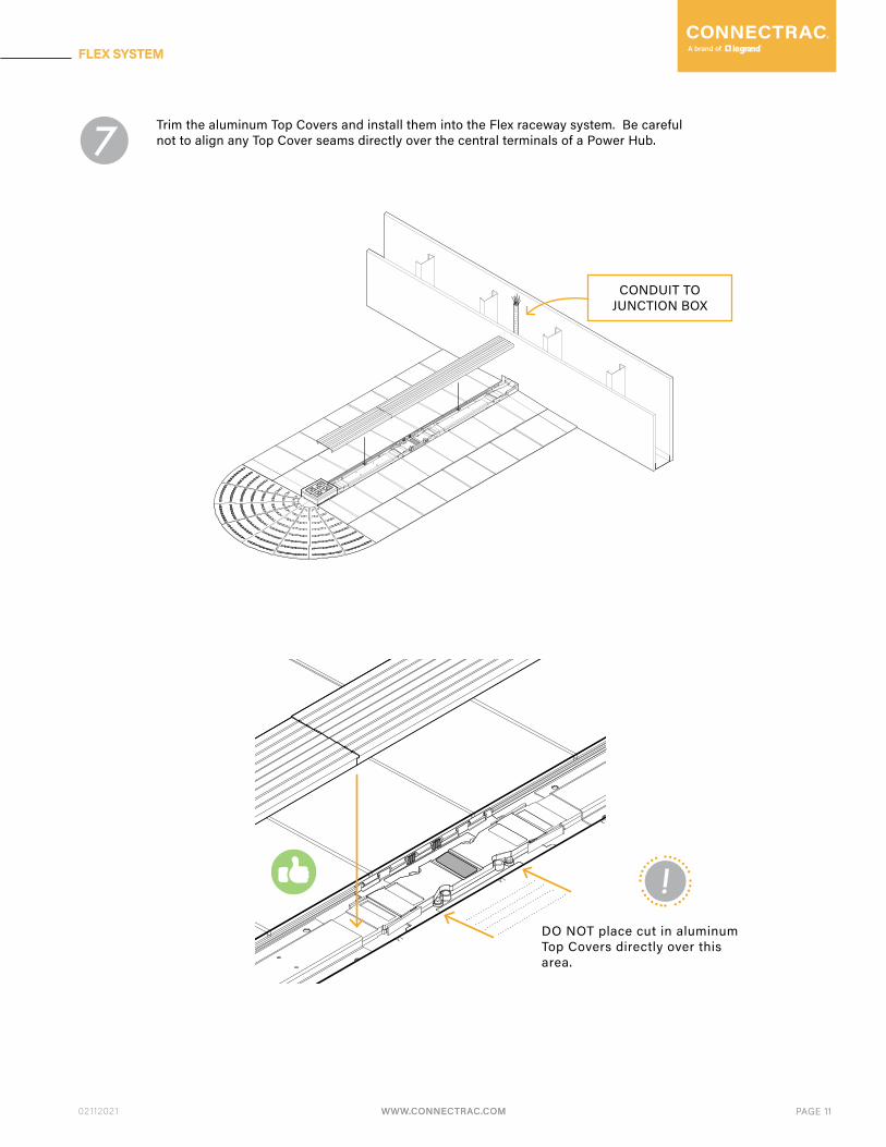
DO NOT place cut in aluminum Top Covers directly over this area.
CONDUIT TO JUNCTION BOX
Trim the aluminum Top Covers and install them into the Flex raceway system. Be careful not to align any Top Cover seams directly over the central terminals of a Power Hub. 7
!
WWW.CONNECTRAC.COM PAGE 11
FLEX SYSTEM

WWW.CONNECTRAC.COM02112021 PAGE 13
FLEX SYSTEM
Alternate Installation Method The Connectrac Flex ramping system is very flexible! The “flat” area of the Powertrac raceway can be extended as far as you’d like, just put the standard Transition Ramps at the edges of an “island” of flooring: !
FILL WITH APPROPRIATE SUBFLOOR MATERIAL
WWW.CONNECTRAC.COM PAGE 13
FLEX SYSTEM
WWW.CONNECTRAC.COM02112021 PAGE 14
FLEX SYSTEM
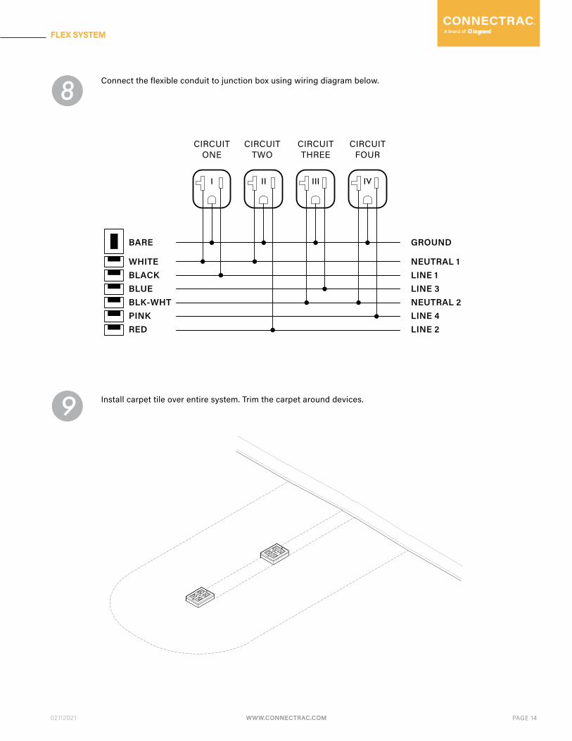
Connect the flexible conduit to junction box using wiring diagram below. 8
Install carpet tile over entire system. Trim the carpet around devices. 9
BARE
WHITEBLACKBLUEBLK-WHTPINKRED
GROUND
NEUTRAL 1LINE 1LINE 3NEUTRAL 2LINE 4LINE 2
CIRCUITONE
CIRCUITTWO
CIRCUITTHREE
CIRCUITFOUR
I II III IV
WWW.CONNECTRAC.COM PAGE 14
FLEX SYSTEM

WWW.CONNECTRAC.COM02112021 PAGE 15
FLEX SYSTEM
IN-WALL ENTRANCE FITTING
Specifications
Description
MaterialPC PlasticGalvanized Steel
Country of OriginTaiwan
CompliancecULus Listed to US & Canadian Safety Standards
Entrance Fittings are quick connectors that power the entire Flex raceway by converting the building mains power to the Flex 4-circuit power system. The In-Wall Entrance Fitting starts at the wall and is used when power/data cabling is running INSIDE the wall. It is attached to a flexible steel conduit that is pre-wired and available in two lengths (15’, 30’).The flexible conduit includes a 1/2” knockout fitting and typically connects to a junction box in the wall or ceiling.
Ordering Information
Associated Part Number Description
Simply order the Flex Codes you need for your raceway, and we’ll provide your system’s detailed part numbers on your bill of materials (BOM) and packing list.
A1.15, A1.30
CT.A1.1-15.4c
CT.A1.1-30.4c
ENTRANCE FITTING 1. IN-WALL w/ 15’ pre-wired conduit. 4-circuit.
ENTRANCE FITTING 1. IN-WALL w/ 30’ pre-wired conduit. 4-circuit.
Flex Codes*
*See Flex Spec Guides for Flex Code specification instructions.
0.56”
0.47”
4”
4.6”
WWW.CONNECTRAC.COM PAGE 15
FLEX SYSTEM

WWW.CONNECTRAC.COM02112021 PAGE 16
FLEX SYSTEM
SURFACE-MOUNTED ENTRANCE FITTING
Specifications
Ordering Information
Associated Part Number Description
Simply order the Flex Codes you need for your raceway, and we’ll provide your system’s detailed part numbers on your bill of materials (BOM) and packing list.
A2.3, A2.15, A2.30
CT.03-A2.1-03.4c
CT.03-A2.1-15.4c
CT.03-A2.1-30.4c
ENTRANCE FITTING 2. SURFACE-MOUNTED w/ 2’ Walltrac & 3’ pre-wired conduit. 4-circuit.
ENTRANCE FITTING 2. SURFACE-MOUNTED w/ 12’ Walltrac & 15’ pre-wired conduit. 4-circuit.
ENTRANCE FITTING 2. SURFACE-MOUNTED w/ 12’ Walltrac & 30’ pre-wired conduit. 4-circuit.
*See Flex Spec Guides for Flex Code specification instructions.
MaterialPC PlasticGalvanized Steel
Country of OriginTaiwan
CompliancecULus Listed to US & Canadian Safety Standards
Description
Entrance Fittings are quick connectors that power the entire Flex raceway by converting the building mains power to the Flex 4-circuit power system. The Surface-Mounted Entrance Fitting starts at the wall and is used when power/data cabling is running OUTSIDE the wall. It is attached to a flexible steel conduit that is pre-wired and available in three lengths (3’, 15’, 30’). The flexible conduit includes a 1/2” knockout fitting and typically connects to a junction box in the wall or ceiling.
Flex Codes*
4”
4”
0.47”
WWW.CONNECTRAC.COM PAGE 16
FLEX SYSTEM

WWW.CONNECTRAC.COM02112021 PAGE 17
FLEX SYSTEM
POWERTRAC
Measurements with Top Covers installed and typical data capacity shown:
B.ON seriesB.FX series(for installation under carpet tile) (for installation on top of any flooring surface)
Specifications
Description
Powertracs are pre-wired raceway segments available in five nominal lengths (2’, 3’, 4’, 5’, 6’) that come complete with Top Covers and Transition Ramps. Each Powertrac has modular connectors on each end that easily snap into an Entrance Fitting, Powertrac Extender, Powertrac Corner, Power Hub, or Power End Hub to build your Flex raceway.
0.66” 0.81”
4” 4”
0.43” 0.58”
0.6” 0.6”
Ordering Information
Associated Part Number Description
Simply order the Flex Codes you need for your raceway, and we’ll provide your system’s detailed part numbers on your bill of materials (BOM) and packing list.
B.FX series, B.ON series
CT.B.PT.4c.1-02
CT.B.PT.4c.1-03
CT.B.PT.4c.1-04
CT.B.PT.4c.1-05s
CT.B.PT.4c.1-06s
2’ RACEWAY POWERTRAC pre-wired straight segment. 4-circuit.
3’ RACEWAY POWERTRAC pre-wired straight segment. 4-circuit.
4’ RACEWAY POWERTRAC pre-wired straight segment. 4-circuit.
5’ RACEWAY POWERTRAC pre-wired straight segment. 4-circuit.
6’ RACEWAY POWERTRAC pre-wired straight segment. 4-circuit.
*See Flex Spec Guides for Flex Code specification instructions.
Flex Codes*
MaterialPC PlasticGalvanized Steel
Country of OriginTaiwan
CompliancecULus Listed to US & Canadian Safety Standards
4”
L
WWW.CONNECTRAC.COM PAGE 17
FLEX SYSTEM
WWW.CONNECTRAC.COM02112021 PAGE 18
FLEX SYSTEM
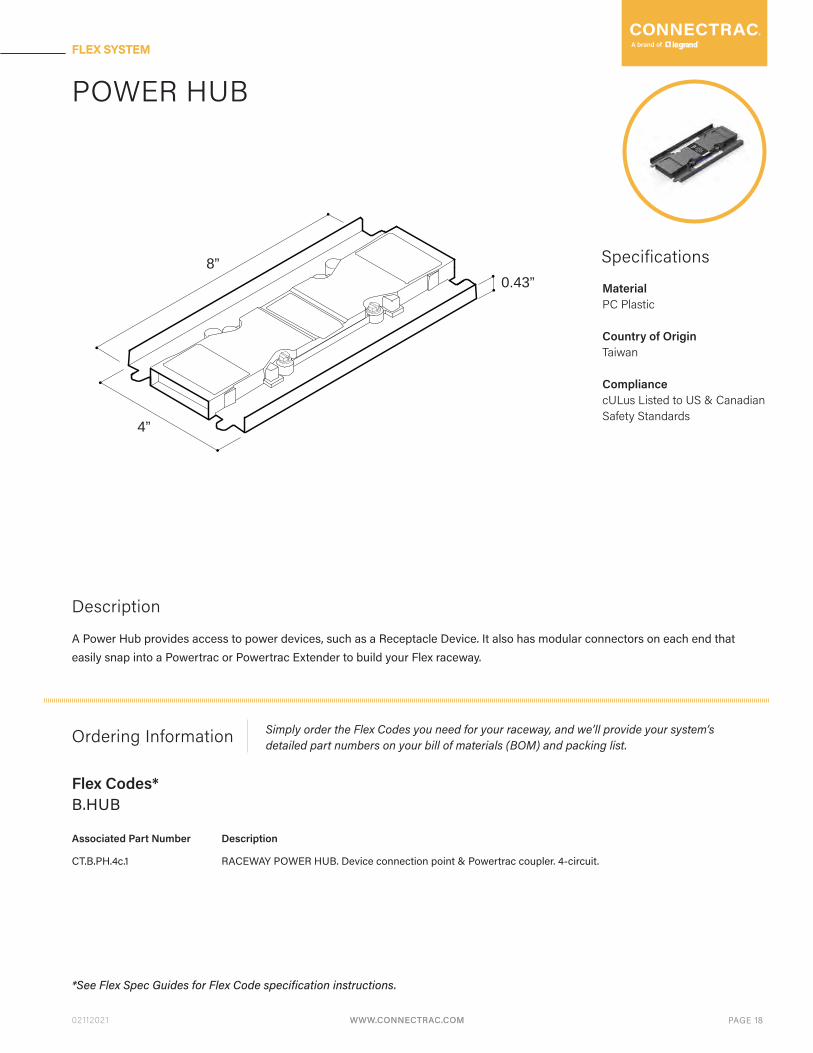
POWER HUB
Specifications
Description
A Power Hub provides access to power devices, such as a Receptacle Device. It also has modular connectors on each end that easily snap into a Powertrac or Powertrac Extender to build your Flex raceway.
Ordering Information
Associated Part Number Description
Simply order the Flex Codes you need for your raceway, and we’ll provide your system’s detailed part numbers on your bill of materials (BOM) and packing list.
B.HUB
CT.B.PH.4c.1 RACEWAY POWER HUB. Device connection point & Powertrac coupler. 4-circuit.
*See Flex Spec Guides for Flex Code specification instructions.
Flex Codes*
MaterialPC Plastic
Country of OriginTaiwan
CompliancecULus Listed to US & Canadian Safety Standards
4”
0.43”8”
WWW.CONNECTRAC.COM PAGE 18
FLEX SYSTEM

WWW.CONNECTRAC.COM02112021 PAGE 19
FLEX SYSTEM
POWER END HUB
Specifications
Description
A Power End Hub MUST be used to end every Flex raceway. It provides access to power devices, such as a Receptacle Device, and has a modular connector on one end that easily snaps into a Powertrac or Powertrac Extender.
Ordering Information
Associated Part Number Description
Simply order the Flex Codes you need for your raceway, and we’ll provide your system’s detailed part numbers on your bill of materials (BOM) and packing list.
B.HUB
CT.B.PHE.4c.1 RACEWAY POWER END HUB. Required to finish any powered run. 4-circuit.
*See Flex Spec Guides for Flex Code specification instructions.
Flex Codes*
MaterialPC Plastic
Country of OriginTaiwan
CompliancecULus Listed to US & Canadian Safety Standards
4”
4”
0.43”
WWW.CONNECTRAC.COM PAGE 19
FLEX SYSTEM

WWW.CONNECTRAC.COM02112021 PAGE 20
FLEX SYSTEM
Powertrac Corner
Specifications
Description
A Powertrac Corner connects Powertracs at a 90° angle. It also has modular connectors on each end that easily snap into a Powertrac or Powertrac Extender to build your Flex raceway.
Ordering Information
Associated Part Number Description
Simply order the Flex Codes you need for your raceway, and we’ll provide your system’s detailed part numbers on your bill of materials (BOM) and packing list.
B.FX series, B.ON series
CT.B.PT.4c-C90.1-FX
CT.B.PT.4c-C90.1-OM-DG
RACEWAY POWERTRAC CORNER: FLEX. 90 degree corner top cover & bottom. 4-circuit.
RACEWAY POWERTRAC CORNER: FLEX-ON/FLEX-MAX. 90 degree corner top cover & bottom. 4-ckt. DARK
GRAY.
Flex Codes*
MaterialPC PlasticPowder Coated Cast Aluminum
ColorDark Gray
Country of OriginTaiwanChina
CompliancecULus Listed to US & Canadian Safety Standards
WWW.CONNECTRAC.COM PAGE 20
FLEX SYSTEM

WWW.CONNECTRAC.COM02112021 PAGE 21
FLEX SYSTEM
POWERTRAC EXTENDER
Specifications
Description
A Powertrac Extender adds 6” to any standard Powertrac length. On one end it has modular connectors that easily snap into a Powertrac or Powertrac Extender, and the other end has modular connectors that connect to an Entrance Fitting, Hub, or End Hub.
Ordering Information
Associated Part Number Description
Simply order the Flex Codes you need for your raceway, and we’ll provide your system’s detailed part numbers on your bill of materials (BOM) and packing list.
B.FX series, B.ON series
CT.B.PT.4c-EXT.1-0.5 0.5’ RACEWAY POWERTRAC EXTENDER. 6” Powertrac raceway extension. 4-circuit.
Flex Codes*
MaterialPC Plastic
Country of OriginTaiwan
CompliancecULus Listed to US & Canadian Safety Standards
WWW.CONNECTRAC.COM PAGE 21
FLEX SYSTEM

WWW.CONNECTRAC.COM02112021 PAGE 22
FLEX SYSTEM
Specifications
Ordering Information
Description
RECEPTACLE DEVICE
MaterialPC Plastic
ColorDark Gray
Country of OriginTaiwan
CompliancecULus Listed to US & Canadian Safety Standards
Associated Part Number Description
Power devices quickly snap into any Power Hub or Power End Hub. They are all interchangeable and can be hot-swapped when desired. A Receptacle Device is a NEMA 5-20R quad power device available in a single/split circuit with 4 circuit options.
Simply order the Flex Codes you need for your raceway, and we’ll provide your system’s detailed part numbers on your bill of materials (BOM) and packing list.
C.PW1.11, C.PW1.22, C.PW1.33, C.PW1.44, C.PW1.12, C.PW1.34, C.PW1.14
CT.C.PW1.1-Q11-DG
CT.C.PW1.1-Q22-DG
CT.C.PW1.1-Q33-DG
CT.C.PW1.1-Q44-DG
CT.C.PW1.1-Q12-DG
CT.C.PW1.1-Q34-DG
CT.C.PW1.1-Q14-DG
CT.C.PW1cc.1-Q12-DG
CT.C.PW1cc.1-Q14-DG
CT.C.PW1cc.1-Q34-DG
POWER DEVICE 1. RECEPTACLE. 20A quad outlet. All circuit 1. DARK GRAY
POWER DEVICE 1. RECEPTACLE. 20A quad outlet. (2) circuit 1, (2) circuit 2. DARK GRAY
POWER DEVICE 1. RECEPTACLE. 20A quad outlet. (2) circuit 1, (2) circuit 4. DARK GRAY
POWER DEVICE 1. RECEPTACLE. 20A quad outlet. All circuit 2. DARK GRAY
POWER DEVICE 1. RECEPTACLE. 20A quad outlet. All circuit 3. DARK GRAY
POWER DEVICE 1. RECEPTACLE. 20A quad outlet. (2) circuit 3, (2) circuit 4. DARK GRAY
POWER DEVICE 1. RECEPTACLE. 20A quad outlet. All circuit 4. DARK GRAY
POWER DEVICE 1: TITLE 24 RECEPTACLE. 20A quad outlet. (2) circuit 1, (2) control ckt 2. DARK GRAY
POWER DEVICE 1: TITLE 24 RECEPTACLE. 20A quad outlet. (2) circuit 1, (2) control ckt 4. DARK GRAY
POWER DEVICE 1: TITLE 24 RECEPTACLE. 20A quad outlet. (2) circuit 3, (2) control ckt 4. DARK GRAY
*See Flex Spec Guides for Flex Code specification instructions.
Flex Codes*
5”
4”
1.2”
WWW.CONNECTRAC.COM PAGE 22
FLEX SYSTEM
WWW.CONNECTRAC.COM02112021 PAGE 23
FLEX SYSTEM
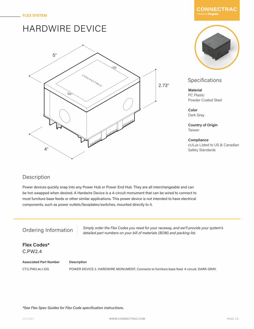
HARDWIRE DEVICE
Specifications
Description
Power devices quickly snap into any Power Hub or Power End Hub. They are all interchangeable and can be hot-swapped when desired. A Hardwire Device is a 4-circuit monument that can be wired to connect to most furniture base feeds or other similar applications. This power device is not intended to have electrical components, such as power outlets/faceplates/switches, mounted directly to it.
Ordering Information
Associated Part Number Description
Simply order the Flex Codes you need for your raceway, and we’ll provide your system’s detailed part numbers on your bill of materials (BOM) and packing list.
C.PW2.4
CT.C.PW2.4c.1-DG POWER DEVICE 2. HARDWIRE MONUMENT. Connects to furniture base feed. 4-circuit. DARK GRAY.
*See Flex Spec Guides for Flex Code specification instructions.
Flex Codes*
MaterialPC PlasticPowder Coated Steel
ColorDark Gray
Country of OriginTaiwan
CompliancecULus Listed to US & Canadian Safety Standards4”
5”
2.73”
WWW.CONNECTRAC.COM PAGE 23
FLEX SYSTEM
WWW.CONNECTRAC.COM02112021 PAGE 24
FLEX SYSTEM
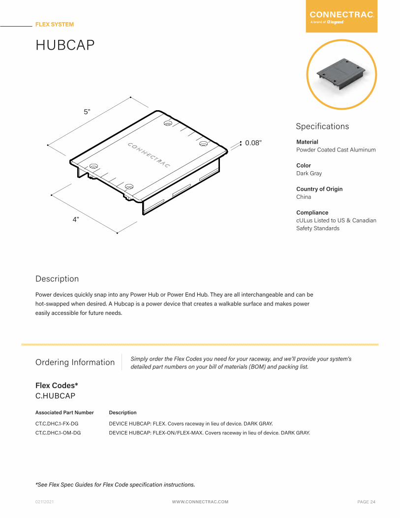
HUBCAP
Specifications
Description
Power devices quickly snap into any Power Hub or Power End Hub. They are all interchangeable and can be hot-swapped when desired. A Hubcap is a power device that creates a walkable surface and makes power easily accessible for future needs.
Ordering Information
Associated Part Number Description
Simply order the Flex Codes you need for your raceway, and we’ll provide your system’s detailed part numbers on your bill of materials (BOM) and packing list.
C.HUBCAP
CT.C.DHC.1-FX-DG
CT.C.DHC.1-OM-DG
DEVICE HUBCAP: FLEX. Covers raceway in lieu of device. DARK GRAY.
DEVICE HUBCAP: FLEX-ON/FLEX-MAX. Covers raceway in lieu of device. DARK GRAY.
*See Flex Spec Guides for Flex Code specification instructions.
Flex Codes*
MaterialPowder Coated Cast Aluminum
ColorDark Gray
Country of OriginChina
CompliancecULus Listed to US & Canadian Safety Standards
4”
5”
0.08”
WWW.CONNECTRAC.COM PAGE 24
FLEX SYSTEM
WWW.CONNECTRAC.COM02112021 PAGE 25
FLEX SYSTEM
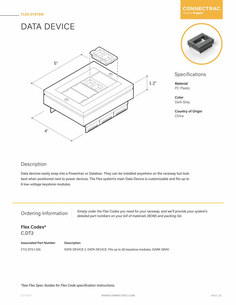
DATA DEVICE
Specifications
Description
Data devices easily snap into a Powertrac or Datatrac. They can be installed anywhere on the raceway but look best when positioned next to power devices. The Flex system’s main Data Device is customizable and fits up to 8 low-voltage keystone modules.
Ordering Information
Associated Part Number Description
Simply order the Flex Codes you need for your raceway, and we’ll provide your system’s detailed part numbers on your bill of materials (BOM) and packing list.
C.DT2
CT.C.DT2.1-DG DATA DEVICE 2. DATA DEVICE. Fits up to (8) keystone modules. DARK GRAY.
*See Flex Spec Guides for Flex Code specification instructions.
Flex Codes*
MaterialPC Plastic
ColorDark Gray
Country of OriginChina
4”
5”
1.2”
WWW.CONNECTRAC.COM PAGE 25
FLEX SYSTEM

WWW.CONNECTRAC.COM02112021 PAGE 26
FLEX SYSTEM
TRANSITION RAMPS
Specifications
Description
Transition Ramps sit adjacent to a Powertrac or Datatrac, and help to transition the flooring material from the raceway to the surrounding flooring.
Ordering Information
Associated Part Number Description
Simply order the Flex Codes you need for your raceway, and we’ll provide your system’s detailed part numbers on your bill of materials (BOM) and packing list.
N/A - Contact us to order
CT.02-FM-SRS.1-03
CT.02-FM-SRS.1-06
3’ SIDE RAMP SET: FLEX/FLEX-MAX. (2) 3’ sets. [6 linear feet/3’ per side].
6’ SIDE RAMP SET: FLEX/FLEX-MAX. (2) 6’ sets. [12 linear feet/6’ per side].
Flex Codes*
MaterialMoisture-resistant MDF
Country of OriginUnited States
WWW.CONNECTRAC.COM PAGE 26
FLEX SYSTEM

WWW.CONNECTRAC.COM02112021 PAGE 27
FLEX SYSTEM
END RAMPS
Specifications
Description
End Ramps sit at the end of a Powertrac or Datatrac, and help to transition the flooring material from the raceway to the surrounding flooring.
Ordering Information
Associated Part Number Description
Simply order the Flex Codes you need for your raceway, and we’ll provide your system’s detailed part numbers on your bill of materials (BOM) and packing list.
N/A - Contact us to order
CT.02-FM-ER.1
CT.02-FM-ERF.1
END RAMP: FLEX/FLEX-MAX end-of-raceway transition ramps.
END RAMP FILLER: FLEX/FLEX-MAX raceway filler piece for ganging raceways.
Flex Codes*
MaterialPC Plastic
Country of OriginChina
CompliancecULus Listed to US & Canadian Safety Standards
4”
15”
WWW.CONNECTRAC.COM PAGE 27
FLEX SYSTEM

WWW.CONNECTRAC.COM02112021 PAGE 28
FLEX SYSTEM
TOP COVER
Measurements for both install options shown:
B.ON seriesB.FX series(for installation under carpet tile) (for installation on top of any flooring surface)
Specifications
Description
Top Covers are included with every Flex raceway order. They conceal and protect Powertracs, Powertrac Extenders, and Datatracs. Top Covers for the Flex under-carpet system are hidden under the carpet tile. Top Covers for the Flex on-floor system are visible on top of the flooring surface and are available in a standard Silver finish or an optional Dark Gray finish for an extra charge.
0.59” 0.74”
4” 4”
Ordering Information
Associated Part Number Description
Simply order the Flex Codes you need for your raceway, and we’ll provide your system’s detailed part numbers on your bill of materials (BOM) and packing list.
N/A - Contact us to order
CT.01-TC-FX.1-03
CT.01-TC-OM.1-03-DG
CT.01-TC-OM.1-03-SV
CT.01-TC-OM.1-06-DG
CT.01-TC-OM.1-06-SV
3’ TOP COVER: FLEX/EXPRESS.
3’ TOP COVER: FLEX-ON/FLEX-MAX. DARK GRAY.
3’ TOP COVER: FLEX-ON/FLEX-MAX. SILVER.
6’ TOP COVER: FLEX-ON/FLEX-MAX. DARK GRAY.
6’ TOP COVER: FLEX-ON/FLEX-MAX. SILVER.
*See Flex Spec Guides for Flex Code specification instructions.
Flex Codes*
MaterialAluminum
Color (B.ON series only)Dark GraySilver
Country of OriginUnited States
4”
L
WWW.CONNECTRAC.COM PAGE 28
FLEX SYSTEM
WWW.CONNECTRAC.COM02112021 PAGE 29
FLEX SYSTEM
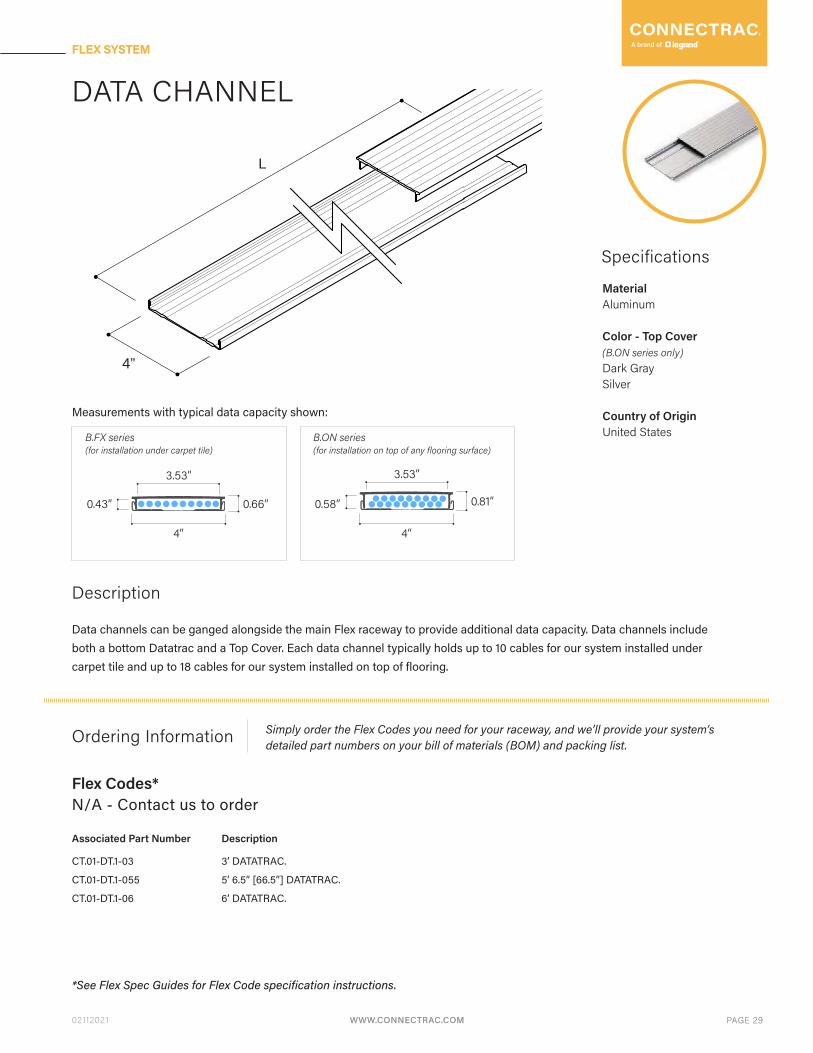
DATA CHANNEL
Measurements with typical data capacity shown:
B.ON seriesB.FX series(for installation under carpet tile) (for installation on top of any flooring surface)
Specifications
Description
Data channels can be ganged alongside the main Flex raceway to provide additional data capacity. Data channels include both a bottom Datatrac and a Top Cover. Each data channel typically holds up to 10 cables for our system installed under carpet tile and up to 18 cables for our system installed on top of flooring.
0.66” 0.81”
4” 4”
0.43” 0.58”
Ordering Information
Associated Part Number Description
Simply order the Flex Codes you need for your raceway, and we’ll provide your system’s detailed part numbers on your bill of materials (BOM) and packing list.
N/A - Contact us to order
CT.01-DT.1-03
CT.01-DT.1-055
CT.01-DT.1-06
3’ DATATRAC.
5’ 6.5” [66.5”] DATATRAC.
6’ DATATRAC.
*See Flex Spec Guides for Flex Code specification instructions.
Flex Codes*
MaterialAluminum
Color - Top Cover(B.ON series only)Dark GraySilver
Country of OriginUnited States
4”
L
3.53” 3.53”
WWW.CONNECTRAC.COM PAGE 29
FLEX SYSTEM

WWW.CONNECTRAC.COM02112021 PAGE 30
FLEX SYSTEM
WIREWAY CAPACITY & DIMENSIONS
FLEX SYSTEM TECHNICAL GUIDE
Powertrac
Data Channel
Powertracs are pre-wired raceway segments available in five nominal lengths (2’, 3’, 4’, 5’, 6’) that come complete with Top Covers and Transition Ramps. Each Powertrac has modular connectors on each end that easily snap into an Entrance Fitting, Powertrac Extender, Powertrac Corner, Power Hub, or Power End Hub to build your Flex raceway.
Data channels can be ganged alongside the main Flex raceway to provide additional data capacity. Data channels include both a bottom Datatrac and a Top Cover. Each data channel typically holds up to 10 cables for our system installed under carpet tile and up to 18 cables for our system installed on top of flooring.
(Measurements with Top Covers installed and typical data capacity shown.)
B.ON series
B.ON series
B.FX series
FOR INSTALLATION UNDER CARPET TILE
FOR INSTALLATION UNDER CARPET TILE
FOR INSTALLATION ON TOP OF ANY FLOORING SURFACE
FOR INSTALLATION ON TOP OF ANY FLOORING SURFACE
B.FX series
(up to 4 cables)
(up to 10 cables)
(up to 6 cables)
(up to 18 cables)
0.43”
0.43”
0.58”
0.58”
0.6”
3.53”
0.6”
3.53”
WWW.CONNECTRAC.COM PAGE 30
FLEX SYSTEM