Embed Size (px)
Citation preview
Valvola a farfallaButterfly valveVanne à papillonAbsperrklappe
FK PVC-C

FK PVC-C
144
I dati del presente prospetto sono forniti in buona fede. La FIP non si assume alcu-na responsabilità su quei dati non diret-tamente derivati da norme internazionali. La FIP si riserva di apportarvi qualsiasi modifica.
The data given in this leaflet are offered in good faith. No liability can be accepted concerning technical data that are not directly covered by recognized interna-tional standards. FIP reserves the right to carry out any modification to the products shown in this Ieaflet.
Les données contenues dans cette brochure sont fournies en bonne foi. FIP n’assume aucune responsabilité pour les données qui ne dérivent pas directement des normes internationa-les. FIP garde le droit d’apporter toute modification aux produits présentés dans cette brochure.
Alle Daten dieser Druckschrift wurden nach bestem Wissen angegeben, jedoch besteht keine Verbindlichkeit, sofern sie nicht direkt internationalen Normen entnommen wurden. Die Än-derung von Maßen oder Ausführungen bleibt FIP vorbehalten.
FK PVC-C
145
• Valvola di intercettazione e regolazione• Gamma dimensionale DN 40 ÷ 200 mm, serie DIN 3202 K2 e
ISO 5752 Medium serie 25. DN 250 ÷ 300 mm, serie DIN 3202 K3 e
ISO 5752 Long serie 16.• Resistenza a pressioni di esercizio
fino a 16 bar a 20°C• Materiale del corpo: PP-GR resistente ai raggi UV• Lente intercambiabile in materiali
termoplastici: PVC, PP-H, PVCC, ABS, PVDF
• Sistema di foratura ad asole ovali per l’accoppiamento secondo numerosi standards internazionali; lunette in ABS in dotazione per facilitare l’autocentraggio di flange e bulloni fino al DN 200; DN 250 e 300 fornite con foratura secondo i diversi standard
• Versione manuale a leverismo con maniglia ergonomica in PVC dotata di dispositivo di blocco, sblocco, manovra rapida e
regolazione graduata• Possibilità di installare riduttore
manuale o attuatori pneumatici e/o elettrici mediante l’applicazio-ne di flangette in PP-GR a foratura standard ISO 5211 F05, F07, F10, fino al DN 200, foratura F10, F12, F14 senza flangette per DN 250 ÷ 300
• Versione speciale anulare lug PN 10 a foratura completa DIN 2501, ANSI 150 con inserti in acciaio inossidabile AISI 316 affogati a caldo.
• Tenuta primaria intercambiabile con manicotto in elastomero EPDM, FPM, NBR
• Possibilità di installazione anche come valvola di fine linea o di sca-rico di fondo o rapido da serbatoio
• Per maggiori informazioni visitare il sito:
www.fipnet.it
• Used for fast control and ON/OFF operations• Size range: from DN 40 up to DN
200 mm, series DIN 3202 K2 and ISO 5752 Medium series 25, DN 250 ÷ 300 mm, serie DIN 3202 K3 and ISO 5752 long series 16
• Working pressure up to 16 bar at 20°C
• Body material: GR-PP, resistant to UV rays
• Interchangeable disc in: PVC, PP-H, CPVC, ABS, PVDF
• Full flanged body with oval holes to fit with flanges in different stan-dards; equipped with ABS inserts to centre flanges and bolts up to DN 200; DN 250 and 300 drilling on request according to different standards
• Hand operated version with ergonomic PVC hand lever, provided with locking device,
quick manoeuvring, flow throttling (10 stops to position
the disc every 10°)• Possibility to install gear box and
actuators by means of a GR-PP upper flange with standard drilling (ISO 5211 F05, F07, F10), up to DN 200, drilling F10, F12, F14 without upper flange for DN 250 ÷ 300
• Special full drilled lug version PN 10 with captive stainless steel AISI 316 inserts (DIN 2501 or ANSI 150)
• Interchangeable primary liner in elastomer EPDM, FPM, or NBR.
• Possible mounting of valve as end valve, or quick discharge from tanks
• For more information please visit our website:
www.fipnet.it
• Vanne d’arrêt et de régulation• Gamme dimensionnelle de DN 40
à DN 200 mm, série DIN 3202 K2 et ISO 5752 Medium série 25. DN 250 ÷ 300 mm, série DIN 3202 K3 et ISO 5752 long série 16
• Pression de service jusqu’à 16 bar à 20°C
• Matériau corps: PP-GR résistant aux rayons UV
• Disque interchangeable en ma-tériaux thermoplastiques: PVC, PP-H, PVCC, ABS, PVDF
• Système de perçage par trous ovales permettant l’accouplement selon plusieurs standards interna-tionaux; entretoises en ABS en do-tation pour faciliter l’auto-centrage de brides et boulons jusq’au DN 200; DN 250 et 300 perçage par trous selon plusieurs standards in-ternationaux sur demande
• Version manuelle à lévier avec poignée ergonomique en PVC, pourvue d’un dispositif de blocage
• Possibilité de montage d’un réducteur manuel ou d’actionneurs grace à l’application d’une bride standard en PP-GR (perçage ISO 5211 F05, F07, F10), jusq’au DN 200, perçage F10, F12, F14 sans bride pour DN 250 et 300
• Version spéciale annulaire lug PN 10 à perçage complet DIN 2501, ANSI 150 avec inserts en acier inoxydable AISI 316 moulés
• Manchette interchangeable en élastomère EPDM, FPM, NBR
• Possibilité de montage en fin de ligne, ou sur réservoir
• Pour avoir d’autres informations, visiter le site:
www.fipnet.it
• Geeignet für Drossel- und Absperrfunktionen
• Abmessungen von DN 40 bis DN 200 mm, entsprechend DIN 3202 K2 und ISO 5752 Baulänge mittel, Serie 25. DN 250 ÷300 mm, serie DIN 3202 K3 e ISO 5752 Long serie 16
• Höchstzulässiger Betriebsdruck 16 bar bei 20° C
• Material des Klappenkörpers: GR - PP, beständig gegenüber UV - Strahlung
• Klappenscheibe aus PVC-U, PVC-C, PP - H, ABS und PVDF, austauschbar
• Voll flanschbarer Klappenkörper mit ovalen Schraubenlöchern für Flansche nach verschiede-nen Normen; ausgerüstet mit Einsätzen aus ABS zum Zentrieren der Schrauben und Flansche bis DN 200; DN 250 und DN 300 verfügbar mit Schraublöcher nach verschiedenen Normen gemaß Anfrage
• Manuelle Ausführung mit ergonomischem, in 10 Positionen
(10° Stufen) rastbarem Handhebel, für eine schnelle Durchflußregulierung
• Adapterflansch, für eine einfache Montage von Handgetriebe oder Antrieb, mit den Anschlußmaßen F 05, F 07, F10 nach ISO 5211 auf Anfrage bis DN 200; Anschluß-maßen F10, F12, F14 ohne Adapter-flansch für DN 250 ÷ 300
• Spezielle Ausführung als Endabsperrklappe (PN 10) voll verschraubt, mit integrierten Gewindeeinsätzen aus rostfreiem Stahl (AISI 316), Anschlußmaße nach DIN 2501 oder ANSI 150
• Der Klappenkörper ist nicht mediumberührt. Die Auskleidung
ist mit der Dichtung kombiniert und auswechselbar
• Die Absperrklappe kann auch als Schnellentnahmearmatur, z.B. an Tanks eingesetzt werden.
• Für weitere Details schauen Sie auf unsere Website:
www.fipnet.it
Valvola a farfalla Butterfly valve Vanne à papillon Absperrklappe
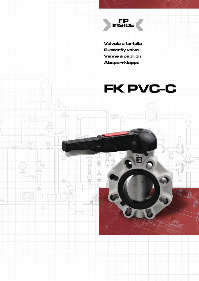
PNEUMATIC ACTUATOR GEAR BOX ELECTRIC ACTUATOR HAND LEVER
FK PVC-C
146
Legenda
d diametro nominale esterno del tubo in mm
DN diametro nominale interno in mm
PN pressione nominale in bar (pressione max di esercizio a 20°C in acqua)
g peso in grammi
U numero dei fori
SDR standard dimension ratio = d/s
PVC-U cloruro di polivinile rigido
PP-H polipropilene omopolimero
PP-GR polipropilene rinforzato fibre di vetro
PVC-C cloruro di polivinile surclorato
ABS acrilonitrile butadiene stirene
PVDF polifluoruro di vinilidene
HIPVC cloruro di polivinile rigido
EPDM elastomero etilene propilene
FPM (FKM) fluoroelastomero
NBR elastomero butadiene acrilonitrile
PTFE politetrafluoroetilene
PE polietilene
d nominal outside diame-ter of the pipe in mm
DN nominal internal diameter in mm
PN nominal pressure in bar (max. working pressure at 20°C - water)
g weight in grams
U number of holes
SDR standard dimension ratio = d/s
PVC-U unplasticized polyvinyl chloride
PP-H polypropylene homopolymer
PP-GR polypropylene fiber glass reinforced
PVC-C chlorinated polyvinyl chloride
ABS acrylonitrile-butadiene- styrene
PVDF polyvinylidene fluoride
HIPVC unplasticized polyvinyl chloride
EPDM ethylene propylene rubber
FPM (FKM) vinylidene fluoride rubber
NBR butadiene-acrylonitrile rubber
PTFE polytetrafluoroethylene
PE polyethylene
d diamètre extérieur nominal du tube en mm
DN diamètre intérieur nomi-nal du tube en mm PN
PN pression nominale en bar (pression de service max à 20°C- eau)
g poids en grammes
U nombre de trous
SDR standard dimension ratio = d/s
PVC-U polychlorure de vinyle non plastifié
PP-H polypropylène homopolymère
PP-GR polypropylène renforcé fibre de verre
PVC-C polychlorure de vinyle surchloré
ABS acrylonitrile butadiène styrène
PVDF polyfluorure de vinylidène
HIPVC polychlorure de vinyle non plastifié
EPDM élastomère ethylène propylène
FPM (FKM) fluorélastomère de vinylidène
NBR caoutchouc butadiène acrylonitrile
PTFE polytétrafluoroéthylène
PE polyethylène
d Rohraußendurchmesser in mm
DN Rohrnennweite in mm
PN Nenndruck; höchstzu-lässiger Betriebsdruck in bar, bei 20° C Wasser
g Gewicht in Gramm
U Anzahl der Schraubenlöcher
SDR Standard Dimension Ratio = d/s
PVC-U Polyvinylchlorid hart
PP-H Polypropylen Homopolimerisat
PP-GR Polypropylen glasfaserverstärkt
PVC-C Polyvinylchlorid nachchloriert
ABS Acrylnitril-Butadien- Styrol
PVDF Polyvinylidenfluorid
HIPVC Polyvinylchlorid hart
EPDM Ethylenpropylen- dienelastomer
FPM (FKM) Fluorelastomer
NBR Nitrilelastomer
PTFE Polytetraflourethylen
PE Polyethylen
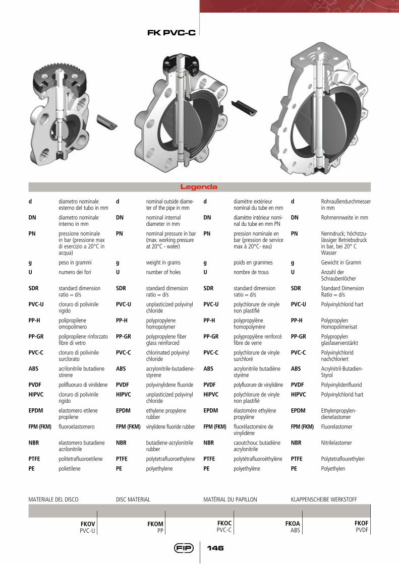
FKOVPVC-U
FKOCPVC-C
FKOAABS
FKOFPVDF
FKOMPP
MATERIALE DEL DISCO DISC MATERIAL MATÉRIAL DU PAPILLON KLAPPENSCHEIBE WERKSTOFF
FK PVC-C
147
Dati Tecnici
Technical Data
Données Techniques
Technische Daten
1
3
5
1
2
2
3
4
values certified according to EN 1267
651700
401000
501285
DNkv100
803550
1005900
1259850
20030500
25053200
30081600
15018700
325
300
275
250
225
200
175
150
125
100
75
50
25
0
Nm d DN
63 50
90 80
50 40
75 65
110 100
140 125
160 150
225 200
280 250
315 300
mom
ento
di m
anov
ra -
torq
ue -
coup
le
de m
anoe
uvre
- Be
tätig
ungs
mom
ente
DN 40
DN 50
DN 65
DN 80
DN 10
0DN
125
1000 l/min10000 10000010010
DN 15
0DN
200
DN 25
0DN
300
bar
1
0,1
0,01
0,001perd
ita d
i car
ico -
pres
sure
lost
- pe
rte d
e ch
arge
- Dr
uckv
erlu
stportata - flow rate- débit - Durchflußmenge
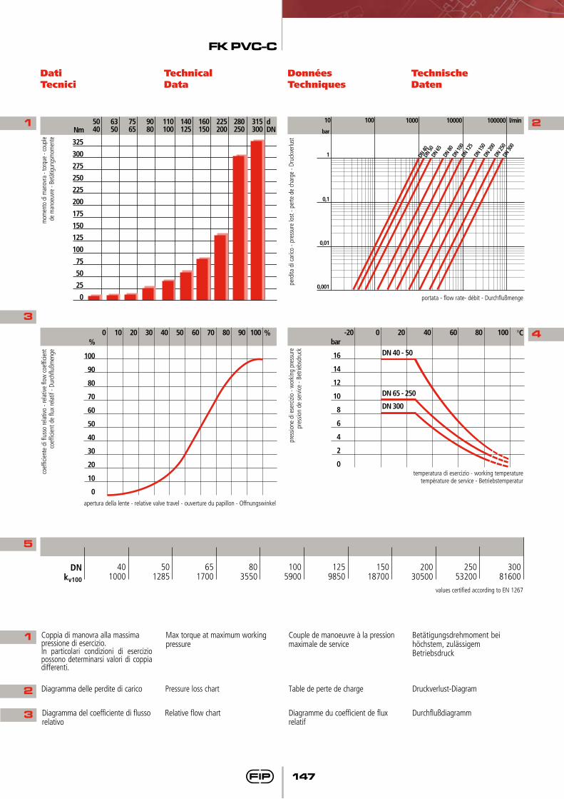
Coppia di manovra alla massima pressione di esercizio.In particolari condizioni di esercizio possono determinarsi valori di coppia differenti.
Max torque at maximum working pressure
Couple de manoeuvre à la pression maximale de service
Betätigungsdrehmoment bei höchstem, zulässigem Betriebsdruck
Diagramma delle perdite di carico Pressure loss chart Table de perte de charge Druckverlust-Diagram
Diagramma del coefficiente di flusso relativo
Relative flow chart Diagramme du coefficient de flux relatif
Durchflußdiagramm
bar
16
14
12
10
8
6
4
2
0
-20 0 20 40 °C60 10080
DN 40 - 50
DN 65 - 250
DN 300
pres
sione
di e
serc
izio
- wor
king
pre
ssur
epr
essio
n de
ser
vice
- Bet
riebs
druc
k
temperatura di esercizio - working temperaturetempérature de service - Betriebstemperatur
%
100
90
80
70
60
50
40
30
20
10
0
0 10 20 30 %40 10050 60 70 80 90
apertura della lente - relative valve travel - ouverture du papillon - Offnungswinkel
coef
ficie
nte
di fl
usso
rela
tivo
- rel
ative
flow
coe
fficie
ntco
effic
ient
de
flux
rela
tif -
Durc
hflu
ßmen
ge
FK PVC-C
148
Dimensioni Dimensions Dimensions Dimensionen
Le dimensioni di ingombro della valvola a farfalla FK sono in accordo con la norma ISO 5752 (DN 40÷200 Medium Serie 25, DN 250÷300 Long Serie 16) e DIN 3202 (DN 65÷200 K2, DN 250÷300 K3).
La foratura del corpo permette l’accoppiamento con dimensioni di foratura secondo le seguenti norme internazionali: - DIN 2501, ISO DIS 9624, UNI 2223- BS 10 table D/E (DN 250 E)- ASA ANSI B16,5 class 150- JIS 2212 (K10 ad esclusione DN 200/DN 300), JIS 2212 (K5 ad esclusione DN 50)
Les dimensions d’encombrement de la vanne à papillon FK sont conformes aux normes ISO 5752 (DN 40÷200 Medium Serie 25, DN 250÷300 Long Serie 16) e DIN 3202 (DN 65÷200 K2, DN 250÷300 K3).
Le perçage du corps permet l’accouplement suivant les nor mes internationales:- DIN 2501, ISO DIS 9624, UNI 2223- BS 10 table D/E- ASA B16,5 class 150- JIS 2212 (K10 sauf DN 200/DN
300), JIS 2212 (K5 sauf DN 50)
Die Baulängen der FK - Apsperrklappen entsprechen den folgenden Normen: ISO 5752 (DN 40÷200 Medium Serie 25, DN 250÷300 Long Serie 16) e DIN 3202 (DN 65÷200 K2, DN 250÷300 K3).
Ovale Schraubenlöcher im Klappengehäuse ermöglichen den Einbau zwischen Flansche mit Anschlußmaßen nach folgenden Normen:- DIN 2501, ISO DIS 9624, UNI 2223- BS 10 table D/E- ASA B 16,5 Class 150- JIS 2212 (K 10 mit Ausnahme DN 200/ DN 300), JIS 2212 (K5 mit Ausnahme DN 50)
The overall dimensions of the FK butterfly valve comply with the following standards: ISO 5752 (DN 40÷200 Medium Serie 25, DN 250÷300 Long Serie 16) e DIN 3202 (DN 65÷200 K2, DN 250÷300 K3).
Oval holes in the valve body allow connections to flanges with different drillings:- DIN 2501, ISO DIS 9624, UNI 2223- BS 10 table D/E- ASA B16,5 class 150- JIS 2212 (K10 except for DN 200/DN 300), JIS 2212 (K5 except for DN 50)
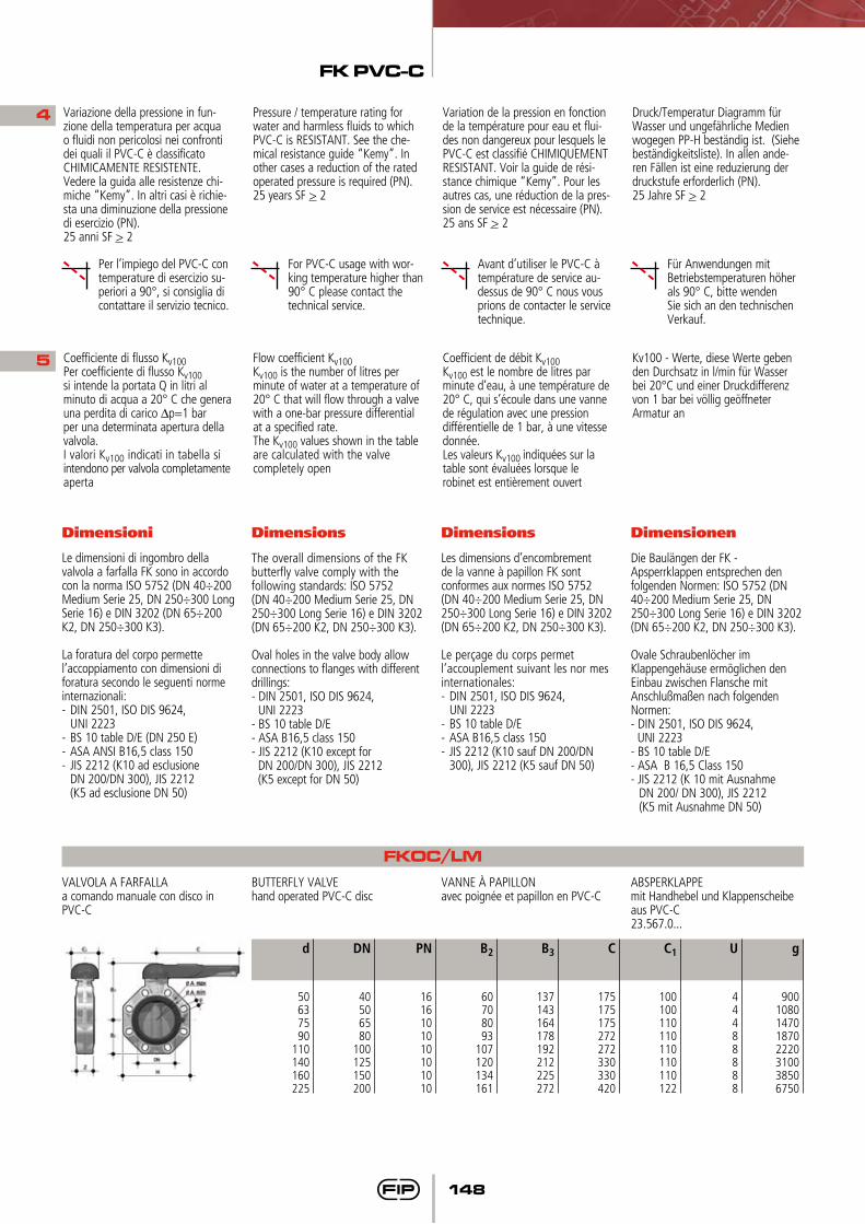
FKOC/LMVALVOLA A FARFALLAa comando manuale con disco in PVC-C
BUTTERFLY VALVEhand operated PVC-C disc
VANNE à PAPILLONavec poignée et papillon en PVC-C
ABSPERKLAPPEmit Handhebel und Klappenscheibe aus PVC-C23.567.0...
4
5 Coefficiente di flusso Kv100Per coefficiente di flusso Kv100si intende la portata Q in litri al minuto di acqua a 20° C che genera una perdita di carico ∆p=1 bar per una determinata apertura della valvola.I valori Kv100 indicati in tabella si intendono per valvola completamente aperta
Flow coefficient Kv100 Kv100 is the number of litres per minute of water at a temperature of 20° C that will flow through a valve with a one-bar pressure differential at a specified rate. The Kv100 values shown in the table are calculated with the valve completely open
Coefficient de débit Kv100Kv100 est le nombre de litres par minute d’eau, à une température de 20° C, qui s’écoule dans une vanne de régulation avec une pression différentielle de 1 bar, à une vitesse donnée.Les valeurs Kv100 indiquées sur la table sont évaluées lorsque le robinet est entièrement ouvert
Kv100 - Werte, diese Werte geben den Durchsatz in l/min für Wasser bei 20°C und einer Druckdifferenz von 1 bar bei völlig geöffneter Armatur an
d
50637590
110140160225
B2
60708093
107120134161
B3
137143164178192212225272
C
175175175272272330330420
PN
1616101010101010
DN
40506580
100125150200
C1
100100110110110110110122
g
9001080147018702220310038506750
U
44488888
Variazione della pressione in fun-zione della temperatura per acqua o fluidi non pericolosi nei confronti dei quali il PVC-C è classificato CHIMICAMENTE RESISTENTE. Vedere la guida alle resistenze chi-miche “Kemy”. In altri casi è richie-sta una diminuzione della pressione di esercizio (PN).25 anni SF > 2
Per l’impiego del PVC-C con temperature di esercizio su-periori a 90°, si consiglia di contattare il servizio tecnico.
For PVC-C usage with wor-king temperature higher than 90° C please contact the technical service.
Avant d’utiliser le PVC-C à température de service au-dessus de 90° C nous vous prions de contacter le service technique.
Für Anwendungen mit Betriebstemperaturen höher als 90° C, bitte wenden Sie sich an den technischen Verkauf.
Pressure / temperature rating for water and harmless fluids to which PVC-C is RESISTANT. See the che-mical resistance guide “Kemy”. In other cases a reduction of the rated operated pressure is required (PN). 25 years SF > 2
Variation de la pression en fonction de la température pour eau et flui-des non dangereux pour lesquels le PVC-C est classifié CHIMIQUEMENT RESISTANT. Voir la guide de rési-stance chimique “Kemy”. Pour les autres cas, une réduction de la pres-sion de service est nécessaire (PN). 25 ans SF > 2
Druck/Temperatur Diagramm für Wasser und ungefährliche Medien wogegen PP-H beständig ist. (Siehe beständigkeitsliste). In allen ande-ren Fällen ist eine reduzierung der druckstufe erforderlich (PN).25 Jahre SF > 2
FK PVC-C
149
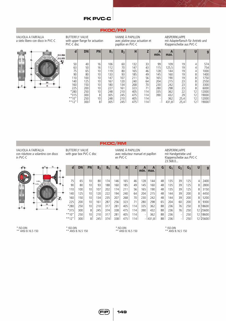
FKOC/FMVALVOLA A FARFALLAa stelo libero con disco in PVC-C
BUTTERFLY VALVEwith upper flange for actuation PVC-C disc
VANNE à PAPILLONavec platine pour actuation et papillon en PVC-C
ABSPERRKLAPPEmit Adapterflansch für Antrieb und Klappenscheibe aus PVC-C
FKOC/RMVALVOLA A FARFALLAcon riduttore a volantino con disco in PVC-C
BUTTERFLY VALVEwith gear box PVC-C disc
VANNE à PAPILLONavec reducteur manuel et papillon en PVC-C
ABSPERRKLAPPEmit Handgetriebe und Klappenscheibe aus PVC-C23.568.0...
d
50637590
110140160225
*280*315
**10”**12”
B1
106112119133147167180227248305248305
B2
60708093
107120134161210245210245
PN
1616101010101010108
108
DN
40506580
100125150200250300250300
H
132147165185211240268323405475405475
Z
3343464956647071
114114114114
Amin.
99115128145165204230280335390
--
Amax.
109125,5
144160190215242298362432362
431,8
f
19191919192323232229
25,425,4
g
574754
100014001750255033006000
12000190001200019000
U
44488888
12121212
* ISO-DIN** ANSI B.16.5 150
* ISO-DIN** ANSI B.16.5 150
* ISO-DIN** ANSI B.16.5 150
* ISO-DIN** ANSI B.16.5 150
d
7590
110140160225
*280*315
**10”**12”
B2
8093
107120134161210245210245
B5
174188202222235287317374317374
B6
146160174194207256281338281338
H
165185211240268323405475405475
Z
464956647071
114114114114
Amin.
128145165204230280335390
--
Amax.
144160190215242298362432362
431,8
G
48484848486588888888
G1
135135135144144204236236236236
PN
10101010101010
810
8
DN
6580
100125150200250300250300
G2
3939393939607676
--
G3
125125125200200200250250250250
g
240028003150445052009300
18600256001860025600
U
4888888
121212
FK PVC-C
150
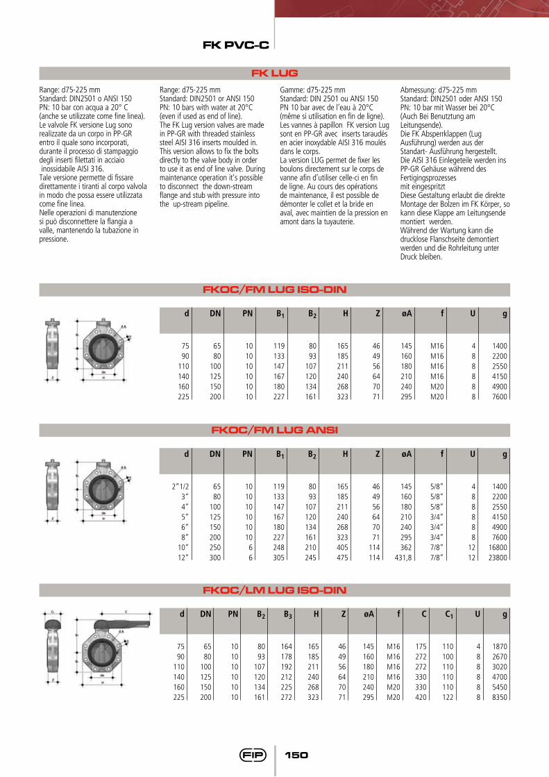
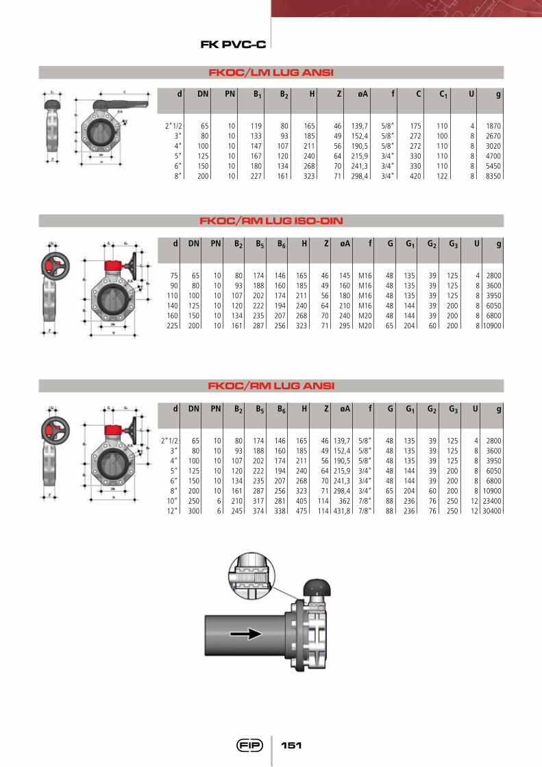
FK LUGRange: d75-225 mmStandard: DIN2501 o ANSI 150PN: 10 bar con acqua a 20° C (anche se utilizzate come fine linea).Le valvole FK versione Lug sono realizzate da un corpo in PP-GR entro il quale sono incorporati, durante il processo di stampaggio degli inserti filettati in acciaio inossidabile AISI 316.Tale versione permette di fissare direttamente i tiranti al corpo valvola in modo che possa essere utilizzata come fine linea.Nelle operazioni di manutenzione si può disconnettere la flangia a valle, mantenendo la tubazione in pressione.
Range: d75-225 mmStandard: DIN2501 or ANSI 150PN: 10 bars with water at 20°C (even if used as end of line).The FK Lug version valves are made in PP-GR with threaded stainless steel AISI 316 inserts moulded in.This version allows to fix the bolts directly to the valve body in order to use it as end of line valve. During maintenance operation it’s possible to disconnect the down-stream flange and stub with pressure into the up-stream pipeline.
Gamme: d75-225 mmStandard: DIN 2501 ou ANSI 150PN 10 bar avec de l’eau à 20°C (même si utilisation en fin de ligne).Les vannes à papillon FK version Lug sont en PP-GR avec inserts taraudés en acier inoxydable AISI 316 moulés dans le corps. La version LUG permet de fixer les boulons directement sur le corps de vanne afin d’utiliser celle-ci en fin de ligne. Au cours des opérations de maintenance, il est possible de démonter le collet et la bride en aval, avec maintien de la pression en amont dans la tuyauterie.
Abmessung: d75-225 mmStandard: DIN2501 oder ANSI 150PN: 10 bar mit Wasser bei 20°C (Auch Bei Benutztung am Leitungsende).Die FK Absperrklappen (Lug Ausführung) werden aus der Standart- Ausführung hergestellt.Die AISI 316 Einlegeteile werden ins PP-GR Gehäuse während des Fertigingsprozessesmit eingespritztDiese Gestaltung erlaubt die direkte Montage der Bolzen im FK Körper, so kann diese Klappe am Leitungsende montiert werden.Während der Wartung kann die drucklose Flanschseite demontiert werden und die Rohrleitung unter Druck bleiben.
FKOC/FM LUG ISO-DIN
FKOC/FM LUG ANSI
d
7590
110140160225
B1
119133147167180227
B2
8093
107120134161
PN
101010101010
DN
6580
100125150200
H
165185211240268323
Z
464956647071
øA
145160180210240295
f
M16M16M16M16M20M20
g
140022002550415049007600
U
488888
d
2”1/23”4”5”6”8”
10”12”
B1
119133147167180227248305
B2
8093
107120134161210245
PN
10101010101066
DN
6580
100125150200250300
H
165185211240268323405475
Z
464956647071
114114
øA
145160180210240295362
431,8
f
5/8”5/8”5/8”3/4”3/4”3/4”7/8”7/8”
g
140022002550415049007600
1680023800
U
488888
1212
FKOC/LM LUG ISO-DIN
d
7590
110140160225
B2
8093
107120134161
B3
164178192212225272
C
175272272330330420
PN
101010101010
DN
6580
100125150200
C1
110100110110110122
g
187026703020470054508350
U
488888
H
165185211240268323
Z
464956647071
øA
145160180210240295
f
M16M16M16M16M20M20
FK PVC-C
151
FKOC/RM LUG ISO-DIN
FKOC/RM LUG ANSI
FKOC/LM LUG ANSI
d
2”1/23”4”5”6”8”
B1
119133147167180227
B2
8093
107120134161
PN
101010101010
DN
6580
100125150200
H
165185211240268323
Z
464956647071
øA
139,7152,4190,5215,9241,3298,4
f
5/8”5/8”5/8”3/4”3/4”3/4”
g
187026703020470054508350
U
488888
d
7590
110140160225
d
2”1/23”4”5”6”8”
10”12”
B2
8093
107120134161
B2
8093
107120134161210245
B5
174188202222235287
B5
174188202222235287317374
B6
146160174194207256
B6
146160174194207256281338
G
484848484865
G
4848484848658888
G1
135135135144144204
G1
135135135144144204236236
PN
101010101010
PN
101010101010
66
DN
6580
100125150200
DN
6580
100125150200250300
G2
393939393960
G2
3939393939607676
G3
125125125200200200
G3
125125125200200200250250
g
28003600395060506800
10900
g
28003600395060506800
109002340030400
U
488888
U
488888
1212
H
165185211240268323
H
165185211240268323405475
Z
464956647071
Z
464956647071
114114
øA
145160180210240295
øA
139,7152,4190,5215,9241,3298,4
362431,8
f
M16M16M16M16M20M20
f
5/8”5/8”5/8”3/4”3/4”3/4”7/8”7/8”
C
175272272330330420
C1
110100110110110122
FK PVC-C
152
Accessori Accessories Accessoires Zubehör
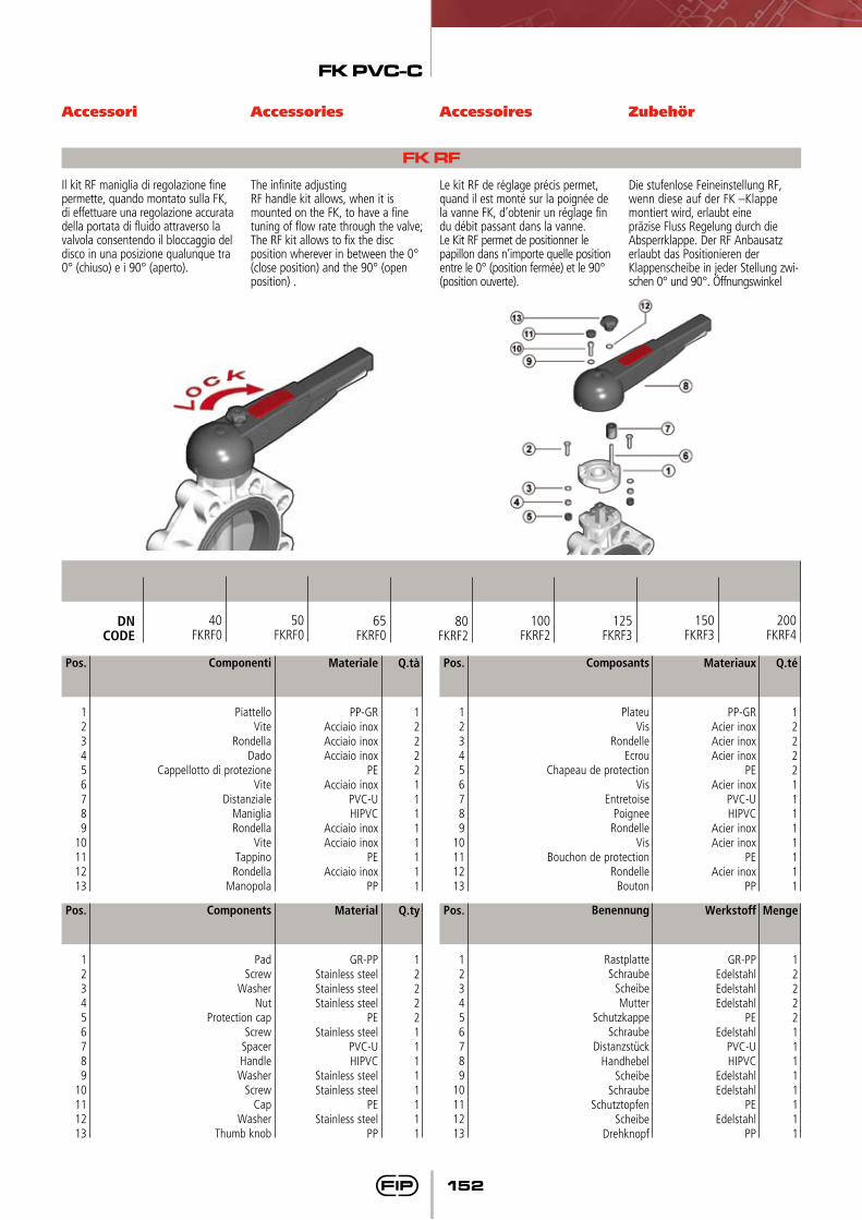
Il kit RF maniglia di regolazione fine permette, quando montato sulla FK, di effettuare una regolazione accurata della portata di fluido attraverso la valvola consentendo il bloccaggio del disco in una posizione qualunque tra 0° (chiuso) e i 90° (aperto).
The infinite adjusting RF handle kit allows, when it is mounted on the FK, to have a fine tuning of flow rate through the valve; The RF kit allows to fix the disc position wherever in between the 0° (close position) and the 90° (open position) .
Le kit RF de réglage précis permet, quand il est monté sur la poignée de la vanne FK, d’obtenir un réglage fin du débit passant dans la vanne. Le Kit RF permet de positionner le papillon dans n’importe quelle position entre le 0° (position fermée) et le 90° (position ouverte).
Die stufenlose Feineinstellung RF, wenn diese auf der FK –Klappe montiert wird, erlaubt eine präzise Fluss Regelung durch die Absperrklappe. Der RF Anbausatz erlaubt das Positionieren der Klappenscheibe in jeder Stellung zwi-schen 0° und 90°. Öffnungswinkel
FK RF
Q.té
1222211111111
Materiaux
PP-GRAcier inoxAcier inoxAcier inox
PEAcier inox
PVC-UHIPVC
Acier inoxAcier inox
PEAcier inox
PP
Pos.
123456789
10111213
Composants
PlateuVis
RondelleEcrou
Chapeau de protectionVis
EntretoisePoignee
RondelleVis
Bouchon de protectionRondelle
Bouton
Q.tà
1222211111111
Materiale
PP-GRAcciaio inoxAcciaio inoxAcciaio inox
PEAcciaio inox
PVC-UHIPVC
Acciaio inoxAcciaio inox
PEAcciaio inox
PP
Pos.
123456789
10111213
Componenti
PiattelloVite
RondellaDado
Cappellotto di protezioneVite
DistanzialeManigliaRondella
ViteTappino
RondellaManopola
Menge
1222211111111
Werkstoff
GR-PPEdelstahlEdelstahlEdelstahl
PEEdelstahl
PVC-UHIPVC
EdelstahlEdelstahl
PEEdelstahl
PP
Pos.
123456789
10111213
Q.ty
1222211111111
Material
GR-PPStainless steelStainless steelStainless steel
PEStainless steel
PVC-UHIPVC
Stainless steelStainless steel
PEStainless steel
PP
Pos.
123456789
10111213
Components
PadScrew
WasherNut
Protection capScrew
SpacerHandleWasher
ScrewCap
WasherThumb knob
Benennung
RastplatteSchraube
ScheibeMutter
SchutzkappeSchraube
DistanzstückHandhebel
ScheibeSchraube
SchutztopfenScheibe
Drehknopf
125FKRF3
DNCODE
65FKRF0
50FKRF0
40FKRF0
80FKRF2
100FKRF2
150FKRF3
200FKRF4
FK PVC-C
153
Accessori Accessories Accessoires Zubehor
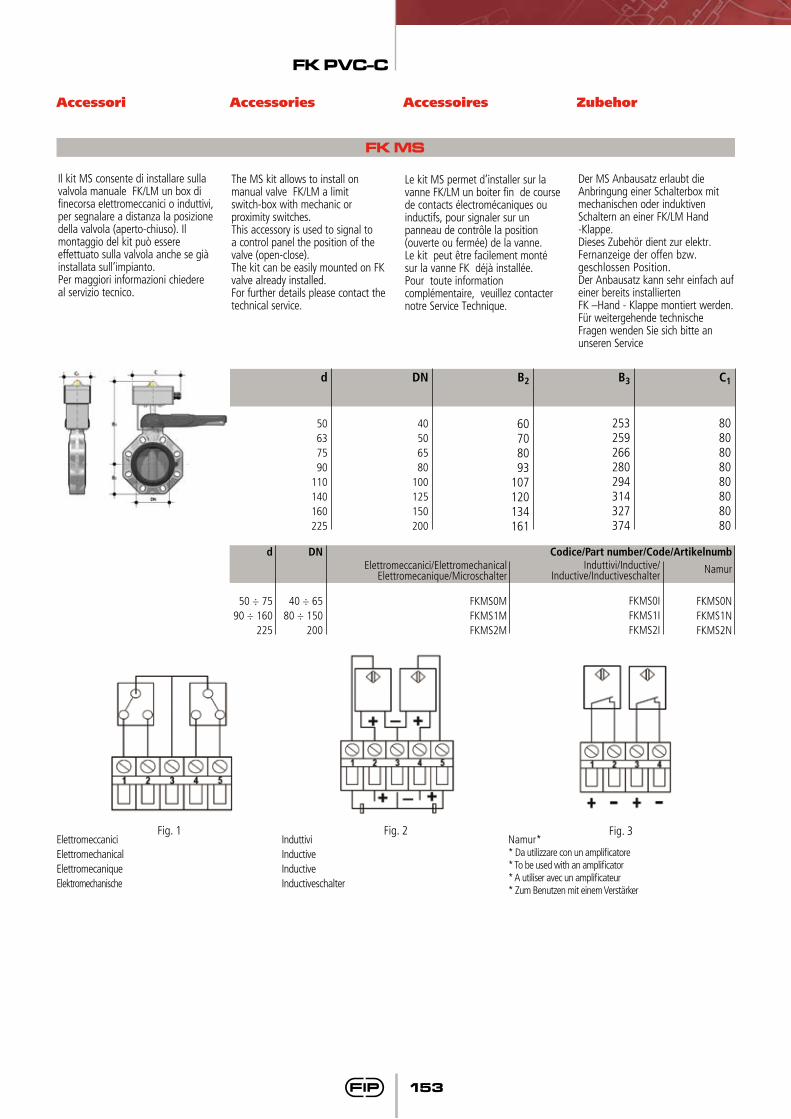
Il kit MS consente di installare sulla valvola manuale FK/LM un box di finecorsa elettromeccanici o induttivi, per segnalare a distanza la posizione della valvola (aperto-chiuso). Il montaggio del kit può essere effettuato sulla valvola anche se già installata sull’impianto.Per maggiori informazioni chiedere al servizio tecnico.
The MS kit allows to install on manual valve FK/LM a limit switch-box with mechanic or proximity switches.This accessory is used to signal to a control panel the position of the valve (open-close).The kit can be easily mounted on FK valve already installed.For further details please contact the technical service.
Le kit MS permet d’installer sur la vanne FK/LM un boiter fin de course de contacts électromécaniques ou inductifs, pour signaler sur un panneau de contrôle la position (ouverte ou fermée) de la vanne.Le kit peut être facilement monté sur la vanne FK déjà installée.Pour toute information complémentaire, veuillez contacter notre Service Technique.
Der MS Anbausatz erlaubt die Anbringung einer Schalterbox mit mechanischen oder induktiven Schaltern an einer FK/LM Hand -Klappe.Dieses Zubehör dient zur elektr. Fernanzeige der offen bzw. geschlossen Position.Der Anbausatz kann sehr einfach auf einer bereits installierten FK –Hand - Klappe montiert werden.Für weitergehende technische Fragen wenden Sie sich bitte an unseren Service
FK MS
d
50637590
110140160225
DN
40506580
100125150200
B3
253259266280294314327374
B2
60708093
107120134161
C1
8080808080808080
Fig. 3Fig. 1 Fig. 2ElettromeccaniciElettromechanicalElettromecaniqueElektromechanische
InduttiviInductiveInductiveInductiveschalter
Namur** Da utilizzare con un amplificatore* To be used with an amplificator* A utiliser avec un amplificateur* Zum Benutzen mit einem Verstärker
DN
40 ÷ 6580 ÷ 150
200
d
50 ÷ 7590 ÷ 160
225
Induttivi/Inductive/Inductive/Inductiveschalter
FKMS0IFKMS1IFKMS2I
Elettromeccanici/ElettromechanicalElettromecanique/Microschalter
FKMS0MFKMS1MFKMS2M
Codice/Part number/Code/Artikelnumb
Namur
FKMS0NFKMS1NFKMS2N
FK PVC-C
154
Automatismi Actuators Automatismes Antriebe
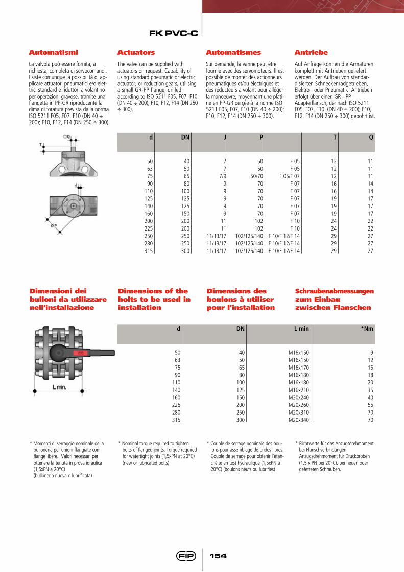
La valvola può essere fornita, a richiesta, completa di servocomandi. Esiste comunque la possibilità di ap-plicare attuatori pneumatici e/o elet-trici standard e riduttori a volantino per operazioni gravose, tramite una flangetta in PP-GR riproducente la dima di foratura prevista dalla norma ISO 5211 F05, F07, F10 (DN 40 ÷ 200); F10, F12, F14 (DN 250 ÷ 300).
Sur demande, la vanne peut être fournie avec des servomoteurs. Il est possible de monter des actionneurs pneumatiques et/ou électriques et des réducteurs à volant pour alléger la manoeuvre, moyennant une plati-ne en PP-GR perçée à la norme ISO 5211 F05, F07, F10 (DN 40 ÷ 200); F10, F12, F14 (DN 250 ÷ 300).
Auf Anfrage können die Armaturen komplett mit Antrieben geliefert werden. Der Aufbau von standar-disierten Schneckenradgetrieben, Elektro - oder Pneumatik -Antrieben erfolgt über einen GR - PP - Adapterflansch, der nach ISO 5211 F05, F07, F10 (DN 40 ÷ 200); F10, F12, F14 (DN 250 ÷ 300) gebohrt ist.
The valve can be supplied with actuators on request. Capability of using standard pneumatic or electric actuator, or reduction gears, utilising a small GR-PP flange, drilled according to ISO 5211 F05, F07, F10 (DN 40 ÷ 200); F10, F12, F14 (DN 250 ÷ 300).
Dimensioni dei bulloni da utilizzare nell’installazione
Dimensions of the bolts to be used in installation
Dimensions des boulons à utiliser pour l’installation
Schraubenabmessungen zum Einbau zwischen Flanschen
d
50637590
110125140160200225250280315
DN
40506580
100125125150200200250250300
J
77
7/999999
1111
11/13/1711/13/1711/13/17
P
5050
50/707070707070
102102
102/125/140102/125/140102/125/140
F 05F 05
F 05/F 07F 07F 07F 07F 07F 07F 10F 10
F 10/F 12/F 14F 10/F 12/F 14F 10/F 12/F 14
T
12121216161919192424292929
Q
11111114141717172222272727
d
50637590
110140160225280315
DN
40506580
100125150200250300
L min
M16x150M16x150M16x170M16x180M16x180M16x210M20x240M20x260M20x310M20x340
*Nm
9121518203540557070
* Momenti di serraggio nominale della bulloneria per unioni flangiate con flange libere. Valori necessari per ottenere la tenuta in prova idraulica (1,5xPN a 20°C)
(bulloneria nuova o lubrificata)
* Nominal torque required to tighten bolts of flanged joints. Torque required for watertight joints (1,5xPN at 20°C) (new or lubricated bolts)
* Couple de serrage nominale des bou-lons pour assemblage de brides libres. Couple de serrage pour obtenir l’étan-chéité en test hydraulique (1,5xPN à 20°C) (boulons neufs ou lubrifiés)
* Richtwerte für das Anzugsdrehmoment bei Flanschverbindungen. Anzugsdrehmoment für Druckproben (1,5 x PN bei 20°C), bei neuen oder gefetteten Schrauben.
FK PVC-C
155
Posizionamento delle lunette
Inserts positioning Positionnement des entretoises
Positionen der Zentriereinsätze
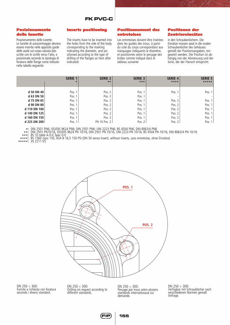
Posizionamento delle lunette.Le lunette di autocentraggio devono essere inserite nelle apposite guide delle asole sul corpo valvola lato scritte con le scritte verso l’alto, e posizionate secondo la tipologia di foratura delle flange come indicato nella tabella seguente:
The inserts have to be inserted into the holes from the side of the body corresponding to the marking indicating the diameter, and po-sitioned according to the type of drilling of the flanges as here after indicated:
Les entretoises doivent être insérées dans les guides des trous, à partir du coté du corps correspondant aux marquages indiquants le diamètre, et positionnés selon le perçage des brides comme indiqué dans le tableau suivante:
in den Schraubenlöchern. Die Einsätze müssen axial in die ovalen Schraubenlöcher des Gehäuses gemäß der Positionsangaben, ein-gesetzt werden. Die Position ist ab-hängig von der Abmessung und der Serie, der der Flansch entspricht.
d 50 DN 40d 63 DN 50d 75 DN 65d 90 DN 80
d 110 DN 100d 140 DN 125d 160 DN 150d 225 DN 200
SERIE 1*
Pos. 1Pos. 1Pos. 1Pos. 1Pos. 1Pos. 1Pos. 1Pos. 1
SERIE 2**
Pos. 2Pos. 2Pos. 2Pos. 2Pos. 2Pos. 2Pos. 2
PN 10 Pos. 2
SERIE 3***
Pos. 1Pos. 1Pos. 1Pos. 1Pos. 1Pos. 1Pos. 1Pos. 2
SERIE 4 ****
Pos. 1-
Pos. 2Pos. 2Pos. 2Pos. 2Pos. 2Pos. 2
SERIE 5*****
Pos. 1-
Pos. 1Pos. 1Pos. 1Pos. 1Pos. 1Pos. 1
*: DIN 2501 PN6; ISO/DIS 9624 PN6; DIN 2501 PN6; UNI 2223 PN6, BS 4504 PN6, DIN 8063/4 PN6 **: DIN 2501 PN10/16, ISO/DIS 9624 PN 10/16, DIN 2501 PN 10/16, UNI 2223 PN 10/16, BS 4504 PN 10/16, DIN 8063/4 PN 10/16 ***: BS 10 table A-D-E Spec D-E ****: BS 1560 class 150, ASA B 16,5 150 PSI (DN 50 senza inserti, without inserts, sans entretoise, ohne Einsätze) *****: JIS 2211 K5
POS. 1
POS. 2
DN 250 ÷ 300:Fornite a richiesta con foratura secondo i diversi standard.
DN 250 ÷ 300:Drilling on request according to different standards.
DN 250 ÷ 300:Perçage par trous selon plusiers standards internationaux sur demande.
DN 250 ÷ 300:Verfügbar mit Schraublöcher nach verschiedenen Normen gemaß Anfrage.
FK PVC-C
156
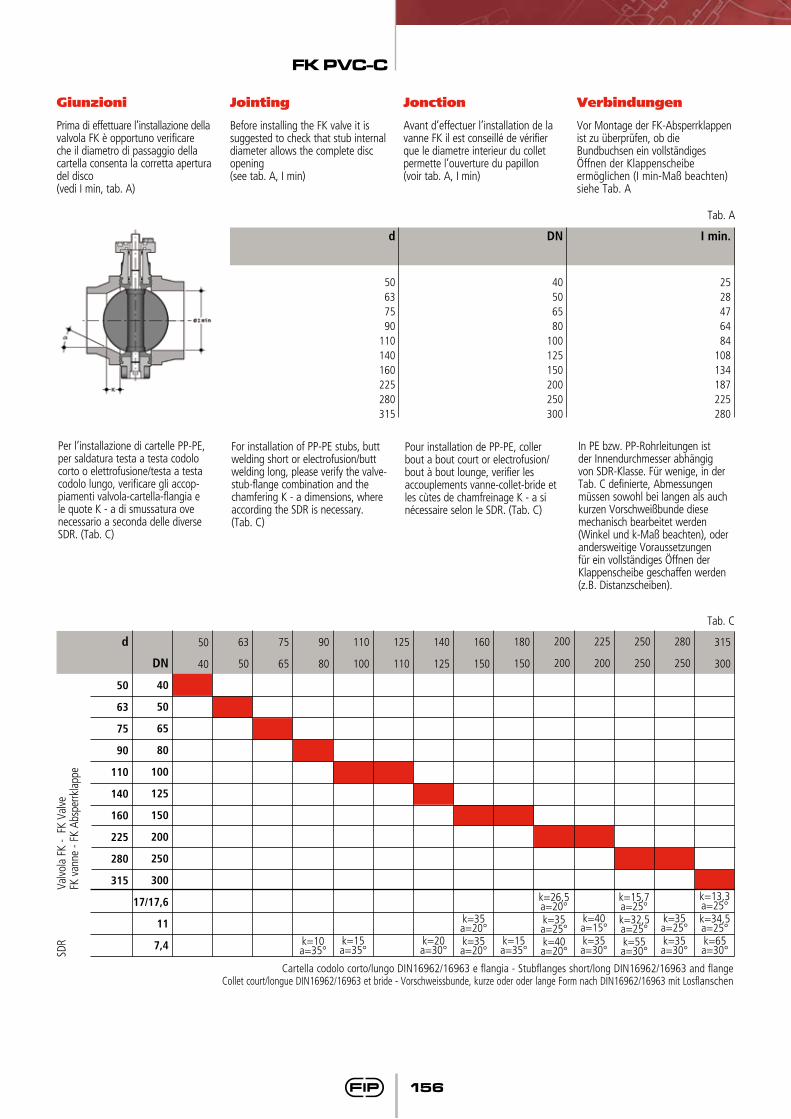
Giunzioni Jointing Jonction Verbindungen
Prima di effettuare l’installazione della valvola FK è opportuno verificare che il diametro di passaggio della cartella consenta la corretta apertura del disco (vedi I min, tab. A)
Avant d’effectuer l’installation de la vanne FK il est conseillé de vérifier que le diametre interieur du collet permette l’ouverture du papillon(voir tab. A, I min)
Vor Montage der FK-Absperrklappen ist zu überprüfen, ob die Bundbuchsen ein vollständiges Öffnen der Klappenscheibe ermöglichen (I min-Maß beachten)siehe Tab. A
Before installing the FK valve it is suggested to check that stub internal diameter allows the complete disc opening (see tab. A, I min)
Per l’installazione di cartelle PP-PE, per saldatura testa a testa codolo corto o elettrofusione/testa a testa codolo lungo, verificare gli accop-piamenti valvola-cartella-flangia e le quote K - a di smussatura ove necessario a seconda delle diverse SDR. (Tab. C)
For installation of PP-PE stubs, butt welding short or electrofusion/butt welding long, please verify the valve-stub-flange combination and the chamfering K - a dimensions, where according the SDR is necessary. (Tab. C)
Pour installation de PP-PE, coller bout a bout court or electrofusion/bout à bout lounge, verifier les accouplements vanne-collet-bride et les cùtes de chamfreinage K - a si nécessaire selon le SDR. (Tab. C)
In PE bzw. PP-Rohrleitungen ist der Innendurchmesser abhängig von SDR-Klasse. Für wenige, in der Tab. C definierte, Abmessungen müssen sowohl bei langen als auch kurzen Vorschweißbunde diese mechanisch bearbeitet werden (Winkel und k-Maß beachten), oder andersweitige Voraussetzungen für ein vollständiges Öffnen der Klappenscheibe geschaffen werden (z.B. Distanzscheiben).
d
50637590
110140160225280315
DN
40506580
100125150200250300
I min.
2528476484
108134187225280
Tab. A
k=40a=15°
k=15a=35°
k=10a=35°
k=20a=30°
k=15a=35°
k=35a=30°
k=35a=20°k=35a=20°
k=34,5a=25°k=65a=30°
k=35a=25°
k=13,3a=25°
k=32,5a=25°k=55a=30°
k=15,7a=25°
k=35a=25°k=40a=20°
k=26,5a=20°
k=35a=30°
Cartella codolo corto/lungo DIN16962/16963 e flangia - Stubflanges short/long DIN16962/16963 and flangeCollet court/longue DIN16962/16963 et bride - Vorschweissbunde, kurze oder oder lange Form nach DIN16962/16963 mit Losflanschen
d
50
63
75
90
110
140
160
225
280
315
50
40
63
50
75
65
90
80
110
100
125
110
140
125
160
150
180
150
200
200
225
200
250
250
280
250
315
300DN
40
50
65
80
100
125
150
200
250
300
17/17,6
11
7,4
Valvo
la F
K -
FK V
alve
FK v
anne
- FK
Abs
perrk
lapp
eSD
R
Tab. C
FK PVC-C
157
Installazione sull’impianto
Connection to the system
Montage sur l’installation
Einbau in einer Leitung
1) Prima di procedere all’installa-zione dei raccordi flangiati di collegamento, verificare che la luce libera di passaggio dei rac-cordi stessi permetta la corretta apertura della lente della valvola. Controllare inoltre la quota massima di accoppiamento per la guarnizione.
2) Inserire le lunette nei fori secondo la posizione indicata nella tabella, dal lato corrispondente alla scritta con D e DN per facilitare l’inserimento dei tiranti e l’ac-coppiamento con le flange (DN 40 ÷ 200).
3) Posizionare la valvola tra due collari con flange avendo cura di rispettare le quote di instal-lazione Z. Si consiglia di instal-lare sempre la valvola a lente parzialmente chiusa (non deve fuoriuscire dal corpo) e di evitare disassamenti delle flange, causa di possibili perdite verso l’ester-no.
4) Prima di effettuare il serraggio dei tiranti, si consiglia di aprire la lente, per non danneggiare la guarnizione. Serrare in modo omogeneo i tiranti di collega-mento, secondo la coppia no-minale indicata in tabella. Non occorre forzare il serraggio dei tiranti per ottenere una perfetta tenuta idraulica. Un eccessivo serraggio pregiudicherebbe il contenimento delle coppie di manovra della valvola.
5) La valvola è bidirezionale e può essere installata in qualsiasi posizione. Può inoltre essere montata a fine linea o serbatoio.
1) Fit operating handle to valve body, using bolt supplied.
Prior to jointing stub flanges to pipe, check that design of stub allows full opening of disc.
2) Push the inserts into the holes according to the position indi-cated in the table from the side engraved with the D and DN marking to make the connection with flanges and bolts easier (DN 40 ÷ 200).
3) Place the valve between two stub flanges. It is advisable to install the valve with the disc in the partially closed position and to make sure that no misalign-ment of the flanges occurs as it may cause leakage.
4) Before tightening the bolts, it is advisable to open the disc, in order not to damage the primary gasket. Connecting bolts must be tightened uniformly. Do not to exceed the nominal torque indicated in the table.
5) The valve is bi-directional and can be installed in any position. Additionally, it can be mounted at the line end or on a tank.
1) Au préalable procéder à l’in-stallation des collets et brides en vérifiant que l’espace libre permette l’ouverture correcte de la vanne. Controler aussi que la côte maximale permette l’accouplement correcte avec la manchette.
2) Insérer les entretoises dans les trous ovales selon la position indiquées dans la table, du côté correspondant au marquage D et DN pour faciliter le montage des tirants et l’accouplement avec les brides(DN 40 ÷ 200).
3) Positionner la vanne entre les deux extrémités des brides en respectant la côte d’installation Z definie.Il est conseillé d’installer la vanne à papillon partiellement fermé (il ne doit pas sortir du corps), et d’éviter tout désaligne-ment des brides. Ce désaligne-ment pourrait être la cause de défauts d’étanchéité.
4) Avant d’effectuer le serrage des boulons, il est conseillé d’ouvrir le papillon, pour ne pas endommager la manchette. Il est nécessaire de procéder au serrage homogène de l’ensemble des boulons de fixation afin de ne pas créer de contraintes irrégulières sur les brides, selon les couples de serrage nominale indiquées. Il n’est pas nécessaire de trop serrer les boulons pour obtenir une parfaite étanchéité hydraulique: un serrage excessif augmente les couples de
manoeuvre de la vanne.
5) La vanne, bidirectionnelle, peut être installée en toute position. En plus, elle peut être installée en toute position. En plus elle peut être installée à fin de ligne ou sur réservoir.
1) Vor dem Einbau ist zu überprüfen, ob die Einbaulänge (Z - Maß) der Klappe mit dem Abstand der Bunde der Vorschweißbunde/Bundbuchsen übereinstimmt und ob für die Klappenscheibe genügend Freiraum in den Bundbuchsen / Vorschweiß-bunden für ein vollständiges Öffnen zur Verfügung steht.
2) Für einen leichteren Einbau (Zentrierung der Schrauben und der Armatur) sind die Einsätze, entsprechend der d - bzw. DN - Angabe auf der Klappe, in die ovalen Schraubenlöcher
einzusetzen (DN 40 ÷ 200).
3) Die Klappe ist zwischen die mit Flanschen versehenen Bunde der Bundbuchsen / Vorschweißbunde einzusetzen. Es ist ratsam, daß die Klappe dabei in teil-geschlossenem Zustand ist. Es ist darauf zu achten, daß die Dichtungs-auflageflächen der Vorschweißbunde/Bundbuchsen planparallel zueinander stehen, da es sonst zu Undichtheiten kommen kann.
4) Bevor die Schrauben angezogen werden, sollte die Klappenscheibe geöffnet werden um zu vermeiden,
daß die Auskleidung/Dichtung beschädigt wird. Die Schrauben müssen gleichmäßig über Kreuz angezogen werden. Die im folgenden noch angegebenen Anzugsdrehmomente dürfen nicht überschritten werden. Für eine korrekte Abdichtung ist es nicht notwendig, die Schrauben übermäßig anzuziehen. Dieses könnte das Betätigungsmoment der Absperrklappe erhöhen.
5) Die Durchflußrichtung ist beliebig (bidirektional) ebenso
die Einbaulage. Weiterhin kann die Klappe als Abschlußarmatur am Ende einer Rohrleitung oder als Tankauslaß eingesetzt
werden.
FK PVC-C
158
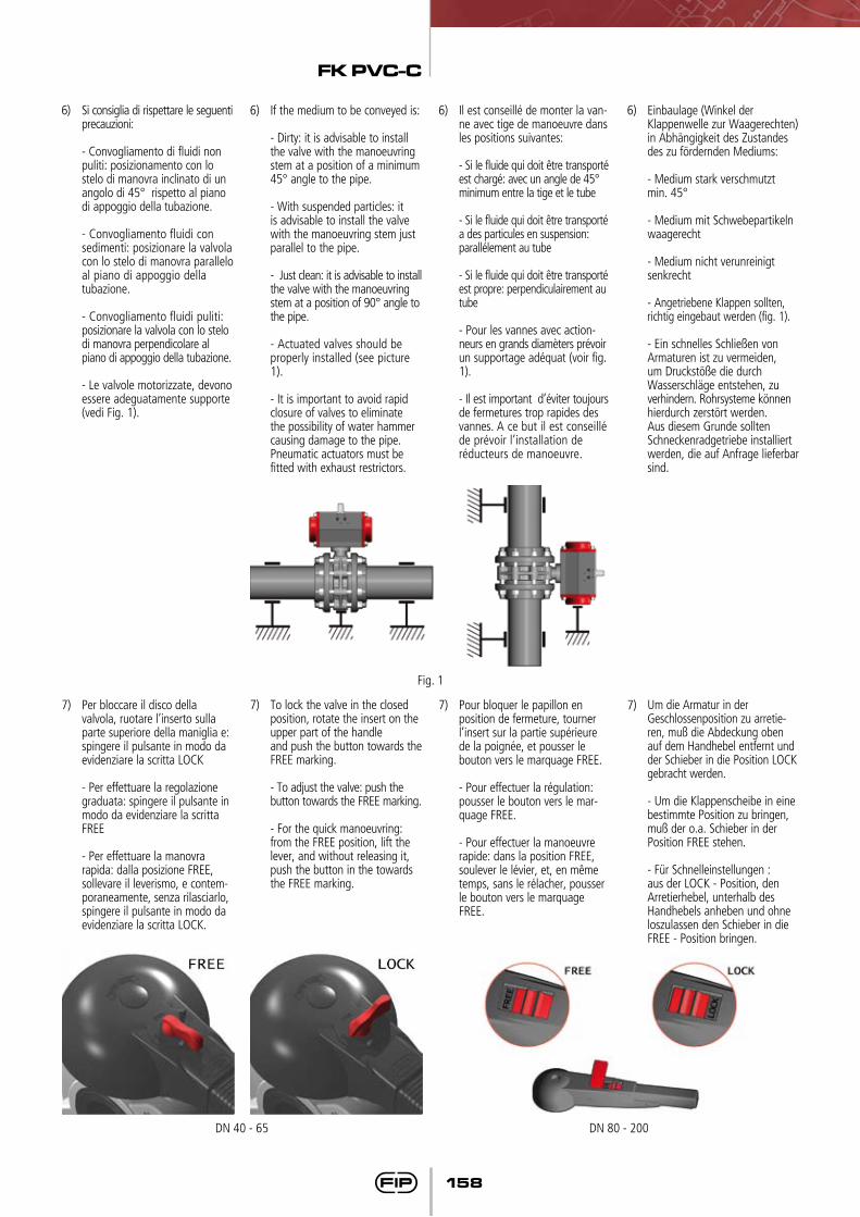
6) Si consiglia di rispettare le seguenti precauzioni:
- Convogliamento di fluidi non puliti: posizionamento con lo stelo di manovra inclinato di un angolo di 45° rispetto al piano di appoggio della tubazione.
- Convogliamento fluidi con sedimenti: posizionare la valvola con lo stelo di manovra parallelo al piano di appoggio della
tubazione.
- Convogliamento fluidi puliti: posizionare la valvola con lo stelo
di manovra perpendicolare al piano di appoggio della tubazione. - Le valvole motorizzate, devono
essere adeguatamente supporte (vedi Fig. 1).
6) Il est conseillé de monter la van-ne avec tige de manoeuvre dans les positions suivantes:
- Si le fluide qui doit être transporté est chargé: avec un angle de 45° minimum entre la tige et le tube
- Si le fluide qui doit être transporté a des particules en suspension: parallélement au tube
- Si le fluide qui doit être transporté est propre: perpendiculairement au tube
- Pour les vannes avec action-neurs en grands diamèters prévoir un supportage adéquat (voir fig. 1).
- Il est important d’éviter toujours de fermetures trop rapides des vannes. A ce but il est conseillé de prévoir l’installation de réducteurs de manoeuvre.
6) Einbaulage (Winkel der Klappenwelle zur Waagerechten) in Abhängigkeit des Zustandes des zu fördernden Mediums:
- Medium stark verschmutzt min. 45°
- Medium mit Schwebepartikeln waagerecht
- Medium nicht verunreinigt senkrecht
- Angetriebene Klappen sollten, richtig eingebaut werden (fig. 1).
- Ein schnelles Schließen von Armaturen ist zu vermeiden, um Druckstöße die durch Wasserschläge entstehen, zu verhindern. Rohrsysteme können hierdurch zerstört werden. Aus diesem Grunde sollten Schneckenradgetriebe installiert werden, die auf Anfrage lieferbar sind.
6) If the medium to be conveyed is:
- Dirty: it is advisable to install the valve with the manoeuvring stem at a position of a minimum 45° angle to the pipe.
- With suspended particles: it is advisable to install the valve with the manoeuvring stem just parallel to the pipe.
- Just clean: it is advisable to install the valve with the manoeuvring stem at a position of 90° angle to the pipe.
- Actuated valves should be properly installed (see picture 1).
- It is important to avoid rapid closure of valves to eliminate the possibility of water hammer causing damage to the pipe. Pneumatic actuators must be fitted with exhaust restrictors.
Fig. 1
7) Per bloccare il disco della valvola, ruotare l’inserto sulla parte superiore della maniglia e: spingere il pulsante in modo da evidenziare la scritta LOCK
- Per effettuare la regolazione graduata: spingere il pulsante in modo da evidenziare la scritta FREE
- Per effettuare la manovra rapida: dalla posizione FREE, sollevare il leverismo, e contem-poraneamente, senza rilasciarlo, spingere il pulsante in modo da evidenziare la scritta LOCK.
7) Pour bloquer le papillon en position de fermeture, tourner
l’insert sur la partie supérieure de la poignée, et pousser le
bouton vers le marquage FREE.
- Pour effectuer la régulation: pousser le bouton vers le mar-quage FREE.
- Pour effectuer la manoeuvre rapide: dans la position FREE, soulever le lévier, et, en même temps, sans le rélacher, pousser le bouton vers le marquage FREE.
7) Um die Armatur in der Geschlossenposition zu arretie-ren, muß die Abdeckung oben auf dem Handhebel entfernt und der Schieber in die Position LOCK gebracht werden.
- Um die Klappenscheibe in eine bestimmte Position zu bringen, muß der o.a. Schieber in der Position FREE stehen.
- Für Schnelleinstellungen : aus der LOCK - Position, den Arretierhebel, unterhalb des Handhebels anheben und ohne loszulassen den Schieber in die FREE - Position bringen.
7) To lock the valve in the closed position, rotate the insert on the upper part of the handle and push the button towards the FREE marking.
- To adjust the valve: push the button towards the FREE marking.
- For the quick manoeuvring: from the FREE position, lift the lever, and without releasing it, push the button in the towards the FREE marking.
DN 40 - 65 DN 80 - 200
FK PVC-C
159
Smontaggio(DN 40÷200)
Disassembly(DN 40÷200)
Démontage(DN 40÷200)
Demontage(DN 40÷200)
Montaggio(DN 40÷200)
Assembly(DN 40÷200)
Montage(DN 40÷200)
Montage(DN 40÷200)
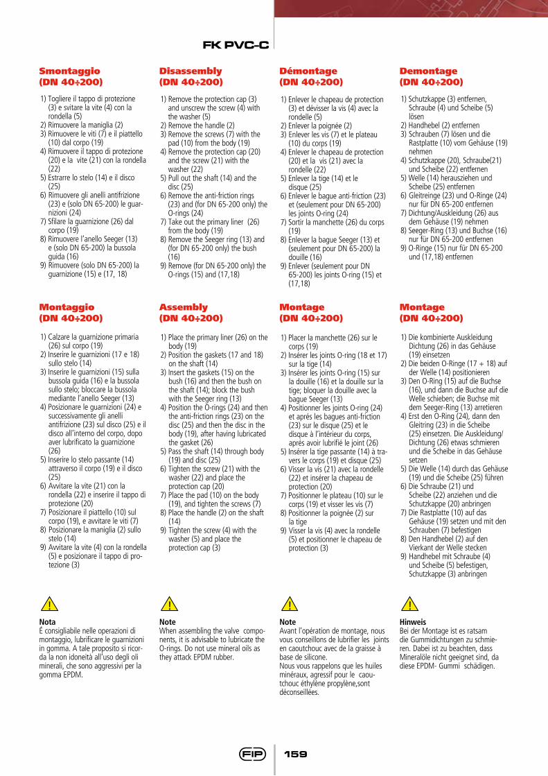
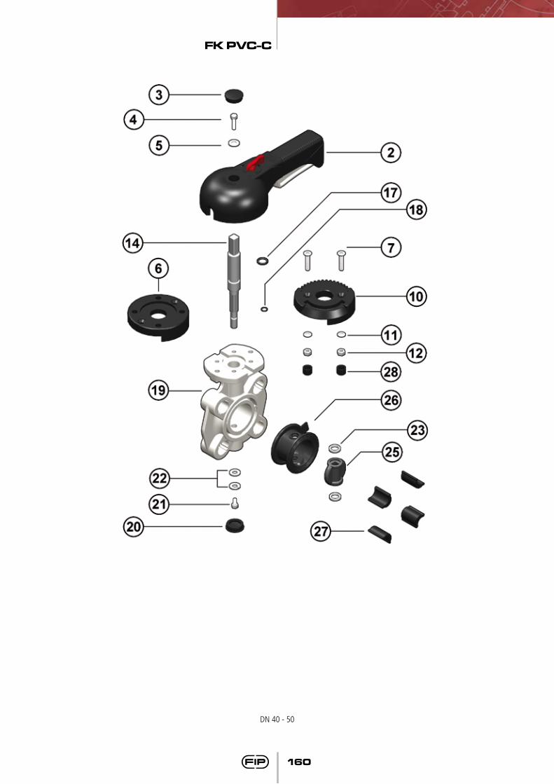
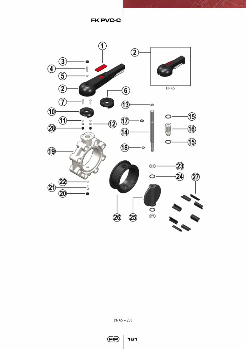
1) Togliere il tappo di protezione (3) e svitare la vite (4) con la rondella (5)
2) Rimuovere la maniglia (2)3) Rimuovere le viti (7) e il piattello
(10) dal corpo (19)4) Rimuovere il tappo di protezione
(20) e la vite (21) con la rondella (22)
5) Estrarre lo stelo (14) e il disco (25)
6) Rimuovere gli anelli antifrizione (23) e (solo DN 65-200) le guar-nizioni (24)
7) Sfilare la guarnizione (26) dal corpo (19)
8) Rimuovere l’anello Seeger (13) e (solo DN 65-200) la bussola guida (16)
9) Rimuovere (solo DN 65-200) la guarnizione (15) e (17, 18)
1) Remove the protection cap (3) and unscrew the screw (4) with the washer (5)
2) Remove the handle (2)3) Remove the screws (7) with the
pad (10) from the body (19)4) Remove the protection cap (20)
and the screw (21) with the washer (22)5) Pull out the shaft (14) and the
disc (25)6) Remove the anti-friction rings
(23) and (for DN 65-200 only) the O-rings (24)
7) Take out the primary liner (26) from the body (19)
8) Remove the Seeger ring (13) and (for DN 65-200 only) the bush (16)
9) Remove (for DN 65-200 only) the O-rings (15) and (17,18)
1) Enlever le chapeau de protection (3) et dévisser la vis (4) avec la rondelle (5)
2) Enlever la poignée (2)3) Enlever les vis (7) et le plateau
(10) du corps (19)4) Enlever le chapeau de protection
(20) et la vis (21) avec la rondelle (22)5) Enlever la tige (14) et le disque (25)6) Enlever le bague anti-friction (23)
et (seulement pour DN 65-200) les joints O-ring (24)
7) Sortir la manchette (26) du corps (19)
8) Enlever la bague Seeger (13) et (seulement pour DN 65-200) la douille (16)
9) Enlever (seulement pour DN 65-200) les joints O-ring (15) et (17,18)
1) Schutzkappe (3) entfernen, Schraube (4) und Scheibe (5) lösen
2) Handhebel (2) entfernen3) Schrauben (7) lösen und die
Rastplatte (10) vom Gehäuse (19) nehmen
4) Schutzkappe (20), Schraube(21) und Scheibe (22) entfernen
5) Welle (14) herausziehen und Scheibe (25) entfernen
6) Gleitreinge (23) und O-Ringe (24) nur für DN 65-200 entfernen
7) Dichtung/Auskleidung (26) aus dem Gehäuse (19) nehmen
8) Seeger-Ring (13) und Buchse (16) nur für DN 65-200 entfernen
9) O-Ringe (15) nur für DN 65-200 und (17,18) entfernen
1) Calzare la guarnizione primaria (26) sul corpo (19)
2) Inserire le guarnizioni (17 e 18) sullo stelo (14)
3) Inserire le guarnizioni (15) sulla bussola guida (16) e la bussola sullo stelo; bloccare la bussola mediante l’anello Seeger (13)
4) Posizionare le guarnizioni (24) e successivamente gli anelli
antifrizione (23) sul disco (25) e il disco all’interno del corpo, dopo aver lubrificato la guarnizione (26)
5) Inserire lo stelo passante (14) attraverso il corpo (19) e il disco
(25)6) Avvitare la vite (21) con la rondella (22) e inserire il tappo di
protezione (20)7) Posizionare il piattello (10) sul
corpo (19), e avvitare le viti (7)8) Posizionare la maniglia (2) sullo
stelo (14)9) Avvitare la vite (4) con la rondella
(5) e posizionare il tappo di pro-tezione (3)
1) Place the primary liner (26) on the body (19)
2) Position the gaskets (17 and 18) on the shaft (14)
3) Insert the gaskets (15) on the bush (16) and then the bush on the shaft (14); block the bush with the Seeger ring (13)
4) Position the O-rings (24) and then the anti-friction rings (23) on the disc (25) and then the disc in the body (19), after having lubricated the gasket (26)
5) Pass the shaft (14) through body (19) and disc (25)
6) Tighten the screw (21) with the washer (22) and place the
protection cap (20)7) Place the pad (10) on the body
(19), and tighten the screws (7)8) Place the handle (2) on the shaft
(14)9) Tighten the screw (4) with the
washer (5) and place the protection cap (3)
1) Placer la manchette (26) sur le corps (19)
2) Insérer les joints O-ring (18 et 17) sur la tige (14)
3) Insérer les joints O-ring (15) sur la douille (16) et la douille sur la tige; bloquer la douille avec la bague Seeger (13)
4) Positionner les joints O-ring (24) et aprés les bagues anti-friction (23) sur le disque (25) et le
disque à l’intérieur du corps, aprés avoir lubrifié le joint (26)
5) Insérer la tige passante (14) à tra-vers le corps (19) et disque (25)
6) Visser la vis (21) avec la rondelle (22) et insérer la chapeau de
protection (20)7) Positionner le plateau (10) sur le
corps (19) et visser les vis (7)8) Positionner la poignée (2) sur
la tige9) Visser la vis (4) avec la rondelle
(5) et positionner le chapeau de protection (3)
1) Die kombinierte Auskleidung Dichtung (26) in das Gehäuse (19) einsetzen
2) Die beiden O-Ringe (17 + 18) auf der Welle (14) positionieren
3) Den O-Ring (15) auf die Buchse (16), und dann die Buchse auf die Welle schieben; die Buchse mit dem Seeger-Ring (13) arretieren
4) Erst den O-Ring (24), dann den Gleitring (23) in die Scheibe (25) einsetzen. Die Auskleidung/Dichtung (26) etwas schmieren und die Scheibe in das Gehäuse setzen
5) Die Welle (14) durch das Gehäuse (19) und die Scheibe (25) führen
6) Die Schraube (21) und Scheibe (22) anziehen und die Schutzkappe (20) anbringen
7) Die Rastplatte (10) auf das Gehäuse (19) setzen und mit den Schrauben (7) befestigen
8) Den Handhebel (2) auf den Vierkant der Welle stecken
9) Handhebel mit Schraube (4) und Scheibe (5) befestigen, Schutzkappe (3) anbringen
NotaÉ consigliabile nelle operazioni di montaggio, lubrificare le guarnizioni in gomma. A tale proposito si ricor-da la non idoneità all’uso degli oli minerali, che sono aggressivi per la gomma EPDM.
NoteWhen assembling the valve compo-nents, it is advisable to lubricate the O-rings. Do not use mineral oils as they attack EPDM rubber.
NoteAvant l’opération de montage, nous vous conseillons de lubrifier les joints en caoutchouc avec de la graisse à base de silicone.Nous vous rappelons que les huiles minéraux, agressif pour le caou-tchouc éthylène propylène,sont déconseillées.
HinweisBei der Montage ist es ratsam die Gummidichtungen zu schmie-ren. Dabei ist zu beachten, dass Mineralöle nicht geeignet sind, da diese EPDM- Gummi schädigen.
FK PVC-C
160
DN 40 - 50
FK PVC-C
161
DN 65 ÷ 200
DN 65
FK PVC-C
162
Q.té
111111212211211111112211
4-82
Materiaux
ABSHIPVC
PEAcier inoxAcier inox
PP-GRAcier inox
PP-GRAcier inoxAcier inoxAcier inoxAcier inox
EPDM ou FPMNylon
EPDM ou FPMEPDM ou FPM
PP-GRPE
Acier inoxAcier inox
PTFEEPDM ou FPM
PVC-CEPDM ou FPM
ABSPE
Pos.
1234567
10111213141516171819202122232425262728
Composants
Insert poignéePoignée
Chapeau de protectionVis de fixation
RondelleBride
VisPlateau
RondelleEcrou
Bague SeegerTige
O-ring douilleDouille
O-ring tigeO-ring tige
CorpsChapeau de protection
VisRondelle
Bague anti-frictionO-ring papillon
PapillonManchetteEntretoises
Bouchon de protection
Q.tà
111111212211211111112211
4-82
Materiale
ABSHIPVC
PEAcciaio inoxAcciaio inox
PP-GRAcciaio inox
PP-GRAcciaio inoxAcciaio inoxAcciaio inoxAcciaio inox
EPDM o FPMNylon
EPDM o FPMEPDM o FPM
PP-GRPE
Acciaio inoxAcciaio inox
PTFEEPDM o FPM
PVC-CEPDM o FPM
ABSPE
Pos.
1234567
10111213141516171819202122232425262728
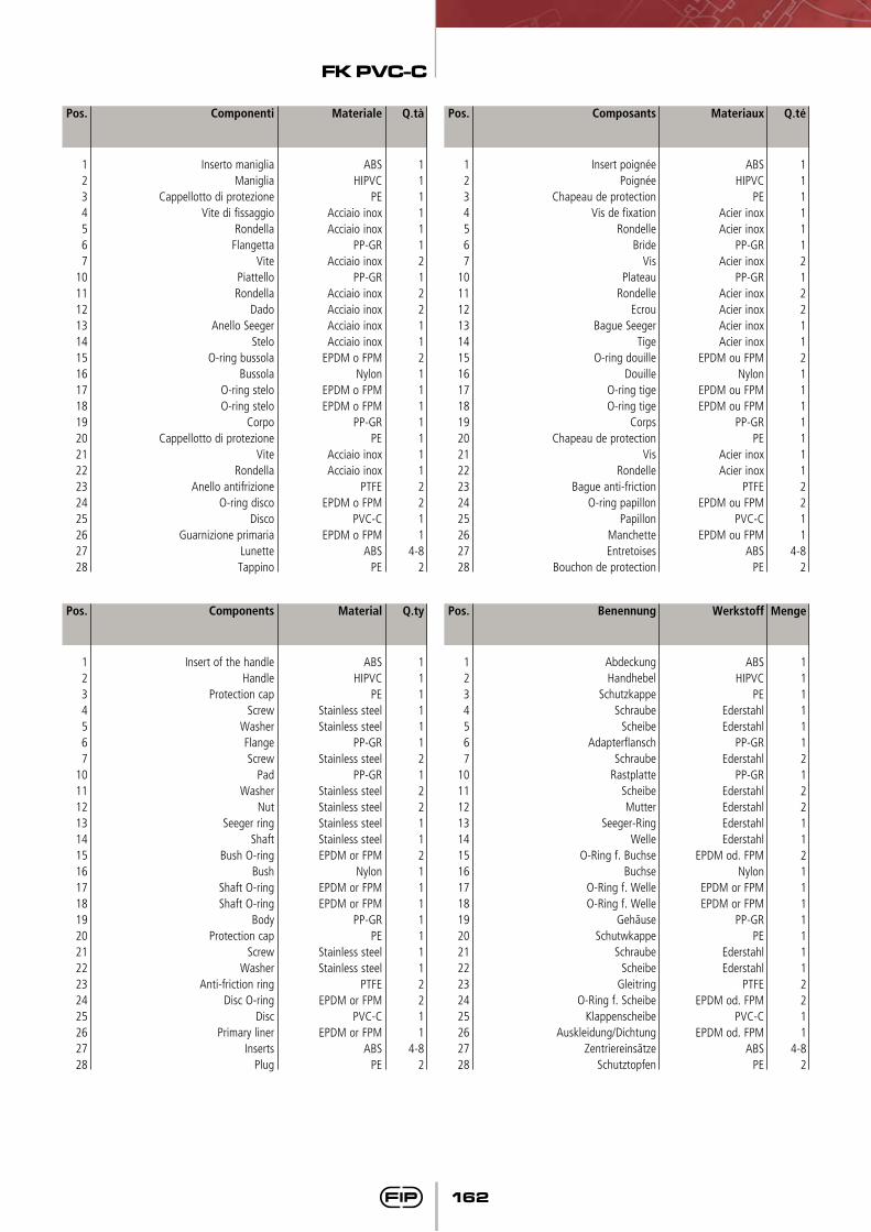
Componenti
Inserto manigliaManiglia
Cappellotto di protezioneVite di fissaggio
RondellaFlangetta
VitePiattelloRondella
DadoAnello Seeger
SteloO-ring bussola
BussolaO-ring steloO-ring stelo
CorpoCappellotto di protezione
ViteRondella
Anello antifrizioneO-ring disco
DiscoGuarnizione primaria
LunetteTappino
Menge
111111212211211111112211
4-82
Werkstoff
ABSHIPVC
PEEderstahlEderstahl
PP-GREderstahl
PP-GREderstahlEderstahlEderstahlEderstahl
EPDM od. FPMNylon
EPDM or FPMEPDM or FPM
PP-GRPE
EderstahlEderstahl
PTFEEPDM od. FPM
PVC-CEPDM od. FPM
ABSPE
Pos.
1234567
10111213141516171819202122232425262728
Q.ty
111111212211211111112211
4-82
Material
ABSHIPVC
PEStainless steelStainless steel
PP-GRStainless steel
PP-GRStainless steelStainless steelStainless steelStainless steelEPDM or FPM
NylonEPDM or FPMEPDM or FPM
PP-GRPE
Stainless steelStainless steel
PTFEEPDM or FPM
PVC-CEPDM or FPM
ABSPE
Pos.
1234567
10111213141516171819202122232425262728
Components
Insert of the handleHandle
Protection capScrew
WasherFlangeScrew
PadWasher
NutSeeger ring
ShaftBush O-ring
BushShaft O-ringShaft O-ring
BodyProtection cap
ScrewWasher
Anti-friction ringDisc O-ring
DiscPrimary liner
InsertsPlug
Benennung
AbdeckungHandhebel
SchutzkappeSchraube
ScheibeAdapterflansch
SchraubeRastplatte
ScheibeMutter
Seeger-RingWelle
O-Ring f. BuchseBuchse
O-Ring f. WelleO-Ring f. Welle
GehãuseSchutwkappe
SchraubeScheibe
GleitringO-Ring f. Scheibe
KlappenscheibeAuskleidung/Dichtung
ZentriereinsãtzeSchutztopfen
FK PVC-C
163
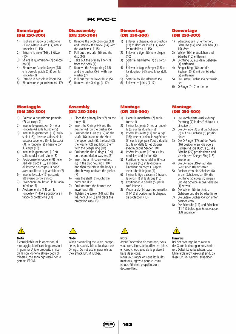
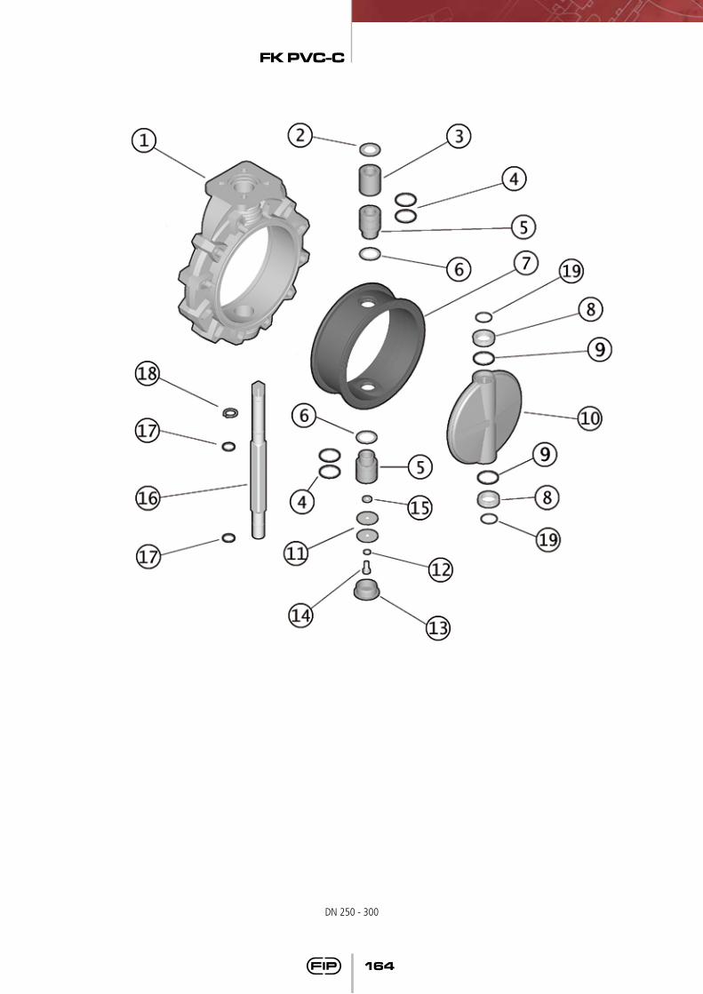
Smontaggio(DN 250-300)
Disassembly(DN 250-300)
Démontage(DN 250-300)
Demontage(DN 250-300)
1) Togliere il tappo di protezione (13) e svitare la vite (14) con le rondelle (11-15)
2) Estrarre lo stelo (16) e il disco (10)
3) Sfilare la guarnizione (7) dal cor-po (1)
4) Rimuovere l’anello Seeger (18) e le bussole guida (5-3) con la rondella (2)
5) Estrarre la bussola inferiore (5)6) Rimuovere le guarnizioni (4–17)
1) Remove the protection cap (13) and unscrew the screw (14) with the washers (11-15)
2) Pull out the shaft (16) and the disc (10)
3) Take out the primary liner (7) from the body (1)
4) Remove the Seeger ring ( 18) and the bushes (5-3) with the washer (2)
5) Pull out the the lower bush (5)6) Remove the O-rings (4-17)
1) Enlever le chapeau de protection (13) et dévisser la vis (14) avec les rondelles (11-15)
2) Enlever la tige (16) et le disque (10)
3) Sortir la manchette (7) du corps (1)
4) Enlever la bague Seeger (18) et les douilles (5-3) avec la rondelle (2)
5) Sortir la douille inférieure (5)6) Enlever les joints (4-17)
1) Schutzkappe (13) entfernen, Schraube (14) und Scheiben (11-15) lösen
2) Welle (16) herausziehen und Scheibe (10) entfernen
3) Dichtung (7) aus dem Gehäuse (1) entfernen
4) Seeger-Ring (18) und die Buchsen (5-3) mit der Scheibe (2) entfernen
5) Die untere Buchse (5) herauszie-hen
6) O-Ringe (4-17) entfernen
Montaggio(DN 250-300)
Assembly(DN 250-300)
Montage(DN 250-300)
Montage(DN 250-300)
1) Calzare la guarnizione primaria (7) sul corpo (1)
2) Inserire le guarnizioni (4) e la rondella (6) sulle bussole (5)
3) Inserire le guarnizioni (17) sullo stelo (16); inserire sullo stelo la bussola superiore (5), la bussola (3), la rondella (2) e fissarle con il Seeger (18)
4) Inserire le guarnizioni (19-9) sulle rondelle anifrizione (8)
5) Posizionare le rondelle (8) nelle sedi del disco (10), e il disco all’interno del corpo (1) dopo aver lubrificato la guarnizione (7)
6) Inserire lo stelo (16) passante attraverso corpo e disco
7) Posizionare dal basso la bussola inferiore (5)
8) Avvitare le vite (14) con le rondelle (11-15) e posizionare il tappo di protezione (13)
1) Place the primary liner (7) on the body (1)
2) Insert the O-rings (4) and the washer (6) on the bushes (5)
3) Position the O-rings (17) on the shaft (16), insert on the shaft the upper bush (5), the bush (3), the washer (2) and block them with the Seeger ring (18)
4) Position the the O-rings (19-9) on the antifriction washers (8)
5) Insert the antifriction washers (8) in the disc housings (10), and then the disc in the body (1) after having lubricate the gasket (7)
6) Pass the shaft throught the body and disc
7) Position from the bottom the lower bush (5)
8) Tighten the screw (14) with the washers (11-15) and place the protection cap (13)
1) Placer la manchette (7) sur le corps (1)
2) Insérer les joints (4) et la rondel-le (6) sur les douilles (5)
3) Insérer les joints (17) sur la tige (16); insérer la douille supérieure (5) sur la tige, puis l’autre douille (3), la rondelle (2) et bloquer avec la bague Seeger (18)
4) Insérer les joints (19-9) sur les rondelles anti-friction (8)
5) Positionner les rondelles (8) sur le disque (10) et le disque à
l’intérieur du corps (1) après avoir lubrifié le joint (7)
6) Insérer la tige passante à travers le corps (1) et le disque (10)
7) Positionner la douille (5) par le coté inférieur
8) Visser la vis (14) avec les rondelles (11-15) et positionner le chapeau de protection (13)
1) Die kombinierte Auskleidung/Dichtung (7) in das Gehäuse (1) einsetzen.
2) Die O-Ringe (4) und die Scheibe (6) auf die Buchsen (5) positio-nieren
3) Die O-Ringe (17) auf der Welle (16) positionieren; die obere Buchse (5), die Buchse (3) die Scheibe (22) positionieren und sie mit dem Seeger-Ring (18) arretieren
4) Die O-Ringe (19-9) auf den Gleitringen (8) einsetzen
5) Positionieren die Scheiben (8) in den Scheibensitz (10), die Dichtung (7) etwas schmieren und die Scheibe in das Gehäuse (1) setzen
6) Die Welle (16) durch das Gehäuse und die Scheibe führen
7) Die untere Buchse (5) von unten positionieren
8) Die Schraube (14) und Scheiben (11-15) befestigen Schutzkappe (13) anbringen
NotaÉ consigliabile nelle operazioni di montaggio, lubrificare le guarnizioni in gomma. A tale proposito si ricor-da la non idoneità all’uso degli oli minerali, che sono aggressivi per la gomma EPDM.
NoteWhen assembling the valve compo-nents, it is advisable to lubricate the O-rings. Do not use mineral oils as they attack EPDM rubber.
NoteAvant l’opération de montage, nous vous conseillons de lubrifier les joints en caoutchouc avec de la graisse à base de silicone.Nous vous rappelons que les huiles minéraux, agressif pour le caou-tchouc éthylène propylène,sont déconseillées.
HinweisBei der Montage ist es ratsam die Gummidichtungen zu schmie-ren. Dabei ist zu beachten, dass Mineralöle nicht geeignet sind, da diese EPDM- Gummi schädigen.
FK PVC-C
164
DN 250 - 300
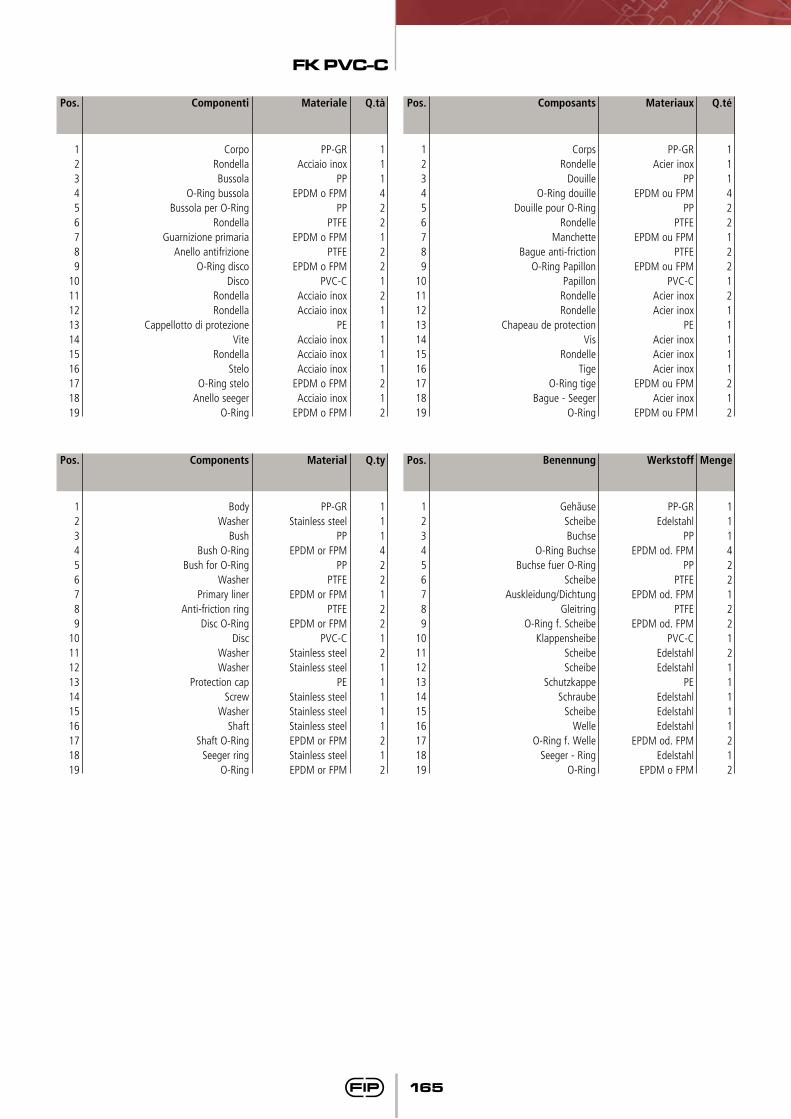
FK PVC-C
165
Q.té
1114221221211111212
Materiaux
PP-GRAcier inox
PPEPDM ou FPM
PPPTFE
EPDM ou FPMPTFE
EPDM ou FPMPVC-C
Acier inoxAcier inox
PEAcier inoxAcier inoxAcier inox
EPDM ou FPMAcier inox
EPDM ou FPM
Pos.
123456789
10111213141516171819
Composants
CorpsRondelle
DouilleO-Ring douille
Douille pour O-RingRondelle
ManchetteBague anti-friction
O-Ring PapillonPapillon
RondelleRondelle
Chapeau de protectionVis
RondelleTige
O-Ring tigeBague - Seeger
O-Ring
Q.tà
1114221221211111212
Materiale
PP-GRAcciaio inox
PPEPDM o FPM
PPPTFE
EPDM o FPMPTFE
EPDM o FPMPVC-C
Acciaio inoxAcciaio inox
PEAcciaio inoxAcciaio inoxAcciaio inox
EPDM o FPMAcciaio inox
EPDM o FPM
Pos.
123456789
10111213141516171819
Componenti
CorpoRondellaBussola
O-Ring bussolaBussola per O-Ring
RondellaGuarnizione primaria
Anello antifrizioneO-Ring disco
DiscoRondellaRondella
Cappellotto di protezioneVite
RondellaStelo
O-Ring steloAnello seeger
O-Ring
Menge
1114221221211111212
Werkstoff
PP-GREdelstahl
PPEPDM od. FPM
PPPTFE
EPDM od. FPMPTFE
EPDM od. FPMPVC-C
EdelstahlEdelstahl
PEEdelstahlEdelstahl Edelstahl
EPDM od. FPMEdelstahl
EPDM o FPM
Pos.
123456789
10111213141516171819
Q.ty
1114221221211111212
Material
PP-GRStainless steel
PPEPDM or FPM
PPPTFE
EPDM or FPMPTFE
EPDM or FPMPVC-C
Stainless steelStainless steel
PEStainless steelStainless steelStainless steelEPDM or FPMStainless steelEPDM or FPM
Pos.
123456789
10111213141516171819
Components
BodyWasher
BushBush O-Ring
Bush for O-RingWasher
Primary linerAnti-friction ring
Disc O-RingDisc
WasherWasher
Protection capScrew
WasherShaft
Shaft O-RingSeeger ring
O-Ring
Benennung
GehãuseScheibeBuchse
O-Ring BuchseBuchse fuer O-Ring
ScheibeAuskleidung/Dichtung
GleitringO-Ring f. Scheibe
KlappensheibeScheibeScheibe
SchutzkappeSchraube
ScheibeWelle
O-Ring f. WelleSeeger - Ring
O-Ring
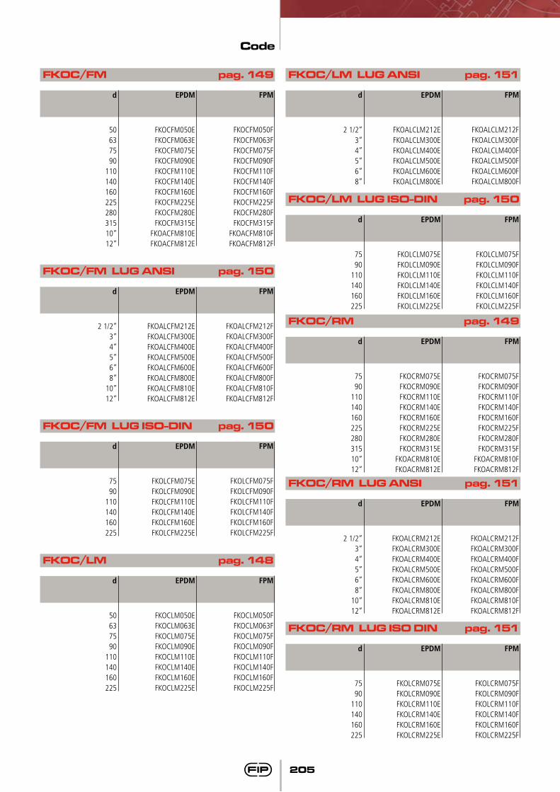
Code
205
FKOC/FM pag. 149
FKOC/FM LUG ANSI pag. 150
FKOC/FM LUG ISO-DIN pag. 150
FKOC/LM pag. 148
FKOC/LM LUG ANSI pag. 151
d
50637590
11014016022528031510”12”
d
2 1/2”3”4”5”6”8”
10”12”
d
7590
110140160225
d
50637590
110140160225
d
2 1/2”3”4”5”6”8”
EPDM
FKOCFM050EFKOCFM063EFKOCFM075EFKOCFM090EFKOCFM110EFKOCFM140EFKOCFM160EFKOCFM225EFKOCFM280EFKOCFM315E
FKOACFM810EFKOACFM812E
EPDM
FKOALCFM212EFKOALCFM300EFKOALCFM400EFKOALCFM500EFKOALCFM600EFKOALCFM800EFKOALCFM810EFKOALCFM812E
EPDM
FKOLCFM075EFKOLCFM090EFKOLCFM110EFKOLCFM140EFKOLCFM160EFKOLCFM225E
EPDM
FKOCLM050EFKOCLM063EFKOCLM075EFKOCLM090EFKOCLM110EFKOCLM140EFKOCLM160EFKOCLM225E
EPDM
FKOALCLM212EFKOALCLM300EFKOALCLM400EFKOALCLM500EFKOALCLM600EFKOALCLM800E
FPM
FKOCFM050FFKOCFM063FFKOCFM075FFKOCFM090FFKOCFM110FFKOCFM140FFKOCFM160FFKOCFM225FFKOCFM280FFKOCFM315F
FKOACFM810FFKOACFM812F
FPM
FKOALCFM212FFKOALCFM300FFKOALCFM400FFKOALCFM500FFKOALCFM600FFKOALCFM800FFKOALCFM810FFKOALCFM812F
FPM
FKOLCFM075FFKOLCFM090FFKOLCFM110FFKOLCFM140FFKOLCFM160FFKOLCFM225F
FPM
FKOCLM050FFKOCLM063FFKOCLM075FFKOCLM090FFKOCLM110FFKOCLM140FFKOCLM160FFKOCLM225F
FPM
FKOALCLM212FFKOALCLM300FFKOALCLM400FFKOALCLM500FFKOALCLM600FFKOALCLM800F
FKOC/LM LUG ISO-DIN pag. 150
d
7590
110140160225
EPDM
FKOLCLM075EFKOLCLM090EFKOLCLM110EFKOLCLM140EFKOLCLM160EFKOLCLM225E
FPM
FKOLCLM075FFKOLCLM090FFKOLCLM110FFKOLCLM140FFKOLCLM160FFKOLCLM225F
FKOC/RM pag. 149
d
7590
11014016022528031510”12”
EPDM
FKOCRM075EFKOCRM090EFKOCRM110EFKOCRM140EFKOCRM160EFKOCRM225EFKOCRM280EFKOCRM315E
FKOACRM810EFKOACRM812E
FPM
FKOCRM075FFKOCRM090FFKOCRM110FFKOCRM140FFKOCRM160FFKOCRM225FFKOCRM280FFKOCRM315F
FKOACRM810FFKOACRM812F
FKOC/RM LUG ANSI pag. 151
d
2 1/2”3”4”5”6”8”
10”12”
EPDM
FKOALCRM212EFKOALCRM300EFKOALCRM400EFKOALCRM500EFKOALCRM600EFKOALCRM800EFKOALCRM810EFKOALCRM812E
FPM
FKOALCRM212FFKOALCRM300FFKOALCRM400FFKOALCRM500FFKOALCRM600FFKOALCRM800FFKOALCRM810FFKOALCRM812F
FKOC/RM LUG ISO DIN pag. 151
d
7590
110140160225
EPDM
FKOLCRM075EFKOLCRM090EFKOLCRM110EFKOLCRM140EFKOLCRM160EFKOLCRM225E
FPM
FKOLCRM075FFKOLCRM090FFKOLCRM110FFKOLCRM140FFKOLCRM160FFKOLCRM225F