Embed Size (px)
Citation preview
FIRST QUARTERLY REPORT
(DESIGN STUDY REPORT)
FOR
A DAY-NIGHT HIGH RESOLUTION INFRARED
RADIOMETER EMPLOYING TWO-STAGE RADIANT COOLING
Y
(1 January 1966 - 1 April 1966)
Contract No. NAS 5-10113
VOLUME I1 OF TWO VOLUMES
Prepared by *
u1 0 LT 0
0 0
ITT Industrial Laboratories Fort Wayne, Indiana 46803 I
For (3
National Aeronautics and Space Administration Goddard Space Flight Center Greenbelt, Maryland 20771
https://ntrs.nasa.gov/search.jsp?R=19660025939 2019-02-11T14:11:32+00:00Z
.
APPENDIX I
OPTIMIZATION OF COOLER GEOMETRY
The optimization of the cooler geometry determines the relative dimensions and the angles in the vertical and horizontal planes of each stage. The optimization is carried out by minimizing the ratio of cone length (distance from a radiant patch of zero thickness along - the patch normal tc &e ccme mmth j to patch half width in the vertical and horizontal planes, subject to the con- straint that the patch must have a maximum look angle. This procedure places a given patch area in a cooler of minimum length or, conversely, a maximum patch area in a cone of given length. It determines the cone angles in each plane and the aspect ratio of the rectangular radiant patch.
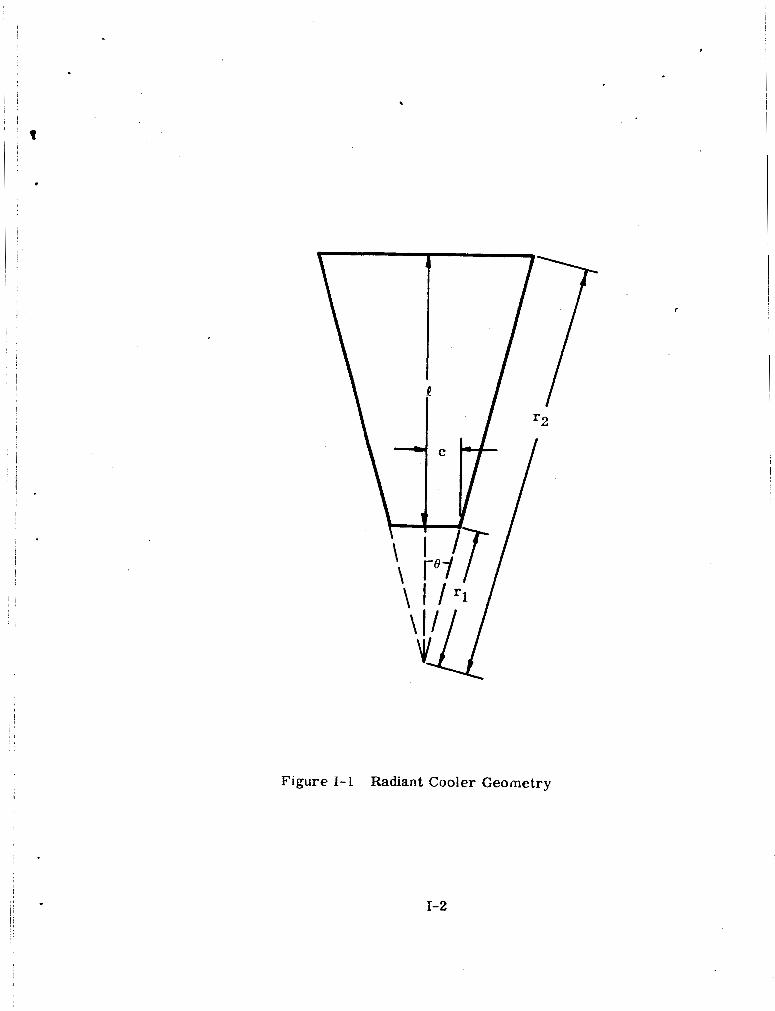
The geometry of a radiant cooler stage through a vertical or horizontal plane is shown in Figure 1-1. This may also be considered a section of a truncated right circular cooler. The cone lengthf of the stage is given by
where
r2 = distance along cone surface from apex to mouth
rl = distance along cone surface from apex to patch
e = half angle of cone
The total length of a two-stage cooler, from cone mouth to cone mouth, is 21. The half width of the patch in the plane is given by
c = r 1 s i n 8 (1-2)
And the ratio of cone length to patch half width is rl
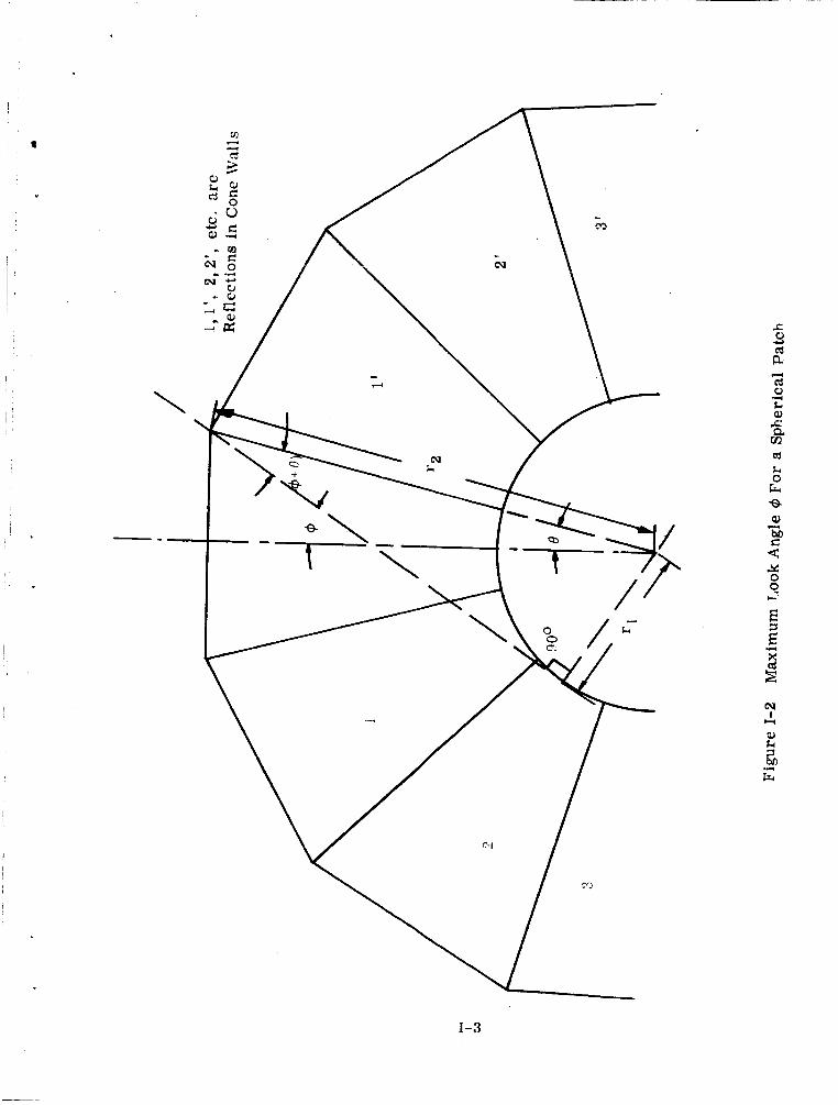
Now the maximum look angle, 9 , for a spherical patch is given by (See Figure 1-2)
(1-3)
rl '2
sin ( 9 - 6 ) = -
1-1
(1-4)
i ' i
I
.
r
Figure I- 1 Radiant Cooler Geometry
1-2
,
0 Fr
E
cu I
U
1-3
This relation is a good approximation for a flat patch when Ois small and a safe value of any 8 , since +for a flat patch is always less than or equal to @for a spherical patch in a cone of the same geometry (same Band q/r2) . The angle 9 is the maximum angle to the patch normal (axis of the cone) at which radiation from the patch leaves the cone mouth and the maximum angle to the cone axis of an external object that can be seen from the patch area. The effect of the cone is therefore to act as a crude collimator for patch radiation and as a set of blinders to an observer on the radiant patch.
*
Thus for a given maximum look angle
cot 6 1 - s in (9- 6 ) Q C sin ( +- 6 )
- - - (1-5)
The cone length to patch half width ratio for fixed Q, is then only a function of the cone half-angle 0 .
To minimize l /c, I
For small cone angles we may use the approximation cos 6 = 1, in which case (1-6) can be solved for sin 6. The result is
This formula can be used to determine a first approximation to the optimum cone half angle, which can be used as the starting value in equation (1-5) to determine a more accurate result.
Once the optimum value of the cone half angle has been calculated, the ratio rl/r2 is set by equation (1-4) for the given maximum look angle. This sets the geometry, but not the scale, of the cooler. The ratio of minimum t /c values in the horizontal and vertical planes yields the optimum aspect ratio of the radiant patch.
Plots of l /c versus 6 are given in Figure 1-3 for maximum patch look angles of 30 degrees, 31.5 degrees, 45 degrees, and 60 degrees. Note that n/c 00 as 0 - $(equation 1-5) and that the curve is broader for larger values of 9. The values of optimum 8 and minimum Q / c are given in Table 1-1 and the optimum patch aspect ratios for various combinations of vertical and horizontal look angles in Table 1-2.
1-4
,
11
11
10
9
8
7
6
5
4
3
/
350
Figure 1-3 Relative Length Versus Cone Half Angle
1-5
Table 1-1
Optimum Cone Geometry for Given Maximum Look Angle
9
300
(l/c) min Oopt
13' 10.48
45O 1 7 O 3.69
60° 1 8O 1.520'
Table 1-2
Optimum Patch Aspect Ratios for Given Maximum Look Angles
Vertical Horizontal Aspect Ratio
3 0' 6 0' 6. 89
31.5' 6 0' 6.13
450 6 0' 2.43
450 450 1.00
60° 6 0' 1.00
There are other optimizations possible in addition to the one carried out above to minimize the cone length to patch half width ratio. One would like to find an optimization procedure directly related to the thermal performance, for example. This might be accomplished by minimizing the radiative couplfng between the patch and its cone (Appendix II). The geometrical parameters which influence radiative coupling are e and 9, and for a fixed 9 the minimum occurs at 8 = $. This means rl/rz- 0 and l/c --fa, that is , either an infinitesimal patch or an infinitely long cone is required. Neither solution is practical, of course, and this approach to optimization was abandoned.
I- 6
APPENDIX 11
EMISSIVITY OF GOLD SURFACES IN SINGLE-STAGE RADIANT COOLER
Equations are derived from the effective emissivity and effective reflec- tivity of the cone structure as viewed from the patch in terms of the actual surface emissivity. These equations are then used to estimate the average
K radiant cooler from performance data using a right circular equivalent to the rectangular cone strmture. These equations are also used in Appendix III to calculate the effective patch to cone emissivity of both stages of the two-stage cooler using the maximum gold surface emissivity in the single-stage cooler and the emissivity of a good evaporated gold surface.
R l L I Z W P eBlhSiVi@ Of the gold-Cnnt& SUl'fmeS h fie Sin@e-t&Z&gea 200 &PeeR
Calculation of Effective Emissivity from Surface Emissivity
The black radiating patch in a radiant cooler views cold space via a low- emissivity, high-reflectance cone structure. If fn is the fraction of radiant flux from the patch which reaches space after n reflections from the cone walls, the effective reflectance of the cone, as seen from the patch, is
(11-1)
where pgis the reflectance of the cone surface and cg its emissivity. effective reflectance of the cone is the fraction of radiant power emitted by the patch that reaches cold space. This concept is used in the study of cavities to express the fraction of incident radiation reflected back out of the cavity (See, for example, E. W. Treuenfela, JOSA 93, 1162, 1963). In the case of the radiant cooler, the cavity is in the form of a truncated conical perforation.
The
According to Kirchhoff 's radiation law, the effective emissivity, ePc, of the cone structure, as seen from the patch, is then (1 - p ). That is, PC
= 1 - z & (1 - E g P (E-2) n = O PC
This is one of the three general methods employed for deriving equations for cavity emissivity (G. A. Rutgers, Handbuch der Physik, Bd. 26 (Springer- Verlag, Berlin, 1958), p. 129).
A n expression for the effective patch to cone emissivity may also be obtained directly with the help of Figure 11-1. ABCD is a cross-section of a radiant cooler in which BC is the black patch. BC' and CB' are images of the patch formed by one reflection in the cone walls; C'B" and B'C" are images of the patch by two reflections. The cone walls are assumed to be specularly
II-1
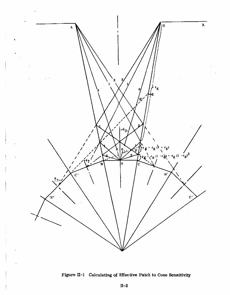
Figure II-1 Calculating of Effective Patch to Cone Sensitivity
II-2
reflecting and the patch to have an absorptance of unity. multiple-reflections shown in the sketch has been used by Sparrow and Lin to determine the emissivity of a specularly reflecting V-groove cavity ("Absorp- tion of Thermal Radiation in V-Groove Cavities", U. of EM. for NASA-Lewis, N62 10682, July 1962). It has also been employed by Williamson (JOSA 42, 712,
cone channels.
The technique of
1
1952) and Hanel (ARS Journ. 31, 246, 1961) in the study of specularly reflecting
The view of the cold space and the cone walls from the patch will be approximated by the view from the center of the patch. The Fraction, ICo, of radiation emitted by the patch between the normal to the patch and the rays 0 goes directly to space without reflection from the cone and is equal to Fps, the view factor from the patch to space (i. e. , the fraction of emitted radiation going directly to space). Rays between 0 and ray 1 are reflected once from the cone wall before going to space; rays between 1 and 2 are reflected twice and between 2 and 90 degrees to the patch normal, three times. The fraction of patch radiant flux which reaches cold space is then
ppc = fo + fl Pg + f2 Pg 2 + f 3 p g 3 + ' * - = I: n = O
fnppn (11-3 )
The radiant flux from the patch which is absorbed by the cone wall is then given by
where Tp is the patch temperature and Ap the patch radiating area. The radiant flux lrom the patch therefore either goes to cold space or is absorbed in the cone walls. None is returned to the patch because of the outward sloping, specularly reflecting walls.
I
When reversed in direction, the paths by which rays go to space via reflections from the cone walls become the paths by which radiation from the cone walls reaches the patch. W e may therefore expect that since (1 - p ) is the effective absorptance for radiation going from the patch to space, that it is also the effective emissivity for radiant transfer from the cone walls to the patch. This is shown by means of Figure II-1.
PC"
Radiation from the cone wall may reach the patch by a direct path or by reflection off the cone wall. Al l the cone wall can see the patch directly. The cone wall between D and F can see the patch by one reflection off the walls; this area is determined by the rays 1 and 1' from the image of the patch formed by one reflection. This once-reflected cone radiation may be accounted for by
due to direct coupling, to the cone wall area between 90 degrees to the patch normal and the boundary where ray 1 from the patch center first strikes the wall. The once-
I assigning an emissivity E
reflected wall radiation effectively comes from this area, since it is reflected
(1 - E g), in addition to the emissivity E I
I II-3
from the area before being absorbed by the patch. Similarly, the cone wall between D and E can see the patch by two reflections in the cone wall; this area is determined by rays 2 and 2' from the image of the patch formed by two reflections. The twice reflected radiation may be accounted for by assignhg a third emissivity component of fg (1. -eg)2 to the cone wall area between 90 degrees to the patch normal and the boundary where ray 2 from the patch center first strikes the cone wall.
v
The above procedure may be extended until a reflection m is reached such that thernth reflection of the patch in the cone wal l s cannot see the cone walls. In the attached sketch, the maximum number of wall reflections for wall emission is two, so that m is three. The radiant power transfer from the cone wall to the patch can therefore be determined by assigning an emissivity
En [l + (1 - E g ) +
to the wal l area A,, where An is the wal l area initially intercepted by rays from the patch center that require n reflections to go to cold space. The above is a geometrical progression and may 5e summed to give
En = [ 1 - (1 - E g I n 1
The radiant power transfer from the cone walls to the black patch is then
9 = (T Tc4 2 An gn [l -(1 c-P n = O
where gn is the view factor from An to the patch area Ap (i. e. , the fraction of diffuse radiation from An which goes directly to Ap). But
where fn is the view factor from the patch to area An (M. Jakob, Heat Transfer, Vol. II, Wiley and Chapman & Hall, 1957, p. 9). the fraction of patch radiation that reqdres n reflections in a perfectly reflecting cone (pg = 1) to reach cold space. Hence.
The view factor fn is equal to
n The sum over n may be rewritten I: fn - C fn (1 - eg) . But n = O n = O
f n = l n = O
II-4
(II-10)
. (Jakob, op. cit. , p. l o ) , that is , the sum of all view factors from the patch (over a hemisphere) is unity. Equation (11-9) then becomes
n 9 = UT, 4 Ap [l - z fn(1 -Eg) 1
n = O C-P (11-1 1 )
Finally, since the patch is black (absorptance of unity), no wall radiation is reflected back to the walls, and the net radiative exchange between the cone walls and the patch is (Equation I][-4 and II-11)
The effective emissivity for cone wall-patch radiant exchange is therefore
as already obtained by application of Kirchhoff's law. For E g 2 < 1
(11-13)
(11-14)
and for Eg << 2/(n-l) i.e. , E g 1 for n 5 3
(1 -egP = 1 - n eg (11-1 5)
The equation for the effective patch to cone emissivity then becomes
E = Eg c nf, n = O PC (11-16)
Average Surface Emissivity of the Single-Stage Cooler
The performance of the single-stage cooler may be expressed by its thermal balance equation
Ts = temperature of surroundings
K, = conductive transfer coefficient
Hi = radiative transfer coefficient
II-5
In the single-stage 200 degrees K radiant cooler, no more than three reflections off the cone wall a r e necessary for a ray to go from the center of the radiating patch area to cold space. Equation (11-16) for the effective cone emissivity transfer can therefore be used, and the equation for the radiative coefficient becomes
Hi = a E g [Ar 2 n f n + 1 / 2 A b ] (11-18) n = O
where
~ A, = radiating (front) patch area.
Ab = non-radiating (back) patch area plus other surfaces radiantly coupled to cylinder
= average surface emissivity
2 2 %
A, is 1.52 in and Ab, 3.04 in ; eg is the average among the cone walls, the area Ab, and the cylinder structure surrounding Ab. The equation assumes plane-parallel geometry or its equivalent between Ab and a specularly reflecting cylinder structure. From data taken during test runs on HRIR model F-3, Tp = 201 degrees K when Ts = 290 degrees K. the six chrome1 AA suspension wires is 0.278 mw/degrees K. Equation (II-17) then becomes, on substituting the values for A, and Ab and solving for Hi.
The conductive coefficient for
(65.9 -90.6 Eg 2 n fn) Hi = x 10-8 mw/(orC)4 (11- 19)
54.4
Equating this to equation (11-18), Eg can be determined if the fn are known.
The view factors fn may be estimated by the use of an equivalent truncated right circular cone in place of the actual rectangular cross-section cone. The view factor directly to space, fo, from the center of the patch can be calculated from a formula given by Jakob (op. cit. , p. 12)
arcsin 2 Fps = fo = - U
The cone length is P (Figure 1-1 in Appendix I) and the cone mouth area 2a x 2b. In the single-stage cooler, a = 1.375 inches, b = 1.75 inches, and I = 4.6 inches. From equation (11-20), fo is then equal to 0.126. In a right circular cooler
fo = sin 2 I#Jo
where # J ~ is the angle between the patch normal and ray 0 , as shown in the attached sketch. The cone height (distance from patch center to diameter AD
11-6
along normal to patch) is 4.6 inches in the single-stage cooler, so that the equivalent cooler has a radius'r = 4.6 tan r+40 = 1.74 inches at the opening AD. The angles law of cosines, which yield the equation
(Figure 11-1) can be determined by means of the law of sines and *
r2 sin [(2 n + 1) 8 J sin & = (11-21)
[r22 + r12 cos 2 e -2r1 cos er2 cos (<2 n + i > e ) ~ ' ' ~
where
e = cone half angle
rl = distance along cone surface from apex to patch
r2 = distance along cone surface from apex to mouth
The geometry of the cooler is shown in Figure 1-1 in Appendix I. For a given maximum patch look angle $ (equation 1-4 in Appendix I), this may be written
As in Appendix I, we wil l assume that the patch area is concentrated at its center, i. e. , that the view factors from the center of the patch equal the values averaged over the patch area. For a truncated right circular cone in which rays at angles between #n -1 and $, to the patch normal require n reflections to reach cold space, the view factor is given by
(11-23) $ = l/r i" sin 6cos 6,dadcp = sin 2 & -sin 2 $n-l
Ps= 0 9 = $n-1
The integral is written in terms of spherical coordinates at the patch center with the pole along the patch normal; 6 is the pole angle and 'p the azimuthal angle. From equations (11-13), (11-22), and (11-23) we see that the effective patch-to- cone emissivity for a given maximum look angle depends only on the emissivity of the gold-coated surfaces and the half angle of the cone.
For the equivalent right circular single-stage cooler, equation (II-21) yields
$2 = 82O 45'
Rays from the patch center at angles to the normal between $o and $1 require one reflection to go to space, those between $1 and 92, two reflections, and
II-7
I those between #2 and 90 degrees, three reflections, The fn for the right circular I equivalent of the single-stage cooler are then
fo = = 0.126
2 2 f1 = sin q1 - sin q0 = 0.570
2 2 f2 = sin $2 - sin qb1 = 0.291
2 1 - sin $2 = 0.013
I -
f3 -
l and
(11-24)
(11-25)
From equations (11-17) and (11-19) the average surface emissivity of the 200 degrees K cooler is ,
cg = 0.086 (11-26)
The back area of the patch assembly and cylinder surface contain holes, con- necting wires, and surface cavities. The surface emissivity of the cone walls is therefore lower than the average. For this reason, use of the above value to estimate the performance of the two-stage cooler, in which the patch radiates to space from both sides and the cylinder is eliminated, yields upper limits for the patch temperature (i. e. , minimum performance values).
Now the radiation exchange is a minimum for specular reflection at the enclosing surface for close-spaced, coaxial, or concentric geometry (M. Jakob, "Heat Transfer", Vol. II, Wiley and Chapman and Hall, 1957, p. 49). Such a geometry is assumed in equation (11-17) and thus in the result (11-26). We may therefore conclude that the average gold surface emissivity in the single-stage cooler is less than 0.086. A lower limit is obtained by assuming the cylinder to be effectively black. The radiative transfer coefficient then becomes
(11-27)
And the average gold surface emissivity (cone and back of patch) is reduced to cg = 0.062.
II-8
APPENDIX III
EFFECTIVE PATCH To CONE EMISSMTIES IN TWO-STAGE COOLER
The general technique of calculating the effective patch to cone emissivity for truncated right circular cones usmg the method of multiple reflections is described in Appendix II. From equation (11-13) in that Appendix, the effective patch to cone emissivity of the second stage for a truncated right circular cone is
where
p g ) =
=
effective reflectivity of cone for patch radiation
true surface emissivity of gold-coated cone g
E
1 - E = true surface reflectivity of cone g
fn = view factor from patch to cone wall area initially intercepted by rays from the patch that require n cone reflections to go to cold space
The view factor fn is also equal to the fraction of emitted patch radiation that requires n reflections in a perfectly reflecting cone to go to cold space.
The angle #n can be determined by means of the multiple reflections shown in Figures III-1 and III-2. Thus rays from the patch center at polar angles between q1 and $2 require two reflections at the cone to go out the cone mouth. Stated another way, an observer at the patch center looking out at angles to the patch normal between $1 and $9 sees cold space by two reflections in the cone walls. The angle #n in a truncated right circular cone is given by equation (11-21) in Appendix II, which is
r2 sin [(an+ 1) 6 1 (m-3 1 sinen =
[r22 + r12 cos2 e -211 cos e r2 cos + I >
where
8 = hJf-angle of cone
rl = distance from cone apex :along cone surface to patch
= distance from cone q e x along cone surface to mouth r2
111-1
cu 0
4
U U H
I
111-2
111-3
Figures ID-1 cones having
and III-2 show the multiple reflections of truncate? right circular the geometry of the vertical plane and horizontal plane, respectively
of the second stage of the two-stage cooler. These geometries have been used in place of the equivalent right circular cone employed in Appendix I because of the large aspect ratio of the patches in the two-stage cooler.
The values of sin en were calculated for the vertical and horizontal geometries using equation (m-3). from equation (III-2). The resultr, are given in Tables m-1 and 111-2. Note eat io = sinu q0.
The view factors fn were then determined
9
Table m-1
View Factors for Vertical Geometry of Second Stage
n
0
f n = sin 2 $n -sin 2 $n -1 sin #n
0.212 0.045
1 0.589 0.302
2 0.049 0.373
0.978 0.236 3
4 1 0.044
Table III-2
View Factors for Horizontal Geometry of Second Stage
n sin +jn 2 2 f n = sin Z # J ~ -sin
0 0. 556 0.309
1 0.968 0.662
2 1 0.029
The sum of all view factors C fn is unity for a given geometry according to the definition of view factor (M. Jakob, "Heat Transfer", Vol. II, Wiley and Chapman and Hall, 1957, p. 10).
The values of partial reflectivities, fn (1 - E ~ ) ~ , are listed in Table III-3 for Eg equal to 0.02 and 0.086.
m-4
. Table III-3
Partial Patch to Cone Reflectivities for Second Stage
Vertical Horizontal n Eg 0.02 0.086 0.02 0.086
0 0.045 0.045 0.309 0.309
1 0.296 0.276 0.605 0.649
2 0.358 0.312 0.024 0.028
3 0.222 0.180
4 0.041 0.031
By adding the partial reflectivities and subtracting the sum from unity, we obtain the effective patch to cone emissivity according to equation (III-1). The results are given in Table III-4.
Table m-4
Effective Patch to Cone Emissivity for Second Stage
Vertical Horizontal Average
0. 02 0.038 0.014 0.026
0.086 0.156 0.062 0.109
The effective patch to cone emissivity for the first stage was also determined using the above procedure. The results are shown in Table ID-5 for gold surface emissivities of 0.02 and 0.086.
Table III-5
Effective Patch to Cone Emissivity for First Stage
Vertical Horizontal Average g E
0.02 0.024 0.010 0. 017
0.086 0.103 0. 044 0. 0735
m-5
APPENDIX IV
EXTERNAL THERMAL LOAD ON FIRST STAGE (SECOND-STAGE CONE)
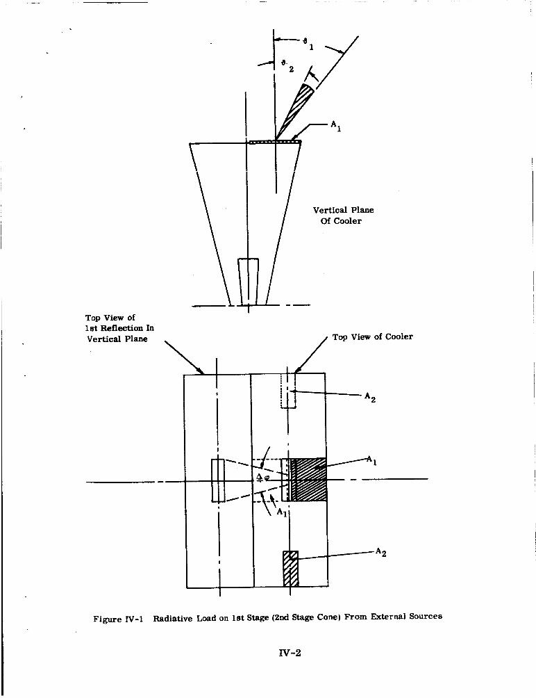
The radiative coupling between the modified second-stage cone and the external sources may be estimated by means of the vertical-and horizontal-plane ray traces described in Section 2.2. As seen by the second-stage cone, the sxtenid sources may be considered to lie in the plane of the mouth of the first- stage cone and to consist of four areas, designed by A1 and A2 in Figure IV-1. Each area extends 3.8 inches* from the mouth edge and is as wide as the mouth of the second-stage cone.
The radiant emittance (watts/cm2 emitted) of the second-stage cone is much less than that of the external sources, so that the thermal load on the first stage from an external source is very nearly
where
Ac2 = outside area of the second-stage cone
= view factor from the second-stage cone to the external source (as seen by reflection)
Fc2-x
Wx = radiant emittance of the external source
(Y = absorption factor for external radiation incident on X the second-stage cone
However, we have for diffuse emitters (M. Jakob, "Heat Transfer", Volume 11, Wiley, 1957, p. 9)
AC2 Fc2-x
where
= view factor from AI to the second-stage cone FA1-C2
FA2-c2 = view factor from A2 to the second-stage cone
*Estimated by means of a scale drawing
IV-1
Top View of let Reflection In Vertical Plane
r- r- I
' / Vertical Plane
Of Cooler
Top View of Cooler
Figure N-1 Radiative Load on 1st Stage (2nd Stage Cone) From External Sources
w-2
The average view factors may be estimated from the following equation (see Jakob, op, cit., eq. (31-17)
The factor 1/2 assumes the average value of maximum. The maximum value is at the edg~ of the cone mouth and is determined by the maximum g range, g1 to g2. The quantity sin g dgdq is an element of solid angle in spherical coordinates (& cos & dA2 in Jakobgs notation) centered on Ai, as shown in Figure IV-1. The factor cos 6 (cos (4 in Jakob's notation) accounts for the diffuse nature of the radiation and 3 normalizes the view factor to a maximum value of unity. The view factor from one surface to another is unity when all rays emitted by the first surface strike the second surface. Inte- grating (IV-3).
cos g sin 3 dg is one-half the
= 2 [sin2 d2 - sin2 FAi-C2 4r w-4)
In the vertical plane, 92 = 43 degrees and +1 = 31.5 degrees; in the hori- zontal plane, g2 = 65 degrees and a1 = 60 degrees. The an* range A q is set by the first reflection of the second-stage cone in the first-stage cone. A s seen along the patch normal, it is the angle subtended at the center of Ai by the side of the second-stage cone Once reflected in the first-stage cone. Equation (IV-3) assumes that the limiting g values are the same throughout Aq. In addition, the absorption at the second-stage cone is less for rays out of the horizontal and ver- tical planes. To account for these effects, we will assume that the areas at the mouth of the first-stage cone are limited in their widths to the dimensions at the mouth of the second-stage cone (see Figure IV-I) and that the absorption factors at the second-stage cone are constant in Atp and equal to the average value in the 6 range. Note that the top view of the first reflection in the vertical plane shown in Figure IV-1 is shortened in the vertical direction by cos (2 x 13.5 degrees) = 0.891.
In the vertical plane, Aq = 28 degrees = 0.49 radian. This value was obtained using the dimensions and angles of the first-stage design and the dimen- sions of the modified (final) second-stage cone, qection 2.1). Thus,
= 7 . 5 ~ 10-3 FA1-C2
And in the horizontal plane, Aq = 3 degrees = 5.2 x radian, and
= 3 x 1 0 4 FA2-C2
Radiative coupling between the second-stage and external sources is therefore much weaker in the horizontal direction than in the vertical direction.
Iv-3
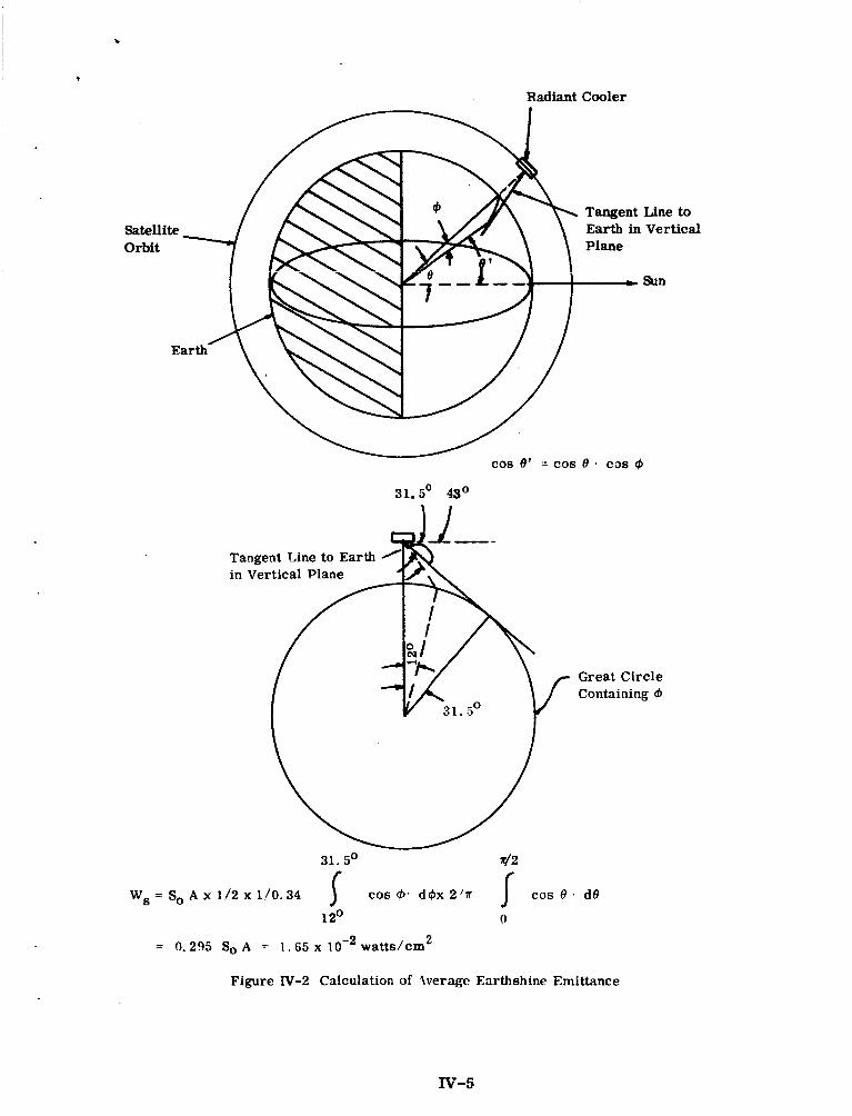
We will assume that the second-stage cone sees the two A2 (horizontal direction) areas as blackbodies at the maximum radiometer base temperature of 35 degrees C. The emittance of these external sources is therefore wb = 5.1 x loe2 watts/cm2. The A1 (vertical direction) area nearest the spacecraft is seen at the same temperature, while the other A1 passes infrared emission and reflected sunlight from the earth. The sunlight reflected from the earth (earth- shine) will be expressed as an average equivalent source emittance for a sun- synchronous, polar orbiting earth-oriented spacecraft. Because the thermal time constant of the first stage is very long, at least the order of the time it takes the spacecraft to orbit the earth (Appendix V), only the earthshine value averaged over a spacecraft period is needed. l
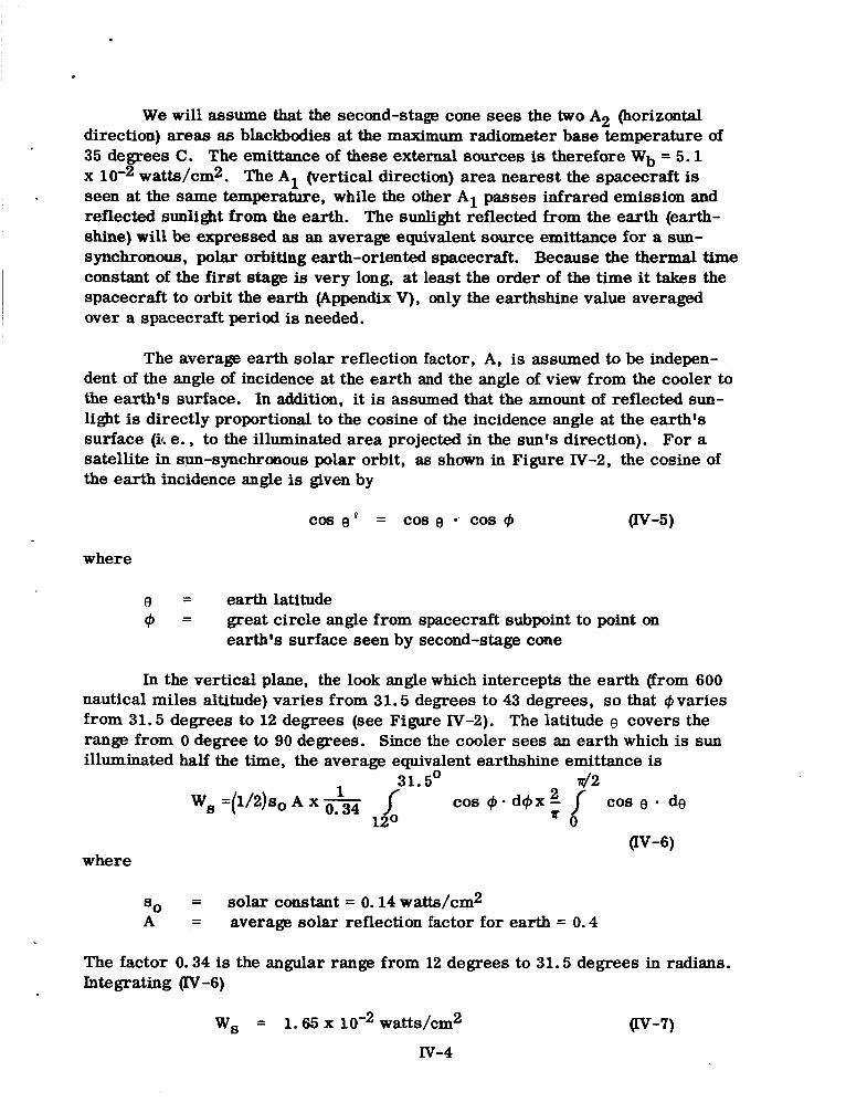
The average earth solar reflection factor, A, is assumed to be indepen- dent of the angle of incidence at the earth and the angle of view from the cooler to the earth's surface. In addition, it is assumed that the amount of reflected sun- light is directly proportional to the cosine of the incidence angle at the earth's surface (i4. e., to the illuminated area projected in the sun's direction). For a satellite in sun-synchronous polar orbit, as s h a m in Figure IV-2, the cosine of the earth incidence angle is given by
cos$ = cos e cos Q v - 5 )
where
0 = earth latitude Q = great circle angle from spacecraft subpoint to point on
earth's surface seen by second-stage cone
In the vertical plane, the look angle which intercepts the earth (from 600 nautical miles altitude) varies from 31.5 degrees to 43 degrees, so that 4 varies from 31.5 degrees to 12 degrees (see Figure N-2). The latitude 0 covers the range from 0 degree to 90 degrees. Since the cooler sees an earth which is sun illuminated half the time, the average equivalent earthshine emittance is
31.5' d2 Ws =(1/2)s0 A x f cos d Q x 2 f cos e de
120 " 0 (N-6)
where
so = solar constant = 0.14 watts/cm2 A = average solar reflection factor for earth = 0.4
The factor 0.34 is the angular range from 12 degrees to 31.5 degrees in radians. Integrating (N-6)
W, = 1. G x 10-2 watts/cm2
N-4 Qv-7)
Radiant Cooler
Tangent Line to Earth in Vertical
COS e' = COS e . COS Q
31.5' d 2
Great Circ le Containing $I
W, = So A x 1/2 x 110.34 COS $- d @x 2 'ir COS 8 . d0
12O 0
2 = 0.295 So A = 1.65 x watts/cm
Figure IV-2 Calculation of Iverage Earthshine Emittance
The solar radiation not reflected by the earth is absorbed by it and radiated to space at infrared wavelengths. The average infrared emittance of the earth, We, is therefore determined by
4r ~ ' 2 we = ~ ' 2 so (1 -A) v-8) -2 We = (1/4)s0 (1 - A) = 2.1 x 10 watts/cm2
I where R' is the earth's radius. If the earth were a uniform blackbody in the infrared as seen from space (which it is not), its temperature would be 247 de- grees K.
Next, we need to know the second-stage cone absorption factors for earth- shine and infrared radiation. The solar absorption factor, a , for a single reflec-
by C. W. Allen C'Astrophysical Quantitiesff, U. of Lon., The Athlone Press, 1963, p. 104) and the spectral irradiance of the sun's rays outside the earth's atmosphere given in the "Handbook of Geophysics" (USAF, Macmillan, 1960, Chapt. 16). The result was a r 0.22 or a solar reflectance of 0.78. We will assume that the infrared emissivity (absorptivity) of the gold surface equals the average value of the gold surfaces in the single-stage, 200 degrees K radiant cooler (0.086). If the radiation is reflected between the first-stage cone and the second-stage cone with five reflections at the second-stage cone, the absorption factor is
tion from a gold surface was calculated using the spectral re a ection of gold given
g
where R = 1 -a is the reflectivity. In the vertical plane, the maximum number of second-stadcone reflections is five, so the maximum absorption factor is 0.40 for earthshine and 0.362 for infrared radiation. The minimum absorption factors (agR) are 0.172 and 0.079, respectively. Since the external radiation at 31.5 degrees passing through A1 undergoes from 5 to 1 reflections at the second- stage cone, the average absorption factors at this angle are 0.287 for earthshine and 0.181 for infrared. Rays at 43 degrees through A1 undergo only one reflection at the second-stage cone. The average absorption factors in the vertical plane for all rays through A1 are then infrared. In the horizontal plane, the average infrared absorption factor is
= 0.23 for earthshine and (Yir,v = 0.13 for
air, h = 0.095.
Using the facts that A1 = 3.8 x 4.5 in2 = 110 cm2 and A2 = 3.8 x 1.5 in2 = 36.7 cm2, we are finally in a position to calculate the thermal load on the first stage (second-stap cone) produced by external sources at angles beyond the max- imum look angles of the first-stage patch.
IV-6
~
I I The result is I
' . z@x-c2 = 2 F A 1 4 2 P i r , v w b + We) + " s , v w s ~ +
2A2 FA2-C2 "ir, h wd %-c2 = 22 milliwatts P-10)
~
The factor 2 in front accounts for the double-ended cone structure. The first stage radiates about 300 milliwatts at a temperature of 105 degrees K. The above load increases this by 7 .3 percent and therefore increases the patch temperature by about .+ percent or 1 . 9 degrees K.
I
Iv-7
APPENDIX V
THERMAL TIME CONSTANT OF OUTER CONE FACING
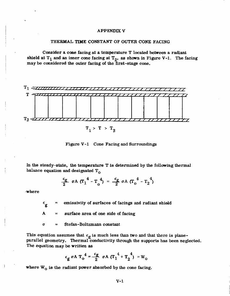
Consider a cone facing at a temperature T located between a radiant shield at T1 and an inner cone facing at T2, as s h m in Figure V-1. The facing may be considered the outer facing of the first-stage cone.
T
T2
Figure V-1 Cone Facing and Surroundings
In the steady-state, the temperature T is determined by the following thermal balance equation and designated To
%oA(T:-T:) = + c r A ( T o 4 - T 2 ) 4 2
:where
E = emissivity of surfaces of facings and radiant shield
A = surface area of one side of facing
g
U = Stefan-Boltzmann constant
This equation assumes that eg is much less than two and that there is plane- parallel geometry. Thermal conductivity through the supports has been neglected. The equation may be written as
where Wo is the radiant power absorbed by the cone facing.
v-1
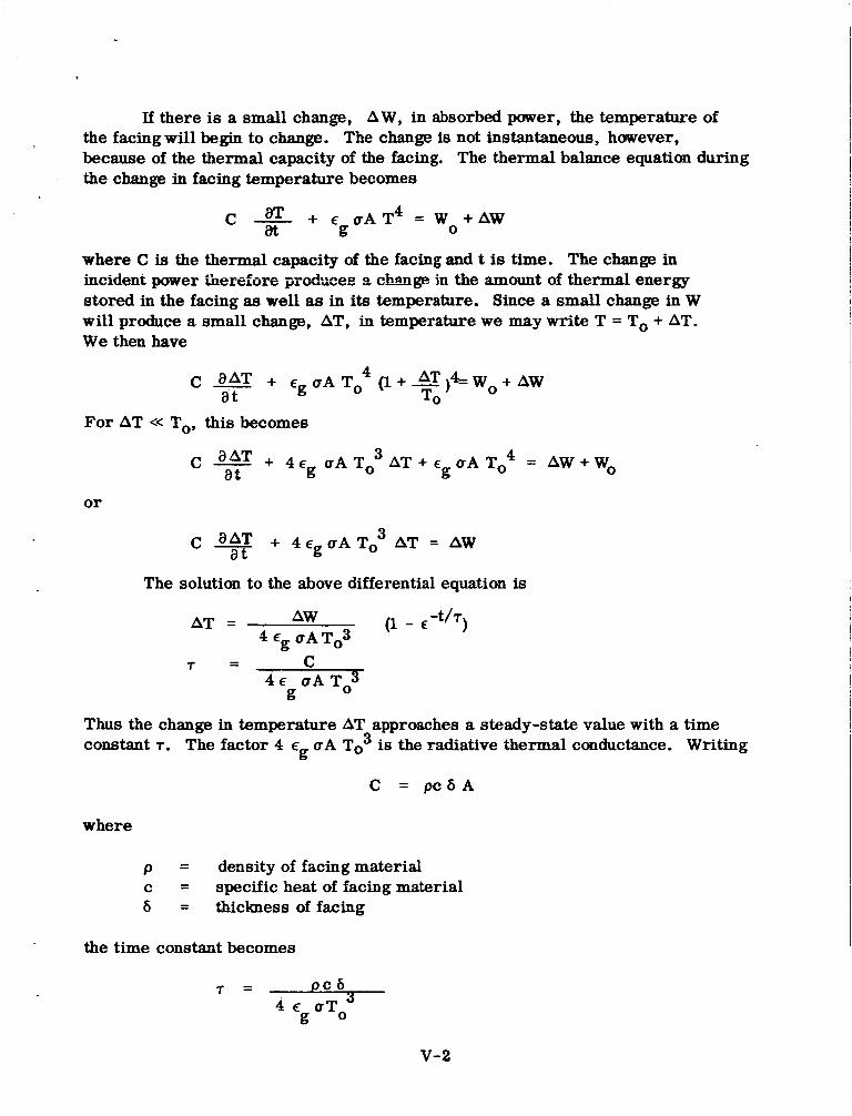
If there is a small change, AW, in absorbed power, the temperature of the facing will begin to change. The change is not instantaneous, however, because of the thermal capacity of the facing. The thermal balance equation during the change in facing temperature becomes
I -
where C is the thermal capacity of the facing and t is time. The change in incident power ihere~u~G - -- -=--- ---&-no= pLrvuuuuu I 9 nhan -.-- e ~ ! in the amount of thermal energy stored in the facing as well as in its temperature. Since a small change in W will produce a small change, AT, in temperature we may wri te T = To + AT. We then have
For AT << To, this becomes
or
c + 4 E g u ~ ~ 0 3 AT = AW a t
The solution to the above differential equation is
AW (I-€ -th) AT = 4EgoATo3
Thus the change in temperature AT approaches a steady-state value with a time constant T. The factor 4 E o A To3 is the radiative thermal conductance. Writing g
C = p c 6 A
where
p = density of facing material c = specific heat of facing material 6 = thickness of facing
the time constant becomes
V-2
I For an aluminum facing at -50 degrees C = 223 degrees K,
c = .8 0 joules/gm degrees C p = 2.7 gms/cm3
For 6 = 2.5 x 10a inch = 6.35 x 10-C)rcm and E = 0.1, 7 = 5.45 x 10³ seconds = 1.51 hours. g
Tne thermal time constant of the cone facing is therefore the order of the time it takes the spacecraft to orbit the earth. The thermal lag of the cone facing and other structures smooths out the variations in power absorbed at the outer surface of the radiant cooler. Absorbed power averaged over a spacecraft orbit can therefore be used to determine the effect of outer surface thermal load on radiant cooler operation.
v-3
APPENDIX VI
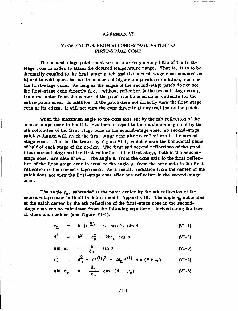
VIEW FACTOR FROM SECONDSTAGE PATCH TO FIRSTSTAGE CONE
The second-stage patch must see none or only a very little of the first- stage cone in order to attain the desired temperature range. That is, it is to be thermally coupled to the first-staw patch (and the second-stage cone mounted on it) and to cold space but not to sources of higher temperature radiation, such as the first-stage cone. As long as the edges of the second-stage patch do not see the first-stage cone directly (i. e. , without reflection 5x1 the second-stage cone), the view factor from the center of the patch can be used as an estimate for the entire patch area. In addition, if the patch does not directly view the first-stage cone at its edges, it will not view the cone directly at any position on the patch.
When the maximum angle to the cone axis set by the nth reflection of the second-stage cone in itself is less than or equal to the maximum angle set by the nth reflection of the first-stage cone in the second-stage cone, no second-stage patch radiation will reach the first-stage cone after n reflections in the second- stage cone. This is illustrated by Figure VI-1, which shows the horizontal plane of half of each stage of the cooler. The first and second reflections of the @nod- ified) second stage and the first reflection of the first stage, both in the second- s t a s cone, are also shown. The angle q, from the cone axis to the first reflec- tion of the first-stage cone is equal to the angle #, from the cone axis to the first reflection of the second-stage cone. As a result, radiation from the center of the patch does not view the first-stage cone after one reflection in the second-stage cone.
The angle &, subtended at the patch center by the nth reflection of the second-stage cone in itself is determined in Appendix III. The angle% subtended at the patch center by the nth reflection of the first-stage cone in the second- stage cone can be calculated from the follming equations, derived using the laws of sines and cosines (see Figure VI-1).
VI-1
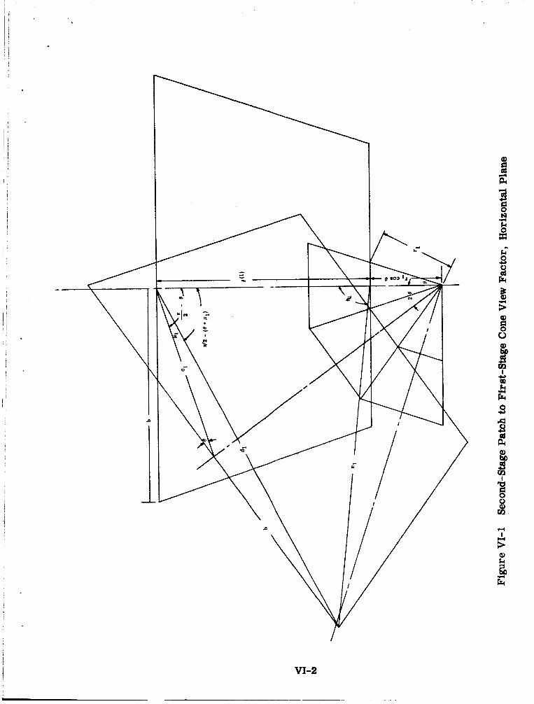
i VI-2
0
4 Y
Y k
where
1 - P (l) = cone length of first stage
= distance along cone from apex to patch in second stage 1 r
e = half angle of second-stage cone
Knowing and qn, the view factor from the center of the second-stage I patch to the nth second-stage reflection of the first-stage cone is, in a truncated
right circular cone
2 2 F @) = sin $ - sin qn P2-1 n (VI-6)
If & is less than or equal to %, the view factor is zero. The complete view factor is then
(VI-7)
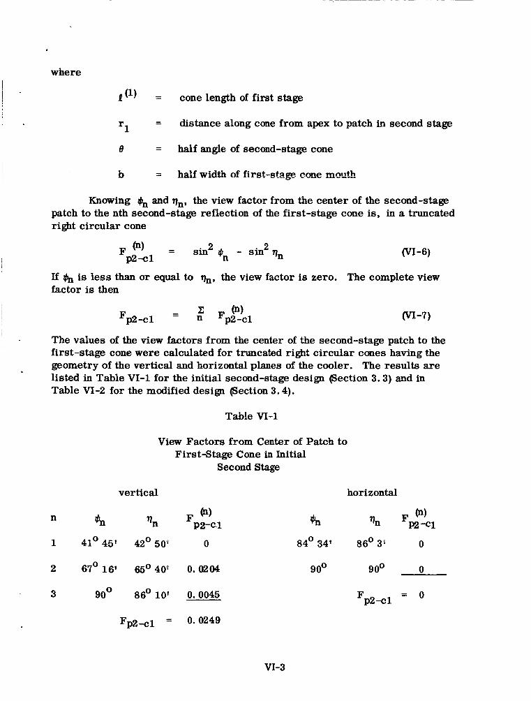
The values of the view factors from the center of the second-stage patch to the first-stage cone were calculated for truncated right circular cones having the geometry of the vertical and horizontal planes of the cooler. The results are listed in Table VI-1 for the initial second-stage design @Section 3.3) and in Table VI-2 for the modified design (Section 3.4).
I .
Table VI-1
View Factors from Center of Patch to
Second Stage Firstatage Cone in Initial
vertical
1 41' 45' 42' 50' 0
2 67' 16' 65' 40F 0. M04
3 goo 86O10' 0.0045
horizontal
84' 34' 86' 3E 0
goo goo 0
Fp2-cl = o
Fp2-cl = 0.0249
VI-3
n h
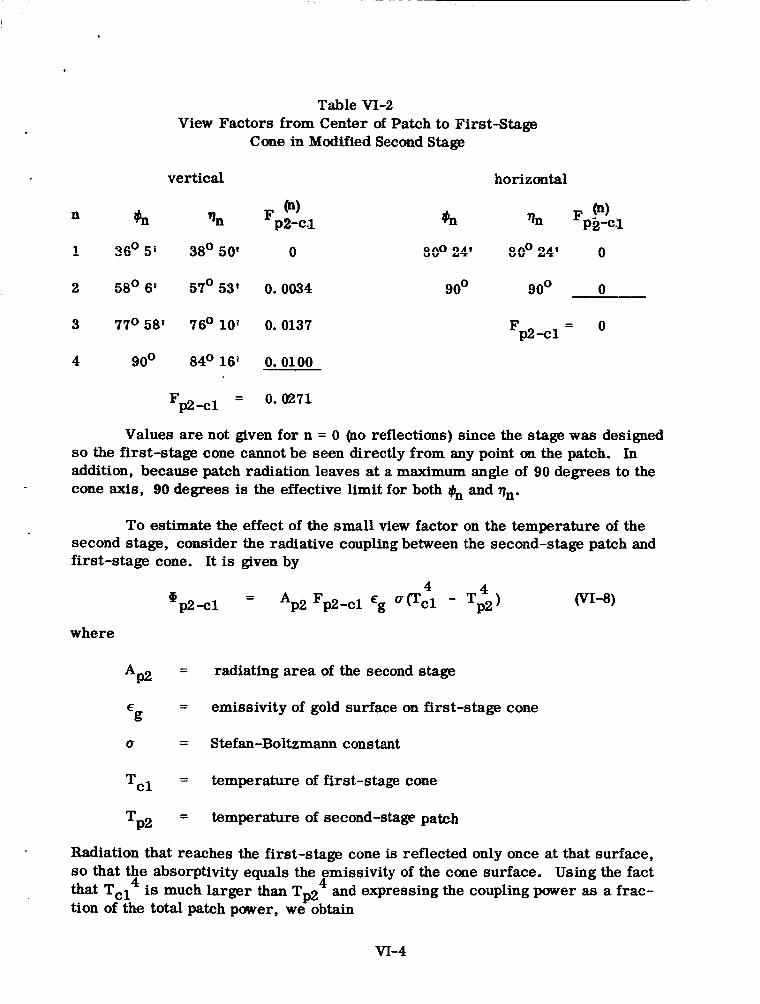
Table VI-2 View Factors from Center of Patch to FirstStage
Cone in Modified Second Stage
vertical horizontal
F @) p2-c.1
2 58'6l 57'53' 0.0034 goo goo 0
3 77O 58? 76O l o p 0.0137 Fp2-cl = o
4 90° 84' 16O 0.0100
= 0.0271 Fp2 -cl
Values are not given for n = 0 (no reflections) since the stage was designed so the first-stage cone cannot be seen directly from any point on the patch. In addition, because patch radiation leaves at a maximum angle of 90 degrees to the cone axis, 90 degrees is the effective limit for both & and qn.
To estimate the effect of the small view factor on the temperature of the second stage, consider the radiative coupling between the second-stage patch and first-stage cone. It is given by
where
AP2
g E
(T
Tcl
TP2
- 4 4 @p2-Cl - Ap2 Fp2-cl Eg VVcl - Tp2)
=
=
= Stefan-Boltzmann constant
= temperature of first-stage cone
= temperature of second-stage patch
radiating area of the second stage
emissivity of gold surface on first-stage c
(VI-8)
!one
Radiation that reaches the first-stage cone is reflected only once at that surface, so that the absorptivity equals the emissivity of the cone surface. Using the fact that TCl4 is much larger than Tpz4 and expressing the coupling power as a frac- tion of the total patch power, we obtain
VI-4
For cg = 0.086 (Apwndix II), TC1 = 199 degrees K with the earth shield in place gection 4.3). Using the average view factor for the vertical and horizontal planes (0.01355) and Tp2 = 77 degrees K,
Hp2-cl = 7.8 x
@ P2 (VI-10)
This would increase the patch temperature by about 2 percent or 1.5 degrees K. For eg = 0.02, Tcl = 248 degree8 IC gectioa 4. Z), and €or Tp2 = 67 Gsgrse:: K, the temperature increase is 0.6 degree K.
VI-5
APPENDIX VI1
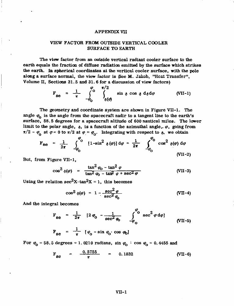
VIEW FACTOR FROM OUTSIDE VERTICAL COOLER SURFACETOEARTH
The view factor from an outside vertical radiant cooler surface to the earth equals the fraction of diffuse radiation emitted by the surface which strikes the earth. In spherical coordinates at the vertical cooler surface, with the pole dong a surface normai, the view factor ie @e 14. J&ab, Tkzt Trun~fer'~, Volume II, Sections 31.5 and 31.6 for a discussion of view factors)
r / 2 ein 3 cos g dgdrp WI-1) - 1
Fse - - A
The geometry and coordinate system are shown in Figure VII-1. The angle rpo is the angle from the spacecraft nadir to a tangent line to the earth's surface, 58.5 degrees for a spacecraft altitude of 600 nautical miles. The l w e r limit to the polar angle, g, is a function of the azimuthal angle,. rp, going from 1r/2 - rpo at 'p = 0 to 1/2 at cp = qo. Integrating with respect to 6, we obtain
But, from Figure VU-1,
using the relation sech-tanZX = 1, this becomes
2 cos219(rp) = 1 :-=&
And the integral becomes
(vn-4)
- 1 1 sec2rpdrp] (vu-5)
Fse - - 2r 1 2 q b ~ - secz% -90
1 [Po - sin q)' Fse - I
- -
For cpo = 58.5 degrees = 1.0210 radians,
cos %I
Sin 'po COS cpo = 0.4455 and
0.1832 w-6)
VII-1
GT \ Normal to S
\ JTaogent Line to Earth / -coo,
7 2,L_.2 . L 2 A
Lines to Earth From S
tan2 @o-tan 2 (D 2 2
cos2 .n= tan' Q~ -tan @+sec (z
Figure VII-I. Geometry and Coordinate System VII-2
i I
I APPENDIX MI
EFFECTIVE CONE EXTERNAL EMBSMTY
The cone views the external environment by way of ita mouth. Thus, from the point of view of the cone, the external environment may be replaced by an equivalent area stretched tightly over the cone mouth. In a manner similar to that used to derive the expression for radiant p e r transfer from the cone walls to the black patch (equation II-7 in Appenciix iij, m e m y 4erive the radiant transfer from the cone walls to the cone mouth (external environment). The result is
eqwtim fer
where
u = Stefan-Boltzmann constant
Tc = absolute temperature of the cone
E = true surface emissivity of the cone g
4 = view factor from A 1: to the cone mouth area A
h' is the cone wall area last intercepted by rays from the cone that require n-1 reflections at the cone wall to go out the cone mouth. Figure vI13-1 shows the A i areas for the vertical section of the first-stage cone and for rays which exit through the center of the cone mouth. Note that A; and AH are divided into sec- tions separated on the cone surface.
But (M. Jakob, "Heat Transfer" Volume II, Wiley, 1957, p. 9)
where f i is the view factor from the cone mouth to the area Ai. The view factor $' is also equal to the fraction of radiation entering the mouth of a perfectly reflecting cone that requtres n cone reflections to go back out the cone mouth or to the black patch at the other end of the truncated cone. Substituting (MI-2) into m-1)
vm-1
But (M. Jakob, op. cit., p. 10)
2%' = 1 n=O
- That is, all radiation which enters the cone mouth is reflected either to the patch (including the case of zero reflections) or back out the mouth in a perfectly re- flecting cone. Or, in terms of the view factor, all radiation entering the mouth initially strikes either the cone wall or the black patch (for which n = 0 and 1-4- E ;n tu g "I'
Combining (VIII-3) and (WII+I), the equation for the radiant flux emitted to the outside by the cone becomes
where p = 1- E is the surface reflectivity of the cone. This may be written g g
(VIII-6) = uTc 4 A, ( 1 - b ) @ c-m
where pmx is the effective or cavity reflectivity for radiation entering the cone mouth and equals the fraction of radiation incident on the mouth that is reflected back out the mouth and goes to the patch directly or by reflection. That is, it is the fraction entering that goes out both ends of the truncated cone cavity.. The factor 1 -pmx is the effective emissivity or absorptivity, h, as generally applied to cavities.
One may then define an effective cone external emissivity by the equation
(VIII-7) 4 'c-m = UT, Am cIIyS = CTT:AC eCX
' where Ac = Z A, is the cone wall area.
Or
n=l
(vIII-8) - Am - - - Am [l- c < (1-Egf7 EmX Ac n=O ECX - - AC
The cone external emissivity, E,,,, is equal to the absorptivity of the cone walls for incident diffuse radiation (i. e., a source stretched tightly across the cone mouth), according to Kirchhoff's laws of radiation.
VIII-3
APPENDIX M
EFFECTIVE CONE MOUTH ABSORPTIVITY FOR EARTH RADIATION
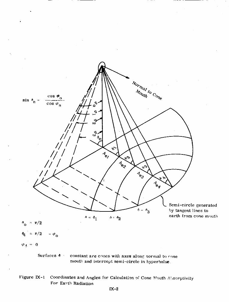
The view to earth from the mouth of the cone is the same as its view to a vertical semicircle whose radius subtends an angle equal to the angle from the spacecraft nadir to a tangent line to the earth and whose center lies on the nadir gee Appendix \?Ij. If we set cp spherical coordinates at the cone mouth, with the pole along a normal to the mouth, the number of reflections earth radiation undergoes at the cone walls before going back out the cone mouth is a step-wise function of the polar angle 6 pee Figure M-1) for a right circular cooler cone. That is, the range of polar angles can be divided into regions in which the absorp- tivity in the cone walls is a constant. Alternatively, the surface area of the earth seen from the cone mouth, or the equivalent area of the semicircle, can be divided into sub-areas, A,, whose radiation is reflected n times at the cone walls upon entering the cone mouth. The effective absorptivity of the cone mouth for earth radiation is then
where the view factor from the cone mouth to the subarea Aen.
is the absorptivity produced by n cone-wall reflections and Fm-Aen is
For the spherical coordinate system shown in Figure M-1, the view fac- tor is given by
Integrating the first term fully and the second term with respect to the polar angle, the view factor becomes
But, from Appendix VI1
seci cp sin2 q(q) = sec cpo
and
m-3)
(zx-4)
IX-1
?
sin
generated nes to
earth from cone mouth 19 = 61 19 1 792
Surfiices 6 - cons-mt are cones with a x e s alont: norrrial to r*r)ne moutl! and intercept semi-circle in hyperbolae.
Figure E-1 Coordinates and Angles for Calculation or Cone Vnouth A'mx-ptivity For Earth Radiation
M-2
Thus
I Combining equations QX-1) and @X-5), we obtain
where p + 1 is the maximum number of cone-wall reflections. For the special case p = 0 (i.e., a maximum of one reflection),
where al is the absorptivity for a single cone reflection and Fme is the view fac- tor from the cone mouth (an outside vertical cooler surface) to the earth gee
I Appendix VII).
APPENDIX X
TEMPERATURE OF COMBINED CONE AND OUTER SURFACE
For sufficiently low values (0.04 or less) of gold emissivity, the first-stage cone is to be thermally tied to the outer surface of the cooler. In this case the cone absorbs a net radiant power that is a very small fraction of the p e r radiated by the outer surface. The combined cone and outer surface then assume the temper- ature of the outer surface when it is not t l i e d l y tie:! +& &e cme.
Using the notation in Section 4.2, the net power absorbed per unit area of the first-stage cone is (for Tp14 much less than Tc4)
A* c Ws + E c e We Ac - ace
- -
4 - [Ecx + €cp (1 + 1/2 - )] UT, APl
For (See Table 5, Section 4.2.2)
= 0.02 g
€
= 0.183 g a
Tc = 248OK
Ac2 - 1/2 - - 0.492 APl
We obtain
- - A*' - 1.96 x 10⁻⁴ watts/cm2 Ac
The net radiant power absorbed by the cone adds a term
APc = 1.03 x watts/cm2 AC A3 €2
F-2)
(x-3)
for Ac/A3 = 4.75 and E = 0.9 to the right side equation (10) in Section 4.1. The net radiant power abso&ed by the cone is therefore equivalent to increasing the radiant emittance of the outer surface by
= 2.28 x 10⁻⁴ watts/cm2 F-4) 4 - 1 . 0 3 ~ 10-3 AUT, - 4.51
This is about 1 percent of UT: and would increase Ts by about 1/4 percent or 0.7 degree K, which is much less than the uncertainty in temperature of the outer surface. When the first-stag? cone is thermally connected to the outer surface, it therefore assumes the temperature of the outer surface.
x-1
APPENDIX XI
CONE MOUTH TO EARTH VIEW FACTORS WITH EARTH SHIELD IN PLACE
The view factors from the cone mouth to the earth in the absence of an earth shield are determined in Appendix IX. The surface area of the earth, or its equivalent semicircle, was divided into sub-areas, A,, whose radiation is refieciRci n times ‘iii tiis c w . ‘l%e absorptivity. %, is then constant for radiation from a given sub-area, and the effective absorptivity of the cone mouth for radia- tion from the entire surface area of the earth is given by
where F,-Aen is the view factor from the cone mouth to the sub-area A,.
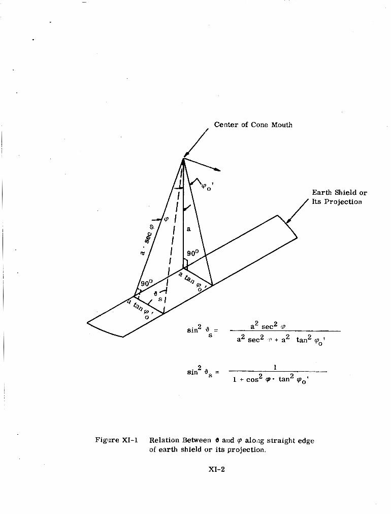
The earth shield s h m in Figure XI-1 was designed to block all radiation to the cone mouth from the sub-area A1 and part of the radiation from A2. No radiation from A3 and A4 is blocked, This is shown in Figure XI-1 by the shadow cast unto the semicircle (equivalent earth) by the shield from the center of the cone mouth, With the shield in place the view factor for n = 1 is therefore zero, while it is unchanged for n = 3 and n = 4. It therefore remains to calculate the view factor for n = 2. For n = 2 the earth shield changes the upper limit of the polar angle in the second equation in Appendix M. This equation gives the view factor, Fm-ben, in terms of spherical coordinates at the center of the cone mouth, with the pole along the normal to the mouth. The polar angle is a and the azimuthal angle cp. With the shield in place the upper limit of the polar angle for n = 2 is not d1 but the angle, ,yS, determined by the straight line projected across the semi-circle (See Figure XI-1).
The view factor from the cone mouth to the visible part of earth whose radiation is reflected twice in the cone is then
sin 9 cos vis. ‘p2 6s
Fm-A%= { O 32
Integrating with respect to the polar angle, Vis .
F~-Aw = 1 f2 (sinz 3, - sin2 32) drp 0
+ 1 7r dcpl (sin2 3s - 3 (a)) dcp
cm-3)
Y
XE1
Center of Cone Mouth
i Earth Shield or Its Projection
a2 sec2 ,o + a2 tan 2 qo'
2 1 2 2 s in dS =
1 + cos 'p- tan 'po'
F i g w e XI-1 Relation Between 6 and cp aloiig straight edge of earth shield or its projection.
XI-2
The equation for sin2 ,y (cp) is derived in Appendix VI. The result is 2
sec2 cpo sin2g (cp) = sec cp
w - 4 )
This is the relation between ,y and cp along the semicircle generated by tangent lines to the earth from the cone mouth.
Along the straight line projection on the semicircle gee Figure =-I)
2 1 sin ,ys = 1 + cos2 cp tan2 cp ?
0
w - 5 )
? where cpo is the vertical-plane angle subtended by the earth shield at the center of the cone mouth (31.5 degrees in Figure=-1). The earth shield was designed for the straight line to intersect the semicircle at 4 = ,yl = 71 degrees 27 minutes gee Figure IX-1 in Appendix IX). Since cpo = 58.5 degrees is the angle between the nadir and the tangent line to the earth, equations (XI-4) and Qa-5) give
COS 71' 27' = 0.61 tancp; = cos 58.5O
and qoO' is approximately 31.5 degrees.
Substituting equations
vis.
0
Integrating Integrals",
Qa-4) and (XI-5) inta@I-3), we obtain
dcp - - S i n % cp2 2 2 n 1 +cos cp * tan2q;
w - 6 )
(the first integral is given by G. Petit Bois, "Tables of Indefinite Dover, 1961, p. 122) and rearranging terms
1 *m-AeZ a
2 2 - cos cpo (e sec % + tan q j -tan %)I
vis. - -- [cos cpd arctan (cos cp: tan 9) m - 8 )
For cp: = 31.5 degrees
cpo = 58.5 degrees
cpl = 56 degrees 33 minutes
% = 51 degrees 45 minutes,
XI-3
= 0.02085 vis. m-A% w-9)
I The values given for ‘pl and % are for a truncated right circular cone having the geometry of the vertical cooler plane.
XI-4
i i
APPENDM XfI
USE OF HELIUM REFRIGERATOR TO COOL COPPERCOLDREFERENCE
Based on Calculations
C. E. Lombardi Norelco Cryosnic Division North American Philips Company, Inc. Ashton, Rhode Island
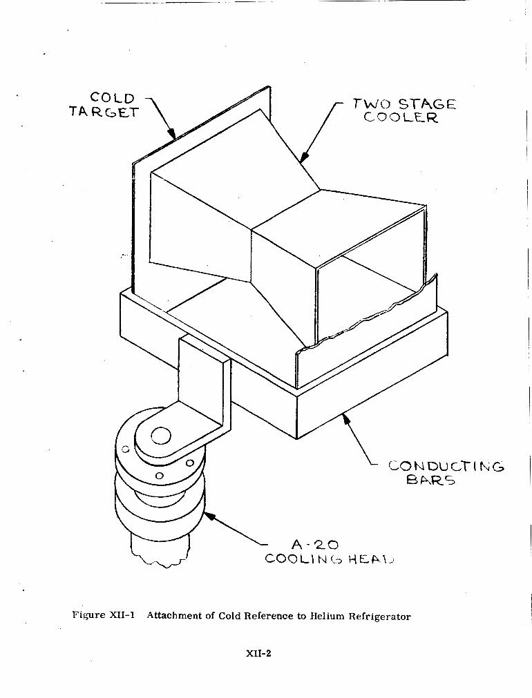
I The following calculations cover the application of a Norelco A-20 helium refrigerator to the cooler test program (Section 5.1). The calculations show that’ it is feasible to use the A-20 with a solid copper shield (Figure XII-1) attached to its cold head within the space chamber to conduct the heat away from the surface viewed by the radiant cooler.
I - The total delta T across the copper sideplates is approximately 2 degrees K, based on a copper sheet 1/2 cm thick. If we can increase this .thickness to 1 cm, we can effectively halve the delta T. W e have also calculated the temperature drop across the conducting bars to the A-20 head assuming the copper bars are 2 . 5 cm thick and 10 cm wide. This temperature difference is approximately 10 degrees K. Again we can help ourselves by increasing the conductive cross- sectional area. However, the weight of the set-up is already about 120 pounds, which will require some internal support of the copper shield.
It is interesting to note that, based on available data, there are several coppers which have a higher thermal conductivity than OFHC copper. The high purity annealed copper has a conductivity five times higher and would reduce the total weight by 75 to 80 percent. To date we have had very little success in determining the availability of this high purity copper.
The 77 degrees K shroud around the outside of the copper shield can be cooled by attachment to the first stage of the A-20 refrigerator.
A somewhat simplified calculation of the temperature distribution in the shield can be made following some reasonable assumptions:
1. The temperature of the A-2 0 refrigerator lead is - 25 degrees K;
2. The heat flux on the side plates is uniform;
XII-1
TA
Figure XII-1 Attachment of Cold Reference to Helium Refrigerator
XII-2
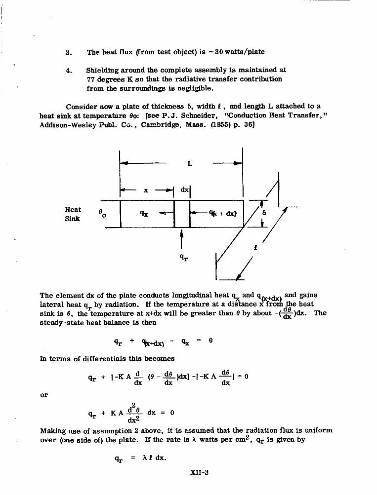
3. The heat flux (from test object) is -30 watts/plate
4. Shielding around the complete assembly is maintained at 77 degrees K so that the radiative transfer contribution from the surroundings is negligible.
Consider nuw a plate of thickness 6, width I , and length L attached to a heat sink at temperature 80: [see P. J. Schneider, "Conduction Heat Transfer, Addison-Wesiey PuH. Co., Czdxidge; Mass. (1955) p. 361
Heat Sink
The element dx of the plate conducts longitudinal heat 4~ and q x+dx and gains
sink is 8, the temperature at x+dx will be greater than 8 by about - \dx)dx. The steady-state heat balance is then
de lateral heat qr by radiation. If the temperature at a distance d A fro the heat
qr + %+dx\ - q x = o
In terms of differentials this becomes
or
+ K A - d2 0 dx = 0
dx2 qr
Making use of assumption 2 above, it is assumed that the radiation flux is uniform over (one side of) the plate. If the rate is A watts per cm2, qr is given by
XII-3
The differential equation becomes
d2 8 A 1 + K A - = O dx2
or - = - A i d2 8 - = * dx2 KA
where c = - ‘1 is a positive constant. K A
This equation is satisfied by a sdi i t im r?f the form
ex = CY2 + p x + y
where CY, 8, y are constants to be evaluated by applying the appropriate boundary conditions.
Taking the derivatives we find
next we apply the condition
- - de - o a t x = ~ dx
This implies that there is no flow of heat past the outer edge of the plate, i.e.
de = -KA (-) = 0
qL d x L
x)L = 2 a L + /I = 0 de
;, /I = CL
The remaining boundary condition is
The temperature distribution is given by
-C ex = - x2 + C L X + eo 2
The temperature difference is thus
e X - e = -C xr! + C L X . 0 2
XII-4
At x=L 2 - -c 2 = CL - - L2 + C L
eL -eo 2 2
The constant c can be evaluated from the condition that the total radiation Q on the plate is given by
so A t = % . The following numerical values apply:
1 = 50cm L = 40cm 6 = 0.5cm Q = 30watta K = 12 watts/cm% for OFHC Copper
14 watts/cmOK for Electrolytic Tough Pitch Copper 23 watts/cm% for Coalesced Copper 60 watts/cm% for Hi-Purity Annealed
A = t 6
Using the value for OFHC copper
c = - hP = 30/40 - - - 1 - - .0025 deg K/cm2 K A 1 2 x 5 0 ~ 0.5 400
The temperature drop across the plate is then
A similar calculation assuming all the heat into the top end of the plate (at x=L) gives a temperature difference of 4.0 degrees K which is still within limit&.
Considering the bottom crossbar which supports the end plates under the assumption of uniform loading along the length of the bar as in the above calcula- tion, the temperature difference amounts to 2.5 degrees K. (In this case the cross sectional area is 1 0 cm x 2.5 cm and the length is 50 cm).
The crossbar supporting the end plates is considered as if all the heat flux from the end bars is conducted through the cross sectional area of the bar. The defining equation for heat conduction can be applied, viz.
QL KA A 0 = -
XII-5
where symmetry conditions apply
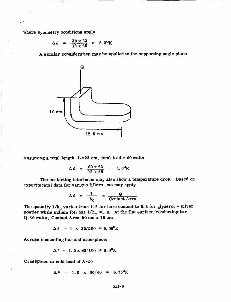
A similar consideration may be applied to the supporting angle piece
10
h 12.5 cm
Assuming a total length L =23 cm, total load = 60 watts
The contacting interfaces may also show a temperature drop. Based on experimental data for various fillers, we may apply
hC Contact Area A 8 = - X B
The quantity l/hc varies from 1.5 for bare contact to 0.3 for glycerol + silver powder while indium foil has l/hc m l . 0. At the flat surface/conducting bar Q=30 watts, Contact Area=5O cm x 10 cm
Across conducting bar and crosspiece:
Croespiece to cold lead of A-20
MI-6
I ,
The tdtal At9 from plates to A-20 lead is then 2.5 + 2.3 = 4.8% at conducting bar 4. 6OK at crosspiece
.6 + .75 + .06 = 1.4OK at interfaces total 10.8%
The A-20 lead will operate at approximately 17 degrees K so the temper- ature in the warmest part of the end plates is -29 to 30 degrees K.
Doubling the thicirneee of c~:;wr =add reduce the At9's by - 1/2, and further improvement could be expected if the high purity copper can be employed.
The total amount of copper is:
Plates Bars
2 x 0.5 x 40 x 50 = 2000 cm3 (50 + 50 + 55) x 25 x 10 = 3900 cm3 (23) x2.5 x 10 = 600cm3
6500 cm3 Weight 9 gr x 6500 = 58,500 grams
-120 lbs.
XII-7


![The Advanced Microwave Radiometer – Climate Quality (AMR-C) … · 2018-03-08 · Microwave Radiometer (HRMR) [6] and a Supplemental Calibration System (SCS). The radiometer channels](https://img.pdfslide.us/doc/110x75/5f35db4eb6ba30245530385e/the-advanced-microwave-radiometer-a-climate-quality-amr-c-2018-03-08-microwave.jpg)