Embed Size (px)
Citation preview

IPHA Technical Seminar 2015 October 21-22, Malmö - Sweden
Shear resistance of hollowcore slabs
Ronald Klein-Holte
VBI Ontwikkeling bv
1
Technical Seminar 2015, October 21-22, Malmö - Sweden
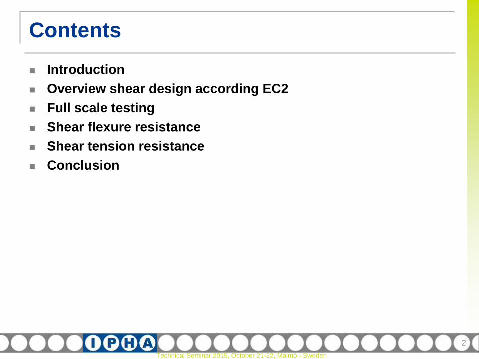
Contents
Introduction
Overview shear design according EC2
Full scale testing
Shear flexure resistance
Shear tension resistance
Conclusion
2

Technical Seminar 2015, October 21-22, Malmö - Sweden
Introduction
As long as pre-stressed hollow core slabs exists as long as
there are questions about their shear resistance
The shear tension capacity of a slab element is well known now.
But what about…
Shear flexure capacity?
Influence of structural topping?
Influence of filled cores?
Interaction shear and bending?
3

Technical Seminar 2015, October 21-22, Malmö - Sweden
Introduction
Shear failure modes in cracked and uncracked regions
4
anchorage
Technical Seminar 2015, October 21-22, Malmö - Sweden
EC2 Design
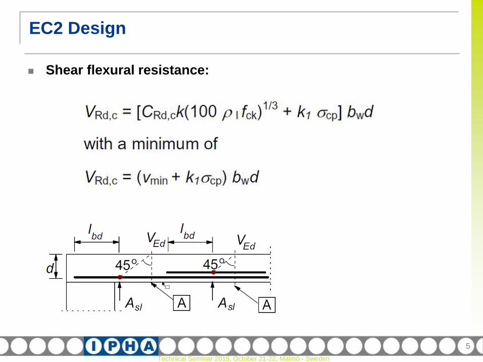
Shear flexural resistance:
5
Technical Seminar 2015, October 21-22, Malmö - Sweden
EC2 Design
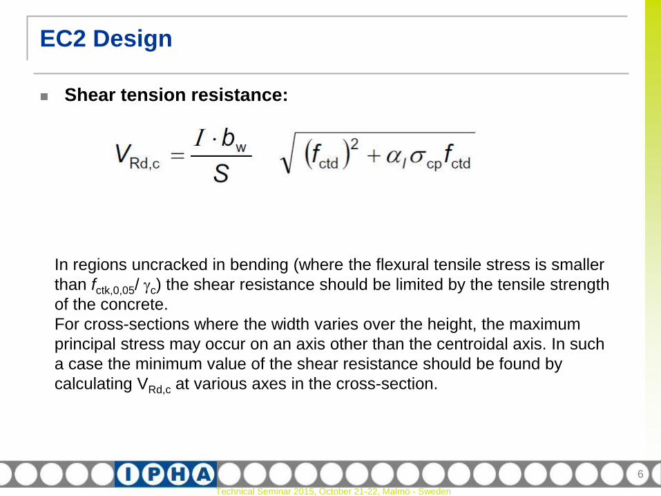
Shear tension resistance:
6
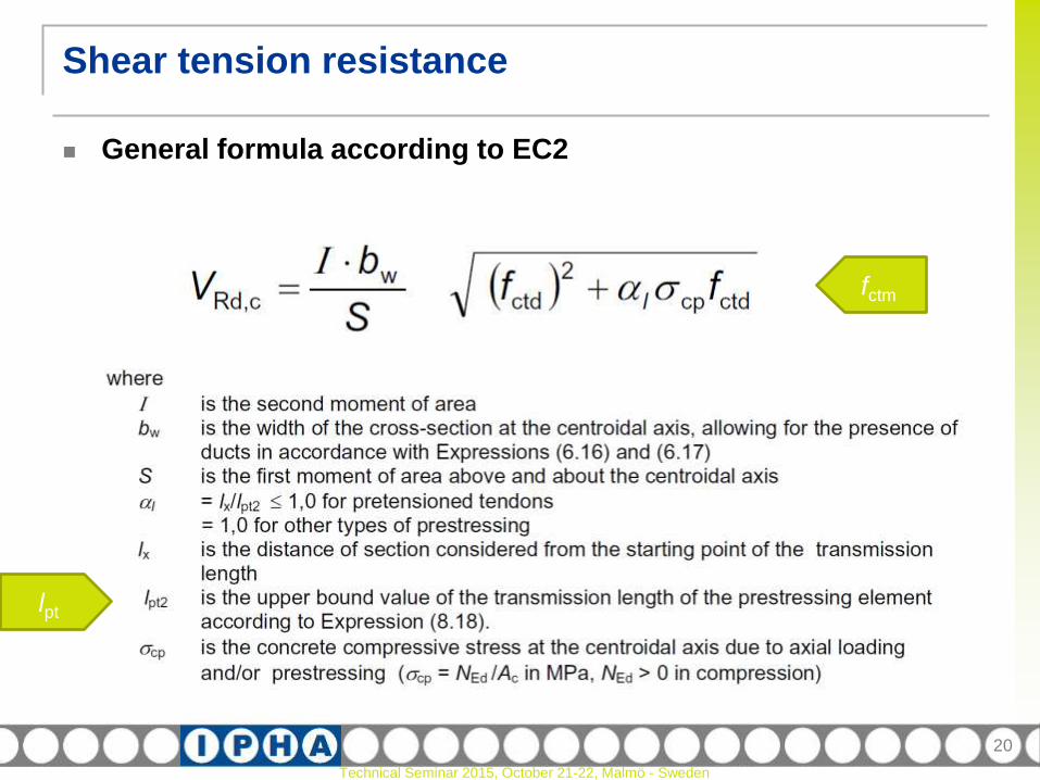
In regions uncracked in bending (where the flexural tensile stress is smaller
than fctk,0,05/ c) the shear resistance should be limited by the tensile strength
of the concrete.
For cross-sections where the width varies over the height, the maximum
principal stress may occur on an axis other than the centroidal axis. In such
a case the minimum value of the shear resistance should be found by
calculating VRd,c at various axes in the cross-section.

Technical Seminar 2015, October 21-22, Malmö - Sweden
EC2 Design
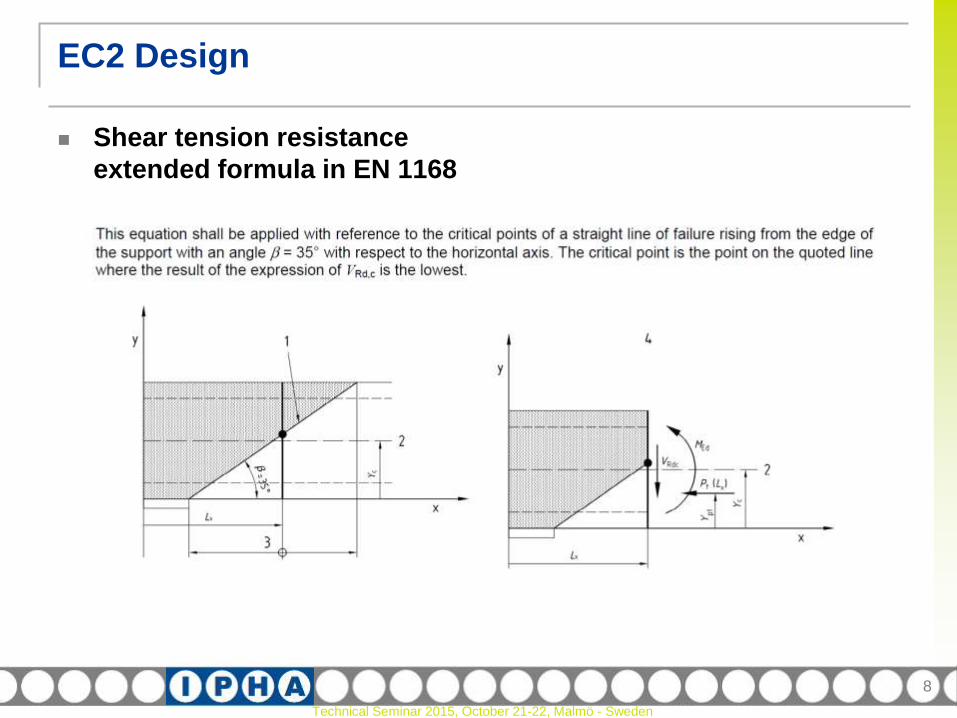
Shear tension resistance
extended formula in EN 1168
7
Technical Seminar 2015, October 21-22, Malmö - Sweden
Shear tension resistance
extended formula in EN 1168
EC2 Design
8

Technical Seminar 2015, October 21-22, Malmö - Sweden
EC2 Design
Anchorage
9
For members with shear reinforcement the additional tensile force, Ftd,
should be calculated according to 6.2.3 (7). For members without shear
reinforcement Ftd may be estimated by shifting the moment curve a
distance al = d according to 6.2.2 (5). This "shift rule“ may also be used as
an alternative for members with shear reinforcement.
Technical Seminar 2015, October 21-22, Malmö - Sweden
EC2 Design
Anchorage
10
Anchorage of tensile force for the ultimate limit state
The anchorage of tendons should be checked in sections where the
concrete tensile stress exceeds fctk,0,05. The tendon force should be
calculated for a cracked section, including the effect of shear according to
6.2.3 (6); see also 9.2.1.3.
Where the concrete tensile stress is less than fctk,0,05, no anchorage check
is necessary.
Technical Seminar 2015, October 21-22, Malmö - Sweden
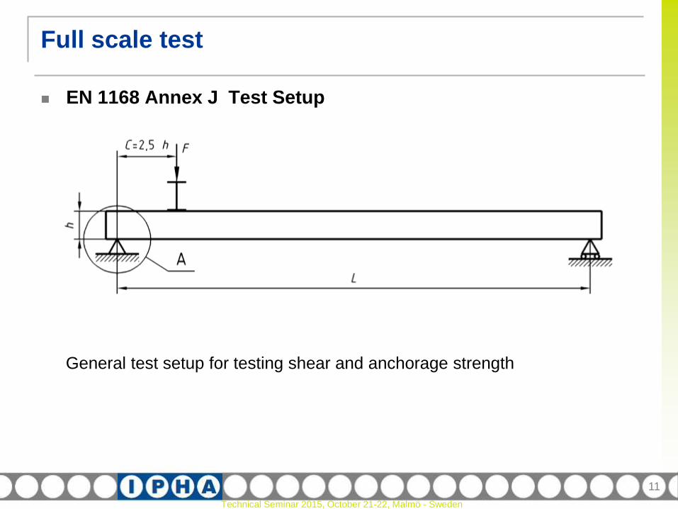
Full scale test
EN 1168 Annex J Test Setup
11
General test setup for testing shear and anchorage strength
Technical Seminar 2015, October 21-22, Malmö - Sweden
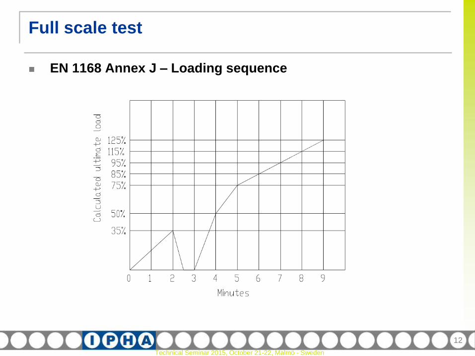
Full scale test
EN 1168 Annex J – Loading sequence
12

Technical Seminar 2015, October 21-22, Malmö - Sweden
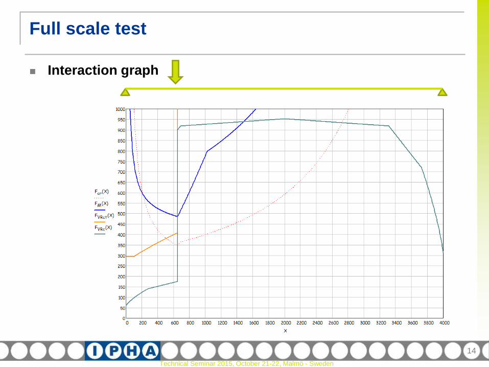
Full scale test
Calculating the expected failure load
Mean material strength
Design principles based on this mean material strength
e.g.:
The bond strength based on mean tensile strength (anchorage)
Transfer of pre-stress based on mean transmission length
13
Technical Seminar 2015, October 21-22, Malmö - Sweden
Full scale test
Interaction graph
14
Technical Seminar 2015, October 21-22, Malmö - Sweden
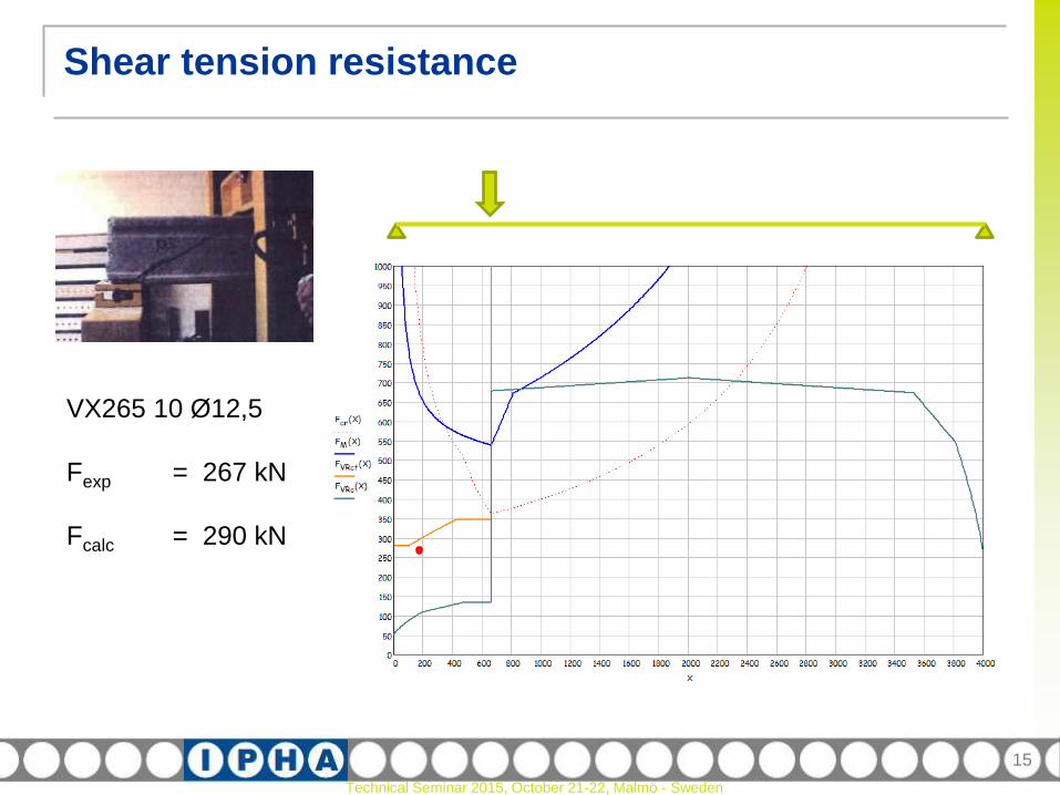
Shear tension resistance
15
VX265 10 Ø12,5
Fexp = 267 kN
Fcalc = 290 kN

Technical Seminar 2015, October 21-22, Malmö - Sweden
Shear flexure resistance
16
CRd,c = 0,18
no material factor
Equivalent tensile reinforcement:
Asl x( )Fanchorage x( )
500
Reinforcement ratio:
1 x( ) minAsl x( )
bw x( ) d0.020
fck = fcm
Effective depth of total
cross section
(structural topping included)

Technical Seminar 2015, October 21-22, Malmö - Sweden
Shear flexure resistance
17
A260 12 Ø12,5
no topping
Fexp = 284 kN
Fcalc = 300 kN

Technical Seminar 2015, October 21-22, Malmö - Sweden
Shear flexure resistance
18
A260 12 Ø12,5
50 mm topping
Fexp = 353 kN
Fcalc = 351 kN

Technical Seminar 2015, October 21-22, Malmö - Sweden
Shear flexure resistance
19
A260 12 Ø12,5
100 mm topping
Fexp = 430 kN
Fcalc = 411 kN
Technical Seminar 2015, October 21-22, Malmö - Sweden
Shear tension resistance
General formula according to EC2
20
lpt
fctm
Technical Seminar 2015, October 21-22, Malmö - Sweden
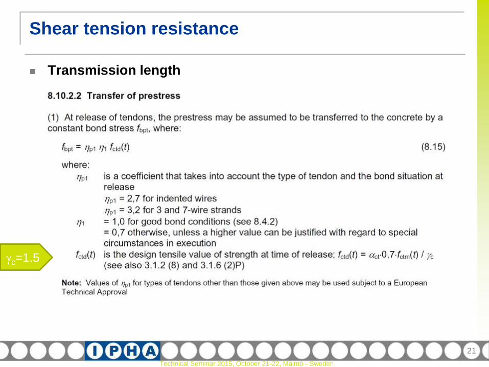
Shear tension resistance
Transmission length
21
c=1.5

Technical Seminar 2015, October 21-22, Malmö - Sweden
Transmission length
Shear tension resistance
22
Technical Seminar 2015, October 21-22, Malmö - Sweden
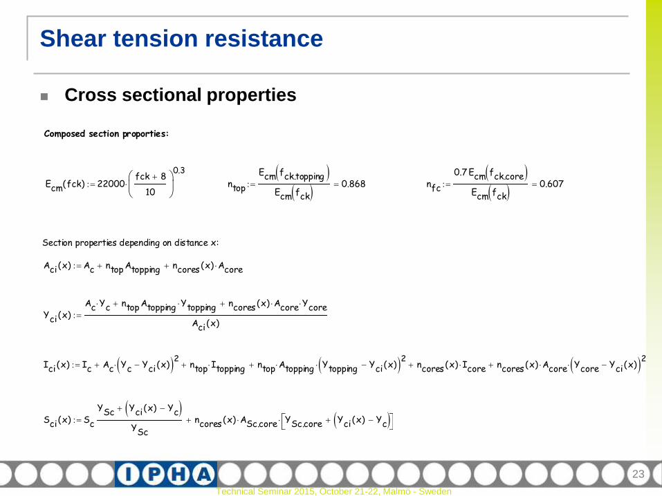
Cross sectional properties
Shear tension resistance
23
Composed section proporties:
Ecm fck( ) 22000fck 8
10
0.3
ntop
Ecm fck.topping Ecm fck
0.868 nfc
0.7 Ecm fck.core Ecm fck
0.607
Section properties depending on distance x:
Aci x( ) Ac ntop Atopping ncores x( ) Acore
Yci x( )Ac Yc ntop Atopping Ytopping ncores x( ) Acore Ycore
Aci x( )
Ici x( ) Ic Ac Yc Yci x( ) 2 ntop Itopping ntop Atopping Ytopping Yci x( ) 2 ncores x( ) Icore ncores x( ) Acore Ycore Yci x( ) 2
Sci x( ) Sc
YSc Yci x( ) Yc
YSc
ncores x( ) ASc.core YSc.core Yci x( ) Yc
Technical Seminar 2015, October 21-22, Malmö - Sweden
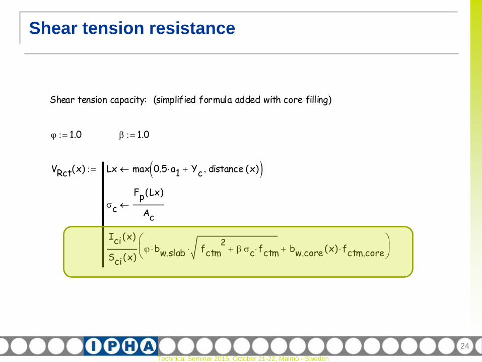
Shear tension resistance
24
Shear tension capacity: (simplified formula added with core filling)
1.0 1.0
VRct x( ) Lx max 0.5 a1 Yc distance x( )
c
Fp Lx( )
Ac
Ici x( )
Sci x( ) bw.slab fctm
2 c fctm bw.core x( ) fctm.core
Technical Seminar 2015, October 21-22, Malmö - Sweden
Shear tension resistance
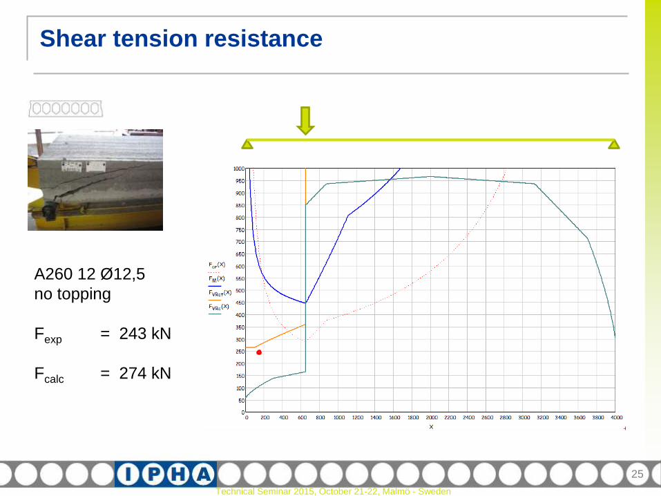
25
A260 12 Ø12,5
no topping
Fexp = 243 kN
Fcalc = 274 kN

Technical Seminar 2015, October 21-22, Malmö - Sweden
Shear tension resistance
26
A260 12 Ø12,5
50 mm topping
Fexp = 299 kN
Fcalc = 336 kN
Technical Seminar 2015, October 21-22, Malmö - Sweden
Shear tension resistance
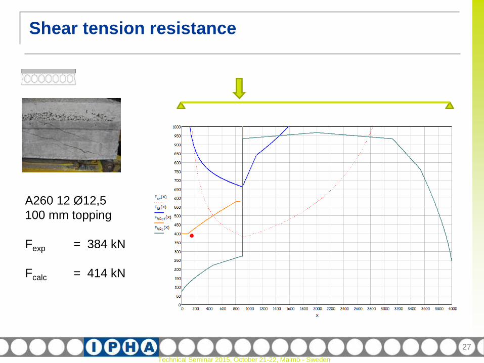
27
A260 12 Ø12,5
100 mm topping
Fexp = 384 kN
Fcalc = 414 kN
Technical Seminar 2015, October 21-22, Malmö - Sweden
Filled cores
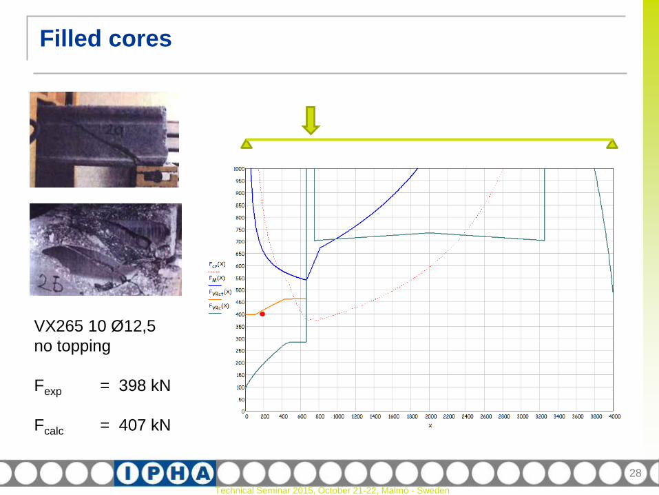
28
VX265 10 Ø12,5
no topping
Fexp = 398 kN
Fcalc = 407 kN
Technical Seminar 2015, October 21-22, Malmö - Sweden
Filled cores
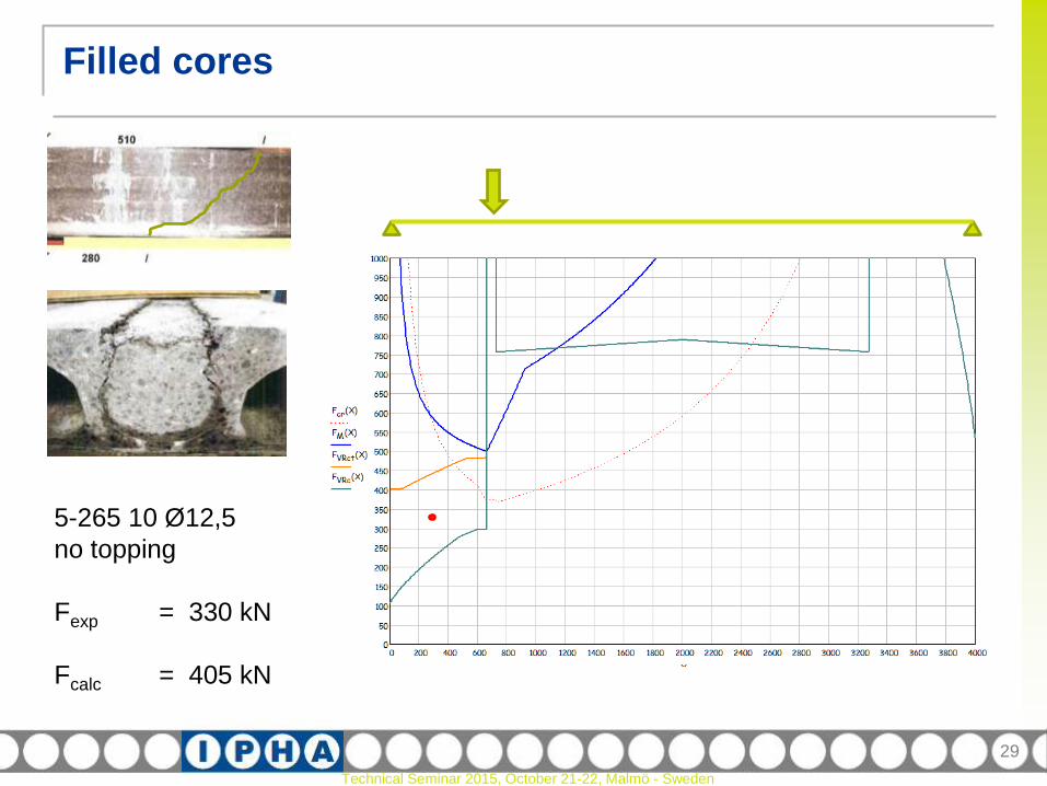
29
5-265 10 Ø12,5
no topping
Fexp = 330 kN
Fcalc = 405 kN

Technical Seminar 2015, October 21-22, Malmö - Sweden
Filled cores
30
260 5 Ø12,5
no topping
Fexp = 340 kN
Fcalc = 350 kN
Technical Seminar 2015, October 21-22, Malmö - Sweden
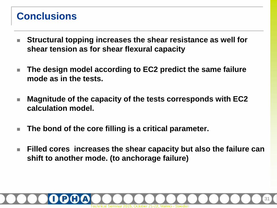
Conclusions
Structural topping increases the shear resistance as well for
shear tension as for shear flexural capacity
The design model according to EC2 predict the same failure
mode as in the tests.
Magnitude of the capacity of the tests corresponds with EC2
calculation model.
The bond of the core filling is a critical parameter.
Filled cores increases the shear capacity but also the failure can
shift to another mode. (to anchorage failure)
31


![DESIGNING COMPOSITE BEAMS WITH PRECAST HOLLOWCORE SLABS …ascjournal.com/down/vol3no2/vol3no2_6.pdf · DESIGNING COMPOSITE BEAMS WITH PRECAST HOLLOWCORE SLABS ... 2 [5] for concrete](https://img.pdfslide.us/doc/110x75/5a71d9b57f8b9ab6538d11c2/designing-composite-beams-with-precast-hollowcore-slabs-ascjournalcomdownvol3no2vol3no26pdfpdf.jpg)