Embed Size (px)
Citation preview

Autumn 2003 CSE370 - VII - Finite State Machines 1
Finite State Machines
Sequential circuitsprimitive sequential elementscombinational logic
Models for representing sequential circuitsfinite-state machines (Moore and Mealy)
Basic sequential circuits revisitedshift registerscounters
Design procedurestate diagramsstate transition tablenext state functions
Hardware description languages
Autumn 2003 CSE370 - VII - Finite State Machines 2
Abstraction of state elements
Divide circuit into combinational logic and stateLocalize the feedback loops and make it easy to break cyclesImplementation of storage elements leads to various forms of sequential logic
CombinationalLogic
Storage Elements
Outputs
State OutputsState Inputs
Inputs
Autumn 2003 CSE370 - VII - Finite State Machines 3
Forms of sequential logic
Asynchronous sequential logic – state changes occur whenever state inputs change (elements may be simple wires or delay elements)Synchronous sequential logic – state changes occur in lock step across all storage elements (using a periodic waveform - the clock)
Clock
Autumn 2003 CSE370 - VII - Finite State Machines 4
In = 0
In = 1
In = 0In = 1
100
010
110
111001
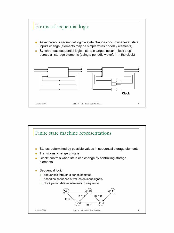
Finite state machine representations
States: determined by possible values in sequential storage elementsTransitions: change of stateClock: controls when state can change by controlling storage elements
Sequential logicsequences through a series of statesbased on sequence of values on input signalsclock period defines elements of sequence

Autumn 2003 CSE370 - VII - Finite State Machines 5
Example finite state machine diagram
Combination lock from introduction to course5 states5 self-transitions6 other transitions between states1 reset transition (from all states) to state S1
resetS3
closed
closedmux=C1 equal
& new
not equal& new
not equal& new
not equal& new
not newnot newnot new
S1 S2 OPEN
ERR
closedmux=C2 equal
& new
closedmux=C3 equal
& new
open
Autumn 2003 CSE370 - VII - Finite State Machines 6
Can any sequential system be represented with a state diagram?
Shift registerinput value shownon transition arcsoutput values shownwithin state node
100 110
111
011
101010000
001
1
1
1
1
0
0
00
1
1
1
0
0
1
00
D Q D Q D QIN
OUT1 OUT2 OUT3
CLK

Autumn 2003 CSE370 - VII - Finite State Machines 7
010
100
110
011001
000
101111
3-bit up-counter
Counters are simple finite state machines
Countersproceed through well-defined sequence of states in response to enable
Many types of counters: binary, BCD, Gray-code3-bit up-counter: 000, 001, 010, 011, 100, 101, 110, 111, 000, ...3-bit down-counter: 111, 110, 101, 100, 011, 010, 001, 000, 111, ...
Autumn 2003 CSE370 - VII - Finite State Machines 8
How do we turn a state diagram into logic?
Counter3 flip-flops to hold statelogic to compute next stateclock signal controls when flip-flop memory can change
wait long enough for combinational logic to compute new valuedon't wait too long as that is low performance
D Q D Q D Q
OUT1 OUT2 OUT3
CLK
"1"

Autumn 2003 CSE370 - VII - Finite State Machines 9
FSM design procedure
Start with counterssimple because output is just statesimple because no choice of next state based on input
State diagram to state transition tabletabular form of state diagramlike a truth-table
State encodingdecide on representation of statesfor counters it is simple: just its value
Implementationflip-flop for each state bitcombinational logic based on encoding
Autumn 2003 CSE370 - VII - Finite State Machines 10
010
100
110
011001
000
101111
3-bit up-counter
current state next state0 000 001 11 001 010 22 010 011 33 011 100 44 100 101 55 101 110 66 110 111 77 111 000 0
FSM design procedure: state diagram to encoded state transition table
Tabular form of state diagramLike a truth-table (specify output for all input combinations)Encoding of states: easy for counters – just use value

Autumn 2003 CSE370 - VII - Finite State Machines 11
C3 C2 C1 N3 N2 N10 0 0 0 0 10 0 1 0 1 00 1 0 0 1 10 1 1 1 0 01 0 0 1 0 11 0 1 1 1 01 1 0 1 1 11 1 1 0 0 0
N1 <= C1’N2 <= C1C2’ + C1’C2
<= C1 xor C2N3 <= C1C2C3’ + C1’C3 + C2’C3
<= (C1C2)C3’ + (C1’ + C2’)C3<= (C1C2)C3’ + (C1C2)’C3<= (C1C2) xor C3
Verilog notation to showfunction represents an input to D-FF
Implementation
D flip-flop for each state bitCombinational logic based on encoding
0 0
0 1
1 1
0 1C1
C2
C3N3
0 1
1 0
1 0
0 1C1
C2
C3N2
1 1
0 0
1 1
0 0C1
C2
C3N1
Autumn 2003 CSE370 - VII - Finite State Machines 12
In C1 C2 C3 N1 N2 N30 0 0 0 0 0 00 0 0 1 0 0 00 0 1 0 0 0 10 0 1 1 0 0 10 1 0 0 0 1 00 1 0 1 0 1 00 1 1 0 0 1 10 1 1 1 0 1 11 0 0 0 1 0 01 0 0 1 1 0 01 0 1 0 1 0 11 0 1 1 1 0 11 1 0 0 1 1 01 1 0 1 1 1 01 1 1 0 1 1 11 1 1 1 1 1 1
N1 <= InN2 <= C1N3 <= C2
Back to the shift register
Input determines next state
100 110
111
011
101010000
001
0
1
1 1
11
1
1
0
0
0
0 0
1
00
D Q D Q D QIN
OUT1 OUT2 OUT3
CLK

Autumn 2003 CSE370 - VII - Finite State Machines 13
More complex counter example
Complex counterrepeats 5 states in sequencenot a binary number representation
Step 1: derive the state transition diagramcount sequence: 000, 010, 011, 101, 110
Step 2: derive the state transition table from the state transition diagram
Present State Next StateC B A C+ B+ A+0 0 0 0 1 00 0 1 – – –0 1 0 0 1 10 1 1 1 0 11 0 0 – – –1 0 1 1 1 01 1 0 0 0 01 1 1 – – –
note the don't care conditions that arise from the unused state codes
010
000 110
101
011
Autumn 2003 CSE370 - VII - Finite State Machines 14
C+ <= A
B+ <= B’ + A’C’
A+ <= BC’
More complex counter example (cont’d)
Step 3: K-maps for next state functions
0 0
X 1
0 X
X 1A
B
CC+
1 1
X 0
0 X
X 1A
B
CB+
0 1
X 1
0 X
X 0A
B
CA+

Autumn 2003 CSE370 - VII - Finite State Machines 15
Self-starting counters (cont’d)
Re-deriving state transition table from don't care assignment
0 0
1 1
0 0
1 1A
B
CC+
1 1
1 0
0 1
0 1A
B
CB+
0 1
0 1
0 0
0 0A
B
CA+
Present State Next StateC B A C+ B+ A+0 0 0 0 1 00 0 1 1 1 00 1 0 0 1 10 1 1 1 0 11 0 0 0 1 01 0 1 1 1 01 1 0 0 0 01 1 1 1 0 0
010
000 110
101
011
001111
100
Autumn 2003 CSE370 - VII - Finite State Machines 16
Self-starting counters
Start-up statesat power-up, counter may be in an unused or invalid statedesigner must guarantee that it (eventually) enters a valid state
Self-starting solutiondesign counter so that invalid states eventually transition to a valid statemay limit exploitation of don't cares
implementationon previous slide
010
000 110
101
011
001111
100
010
000 110
101
011
001 111
100

Autumn 2003 CSE370 - VII - Finite State Machines 17
Activity
2-bit up-down counter (2 inputs)direction: D = 0 for up, D = 1 for downcount: C = 0 for hold, C = 1 for count
01
00 11
10
C=0D=X
C=0D=X
C=0D=X
C=0D=X
C=1D=0
C=1D=0
C=1D=0
C=1D=0
C=1D=1
S1 S0 C D N1 N00 0 0 0 0 00 0 0 1 0 00 0 1 0 0 10 0 1 1 1 10 1 0 0 0 10 1 0 1 0 10 1 1 0 1 00 1 1 1 0 01 0 0 0 1 01 0 0 1 1 01 0 1 0 1 11 0 1 1 0 11 1 0 0 1 11 1 0 1 1 11 1 1 0 0 01 1 1 1 1 0
Autumn 2003 CSE370 - VII - Finite State Machines 18
Activity (cont’d)
S1 S0 C D N1 N00 0 0 0 0 00 0 0 1 0 00 0 1 0 0 10 0 1 1 1 10 1 0 0 0 10 1 0 1 0 10 1 1 0 1 00 1 1 1 0 01 0 0 0 1 01 0 0 1 1 01 0 1 0 1 11 0 1 1 0 11 1 0 0 1 11 1 0 1 1 11 1 1 0 0 01 1 1 1 1 0
N1 = C’S1+ CDS0’S1’ + CDS0S1+ CD’S0S1’ + CD’S0’S1
= C’S1+ C(D’(S1 ⊕ S0) + D(S1 ≡ S0))
N0 = CS0’ + C’S00 1 1 0
0 1 1 0
1 0 0 1
1 0 0 1
D
S1
S0
C
0 0 1 1
0 0 1 1
1 0 1 0
0 1 0 1
D
S1
S0
C

Autumn 2003 CSE370 - VII - Finite State Machines 19
Counter/shift-register model
Values stored in registers represent the state of the circuitCombinational logic computes:
next statefunction of current state and inputs
outputsvalues of flip-flops
Inputs
Outputs
Next State
Current State
next statelogic
Autumn 2003 CSE370 - VII - Finite State Machines 20
General state machine model
Values stored in registers represent the state of the circuitCombinational logic computes:
next statefunction of current state and inputs
outputsfunction of current state and inputs (Mealy machine)function of current state only (Moore machine)
InputsOutputs
Next State
Current State
outputlogic
next statelogic
Autumn 2003 CSE370 - VII - Finite State Machines 21
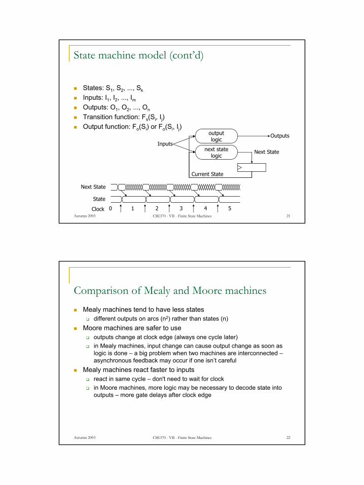
State machine model (cont’d)
States: S1, S2, ..., Sk
Inputs: I1, I2, ..., ImOutputs: O1, O2, ..., On
Transition function: Fs(Si, Ij)Output function: Fo(Si) or Fo(Si, Ij)
InputsOutputs
Next State
Current State
outputlogic
next statelogic
Clock
Next State
State
0 1 2 3 4 5
Autumn 2003 CSE370 - VII - Finite State Machines 22
Comparison of Mealy and Moore machinesMealy machines tend to have less states
different outputs on arcs (n2) rather than states (n)Moore machines are safer to use
outputs change at clock edge (always one cycle later)in Mealy machines, input change can cause output change as soon as logic is done – a big problem when two machines are interconnected –asynchronous feedback may occur if one isn’t careful
Mealy machines react faster to inputsreact in same cycle – don't need to wait for clockin Moore machines, more logic may be necessary to decode state into outputs – more gate delays after clock edge

Autumn 2003 CSE370 - VII - Finite State Machines 23
Comparison of Mealy and Moore machines (cont’d)
Moore
Mealy
Synchronous Mealy
state feedback
inputs
outputsreg
combinational logic for next state logic for
outputs
inputs outputs
state feedback
regcombinational
logic fornext state
logic foroutputs
inputs outputs
state feedback
regcombinational
logic fornext state
logic foroutputs
Autumn 2003 CSE370 - VII - Finite State Machines 24
D/1
E/1
B/0
A/0
C/0
1
0
0
00
1
1
1
1
0
reset
current nextreset input state state output1 – – A0 0 A B 00 1 A C 00 0 B B 00 1 B D 00 0 C E 00 1 C C 00 0 D E 10 1 D C 10 0 E B 10 1 E D 1
Specifying outputs for a Moore machine
Output is only function of statespecify in state bubble in state diagramexample: sequence detector for 01 or 10

Autumn 2003 CSE370 - VII - Finite State Machines 25
current nextreset input state state output1 – – A 00 0 A B 00 1 A C 00 0 B B 00 1 B C 10 0 C B 10 1 C C 0
B
A
C
0/1
0/0
0/0
1/1
1/0
1/0
reset/0
Specifying outputs for a Mealy machine
Output is function of state and inputsspecify output on transition arc between statesexample: sequence detector for 01 or 10
Autumn 2003 CSE370 - VII - Finite State Machines 26
Registered Mealy machine (really Moore)
Synchronous (or registered) Mealy machineregistered state AND outputsavoids ‘glitchy’ outputseasy to implement in PLDs
Moore machine with no output decodingoutputs computed on transition to next state rather than after enteringview outputs as expanded state vector
InputsOutputs
Current State
outputlogic
next statelogic

Autumn 2003 CSE370 - VII - Finite State Machines 27
VendingMachine
FSM
N
D
Reset
Clock
OpenCoinSensor
ReleaseMechanism
Example: vending machine
Release item after 15 cents are depositedSingle coin slot for dimes, nickelsNo change
Autumn 2003 CSE370 - VII - Finite State Machines 28
Example: vending machine (cont’d)
Suitable abstract representationtabulate typical input sequences:
3 nickelsnickel, dimedime, nickeltwo dimes
draw state diagram:inputs: N, D, resetoutput: open chute
assumptions:assume N and D assertedfor one cycleeach state has a self loopfor N = D = 0 (no coin)
S0
Reset
S2
D
S6[open]
D
S4[open]
D
S1
N
S3
N
S5[open]
N
S8[open]
D
S7[open]
N

Autumn 2003 CSE370 - VII - Finite State Machines 29
Example: vending machine (cont’d)
Minimize number of states - reuse states whenever possible
symbolic state table
present inputs next outputstate D N state open
0¢ 0 0 0¢ 00 1 5¢ 01 0 10¢ 01 1 – –
5¢ 0 0 5¢ 00 1 10¢ 01 0 15¢ 01 1 – –
10¢ 0 0 10¢ 00 1 15¢ 01 0 15¢ 01 1 – –
15¢ – – 15¢ 1
0¢
Reset
5¢
N
N
N + D
10¢
D
15¢[open]
D
Autumn 2003 CSE370 - VII - Finite State Machines 30
present state inputs next state outputQ1 Q0 D N D1 D0 open0 0 0 0 0 0 0
0 1 0 1 01 0 1 0 01 1 – – –
0 1 0 0 0 1 00 1 1 0 01 0 1 1 01 1 – – –
1 0 0 0 1 0 00 1 1 1 01 0 1 1 01 1 – – –
1 1 – – 1 1 1
Example: vending machine (cont’d)
Uniquely encode states

Autumn 2003 CSE370 - VII - Finite State Machines 31
D1 = Q1 + D + Q0 N
D0 = Q0’ N + Q0 N’ + Q1 N + Q1 D
OPEN = Q1 Q0
Example: Moore implementation
Mapping to logic0 0 1 1
0 1 1 1
X X 1 X
1 1 1 1
Q1D1
Q0
ND
0 1 1 0
1 0 1 1
X X 1 X
0 1 1 1
Q1D0
Q0
ND
0 0 1 0
0 0 1 0
X X 1 X
0 0 1 0
Q1Open
Q0
ND
Autumn 2003 CSE370 - VII - Finite State Machines 32
present state inputs next state outputQ3 Q2 Q1 Q0 D N D3 D2 D1 D0 open0 0 0 1 0 0 0 0 0 1 0
0 1 0 0 1 0 01 0 0 1 0 0 01 1 - - - - -
0 0 1 0 0 0 0 0 1 0 00 1 0 1 0 0 01 0 1 0 0 0 01 1 - - - - -
0 1 0 0 0 0 0 1 0 0 00 1 1 0 0 0 01 0 1 0 0 0 01 1 - - - - -
1 0 0 0 - - 1 0 0 0 1
D0 = Q0 D’ N’
D1 = Q0 N + Q1 D’ N’
D2 = Q0 D + Q1 N + Q2 D’ N’
D3 = Q1 D + Q2 D + Q2 N + Q3
OPEN = Q3
Example: vending machine (cont’d)
One-hot encoding

Autumn 2003 CSE370 - VII - Finite State Machines 33
Equivalent Mealy and Moore state diagrams
Moore machineoutputs associated with state
0¢[0]
10¢[0]
5¢[0]
15¢[1]
N’ D’ + Reset
D
D
N
N+D
N
N’ D’
Reset’
N’ D’
N’ D’
Reset
0¢
10¢
5¢
15¢
(N’ D’ + Reset)/0
D/0
D/1
N/0
N+D/1
N/0
N’ D’/0
Reset’/1
N’ D’/0
N’ D’/0
Reset/0
Mealy machineoutputs associated with transitions
Autumn 2003 CSE370 - VII - Finite State Machines 34
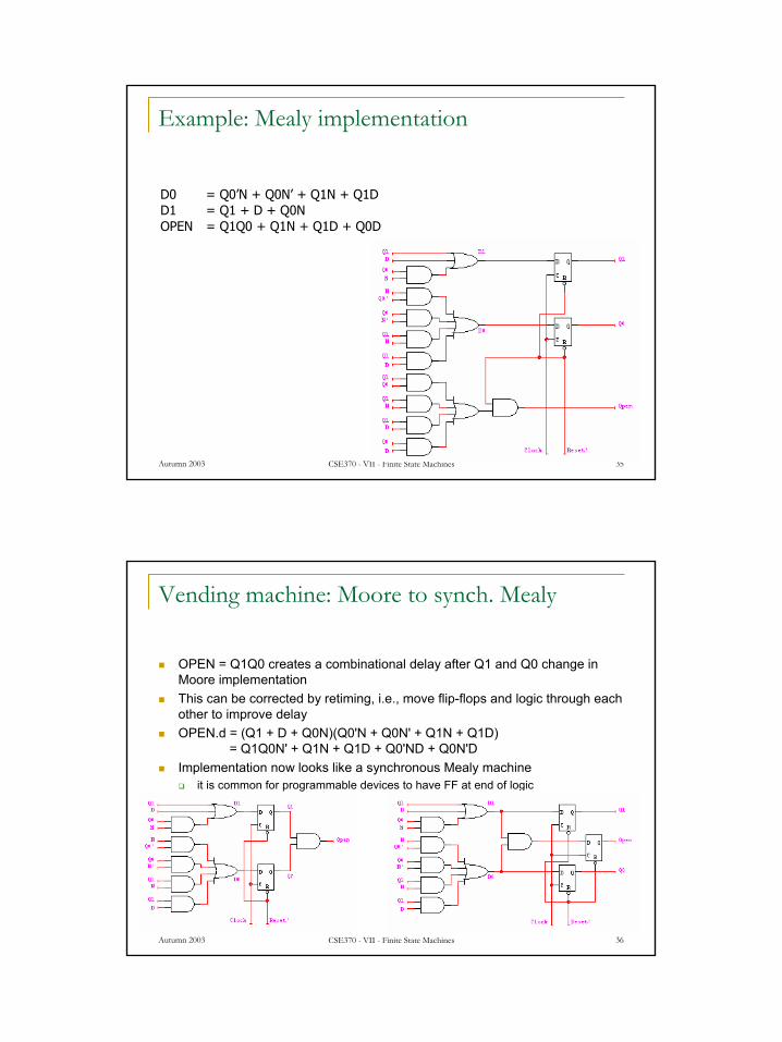
Example: Mealy implementation
0¢
10¢
5¢
15¢
(N’ D’ + Reset)/0
D/0
D/1
N/0
N+D/1
N/0
N’ D’/0
Reset’/1
N’ D’/0
N’ D’/0
Reset/0present state inputs next state output
Q1 Q0 D N D1 D0 open0 0 0 0 0 0 0
0 1 0 1 01 0 1 0 01 1 – – –
0 1 0 0 0 1 00 1 1 0 01 0 1 1 11 1 – – –
1 0 0 0 1 0 00 1 1 1 11 0 1 1 11 1 – – –
1 1 – – 1 1 1
D0 = Q0’N + Q0N’ + Q1N + Q1DD1 = Q1 + D + Q0NOPEN = Q1Q0 + Q1N + Q1D + Q0D
0 0 1 0
0 0 1 1
X X 1 X
0 1 1 1
Q1Open
Q0
ND
Autumn 2003 CSE370 - VII - Finite State Machines 35
Example: Mealy implementation
D0 = Q0’N + Q0N’ + Q1N + Q1DD1 = Q1 + D + Q0NOPEN = Q1Q0 + Q1N + Q1D + Q0D
Autumn 2003 CSE370 - VII - Finite State Machines 36
Vending machine: Moore to synch. Mealy
OPEN = Q1Q0 creates a combinational delay after Q1 and Q0 change in Moore implementationThis can be corrected by retiming, i.e., move flip-flops and logic through each other to improve delayOPEN.d = (Q1 + D + Q0N)(Q0'N + Q0N' + Q1N + Q1D)
= Q1Q0N' + Q1N + Q1D + Q0'ND + Q0N'DImplementation now looks like a synchronous Mealy machine
it is common for programmable devices to have FF at end of logic

Autumn 2003 CSE370 - VII - Finite State Machines 37
Vending machine: Mealy to synch. Mealy
OPEN.d = Q1Q0 + Q1N + Q1D + Q0DOPEN.d = (Q1 + D + Q0N)(Q0'N + Q0N' + Q1N + Q1D)
= Q1Q0N' + Q1N + Q1D + Q0'ND + Q0N'D
0 0 1 0
0 0 1 1
1 0 1 1
0 1 1 1
Q1Open.d
Q0
ND
0 0 1 0
0 0 1 1
X X 1 X
0 1 1 1
Q1Open.d
Q0
ND
Autumn 2003 CSE370 - VII - Finite State Machines 38
D Q
QB
A
clock
out
D Q
Q
D Q
Qclock
outA
B
Mealy and Moore examples
Recognize A,B = 0,1Mealy or Moore?
B
A out

Autumn 2003 CSE370 - VII - Finite State Machines 39
D Q
Q
D Q
Q
D Q
Q
D Q
Q
A
B
clock
out
D Q
Q
D Q
Q
A
B
clock
out
Mealy and Moore examples (cont’d)
Recognize A,B = 1,0 then 0,1Mealy or Moore?
Autumn 2003 CSE370 - VII - Finite State Machines 40
Hardware Description Languages and Sequential Logic
Flip-flopsrepresentation of clocks - timing of state changesasynchronous vs. synchronous
FSMsstructural view (FFs separate from combinational logic)behavioral view (synthesis of sequencers – not in this course)
Data-paths = data computation (e.g., ALUs, comparators) + registers
use of arithmetic/logical operatorscontrol of storage elements

Autumn 2003 CSE370 - VII - Finite State Machines 41
Example: reduce-1-string-by-1
Remove one 1 from every string of 1s on the input
1
0
0
0
11
zero[0]
one1[0]
two1s[1]
1/00/0
0/0
1/1
zero[0]
one1[0]
Moore Mealy
Autumn 2003 CSE370 - VII - Finite State Machines 42
parameter zero = 2’b00;parameter one1 = 2’b01;parameter two1s = 2’b10;
module reduce (clk, reset, in, out);input clk, reset, in;output out;reg out;reg [2:1] state; // state variablesreg [2:1] next_state;
always @(posedge clk)if (reset) state = zero;else state = next_state;
state assignment (easy to change, if in one place)
Verilog FSM - Reduce 1s example
Moore machine
1
0
0
0
11
zero[0]
one1[0]
two1s[1]

Autumn 2003 CSE370 - VII - Finite State Machines 43
always @(in or state)
case (state)zero:
// last input was a zerobeginif (in) next_state = one1;else next_state = zero;
endone1:
// we've seen one 1beginif (in) next_state = two1s;else next_state = zero;
endtwo1s:
// we've seen at least 2 onesbeginif (in) next_state = two1s;else next_state = zero;
endendcase
crucial to include all signals that are input to state determination
Moore Verilog FSM (cont’d)
note that output depends only on state
always @(state)case (state)zero: out = 0;one1: out = 0;two1s: out = 1;
endcase
endmodule
Autumn 2003 CSE370 - VII - Finite State Machines 44
module reduce (clk, reset, in, out);input clk, reset, in;output out;reg out;reg state; // state variablesreg next_state;
always @(posedge clk)if (reset) state = zero;else state = next_state;
always @(in or state)case (state)zero: // last input was a zerobeginout = 0;if (in) next_state = one;else next_state = zero;
endone: // we've seen one 1if (in) begin
next_state = one; out = 1;end else begin
next_state = zero; out = 0;end
endcaseendmodule
Mealy Verilog FSM
1/00/0
0/0
1/1
zero[0]
one1[0]

Autumn 2003 CSE370 - VII - Finite State Machines 45
module reduce (clk, reset, in, out);input clk, reset, in;output out;reg out;reg state; // state variables
always @(posedge clk)if (reset) state = zero;else case (state)zero: // last input was a zerobeginout = 0;if (in) state = one;else state = zero;
endone: // we've seen one 1if (in) begin
state = one; out = 1;end else begin
state = zero; out = 0;end
endcaseendmodule
Synchronous Mealy Machine
Autumn 2003 CSE370 - VII - Finite State Machines 46
Finite state machines summary
Models for representing sequential circuitsabstraction of sequential elementsfinite state machines and their state diagramsinputs/outputsMealy, Moore, and synchronous Mealy machines
Finite state machine design procedurederiving state diagramderiving state transition tabledetermining next state and output functionsimplementing combinational logic
Hardware description languages