Embed Size (px)
Citation preview

ECE 322
Digital Design with VHDL
Lecture 18
Finite State Machine

California State University
Textbook References
Finite state machine Stephen Brown and Zvonko Vranesic, Fundamentals of Digital Logic with VHDL Design, 2nd or 3rd Edition Chapter 8, Synchronous Sequential Circuits
In this lecture, we introduce the general structure of a
digital system and state the role of finite state machine
(FSM) in its operation.

California State University
There are many ways to design finite state
machines as a synchronous sequential circuit
Each results in a different cost and timing
Mealy machines offer another set of possibilities
Output generated based on both the state of the
circuit and the present values of its inputs
Mealy Finite State Machine

California State University
Circuits that detect the occurrence of a particular
pattern on its input(s) are referred to as
sequence detectors.
Design a sequence detector circuit that detects if
two or more consecutive 1s occur on its input w.
Clock cycle: t 0 t 1 t 2 t 3 t 4 t 5 t 6 t 7 t 8 t 9 t 10
w : 0 1 0 1 1 0 1 1 1 0 1
z : 0 0 0 0 1 0 0 1 1 0 0
First Example on Mealy-type FSM: Sequence Detector

California State University
Slightly different specifications
Difference:
Original: z = 1 in the clock cycle that follows the
second occurrence of w = 1
New: z = 1 in the same clock cycle when the
second occurrence of w = 1 is detected
Clock cycle: t 0 t 1 t 2 t 3 t 4 t 5 t 6 t 7 t 8 t 9 t 10
w : 0 1 0 1 1 0 1 1 1 0 1
z : 0 0 0 0 1 0 0 1 1 0 0
Step 1. Specification

California State University
State diagram of an FSM that realizes the task
A
w 0 = z 0 =
w 1 = z 1 = B w 0 = z 0 =
Reset
w 1 = z 0 =
Step 2. State Diagram

California State University
State table for Mealy FSM
Present Next state Output z
state w = 0 w = 1 w = 0 w = 1
A A B 0 0
B A B 0 1
Step 3. State Table

California State University
State-assigned table for the FSM
Present Next state Output
state w = 0 w = 1 w = 0 w = 1
y Y Y z z
A 0 0 1 0 0
B 1 0 1 0 1
Step 4. State Assignment
California State University
Step 5. Next-State and Output Logic Expressions
Y = D = w
z = wy
Assuming that y is realized as a D-type flip-flop, the required
next-state and output expressions are

California State University
Clock
Resetn
D Q
Q
w
z
y
Step 6. Implementation
Implementation of Mealy FSM
California State University
t 0 t 1 t 2 t 3 t 4 t 5 t 6 t 7 t 8 t 9 t 10
1
0
1
0
1
0
1
0
Clock
y
w
z
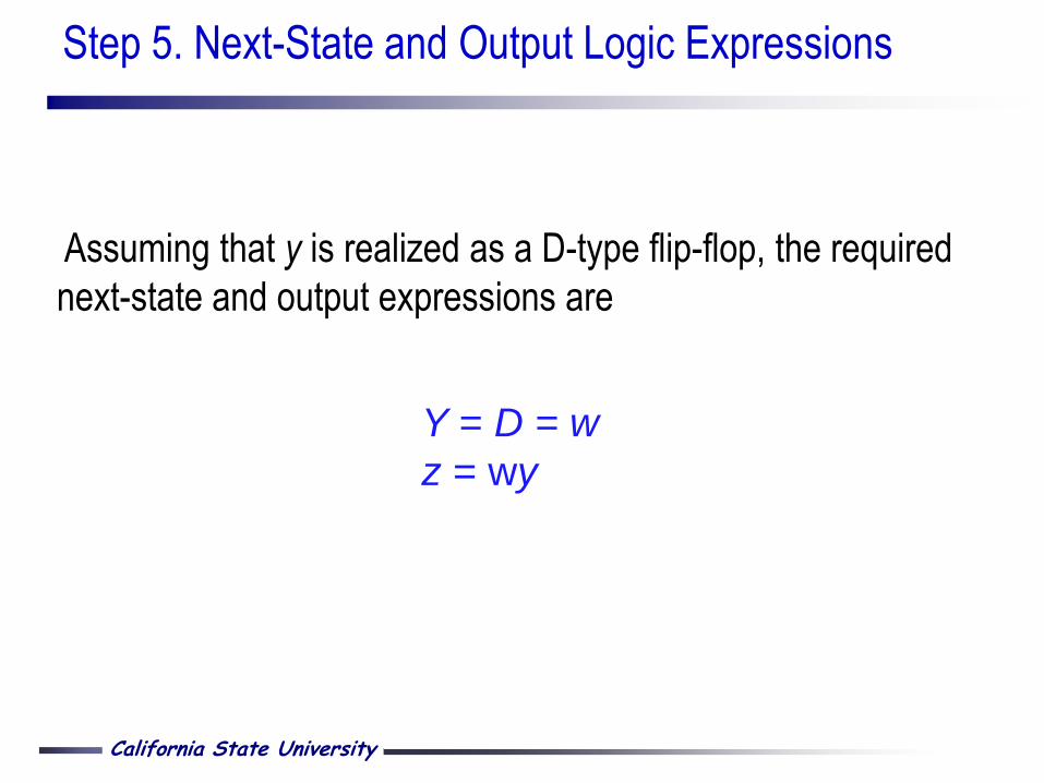
Timing diagram
Timing Diagram for Mealy-type FSM
California State University
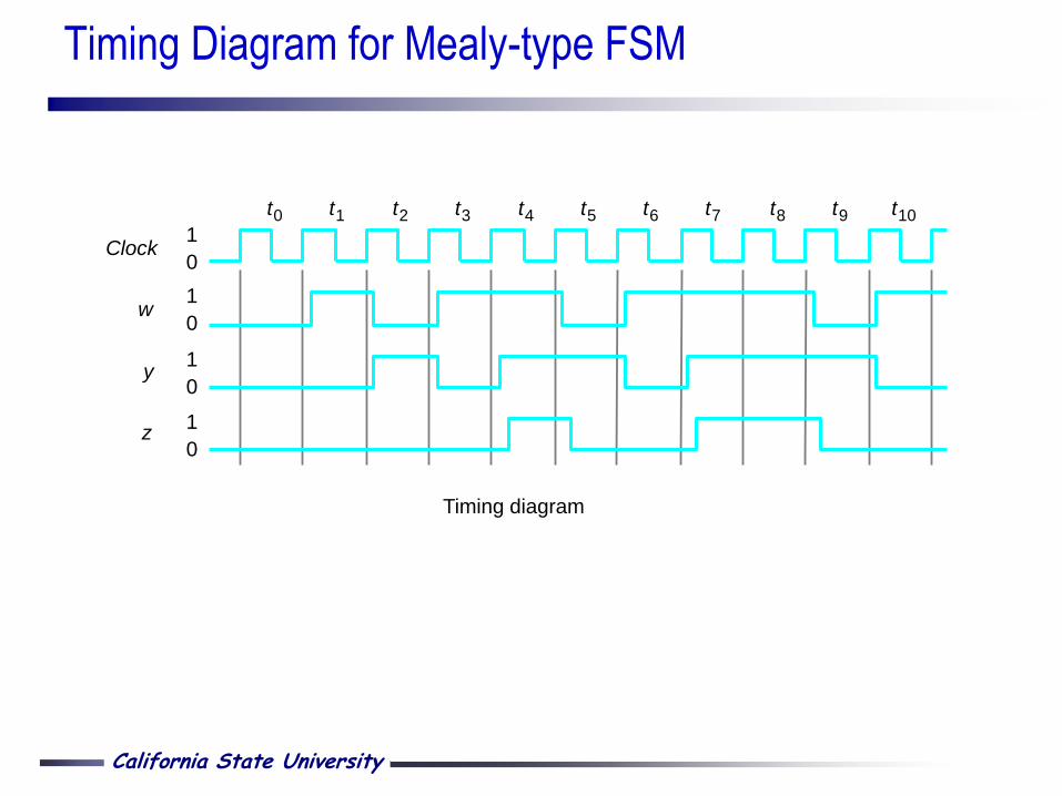
Circuit that implements the Moore-type machine specification
Circuit and Timing Diagram for Moore-type FSM
Clock
Resetn
D Q
Q
w
z
(a) Circuit
t 0 t 1 t 2 t 3 t 4 t 5 t 6 t 7 t 8 t 9 t 10
1
0
1
0
1
0
1
0
Clock
y
w
z
y
(b) Timing diagram
D Q
Q
Z
1
0 Z

California State University
R 3 out 1 = R 1 in 1 = Done 1 = , , w 0 = w 1 =
R 1 out 1 = R 2 in 1 = ,
w 1 = R 2 out 1 = R 3 in 1 = ,
A
w 0 = w 1 =
Reset
w 0 =
B
C
• Requires 3 instead of 4 states
• Still requires 2 flip-flops
• Timing is different: Generates
output control signals one
clock cycle sooner
• Entire process takes 3
instead of 4 cycles for the
Moore machine
Second Example on Mealy-type FSM: Bus Control Circuit

California State University
Rudimentary method:
•Use the design technique previously described to
design the next state logic, output logic and flip- flop
circuits
•Use schematic diagrams or structural VHDL to
describe these circuits. E.g. use components for the
flip flops, etc…
•Use CAD tools to simulate the behavior
•Use CAD tools to automatically implement the circuit
in a chip, such as a PLD
Design of FSM Using VHDL

California State University
• Design the state diagram and let the CAD tools
synthesize a FSM from it.
• CAD tools take care of synthesis and optimizations
(state assignment, logic/state minimization).
• Enter the state diagram into CAD tools
• Draw using a graphical editor
• Use behavioral VHDL (more common) behavioral
VHDL (more common)
Behavioral Description

California State University
Remarks:
The process block is required to synthesize a
behavioral VHDL description of a synchronous
sequential circuit
You can alternatively use structural VHDL (FF
components) and purely concurrent statements
Sequential Circuits for FSM Implementation

California State University
LIBRARY ieee ;
USE ieee.std_logic_1164.all ;
ENTITY flipflop IS
PORT ( D, Clock : IN STD_LOGIC ;
Q : OUT STD_LOGIC) ;
END flipflop ;
ARCHITECTURE behavioral OF flipflop IS
BEGIN
PROCESS ( Clock )
BEGIN
IF Clock'EVENT AND Clock = '1' THEN
Q <= D ;
END IF ;
END PROCESS ;
END behavioral ;
Recall: VHDL Code for a D-type Flip-Flop
California State University
There are many ways to describe a FSM in VHDL
We will describe 2 ways
Example: Moore-type sequence detector
First Possible VHDL Code
California State University
First Possible VHDL Code for Moore-type Sequence Detector(1)
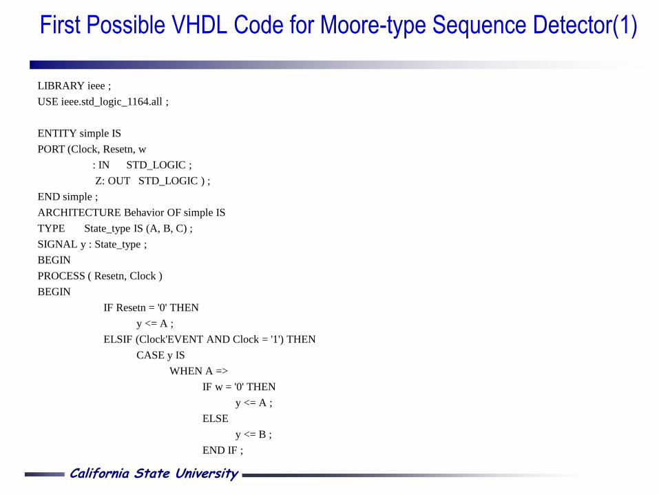
LIBRARY ieee ;
USE ieee.std_logic_1164.all ;
ENTITY simple IS
PORT (Clock, Resetn, w
: IN STD_LOGIC ;
Z: OUT STD_LOGIC ) ;
END simple ;
ARCHITECTURE Behavior OF simple IS
TYPE State_type IS (A, B, C) ;
SIGNAL y : State_type ;
BEGIN
PROCESS ( Resetn, Clock )
BEGIN
IF Resetn = '0' THEN
y <= A ;
ELSIF (Clock'EVENT AND Clock = '1') THEN
CASE y IS
WHEN A =>
IF w = '0' THEN
y <= A ;
ELSE
y <= B ;
END IF ;
California State University
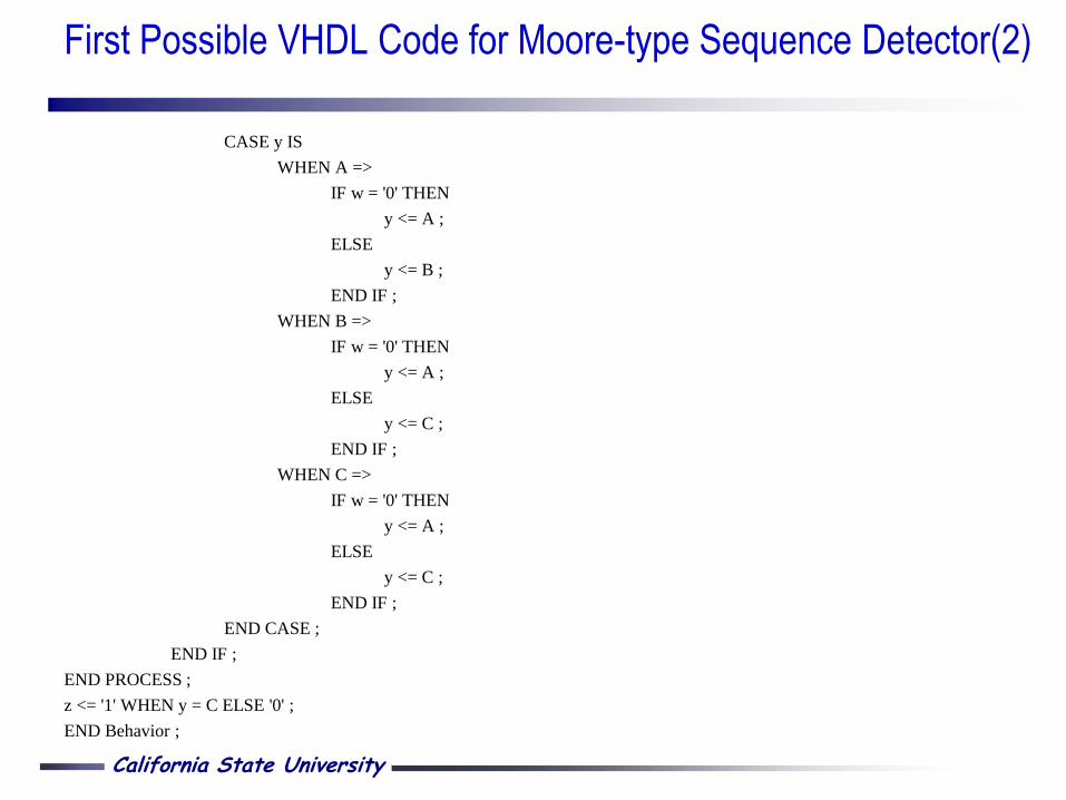
CASE y IS
WHEN A =>
IF w = '0' THEN
y <= A ;
ELSE
y <= B ;
END IF ;
WHEN B =>
IF w = '0' THEN
y <= A ;
ELSE
y <= C ;
END IF ;
WHEN C =>
IF w = '0' THEN
y <= A ;
ELSE
y <= C ;
END IF ;
END CASE ;
END IF ;
END PROCESS ;
z <= '1' WHEN y = C ELSE '0' ;
END Behavior ;
First Possible VHDL Code for Moore-type Sequence Detector(2)

California State University
Remarks on first possible VHDL code for Moore-type sequence
detector:
The VHDL synthesizer will automatically creates the states
i.e. it chooses the number of flip-flops to use and the
assignment of state variable values to the state symbolic
labels A, B, and C.
CAD assumes the first state listed is the reset state and
assigns it so that all FF outputs are equal to 0
First Possible VHDL Code for Moore-type Sequence Detector
California State University
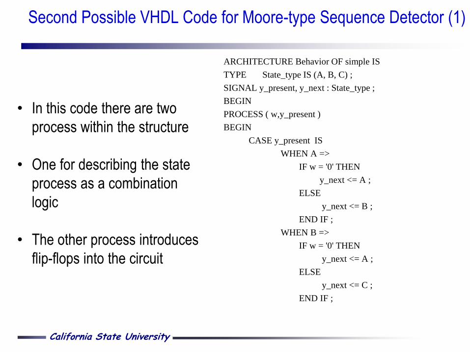
ARCHITECTURE Behavior OF simple IS
TYPE State_type IS (A, B, C) ;
SIGNAL y_present, y_next : State_type ;
BEGIN
PROCESS ( w,y_present )
BEGIN
CASE y_present IS
WHEN A =>
IF w = '0' THEN
y_next <= A ;
ELSE
y_next <= B ;
END IF ;
WHEN B =>
IF w = '0' THEN
y_next <= A ;
ELSE
y_next <= C ;
END IF ;
• In this code there are two
process within the structure
• One for describing the state
process as a combination
logic
• The other process introduces
flip-flops into the circuit
Second Possible VHDL Code for Moore-type Sequence Detector (1)

California State University
WHEN C =>
IF w = '0' THEN
y_next <= A ;
ELSE
y_next <= C ;
END IF ;
END CASE ;
END PROCESS ;
PROCESS ( Resetn, Clock )
BEGIN
IF Resetn = '0' THEN
y_present <= A ;
ELSIF (Clock'EVENT AND Clock =
'1') THEN
y_present <= y_next ;
END IF ;
END PROCESS ;
z <= '1' WHEN y = C ELSE '0' ;
END Behavoir;
Second Possible VHDL Code for Moore-type Sequence Detector (2)
California State University
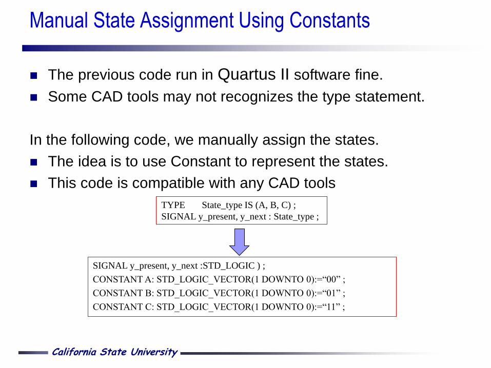
The previous code run in Quartus II software fine.
Some CAD tools may not recognizes the type statement.
In the following code, we manually assign the states.
The idea is to use Constant to represent the states.
This code is compatible with any CAD tools
SIGNAL y_present, y_next :STD_LOGIC ) ;
CONSTANT A: STD_LOGIC_VECTOR(1 DOWNTO 0):=“00” ;
CONSTANT B: STD_LOGIC_VECTOR(1 DOWNTO 0):=“01” ;
CONSTANT C: STD_LOGIC_VECTOR(1 DOWNTO 0):=“11” ;
Manual State Assignment Using Constants
TYPE State_type IS (A, B, C) ;
SIGNAL y_present, y_next : State_type ;

California State University
ARCHITECTURE Behavior OF mealy IS
TYPE State_type IS (A, B) ;
SIGNAL y : State_type ;
BEGIN
PROCESS ( Resetn, Clock )
BEGIN
IF Resetn = '0' THEN
y <= A ;
ELSIF (Clock'EVENT AND Clock = '1') THEN
CASE y IS
WHEN A =>
IF w = '0' THEN y <= A ;
ELSE y <= B ;
END IF ;
WHEN B =>
IF w = '0' THEN y <= A ;
ELSE y <= B ;
END IF ;
END CASE ;
END IF ;
END PROCESS ;
A
w 0 = z 0 =
w 1 = z 1 = B w 0 = z 0 =
Reset
w 1 = z 0 =
VHDL Code for Mealy-type Sequence Detector
California State University
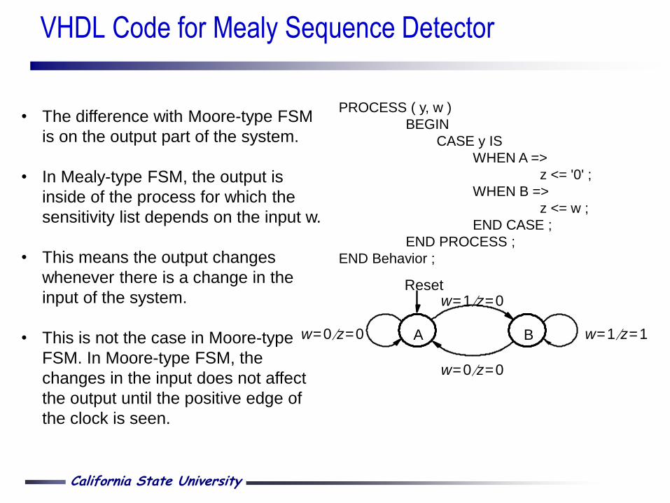
PROCESS ( y, w )
BEGIN
CASE y IS
WHEN A =>
z <= '0' ;
WHEN B =>
z <= w ;
END CASE ;
END PROCESS ;
END Behavior ;
A
w 0 = z 0 =
w 1 = z 1 = B w 0 = z 0 =
Reset w 1 = z 0 =
• The difference with Moore-type FSM
is on the output part of the system.
• In Mealy-type FSM, the output is
inside of the process for which the
sensitivity list depends on the input w.
• This means the output changes
whenever there is a change in the
input of the system.
• This is not the case in Moore-type
FSM. In Moore-type FSM, the
changes in the input does not affect
the output until the positive edge of
the clock is seen.
VHDL Code for Mealy Sequence Detector
California State University
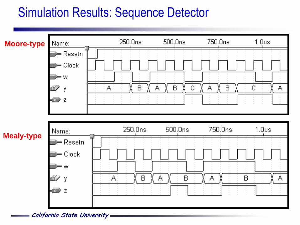
Simulation Results: Sequence Detector
Moore-type
Mealy-type