Embed Size (px)
Citation preview
International Journal of Scientific & Engineering Research, Volume 8, Issue 4, April-2017 ISSN 2229-5518
261
IJSER © 2017
http://www.ijser.org
Finite Element Analysis of Fatigue Crack Growth Rate of Spur Gear Tooth
Swapnil S.Shinde1, Prof. M. A. Mohite
2
1,2 Department of Mechanical Engg, Sinhgad Institute of Technology, Lonavala, India
Abstract—Spur gear is the main source of power transmission in different gearbox system. The bending fatigue is a common
mode of fatigue failure of a spur gear. It means that progressively damage of spur gear tooth and leads to complete failure of a
spur gear. The initial crack is locate at the point where continuously cyclic stress is acting on spur gear tooth. There are two
types of crack first one crack initiation and second crack propagation. If crack created on the gear tooth root then it goes on in-
creasing. i.e. crack growth till complete break of tooth in two parts. The completely bending fatigue of spur gear is mainly di-
vided into two parts crack initiation period and crack propagation period. Under the range of operating conditions, were Ana-
lytical performed by using standard specimens which were made up of structural steel. Mechanical APDL 17.2 is use for simula-
tion. The crack propagation rate is determined by plotting the graph of the crackgrowth (da) versus cycles (dN). The complete
service life of a spur gear can be then determine from no. of stress cycles required for fatigue initiations and no. of stress cycles
for a crack propagate. The functional relationship between the stress intensity factor (ΔK) and crack length(da) which is use for
determination of the required number of loading cycles (N) for a crack propagation from the initial to the critical length. The
service life of spur gear can be found out using Paris Law which isbase on crack propagation rate and difference of Stress Inten-
sity Factor.
Index Terms—FCGR, Service Life,Standard Specimen,Paris Law,SIF,Crack Length
———————————————————
1 INTRODUCTION
Till today the most of the gears are failed because of crack
growth at the root of gear. It is required to know the facts
about gear failures. It is finding that different methods of
Crack propagation analysis of gears are investigated by differ-
ent research. Thus this research can give more information to
industrial professionals and new researchers. Research in this
field is continuously going on, and still some scope is there.
Gear is used to transmit force and motion from one shaft to
another. The design and function of gears are closely asso-
ciated, since gears are design for a specific function. The gen-
eral types of failure modes in gear teeth include fatigue, im-
pact, wear and plastic deformation, of these, the most common
cause of gear failure is tooth bending fatigue.
It is necessary that the gears should function properlywithout
failure for particular applications and stipulated life cycles.
The gear failure will cause partial or complete failure of the
mechanical systems.
The fracture mechanics approach is used for analysis of bend-
ing fatigue failure. It will predict the remaining useful life of
gears due to crack propagation.
2.Literature Review
[1]Carried out the research work on the Bending fatigue and
contact fatigue characteristics of carburized gears. In this dif-
ferent bending and fatigue characteristic are studied in order
to aim to reduce production costs and improve gear quality
and reliability. The results of this concluded that single tooth
bending fatigue, and contact fatigue tests on production gears
manufactured from EN39B steel (steel A), and experimental
steels B, C and D.[2].presented the work on the analytical
model for mesh stiffness calculation of spur gear pair with on
uniformly distributed tooth root crack. In this paper, an ana-
lytical mesh stiffness calculation model for non-uniformly dis-
tributed toothroot crack along tooth width is proposed based
on previous studies. It enables a good prediction on the mesh
stiffness for a spur gear pair with both incipient and larger
tooth cracks. The results of this concluded that indicate that
both the mesh stiffness and the dynamic response results
show that the proposed analytical model is an alternative me-
thod for mesh stiffness calculation of cracked spur gear pairs
with a good accuracy for both small and large cracks.[3] Car-
ried out the research on the finite element analysis of contact
fatigue and bending fatigue ofa theoretical assembling straight
bevel gear pair. In this work propose a 3D FE model of assem-
bling straight bevel gear pair to analyse the contact fatigue on
the tooth surface and the bending fatigue in the tooth root.
Based on the cumulative fatigue criterion and the stress–life
equation, the key meshing states of the gear pair were investi-
gated for the contact fatigue and the bending fatigue. The re-
sults of the study concluded that the fatigue failure of the driv-
IJSER
International Journal of Scientific & Engineering Research, Volume 8, Issue 4, April-2017 ISSN 2229-5518
262
IJSER © 2017
http://www.ijser.org
ing pinion is the main fatigue failure for the straight bevel gear
pair and the bending fatigue failure is the main fatigue failure
for the driving pinion.[4].carried out the research work on the
analysis of bending fatigue in gears. In this research work a
computational model for the determination of service life with
regard to bending fatigue in a gear tooth root is presented. The
results of the concluded that The Paris equation model is used
to determine the service life of a real spur gear made from
through-hardened steel 42CrMo4[5]presented the work on the
numerical modeling of crack growth in a gear tooth root. In
that computational model for determination of crack growth
in a gear tooth root is presented. Twoloading conditions are
taken into account for normal pulsating force acting at the
highest point of thesingle tooth contact and the moving load
along the tooth flank. The results of the study concluded that
numerical analysis show that the prediction of crack propaga-
tion live and crack path in a gear tooth root are significantly
different for both loading conditionsconsidered.[6]Presented
research work on the simulation of crack propagation in spur
gear tooth for different parameter and its influence on mesh
stiffness. In that a cumulative reduction index (CRI) which
uses a variable crack intersection angle to study the effect of
different gear parameters on total time-varying mesh stiffness
is studied. The results of the concluded that the proposed me-
thod is able to reflect the effect of differentgear parameters
with increased deterioration level on total gear mesh stiffness-
values.[7]presented the research work on the effects of spur
gear tooth spatial crack propagation on gear mesh stiffness. In
this research work influence of crack propagation on the time-
varying Gear Mesh Stiffness (GMS) and also the Load Sharing
Ratio (LSR) is presented. In order to quantitatively define the
spatial crack propagation scenario, the involutes spur gear
tooth geometry cut with a typical double rounded rack is first
determined using two parametric equations. The results of the
study conclude that for the dynamic simulation of gear trans-
mission behavior, and consequently helpful for the monitoring
of gearbox working condition and detection of early crack
damage that may exist in gear sets
3 METHODLOGY
The crack growth rate is analysis by Ansys followed by SEN
specimen. Study the failure of gear theoretical and by taking
the SEN specimen in aAnsys 16 as per standard parameter. By
providing the crack thickness of 0.5mm of crack on gear tooth
root and by Appling 10Mpa load then start crack is generated,
Hence by providing proper mesh around crack the result is
generated, Hence the graph of crack growth (da) v/s number
of cycles ΔN is evaluated.
4. FINITE ELEMENT ANALYSIS XFEM USING SOFTWARE
MECHANICAL APDL 17.2
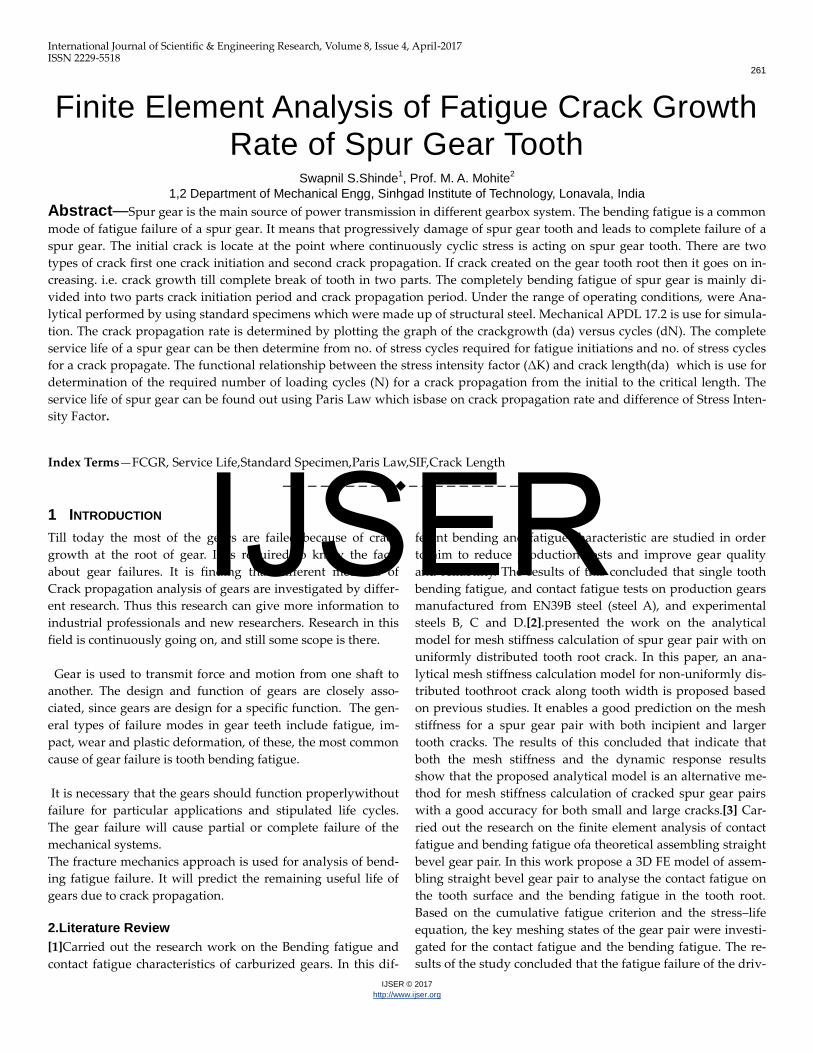
The following Mode I fatigue crack growth simulation using
the XFEM based method. Fatigue crack growth calculations
apply Paris' Law. The analysis uses a SEN specimen with a
crack length (a) to width (W) ratio, a/ W = 0.5
(AllDimensions of SEN Specimen in mm)
Fig.SEN Specimen
The dimension of SEN Specimen:
Width =W=10.0 mm
Height =H=20.0 mm
Initial Crack Length =a=5 mm
Pressure applied on the plate = P=10.0 Mpa.
The material of specimen: Structural steel.
Young’s Modulus, E=2 x10⁵Mpa
Poisson’s Ratio: µ=0.3
Paris Law Constant: 𝐶 = 3x10⁻¹³
𝑚𝑚
𝑐𝑦𝑐𝑙𝑒𝑠
𝑀𝑃𝑎∗ 𝑚𝑚
m=3.0
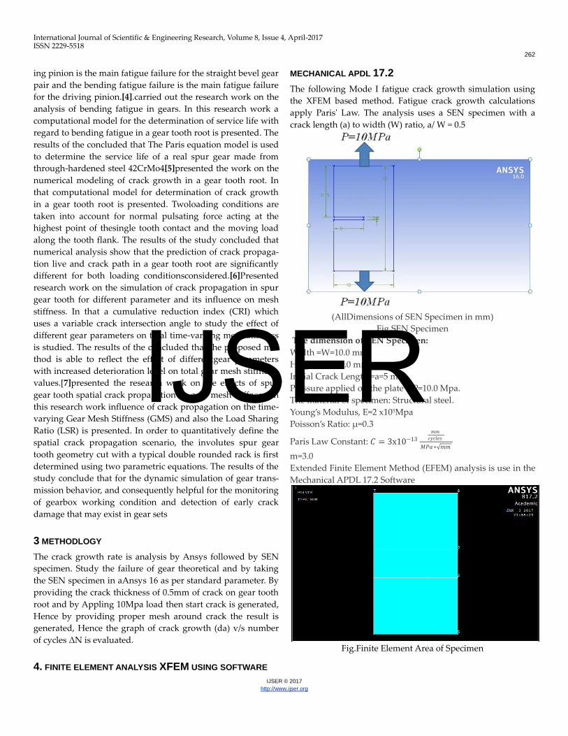
Extended Finite Element Method (EFEM) analysis is use in the
Mechanical APDL 17.2 Software
Fig.Finite Element Area of Specimen
IJSER
International Journal of Scientific & Engineering Research, Volume 8, Issue 4, April-2017 ISSN 2229-5518
263
IJSER © 2017
http://www.ijser.org
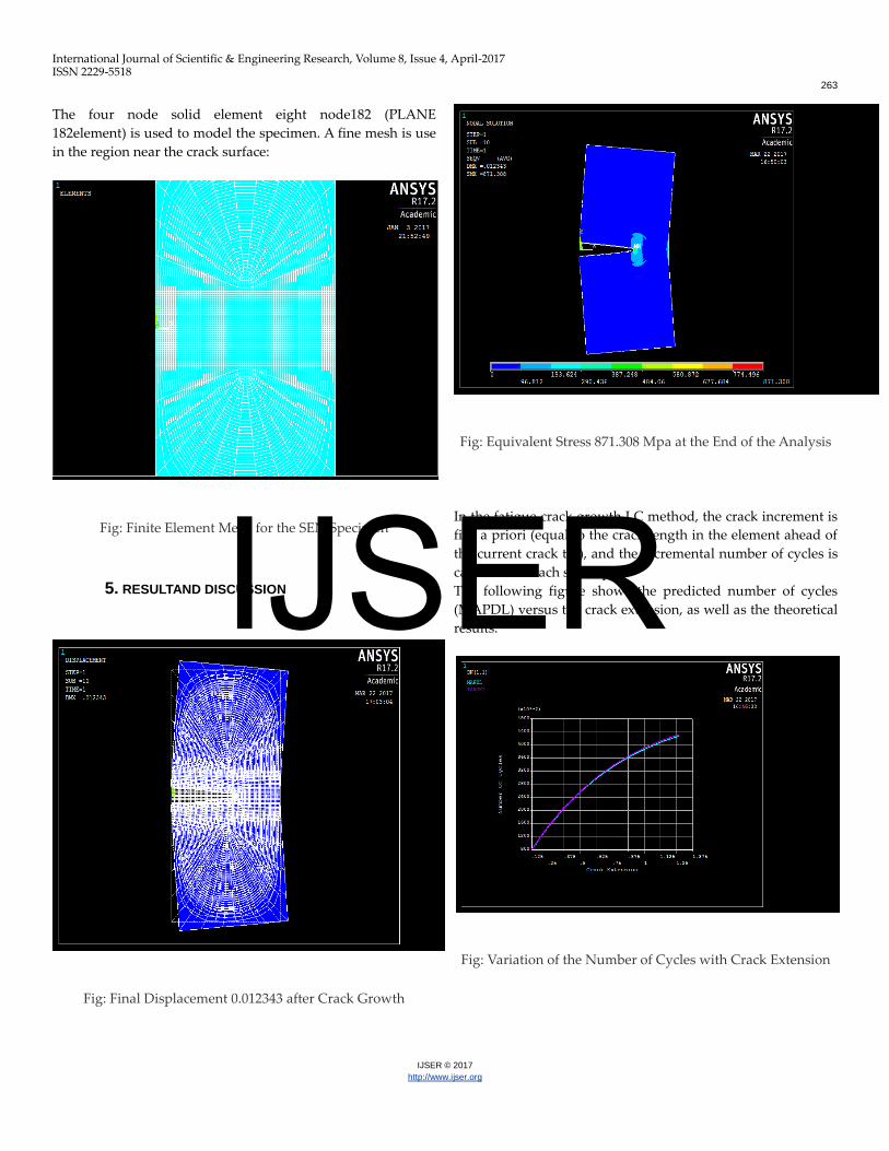
The four node solid element eight node182 (PLANE
182element) is used to model the specimen. A fine mesh is use
in the region near the crack surface:
Fig: Finite Element Mesh for the SEN Specimen
5. RESULTAND DISCUSSION
Fig: Final Displacement 0.012343 after Crack Growth
Fig: Equivalent Stress 871.308 Mpa at the End of the Analysis
In the fatigue crack growth LC method, the crack increment is
fixe a priori (equal to the crack length in the element ahead of
the current crack tip), and the incremental number of cycles is
calculate for each substep.
The following figure shows the predicted number of cycles
(MAPDL) versus the crack extension, as well as the theoretical
results.
Fig: Variation of the Number of Cycles with Crack Extension
IJSER
International Journal of Scientific & Engineering Research, Volume 8, Issue 4, April-2017 ISSN 2229-5518
264
IJSER © 2017
http://www.ijser.org
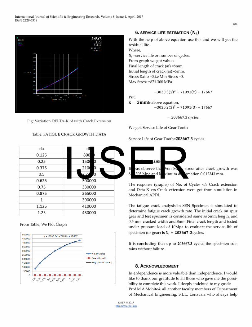
Fig: Variation DELTA-K of with Crack Extension
Table: FATIGUE CRACK GROWTH DATA
From Table, We Plot Graph
6. SERVICE LIFE ESTIMATION (𝐍𝐟) With the help of above equation use this and we will get the
residual life
Where,
Nf =service life or number of cycles.
From graph we got values
Final length of crack (af) =8mm.
Initial length of crack (ai) =5mm.
Stress Ratio =0.i.e Min Stress =0.
Max Stress =871.308 MPa
−3030.3 𝑥 2 + 71091 𝑥 + 17667
Put.
𝐱 = 𝟑𝐦𝐦Inabove equation, −3030.2 3 2 + 71091 3 + 17667
= 203667.3 𝑐𝑦𝑐𝑙𝑒𝑠
We get, Service Life of Gear Tooth
Service Life of Gear Tooth=203667.3 cycles.
7. CONCLUSION
It was observe that Von Mises stress after crack growth was
871.305 Mpa and Maximum deformation 0.012343 mm.
The response (graphs) of No. of Cycles v/s Crack extension
and Deta K v/s Crack extension were got from simulation in
Mechanical APDL.
The fatigue crack analysis in SEN Specimen is simulated to
determine fatigue crack growth rate. The initial crack on spur
gear and test specimen is considered same as 5mm length, and
0.5 mm cracked width and 8mm Final crack length and tested
under pressure load of 10Mpa to evaluate the service life of
specimen (or gear) is Nf = 𝟐𝟎𝟑𝟔𝟔𝟕. 𝟑cycles.
It is concluding that up to 203667.3 cycles the specimen sus-
tains without failure.
8. ACKNOWLEDGMENT
Interdependence is more valuable than independence. I would
like to thank our gratitude to all those who gave me the possi-
bility to complete this work. I deeply indebted to my guide
Prof M A Mohite& all another faculty members of Department
of Mechanical Engineering, S.I.T., Lonavala who always help
da dN
0.125 80000
0.25 150000
0.375 210000
0.5 255000
0.625 300000
0.75 330000
0.875 365000
1 390000
1.125 410000
1.25 430000
IJSER
International Journal of Scientific & Engineering Research, Volume 8, Issue 4, April-2017 ISSN 2229-5518
265
IJSER © 2017
http://www.ijser.org
me, gave proper suggestions and encouraged me at all time
and guided me for writing this paper.
REFERENCES
[1] G.P.Cavallaroa,T.p.wilksa,c.subramaniana,k.n.straffor
da,p.frenchb,J.E Allison, “Bending Fatigue and con-
tact Fatigue characteristic Of Carburized
Gears”surface and coating technology 71(1995)182-
192
[2] ZaigangChna,WanmingZhaia,Yiminshaob,Kaiyun
Wanga,GuohuaSunc,“Analytical model for mesh
stiffness calculation of spur gear pair with non-
uniformly distributed tooth root crack”, Engineering
Failure analysis xxx(2016)xxx-xxx
[3] DENG Song,HUALin,HAN Xing-hui,HUANG Song,
“Finite element analysis of contact fatigue and bend-
ing fatigue of a theoretical assembling straight bevel
gear pair”
[4] J.Kramberger,M.Srami,S.Glodez,J.Flasker,I.Potre,“Co
mputational model for the analysis of bending fa-
tigue in gears”, computers and structures
82(2004)2261-2269.
[5] SrdanPodrug,SreckoGlodez-
DamirJelaska,”Numerical modeling of crack in a gear
tooth root”, Strojniskivestnik-Journal of Mechanical
engineering 57(2011)7-8,579-586.
[6] Yogesh Pandya ,AnandParey,“Simulation of crack
propagation in spur gear tooth for different gear pa-
rameter and its influences on mesh stiff-
ness”,Engineering Fatigue Analysis 30(2013)124-137
[7] WennianYua,YiminShaob,ChrisK.Mechefske, “The ef-
fect of spur gear tooth spatial crack propagation on
gear mesh stiffness”, Engineering Failure Analy-
sis54(2015)103-119.
IJSER