Embed Size (px)
Citation preview

trafo modern
Technical JV with
LEADERSHIP IN TRANSFORMATION
MAGNETICS MAGNETICSTransformers & InductorsTransformers & Inductors
®
Power Ratings up to 1000kVA Customised Magnetics Complying to International Standards

APPLICATION AREAS...
Renewable and Non-renewable Energy (Wind, Solar & UPS)
8 PFC Chokes
Input and Output Filter Chokes 8
Inverter Isolation & Rectier Input 8
Auxiliary & Integrated Transformers8
Converter Duty Transformers8
Air Core Reactors8
8 Power Supply Auto-Transformers
Battery Charging Transformers8
DC Chokes 8
Hotel Load Converter Chokes 8
Traction/Railway
8 Input / Output / Line Filter Chokes
Converter Duty Transformers8
Low loss Multi Winding Tx & Chokes8
Phase Shift Transformers8
Drives Applications
8 Isolation Transformers
Control Transformers 8
Machine Tools
Special Applications 8 Transformers for Medical applications etc.
Intermediate Transformers8
Marine Applications 8 Dry type Transformers and Inductors
Water Cooled Transformers and Inductors8
8 Multi-taping Potential Transformers
Power Transformers8
K rated Transformers8
Detuned Reactors8
RL Load Reactors 8
Industrial Applications
1
VisionOur Vision is to be a Global
Electrical Solutions Company,
most admired for its people,
performance and values
MissionOur Mission is to build on our experience in product
excellence and technology / innovation to provide the
highest quality and most reliable electrical products and
services to our customers
SALZER Trafomodern - Technical JVIn 2015, Salzer Electronics entered into a Technical Joint Venture with Trafomodern, Austria. The
Design and Process Technology is supported by Trafomodern to manufacture energy efcient
Transformers, Inductors and Chokes.
Trafomodern - in Briefl Established in 1945 and located in Hornstein, Austria
l Has achieved market leadership in the course of 70-years
l An ISO 9001, ISO 14001, UL, CSA and ATEX approved company
l Trafomodern, Austria is a market leader for Inductive winding components and are exporting to
many countries worldwide
l Established in 1985, headquartered in Coimbatore, South India
l With a wide range of products catering to Industrial, Building and Construction, Energy Management and Automotive Segments
l Five Factories with International afliations
l Technology Leadership through global alliances and innovations
l International Product Approvals such as CSA, UL, S-mark, CB certication, CE and RoHS- compliance
l India's Leader in Rotary Switches and Wiring Ducts
l Wide distribution network in India and exports to over 50 countries
SALZER, in Brief

l 1 Phase and 3 Phase Designs
l 5 Magnetic Limb Designs
l T ransformer with Integrated Choke
l Air core Construction Design
l Multiple Tap output Construction
l Parts with Enclosure Design
by ConstructionProduct RangeMagnetic Parts Capabilities
l Transformer (3 Phase and 1 Phase) upto 1000kVA, 690V
l Inductor (3 Phase and 1 Phase) upto 1 MVAr, 2500A-Max
Current Rating
l DC Chokes
l Special Products
l OVDT - Open Ventilated Dry type Transformers - 11kV / 433V,
Class-F/H-upto 400kVA
l Water cooled Reactors
Product Range by Function - Transformers / Inductorsl Step-up and Step-down
l Isolation Transformers
l Control Transformers
l Lighting Transformers
l Auto / Multi taping Transformers
l Buck boost Transformers
l Power Supplying Units
l K-Rated Transformers
l Special applications
l Input and Output Chokes
l Power Factor Correction (PFC)
l Boost Choke
l Harmonics / Ripple Filtering
l DC Chokes
l Chokes for Drives application
l Balancing Reactor
l Power Smoothening Reactor
l Detuned Reactor
l RL-Load Reactor
2
Salzer has design technology capable to develop customised
transformer, Inductors and integrated/ assembled magnetics as
per the required specication.
Our engineering is strengthened with skills of analysing the
important parameters such as Temperature/cooling, Shock and
Vibration, Short circuit withstand capability which enables us to
offer robust and reliable products.
Our design process is continuously improved with engineering
skills and innovative technology by in-house research and
development.
We design product in compliance with directives such as
IS, IEC, UL, EN, ANSI/CS, RoHS and CE. Our Magnetics are
designed to meet High Efciency, Low Noise, Low Losses, Good
dielectric withstand capabilities with proven insulation system
0up to 220 C.
Salzer Electronics engineering is providing cost effective
solution and with value engineering optimising the cost
effectiveness.
Engineering
3

8 Factory infrastructure with dust-free and
clean environment
8 State of the art winding machines
8 sPrecise Lamination cutting machine
8 Customised xtures to achieve precise
calibrated inductance
8 Automated Vacuum Pressurised
Impregnation plant (VPI)
8 SCADA enabled test bench
8 Well designed process control system
Manufacturing
4
Quality & Testing
The Routine test such as:
8 Winding resistance test
No load loss and current test8
Load Loss test and impedance test8
Turns ratio Test 8
Separate source voltage test (Hipot)8
Insulation Resistance (IR) test8
DVDF/IOVT Test 8
Inductance test8
Losses test 8
Noise level Test8
Thermal Heat run (Type Test)�������l��
PD (Type Test)�������l��
Shock & Vibration (Type Test)�������l��
Lightning Impulse Test (Type Test)�������l��
Zero-Defect is our aim. We maintain reliable standards in the
quality of our product line. The Magnetics produced in Salzer are
tested for various quality parameters. As the Magnetic parts are a
critical category the basic validation of design, safety,
performance and reliability are tested.
Salzer has full-edged in-house Automated Testing Laboratory to
conduct Routine Test for Transformer and Inductors as per IEC/IS
Standards.
5

RENEWABLE ENERGY / WIND & SOLARInductor of single phase and 3 Phase for high frequency lter
application. These chokes are designed to specied harmonics
to maximize the efciency by limiting the losses and
temperature by using high grade magnetic lamination with low
magnetostriction, eddy current, and hysteresis losses and
calibrated inductance. Salzer compact design, Insulation class
and vacuumed pressurized impregnation makes it maintenance-
free for a long service life. The chokes are used in onshore and
offshore installations.
In Solar Energy application : 3-phase Sine wave lter inductor
used at IGBT output of Inverter and connecting to grid
transformer for Current Harmonics Filtering and smoothing
application.
Auxiliary isolation transformers for Solar Energy application
which is connected to Grid and supplying auxiliary power to
Solar Central Inverter accessories like pump, Heat exchanger,
cooling fans, cabinet fans, Heaters, SMPS etc. The Grid is
connected to output of IGBT bases inverter. Hence transformer
will be designed to customised impedance to limit lesser
percentage of Voltage THD (Total Harmonic Distortion) at
secondary side. Salzer has also Step up Grid transformer with
multiple input winding and single output upto 12KV voltage
class.
6
REN
EWA
BLE
EN
ERG
Y /
WIN
D &
SO
LAR
Prod
ucts
& A
pplic
atio
ns
3Phase sine wave lter inductor is
used at output of IGBT based
inverters (Solar & Wind inverter)
Copper / Aluminium wound
Current: upto 2500A
Inductance: as per customer spec0Insulation Class: upto 220 C
3Phase sine wave filter Inductor
3Phase Isolation / Auto Transformer
1Phase sine wave filter Inductor
1Phase sine wave lter inductor is
used at output of IGBT based
inverters (Solar & Wind inverter)
Copper / Aluminium wound
Current: upto 2500A
Inductance: as per customer spec0Insulation Class: upto 220 C
3Phase Water Cooled Inductor
3Phase water cooled inductor is
used in Solar panel and Windmills
Copper / Aluminium wound
Current: upto 2500A
Inductance: as per customer spec0Insulation Class: upto 220 C
Water ow: as per customer spec
3Phase Isolation / Auto Transformers
connected to the grid providing
Auxiliary power supply to
accessories inverter panel
Copper / Aluminium wound
Rating: upto 100KVA0Insulation Class: upto 220 C
7

Salzer provides a complete range of magnetics solutions for
UPS applications. PFC Inverter Chokes, Battery Converter
Choke, Boost Converter Filter Inductor, Smoothing choke,
saturating reactor, Air core inductor, Isolation Transformer,
Control Transformer, Matching Transformer, Inverter Isolation,
Rectier Input, Auxiliary, Integrated and auto transformer.
The boost converter lter inductor will be on the input side,
which provides a smooth, continuous, input current waveform
as opposed to the discontinuous input current of the buck or
buck-boost topology. The continuous input current is much
easier to lter.
The PFC/INV Chokes designed for switching frequency up to
8kHz with high grade magnetic lamination is economic and
more stable inductance with respect to temperature rise.
Salzer offers these chokes with powder or ferrite core.
Salzer can provide design and manufacturing solution for UPS
Transformer integrated with Ls for compact solution in both
core type and shell type. We also manufacture Zig-Zag
connected winding transformer, open delta winding, multi-
winding transformer for 6 and 12 pulse converter for PWM wave
application.
UNINTERRUPTED POWER SUPPLY (UPS)
8
Prod
ucts
& A
pplic
atio
nsU
NIN
TE
RR
UP
TE
D P
OW
ER
SU
PP
LY (U
PS)
Transformers
Rectied input Transformerl
Inverter output Transformer / Isolation / l
Integrated Transformer
Dry type Transformer
Rated frequency
Reference standard
Number of Phase
Cooling
Type
Vector group
Magnetizing current
Impedance
Losses
Temperature rise
Rating
Voltage
Insulation Class
50Hz / 60Hz
EN/IEC 600076 - 11
1 PH / 3 PH
upto 220°C
upto 800KVA
upto 750V
AN/AF
Core / Shell type
as per customer spec
as per customer spec
as per customer spec
as per customer spec
as per customer spec
9

TRACTION / RAILWAYSalzer produces Auxiliary Transformers, Power Supply
Transformers, DC Reactors, Step-up chopper - Inductor, Three
phase output choke and Single phase Battery Charger
Transformer for the Traction/ Railway Application. The
Auxiliary transformers are used for lighting purposes, heating
the train wagons or for producing single-phase auxiliary for the
safety systems supply or the substation's supply.
Step-up Chopper - Inductor, step-up Chopper in a battery
charger, which is used for the adjustment of the output voltage
for optimised charging of the traction vehicle battery and
supply of the battery load circuits.
3 phase output choke: This Choke is used to lter the current
harmonics produced by the PWM of three phase inverter.
Range comprises of Battery Charging Converter Transformer,
Field Transformer, Power Supply Transformer for Passenger
Area, Line Air Choke to DC Link, Boost converter chokes for
auxiliary inverters, Power Supply Auto transformer for fan for
climate regulating applications. Salzer uses special raw
materials for Railway applications for better UL ammability
and High Insulation class additional coat varnish etc.
Since Railway application parts are long service magnetics,
Salzer takes utmost care while designing: Insulation
coordination, Cooling, Environmental conditions (Climate,
Pollution / Humidity, Vibration / Mechanical shocks).
Validation type tests are conducted on the samples in order to
ensure reliability in the long run.
10
TR
AC
TIO
N /
RA
ILW
AYP
rod
uct
s &
Ap
pli
cati
ons
Power supply Transformer Step down / Step up application
Mounted IndoorRating : 100 KVA maxNominal Voltage: 750VmaxPollution degree: PD4Insulation temp Req 220°CStandard: EN/IEC 60076,
BS/EN 60310, EN/IEC 60077 -1
Traction Transformers
Battery & Field Transformer:
Single-phase Transformer with
secondary center tapped for
rectier input
Rating: 500 KVA maxNominal Voltage 750 V maxOperating frequency 600HzInsulation temp Req 220°CPollution degree: PD4Standard: EN/IEC 60076,
BS/EN 60310, EN/IEC 60077 -1
DC Reactor - Filter application for
Battery Charging CircuitInductance : as per customer specCurrent : 1000Adc maxNominal Voltage: 3000VmaxPollution degree: PD4Insulation temp Req 220°CStandard: EN/IEC 60076,
BS/EN 60310, EN/IEC 60077 -1
DC Reactor
Power supply transformer
Power supply transformer
Power supply auto transformer
Boost Converter Chokes
Power supply Transformer for
Passenger Area & Mounted Under FloorRating : 100 KVA maxNominal Voltage: 750VmaxPollution degree: PD4Insulation temp Req 220°CStandard: EN/IEC 60076,
BS/EN 60310, EN/IEC 60077 -1
Line Air Choke to DC linkMounted Under FloorVoltage: 750VDC Current: upto 500 AmpsInductance : As per customer specFlammable class UL94/V0Standard: EN/IEC 60076,
BS/EN 60310, EN/IEC 60077 -1
Air core Inductor
Iron Core Boost Converter Chokes
for Auxiliary Inverters Inductance : as per customer specCurrent : 1000Adc maxNominal Voltage: 3000VmaxPollution degree: PD4Insulation temp Req 220°CStandard: EN/IEC 60076,
BS/EN 60310, EN/IEC 60077 -1
Power supply Transformer for Fan,
Climate regulating & Control Rating : 100 KVA maxNominal Voltage: 750VmaxPollution degree: PD4Insulation temp Req 220°CStandard: EN/IEC 60076,
BS/EN 60310, EN/IEC 60077 -1
11

Products & ApplicationsMarine
Salzer has vast experience in designing and manufacturing
magnetics for Marine applications. In Marine application,
Salzer offers Transformer and Reactors in VPI version and
Water cooled version. Applications include Line reactors and
special reactors, Isolation Transformer, Start up
Transformers etc.
The key factors for marine magnetic products are low foot
print and weight but with highest possible efciency. Salzer
is capable of providing solutions for these applications in
both water cooled type and air cooled type meeting those key
factors.
Our transformers and inductors for marine applications are
made with special insulating materials to ensure longer life
in saline atmosphere. In order to ensure product reliability,
Salzer can support for environmental type tests including
salt mist test, Our Products are meeting EMI and EMC
Requirements.
Single or multi secondary windings, thermal protection for
the best temperature control are amongst these
transformers features. The features are optimised design
based on specic harmonic loads, compact dimensions,
lightweight materials, designs can be adapted to the
dimensional constraints of any installation, specic cooling
enclosure, rated power: max 1000 KVA.
12
Mar
ine
Pro
du
cts
& A
pp
lica
tion
s
Rating: upto 500kVA
Rated frequency : 50Hz / 60Hz
Nominal Voltage: upto 750V
Cooling: AN, WF
Reference standard : EN / IEC 60076 - 11
Water force : As per customer spec.
Total Losses : As per customer spec.
Magnetizing current: As per customer spec.
Impedance : As per customer spec.
Temperature rise: As per customer spec.
Aluminium or Copper wound0Insulation Class upto 180 C
Water cooled Transformer Water cooled Reactor
Rating: upto 2500A
Rated frequency : 50Hz / 60Hz
Switching Frequency: upto 10KHz
Cooling: AN, WF
Reference standard : EN / IEC 60076 - 6
Water force : As per customer spec.
Total Losses : As per customer spec.
Inductance : As per customer spec.
Temperature rise: As per customer spec.
Aluminium or Copper wound0Insulation Class upto 180 C
13

Salzer offers Multi-tapping Potential Transformers, OVDT, Multi
winding transformer for converter / furnace application and K-
rated transformer for Industrial application
up to 12kV class
8 Multiple Winding Transformers can also be used to provide
either step-up, step-down or a combination of both between the
various windings. In fact, a multiple winding transformer can have
several secondary windings on the same core with each one
providing a different voltage or current level output.
8 Multi-coil, or multi-winding transformer will be designed for
required vector group as per customer requirement. Also we can
design with customized Short-circuit impedance. Multiple winding
transformers can be either a single-phase transformer or a three-
phase transformer.
The application of a K-rated transformer is used where ever non-
linear loads are present. Prime uses would be in factory
automation, computer rooms, and ofce buildings due to high
harmonic content in these loads. K-rated transformer isolates or
avoiding transferring of harmonics to main power supply in
network. Our K-rated transformers designed to dissipate the
additional heat generated by harmonics or non linear load.
K-rated transformers are sized appropriately to handle this
additional heat and tested according to UL standards. The way a
K-rated transformer works is it uses a double sized neutral
conductor and either change the geometry of their conductors or
use multiple conductors for the coils. Quality transformers are
manufactured with high grade silicon steel, copper windings, and
extra air ducts.
Harmonics: It is a value used to determine how much harmonic
current a transformer can handle without exceeding its maximum
temperature rise level.
Industrial Application
14
The Detuned Reactors are used in the Circuit to protect the Capacitor. In other words we can say to attain better life of Capacitors. The main application of this Reactors is to filter the Harmonics. Salzer designs have the following advantages - High Quality Raw Materials, Low Noise Level, Smaller in Size and Better total Losses.
Note: The below mentioned ratings are Salzer standard design version. We offer custom designs based on requirements.
IEC 60289, IS 5553
440 V
50Hz
1.05 Un Continously, 1.1 Un for 8 hours
1.4 In Continously
1
IP 00050 C
Copper / Aluminium
Class H0Thermal switch ( NC type, 165 C )
5.67% , 7% , 14 %
U3 = 0.5 % Ur ( Duty cycle 100%)
U5 = 6.0 % Ur ( Duty cycle 100%)
U7 = 5.0 % Ur ( Duty cycle 100%)
U11 = 3.5 % Ur ( Duty cycle 100%)
U13 = 3.0 % Ur ( Duty cycle 100%)
U17 = 2.0 % Ur ( Duty cycle 100%)
U19 = 1.5 % Ur ( Duty cycle 100%)
U23 = 1.5 % Ur ( Duty cycle 100%)
U25 = 1.5 % Ur ( Duty cycle 100%)
I1 = 1.06 Ir
Ref. Standard
Rated Voltage
Rated Frequency
Max. Permissible Operating Voltage
Max. Permissible Operating current ( Linearity )
Duty cycle
Class Of Protection
Ambient Temperature
Winding Material
Class of insulation
Thermal protection
Detuning
Harmonics Limit
Fundamental Current
Detuned Reactors
7%,14%,5.67% Impedance in Copper / Aluminium wound and Air Natural (AN) Cooling
15
*Los
ses
show
n a
re o
ur
sta
nd
ard
des
ign
ver
sion
. We
can
des
ign
an
y ot
her
les
ser
loss
es a
lso
ba
sed
on
cu
stom
er r
equ
irem
ent.
(A) Electrical Data (7% Impedance)
S.No
1
2
3
4
5
6
7
8
9
KVAR Un (V) F1 (Hz) %pIn or I1[A]
Irms or Ieff [A]
Isat [A] Isat[A]/I1
Inductance[mH] *Total Losses F-Eqt. (Hz)
5
10
12.5
15
20
25
50
75
100
440
440
440
440
440
440
440
440
440
50
50
50
50
50
50
50
50
50
7
7
7
7
7
7
7
7
7
6.60
13.10
16.40
19.70
26.20
32.80
65.60
98.40
131.20
7.40
14.90
18.60
22.30
29.80
37.20
74.40
111.60
148.80
11.88
23.58
29.52
35.46
47.16
59.04
118.08
177.12
236.16
1.80
1.80
1.80
1.80
1.80
1.80
1.80
1.80
1.80
9.280
4.640
3.710
3.090
2.320
1.860
0.928
0.619
0.464
55
75
90
100
135
160
265
350
400
85
85
85
85
85
85
85
85
85
TM32-0030-00
TM32-0031-00
TM32-0032-00
TM32-0033-00
TM32-0034-00
TM32-0035-00
TM32-0036-00
TM32-0037-00
TM32-0038-00
Salzer Part No.Copper Ver.
(B) Electrical Data (14% Impedance)
S.No
1
2
3
4
5
6
7
8
9
KVAR Un (V) F1 (Hz) %pIn or I1[A]
Irms or Ieff [A]
Isat [A] Isat[A]/I1
Inductance[mH] *Total Losses
TM32-0039-00
TM32-0040-00
TM32-0041-00
TM32-0042-00
TM32-0043-00
TM32-0044-00
TM32-0045-00
TM32-0046-00
TM32-0047-00
5
10
12.5
15
20
25
50
75
100
440
440
440
440
440
440
440
440
440
50
50
50
50
50
50
50
50
50
14
14
14
14
14
14
14
14
14
6.60
13.10
16.40
19.70
26.20
32.80
65.60
98.40
131.20
7.00
14.10
17.50
22.10
28.00
35.00
70.00
105.10
140.10
9.90
19.65
24.60
29.55
39.30
49.20
98.40
147.60
196.80
1.50
1.50
1.50
1.50
1.50
1.50
1.50
1.50
1.50
20.060
10.030
8.030
6.690
5.020
4.010
2.000
1.340
1.000
60
95
100
115
155
190
330
415
450
52
52
52
52
52
52
52
52
52
(C ) Electrical Data (5.67% Impedance)
S.No
1
2
3
4
5
6
7
8
9
KVAR Un (V) F1 (Hz) %pIn or I1[A]
Irms or Ieff [A]
Isat [A] Isat[A]/I1
Inductance[mH]
TM32-0048-00
TM32-0049-00
TM32-0050-00
TM32-0051-00
TM32-0052-00
TM32-0053-00
TM32-0054-00
TM32-0055-00
TM32-0056-00
5
10
12.5
15
20
25
50
75
100
440
440
440
440
440
440
440
440
440
50
50
50
50
50
50
50
50
50
5.67
5.67
5.67
5.67
5.67
5.67
5.67
5.67
5.67
6.6
13.1
16.4
19.7
26.2
32.8
65.6
98.4
131.2
8.8
17.6
20.9
25.1
33.5
41.8
83.63
125.4
167.3
15.2
30.1
37.7
45.3
60.3
75.4
150.9
226.3
301.8
2.3
2.3
2.3
2.3
2.3
2.3
2.3
2.3
2.3
7.41
3.7
2.96
2.47
1.85
1.48
0.741
0.494
0.37
60
95
100
125
165
200
340
425
480
115
115
115
115
115
115
115
115
115
TM32-0002-00
TM32-0003-00
TM32-0004-00
TM32-0005-00
TM32-0006-00
TM32-0007-00
TM32-0008-00
TM32-0009-00
TM32-0010-00
Salzer Part No.Aluminium Ver.
TM32-0012-00
TM32-0013-00
TM32-0014-00
TM32-0015-00
TM32-0016-00
TM32-0017-00
TM32-0018-00
TM32-0019-00
TM32-0020-00
Salzer Part No.Copper Ver.
Salzer Part No.Aluminium Ver.
TM32-0021-00
TM32-0022-00
TM32-0023-00
TM32-0024-00
TM32-0025-00
TM32-0026-00
TM32-0027-00
TM32-0028-00
TM32-0029-00
Salzer Part No.Copper Ver.
Salzer Part No.Aluminium Ver.
16
F-Eqt. (Hz)
*Total Losses F-Eqt. (Hz)
(A) Mechanical Data (7% Impedance)
S.No
1
2
3
4
5
6
7
8
9
TM32-0002-00
TM32-0003-00
TM32-0004-00
TM32-0005-00
TM32-0006-00
TM32-0007-00
TM32-0008-00
TM32-0009-00
TM32-0010-00
5
10
12.5
15
20
25
50
75
100
225
225
225
225
250
270
270
290
360
140
145
150
160
150
160
160
210
205
165
170
180
180
210
250
310
310
340
203
203
203
203
150
150
150
180
180
72
92
92
105
110
110
110
145
145
8 X 12
8 X 12
8 X 12
8 X 12
12 X 20
12 X 20
12 X 20
12 X 20
12 X 20
225
225
225
225
250
270
270
290
360
94
115
115
125
140
140
140
185
185
6
9
11
13
16
19
29
38
51
Salzer Part No. KVAR L (mm) B(mm) H(mm) n1 (mm ) n2 (mm ) Slot (mm) b (mm) d (mm)Part
Weight (Kg)
E1
E1
E1
E1
E2
E2
E2
E3
E3
Enclosure(Optional)
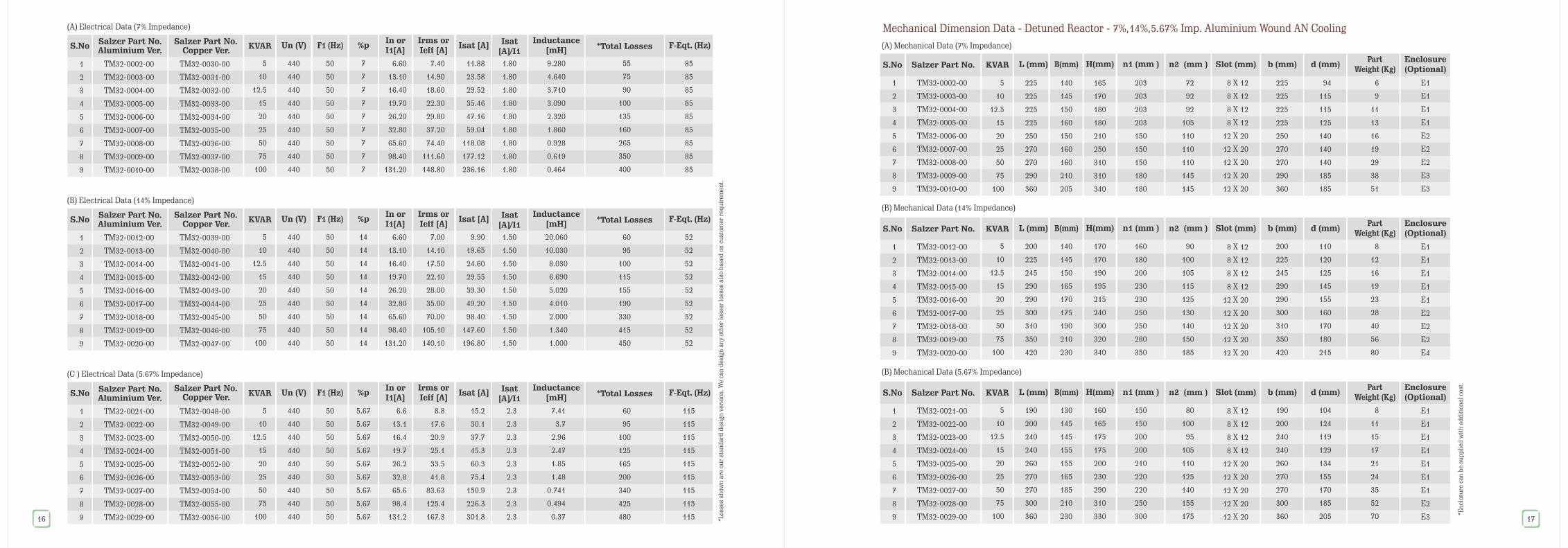
Mechanical Dimension Data - Detuned Reactor - 7%,14%,5.67% Imp. Aluminium Wound AN Cooling
(B) Mechanical Data (14% Impedance)
S.No
1
2
3
4
5
6
7
8
9
Salzer Part No. KVAR L (mm) B(mm) H(mm) n1 (mm ) n2 (mm ) Slot (mm) b (mm) d (mm)Part
Weight (Kg)Enclosure(Optional)
TM32-0012-00
TM32-0013-00
TM32-0014-00
TM32-0015-00
TM32-0016-00
TM32-0017-00
TM32-0018-00
TM32-0019-00
TM32-0020-00
5
10
12.5
15
20
25
50
75
100
200
225
245
290
290
300
310
350
420
170
170
190
195
215
240
300
320
340
140
145
150
165
170
175
190
210
230
160
180
200
230
230
250
250
280
350
90
100
105
115
125
130
140
150
185
8 X 12
8 X 12
8 X 12
8 X 12
12 X 20
12 X 20
12 X 20
12 X 20
12 X 20
200
225
245
290
290
300
310
350
420
110
120
125
145
155
160
170
180
215
8
12
16
19
23
28
40
56
80
E1
E1
E1
E1
E1
E2
E2
E2
E4
(B) Mechanical Data (5.67% Impedance)
S.No
1
2
3
4
5
6
7
8
9
Salzer Part No. KVAR L (mm) B(mm) H(mm) n1 (mm ) n2 (mm ) Slot (mm) b (mm) d (mm)Part
Weight (Kg)Enclosure(Optional)
TM32-0021-00
TM32-0022-00
TM32-0023-00
TM32-0024-00
TM32-0025-00
TM32-0026-00
TM32-0027-00
TM32-0028-00
TM32-0029-00
5
10
12.5
15
20
25
50
75
100
190
200
240
240
260
270
270
300
360
130
145
145
155
155
165
185
210
230
160
165
175
175
200
230
290
310
330
150
150
200
200
210
220
220
250
300
80
100
95
105
110
125
140
155
175
8 X 12
8 X 12
8 X 12
8 X 12
12 X 20
12 X 20
12 X 20
12 X 20
12 X 20
190
200
240
240
260
270
270
300
360
104
124
119
129
134
155
170
185
205
8
11
15
17
21
24
35
52
70
E1
E1
E1
E1
E1
E1
E1
E2
E3
*En
clos
ure
ca
n b
e su
pp
lied
wit
h a
dd
itio
na
l co
st.
17

(A) Mechanical Data (7% Impedance)
(B) Mechanical Data (14% Impedance)
(B) Mechanical Data (5.67% Impedance)
S.No
S.No
S.No
1
2
3
4
5
6
7
8
9
1
2
3
4
5
6
7
8
9
1
2
3
4
5
6
7
8
9
Salzer Part No.
Salzer Part No.
Salzer Part No.
KVAR
KVAR
KVAR
L (mm)
L (mm)
L (mm)
B(mm)
B(mm)
B(mm)
H(mm)
H(mm)
H(mm)
n1 (mm )
n1 (mm )
n1 (mm )
n2 (mm )
n2 (mm )
n2 (mm )
Slot (mm)
Slot (mm)
Slot (mm)
b (mm)
b (mm)
b (mm)
d (mm)
d (mm)
d (mm)
Part Weight (Kg)
Part Weight (Kg)
Part Weight (Kg)
Enclosure(Optional)
Enclosure(Optional)
Enclosure(Optional)
Mechanical Dimension Data - Detuned Reactor - 7%,14%,5.67% Imp. Copper Wound AN Cooling
*En
clos
ure
ca
n b
e su
pp
lied
wit
h a
dd
itio
na
l co
st.
TM32-0030-00
TM32-0031-00
TM32-0032-00
TM32-0033-00
TM32-0034-00
TM32-0035-00
TM32-0036-00
TM32-0037-00
TM32-0038-00
5
10
12.5
15
20
25
50
75
100
215
215
215
215
230
250
250
270
340
140
145
150
160
150
160
160
210
205
165
170
180
180
210
250
310
310
340
203
203
203
203
150
150
150
180
180
72
92
92
105
110
110
110
145
145
8 X 12
8 X 12
8 X 12
8 X 12
12 X 20
12 X 20
12 X 20
12 X 20
12 X 20
215
215
215
215
230
250
250
270
340
94
115
115
125
140
140
140
185
185
8
12
15
17
21
25
38
50
67
E1
E1
E1
E1
E1
E1
E1
E1
E2
TM32-0039-00
TM32-0040-00
TM32-0041-00
TM32-0042-00
TM32-0043-00
TM32-0044-00
TM32-0045-00
TM32-0046-00
TM32-0047-00
5
10
12.5
15
20
25
50
75
100
200
225
245
290
290
300
310
350
420
140
145
150
165
170
175
190
210
230
170
170
190
195
215
240
300
320
340
160
180
200
230
230
250
250
280
350
90
100
105
115
125
130
140
150
185
8 X 12
8 X 12
8 X 12
8 X 12
12 X 20
12 X 20
12 X 20
12 X 20
12 X 20
200
225
245
290
290
300
310
350
420
110
120
125
145
155
160
170
180
215
11
16
21
25
30
37
52
73
104
E1
E1
E1
E2
E2
E2
E2
E3
E4
TM32-0048-00
TM32-0049-00
TM32-0050-00
TM32-0051-00
TM32-0052-00
TM32-0053-00
TM32-0054-00
TM32-0055-00
TM32-0056-00
5
10
12.5
15
20
25
50
75
100
190
200
240
240
260
270
270
300
360
130
145
145
155
155
165
185
210
230
160
165
175
175
200
230
290
310
330
150
150
200
200
210
220
220
250
300
80
100
95
105
110
125
140
155
175
8 X 12
8 X 12
8 X 12
8 X 12
12 X 20
12 X 20
12 X 20
12 X 20
12 X 20
190
200
240
240
260
270
270
300
360
104
124
119
129
134
155
170
185
205
10
15
20
23
27
32
46
68
91
E1
E1
E1
E1
E1
E1
E1
E2
E318
Metal enclosure with Powder Coating and IP 31 with 2 No. SS Gland plate, 2 No.Lifting
S.No
1
2
3
4
Enclosure
E1
E2
E3
E4
L1 (mm)
350
400
460
540
B1 (mm)
325
325
375
375
H1 (mm)
435
570
600
600
Wt.(Kg)
16
19
25
25
Enclosure dimensions are tentative
Customised dimensions will be shared during OA
19
Thermal Switch (TS) for Over temp. Trip
NC type Thermal Switch
TS 1
U-PH
1
AA
1U 1V 1W
2U 2V 2W
SCHEMATIC DIAGRAM:
1U
2U
1V
2V
1W
2W

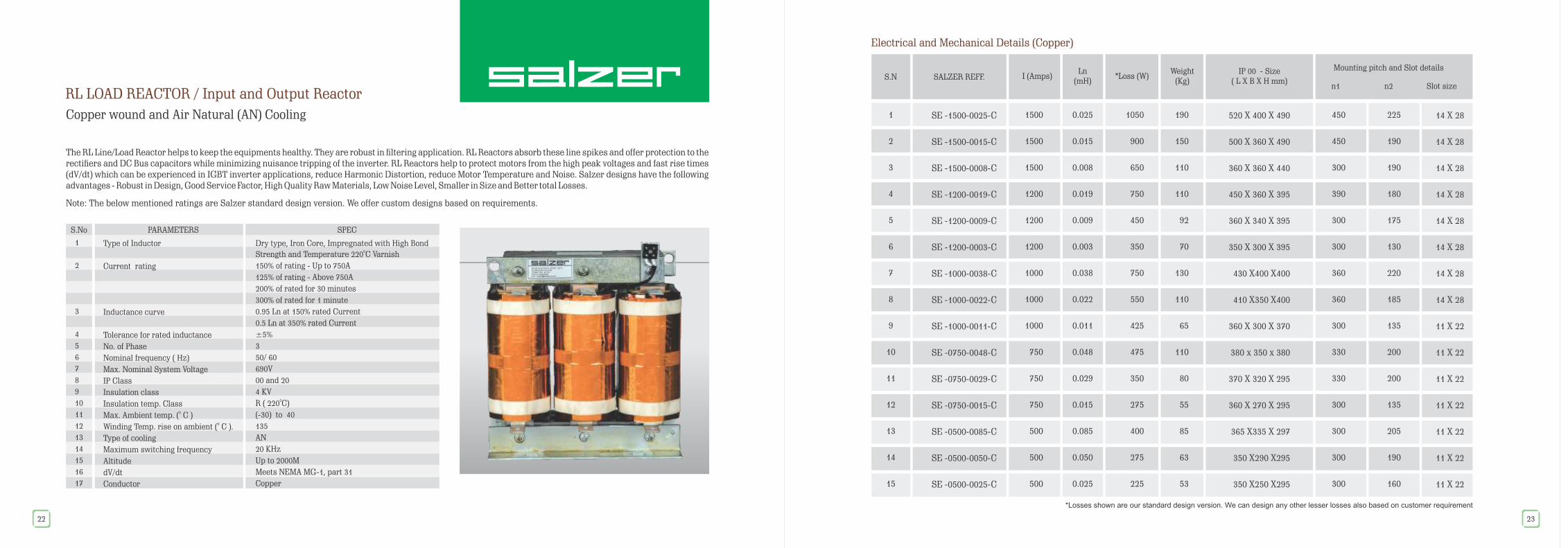
The RL Line/Load Reactor helps to keep the equipments healthy. They are robust in ltering application. RL Reactors absorb these line spikes and offer protection to the rectiers and DC Bus capacitors while minimizing nuisance tripping of the inverter. RL Reactors help to protect motors from the high peak voltages and fast rise times (dV/dt) which can be experienced in IGBT inverter applications, reduce Harmonic Distortion, reduce Motor Temperature and Noise. Salzer designs have the following advantages - Robust in Design, Good Service Factor, High Quality Raw Materials, Low Noise Level, Smaller in Size and Better total Losses.
Note: The below mentioned ratings are Salzer standard design version. We offer custom designs based on requirements.
RL LOAD REACTOR / Input and Output Reactor
Aluminium wound and Air Natural (AN) Cooling
S.No PARAMETERS SPEC
Type of Inductor
Current rating
Inductance curve
Tolerance for rated inductance
No. of Phase
Nominal frequency ( Hz)
Max. Nominal System Voltage
IP Class
Insulation class
Insulation temp. Class
Max. Ambient temp. ( C ) 0
Winding Temp. rise on ambient ( C ). 0
Type of cooling
Maximum switching frequency
Altitude
dV/dt
Conductor
Dry type, Iron Core, Impregnated with High Bond 0Strength and Temperature 220 C Varnish
150% of rating - Up to 750A
125% of rating - Above 750A
200% of rated for 30 minutes
300% of rated for 1 minute
0.95 Ln at 150% rated Current
0.5 Ln at 350% rated Current
±5%
3
50/ 60
690V
00 and 20
4 KV 0R ( 220 C)
(-30) to 40
135
AN
20 KHz
Up to 2000M
Meets NEMA MG-1, part 31
Aluminium
1
2
3
4
5
6
7
8
9
10
11
12
13
14
15
16
17
20
Electrical and Mechanical Details (Aluminium)
S.N I (Amps) *Loss (W)Weight
(Kg)IP 00 - Size
( L X B X H mm)n1 n2 Slot size
Mounting pitch and Slot detailsSALZER REFF.
Ln (mH)
1
2
3
4
5
6
7
8
9
10
11
12
13
14
15
RL -1500-0025-AL
RL -1500-0015-AL
RL -1500-0008-AL
RL -1200-0019-AL
RL -1200-0009-AL
RL -1200-0003-AL
RL -1000-0038-AL
RL -1000-0022-AL
RL -1000-0011-AL
RL -0750-0048-AL
RL -0750-0029-AL
RL -0750-0015-AL
RL -0500-0085-AL
RL -0500-0050-AL
RL -0500-0025-AL
1500
1500
1500
1200
1200
1200
1000
1000
1000
750
750
750
500
500
500
0.025
0.015
0.008
0.019
0.009
0.003
0.038
0.022
0.011
0.048
0.029
0.015
0.085
0.050
0.025
1050
900
650
700
400
425
840
600
450
475
370
270
350
260
200
175
125
80
110
70
50
105
80
50
95
68
49
68
52
38
500 X 370 X 620
500 X 320 X 620
385 X 310 X 500
430 X 330 X 500
385 X 280 X 500
360 X 240 X 420
460 X360 X430
430 X300 X430
360 X 280 X 370
440 x 340 x 430
390 X 300 X 380
360 X 260 X 370
430 X325 X 330
400 X270 X320
350 X240 X300
430
430
300
360
300
300
360
360
300
330
330
300
330
330
300
210
155
150
165
140
130
205
170
150
220
190
140
200
150
125
14 X 28
14 X 28
11 X 22
11 X 22
11 X 22
11 X 22
14 X 28
11 X 22
11 X 22
14 X 28
11 X 22
11 X 22
11 X 22
11 X 22
11 X 22
*Losses shown are our standard design version. We can design any other lesser losses also based on customer requirement
21
The RL Line/Load Reactor helps to keep the equipments healthy. They are robust in ltering application. RL Reactors absorb these line spikes and offer protection to the rectiers and DC Bus capacitors while minimizing nuisance tripping of the inverter. RL Reactors help to protect motors from the high peak voltages and fast rise times (dV/dt) which can be experienced in IGBT inverter applications, reduce Harmonic Distortion, reduce Motor Temperature and Noise. Salzer designs have the following advantages - Robust in Design, Good Service Factor, High Quality Raw Materials, Low Noise Level, Smaller in Size and Better total Losses.
Note: The below mentioned ratings are Salzer standard design version. We offer custom designs based on requirements.
RL LOAD REACTOR / Input and Output Reactor
Copper wound and Air Natural (AN) Cooling
S.No PARAMETERS SPEC
Type of Inductor
Current rating
Inductance curve
Tolerance for rated inductance
No. of Phase
Nominal frequency ( Hz)
Max. Nominal System Voltage
IP Class
Insulation class
Insulation temp. Class
Max. Ambient temp. ( C ) 0
Winding Temp. rise on ambient ( C ). 0
Type of cooling
Maximum switching frequency
Altitude
dV/dt
Conductor
Dry type, Iron Core, Impregnated with High Bond 0Strength and Temperature 220 C Varnish
150% of rating - Up to 750A
125% of rating - Above 750A
200% of rated for 30 minutes
300% of rated for 1 minute
0.95 Ln at 150% rated Current
0.5 Ln at 350% rated Current
±5%
3
50/ 60
690V
00 and 20
4 KV 0R ( 220 C)
(-30) to 40
135
AN
20 KHz
Up to 2000M
Meets NEMA MG-1, part 31
Copper
1
2
3
4
5
6
7
8
9
10
11
12
13
14
15
16
17
22
Electrical and Mechanical Details (Copper)
*Losses shown are our standard design version. We can design any other lesser losses also based on customer requirement
450
450
300
390
300
300
360
360
300
330
330
300
300
300
300
S.N I (Amps)Weight
(Kg)IP 00 - Size
( L X B X H mm)n1 n2 Slot size
Mounting pitch and Slot detailsSALZER REFF.
Ln (mH)
1
2
3
4
5
6
7
8
9
10
11
12
13
14
15
1500
1500
1500
1200
1200
1200
1000
1000
1000
750
750
750
500
500
500
0.025
0.015
0.008
0.019
0.009
0.003
0.038
0.022
0.011
0.048
0.029
0.015
0.085
0.050
0.025
1050
900
650
750
450
350
750
550
425
475
350
275
400
275
225
SE -1500-0025-C
SE -1500-0015-C
SE -1500-0008-C
SE -1200-0019-C
SE -1200-0009-C
SE -1200-0003-C
SE -1000-0038-C
SE -1000-0022-C
SE -1000-0011-C
SE -0750-0048-C
SE -0750-0029-C
SE -0750-0015-C
SE -0500-0085-C
SE -0500-0050-C
SE -0500-0025-C
190
150
110
110
92
70
130
110
65
110
80
55
85
63
53
520 X 400 X 490
500 X 360 X 490
360 X 360 X 440
450 X 360 X 395
360 X 340 X 395
350 X 300 X 395
430 X400 X400
410 X350 X400
360 X 300 X 370
380 x 350 x 380
370 X 320 X 295
360 X 270 X 295
365 X335 X 297
350 X290 X295
350 X250 X295
225
190
190
180
175
130
220
185
135
200
200
135
205
190
160
14 X 28
14 X 28
14 X 28
14 X 28
14 X 28
14 X 28
14 X 28
14 X 28
11 X 22
11 X 22
11 X 22
11 X 22
11 X 22
11 X 22
11 X 22
23
*Loss (W)
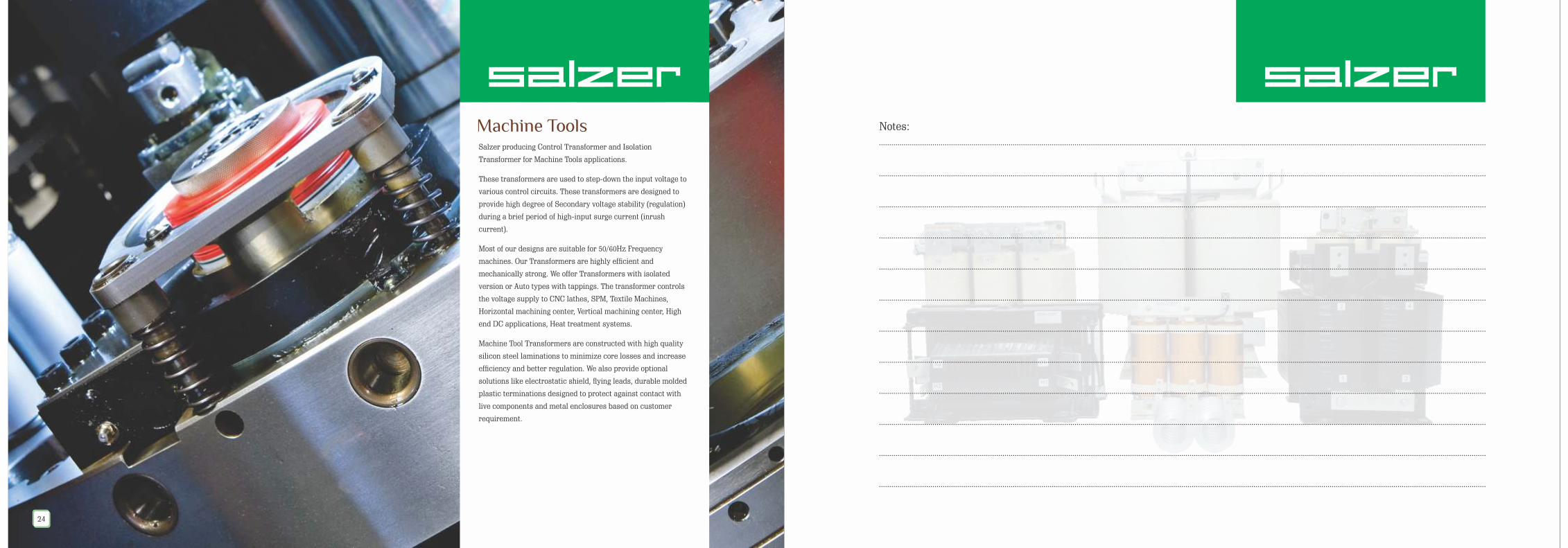
Salzer producing Control Transformer and Isolation
Transformer for Machine Tools applications.
These transformers are used to step-down the input voltage to
various control circuits. These transformers are designed to
provide high degree of Secondary voltage stability (regulation)
during a brief period of high-input surge current (inrush
current).
Most of our designs are suitable for 50/60Hz Frequency
machines. Our Transformers are highly efcient and
mechanically strong. We offer Transformers with isolated
version or Auto types with tappings. The transformer controls
the voltage supply to CNC lathes, SPM, Textile Machines,
Horizontal machining center, Vertical machining center, High
end DC applications, Heat treatment systems.
Machine Tool Transformers are constructed with high quality
silicon steel laminations to minimize core losses and increase
efciency and better regulation. We also provide optional
solutions like electrostatic shield, ying leads, durable molded
plastic terminations designed to protect against contact with
live components and metal enclosures based on customer
requirement.
Machine Tools
24
.......................................................................................................................................................................................................................................................................................................
Notes:
.......................................................................................................................................................................................................................................................................................................
.......................................................................................................................................................................................................................................................................................................
.......................................................................................................................................................................................................................................................................................................
.......................................................................................................................................................................................................................................................................................................
.......................................................................................................................................................................................................................................................................................................
.......................................................................................................................................................................................................................................................................................................
.......................................................................................................................................................................................................................................................................................................
.......................................................................................................................................................................................................................................................................................................
.......................................................................................................................................................................................................................................................................................................
.......................................................................................................................................................................................................................................................................................................
.......................................................................................................................................................................................................................................................................................................

Other products:
8�Rotary Switches / Load Break Switches
8�Photo Voltaic Isolators
8�Cable Ducts & Special Proles
8�Terminal Connectors
Relays & Contactors8�
8�Motor Protection Circuit Breaker (MPCB)
Toroidal Transformers & CT’s8�
Limit & Foot Swiches8�
MCB’s & Distribution Boards8�
Automatic Changeover with Current limiter8�
Wires & Cables / Wire Harness8�
Sensors8�
Enameled Wires & Flexible Busbar8�
n n n n�India's leader in Rotary Switches & Wiring Ducts �International product approvals �Worldwide market presence �Five units with International affiliations
Salzer Electronics LimitedRegistered & Corporate Office: Samichettipalayam, Coimbatore - 641 047 India
Salzer Unit II : Chinnamaddampalaym, Coimbatore - 641 019 Tel: +91 4254 302000 Fax: +91 4254 272012 E-mail: [email protected] | | |
®
www. salzergroup.com