Embed Size (px)
Citation preview
Magnetic amplifiers & Saturable reactors Ricciarelli Fabrizio 01/01/2016
Magnetic amplifiers and saturable reactors
Pag. 1 / 15
Summary SECTION I.......................................................................................................................................................... 2
What are the saturable reactors .................................................................................................................. 2
SECTION II ......................................................................................................................................................... 3
Types of reactors .......................................................................................................................................... 3
Saturable reactors .................................................................................................................................... 4
Linear reactors .......................................................................................................................................... 4
Control modules ....................................................................................................................................... 4
SECTION III ........................................................................................................................................................ 5
History .......................................................................................................................................................... 5
How they are made and how they operate .................................................................................................. 6
Feedback ...................................................................................................................................................... 8
Reliability ...................................................................................................................................................... 8
SECTION IV ..................................................................................................................................................... 10
A practical approach ................................................................................................................................... 10
Magnetic amplifier with reactance coils in series ....................................................................................... 13
Magnetic amplifier with reactance coils in parallel .................................................................................... 13
Control of a l20 volt lamp using an output step up transformer ................................................................ 14
Adding a couple of diodes causes incredible increase in gain .................................................................... 14
Magnetic amplifiers and saturable reactors
Pag. 2 / 15
SECTION I
What are the saturable reactors Saturable reactors are not common electromagnetic components; here is a brief overview of why saturable reactors are occasionally referred to as magnetic amplifiers:
1. Saturable reactors are considered magnetic amplifiers because they can use a relatively small amount of DC volt-amps to control the transfer of a significant amount of AC volt-amps: the DC input is referred to as the control.
2. The relationship between the DC control volt-amps and AC volt-amps is called the amplification factor.
3. The amplification ratio is often expressed as a ratio: output volt-amps divided by the control volt-amps.
4. Saturable reactors are commonly used to transfer a system voltage to a load through a series impedance division circuit.
5. The saturable reactor is wired in series with the load impedance and the combination is connected across the system voltage.
6. The magnitude of the voltage reaching the load is determined by the ratio of the load impedance to the total series impedance (load + reactor).
7. By reducing the impedance of the saturable reactor, the load impedance becomes a higher percentage of the total impedance and thus more of the input voltage is dropped (transferred) across the load.
8. Since both the saturable reactor and the load may consist of resistive and reactive components, each device has an impedance that is the vector sum of its resistance and reactance.
9. The method used to change the impedance of the saturable reactor is to change its inductance, thus its inductive reactance and therefore its impedance.
10. One technique designers can use to produce the appropriate level of inductance is to optimize the permeability of the magnetic core.
11. With no DC control current present, the permeability of the core is at its highest value and the inductance is therefore at its highest value.
12. An series analysis will reveal the quantity how much of the system voltage reaches the load under this condition.
13. With the application of a DC control current, significant enough to saturate the inductance, the impedance of the reactor is reduced to nearly the value of only its resistance; under this excitation, the greatest value of the system voltage is dropped (transferred) to the load.
14. For the full system voltage to reach the load, the load impedance must be significantly higher than the resistive component of the reactor.
15. A typical amplification factor for a 10 KVA saturable reactor, requiring 150 Watts of DC control for full output, is 10,000 / 150 = 67.
(source: http://osbornetransformer.com/saturable-reactors-are-magnetic-amplifiers/)
Magnetic amplifiers and saturable reactors
Pag. 3 / 15
SECTION II
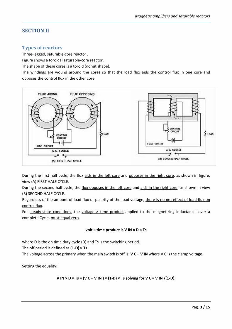
Types of reactors Three-legged, saturable-core reactor . Figure shows a toroidal saturable-core reactor. The shape of these cores is a toroid (donut shape). The windings are wound around the cores so that the load flux aids the control flux in one core and opposes the control flux in the other core.
During the first half cycle, the flux aids in the left core and opposes in the right core, as shown in figure, view (A) FIRST HALF CYCLE. During the second half cycle, the flux opposes in the left core and aids in the right core, as shown in view (B) SECOND HALF CYCLE. Regardless of the amount of load flux or polarity of the load voltage, there is no net effect of load flux on control flux. For steady-state conditions, the voltage × time product applied to the magnetizing inductance, over a complete Cycle, must equal zero.
volt × time product is V IN × D × Ts where D is the on time duty cycle (D) and Ts is the switching period. The off period is defined as (1-D) × Ts. The voltage across the primary when the main switch is off is: V C – V IN where V C is the clamp voltage. Setting the equality:
V IN × D × Ts = (V C – V IN ) × (1-D) × Ts solving for V C = V IN /(1-D).
Magnetic amplifiers and saturable reactors
Pag. 4 / 15
Saturable reactors The Saturable Reactor consists of two core and coil assemblies each with two AC coils and two DC coils. Two assemblies are required to avoid inducing AC voltage into the DC circuitry. The DC winding provides the “variable-saturation” of the cores and so forces the AC reactance of the assembly to change. It is made of M6 Grain Oriented Steel laminations/ or square B-H lamination as desired by the application and Nomex insulated copper windings. Together with the linear reactor, the saturable reactor provides part of a variable voltage divider, which effectively slides the output voltage up and down, effectively providing voltage regulation.
Linear reactors The Linear Reactor is of a similar design to a single-phase transformer except that it only has one winding, half on each limb. It is made of M6 Grain Oriented Steel laminations and Nomex insulated copper windings. The core has a number of carefully dimensioned gaps equally shared between the two core legs. The gaps are filled with Polyester-glass or Nomex insulation or both. The reactance is maintained at a constant value over a large operating range. The ratio between the linear reactance and the reactance of the saturable reactor can thus be accurately determined and used to control the voltage divider.
Control modules The plug-in controller module provides DC Chopper, the contol winding current may be controlled. There is one controller Per phase. The input voltage to the controller is a sample of the Voltage Regulator output voltage. It is sensed by a true - rms converter and compared with a stable reference voltage. The difference signal drives the Chopper driver, which provides phase fixed gate drive output. The adjustment of this controller is limited to the output voltage adjustment potentiometer. These will work exactly like two thyristors Back to Back, without the fear of loss of sync or current shoot-ups. These will do lovely phase control for whatever application assuming non-capacitive loads. These are called amplifiers because, small control current can control large load current. (source: http://www.transformerssigma.com/magnetic-amplifiers-and-reactors.html)
Magnetic amplifiers and saturable reactors
Pag. 5 / 15
SECTION III
History Magnetic amplifier have been around since the beginning of the 20th century and have been used extensively in heavy industrial and military equipment controls. Their appearance is very similar to a typical electrical transformer, but the function is completely different. Basically, the magnetic amplifier is a current-controlled impedance changer. The current applied to the primary winding controls the degree of saturation in the secondary, which in turn causes the impedance of the secondary to vary. That action makes it functions like an electrically controlled rheostat. The atomic submarine Triton glides swiftly and silently through the deep. As its power plant purrs steadily, scores of electronic watchdogs probe every part of the sub's powerful reactor. Suddenly the pressure in a reaction chamber begins to rise over the allowable amount. One of the electronic guardians instantly notes the rise and applies a corrective signal - before a human operator could know that anything had begun to go wrong. The electronic watchdogs that keep the Triton's powerful nuclear plant operating without a hitch are magnetic amplifiers - almost a hundred of them are used for this critical job. Yet these same magnetic amplifiers - the heart of the control system of one of the world's most up-to-the-minute fighting machines are straight out of the horse-and-buggy era. Scores of magnetic amplifiers in the world-circling Triton control its atomic reactor. Above, finishing touches are put on the General Electric "magnetic" that monitors the reactor's temperature. Magnetic amplifiers came into being when the century was just one year old. It would be six years - in 1907 - before a youngster named Lee de Forest would make news with his audion, the world's first vacuum-tube amplifier. And the transistor was still 47 years in the future. For a while, it looked as though the magnetic amplifier would hold its own against that upstart, the audion. In 1916, E. F. W. Alexanderson, the electronic pioneer, employed magnetic amplifiers to modulate his early transmitters and many World War I transmitting stations used his circuits. By the early 20's, however, the flashy vacuum tube had taken over, and the "magnetic" was almost forgotten in this country. It was not forgotten in Germany, however, as we found out when World War II started. In the years between the wars, the Germans had brought the magnetic amplifier to a high state of development. War-time found them using magnetics for reliable, accurate, and trouble-free control of everything from gun turrets to automatic pilot systems, and they even used them in the V2 rockets. Awakened to the possibilities inherent in this design, Allied scientists began to push the development of magnetic amplifiers. Before much progress had been made, though, the war was over. But the spark had been kindled, and a few years later Vickers Inc. (now a division of Sperry Rand) came out with the first commercially produced magnetics. By that time, interest had been aroused all over the world. In the following decade, hundreds of other firms, including all the big names in electrical and electronic equipment, have added magnetics to their product lines.
Magnetic amplifiers and saturable reactors
Pag. 6 / 15
And almost no branch of industry now operates without them. A modern-day magnetic amplifier is, essentially, nothing more than an iron core with two or more coils of wire wound around it.
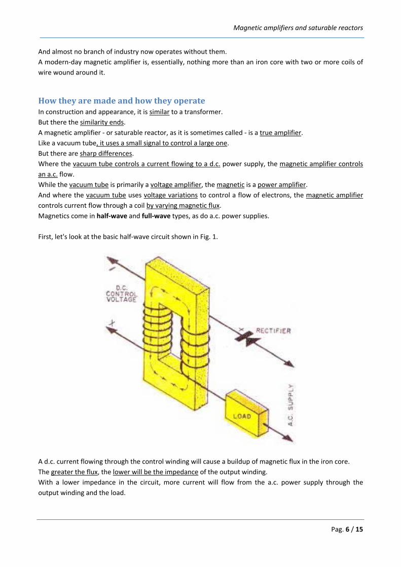
How they are made and how they operate In construction and appearance, it is similar to a transformer. But there the similarity ends. A magnetic amplifier - or saturable reactor, as it is sometimes called - is a true amplifier. Like a vacuum tube, it uses a small signal to control a large one. But there are sharp differences. Where the vacuum tube controls a current flowing to a d.c. power supply, the magnetic amplifier controls an a.c. flow. While the vacuum tube is primarily a voltage amplifier, the magnetic is a power amplifier. And where the vacuum tube uses voltage variations to control a flow of electrons, the magnetic amplifier controls current flow through a coil by varying magnetic flux. Magnetics come in half-wave and full-wave types, as do a.c. power supplies. First, let's look at the basic half-wave circuit shown in Fig. 1.
A d.c. current flowing through the control winding will cause a buildup of magnetic flux in the iron core. The greater the flux, the lower will be the impedance of the output winding. With a lower impedance in the circuit, more current will flow from the a.c. power supply through the output winding and the load.
Magnetic amplifiers and saturable reactors
Pag. 7 / 15
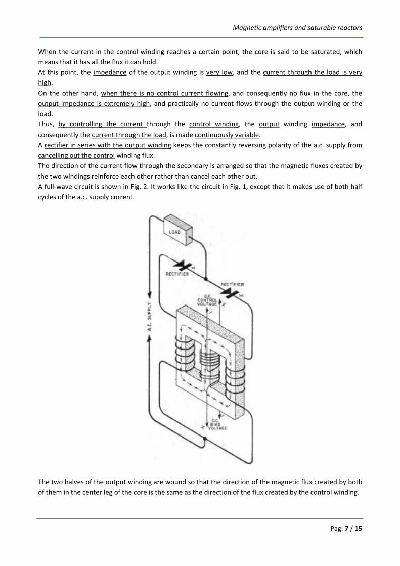
When the current in the control winding reaches a certain point, the core is said to be saturated, which means that it has all the flux it can hold. At this point, the impedance of the output winding is very low, and the current through the load is very high. On the other hand, when there is no control current flowing, and consequently no flux in the core, the output impedance is extremely high, and practically no current flows through the output winding or the load. Thus, by controlling the current through the control winding, the output winding impedance, and consequently the current through the load, is made continuously variable. A rectifier in series with the output winding keeps the constantly reversing polarity of the a.c. supply from cancelling out the control winding flux. The direction of the current flow through the secondary is arranged so that the magnetic fluxes created by the two windings reinforce each other rather than cancel each other out. A full-wave circuit is shown in Fig. 2. It works like the circuit in Fig. 1, except that it makes use of both half cycles of the a.c. supply current.
The two halves of the output winding are wound so that the direction of the magnetic flux created by both of them in the center leg of the core is the same as the direction of the flux created by the control winding.
Magnetic amplifiers and saturable reactors
Pag. 8 / 15
The bias winding can be used to control the general range of the amplifier's operation, just as the bias on a vacuum tube causes the tube to operate on a certain part of its characteristic curve. In a magnetic amplifier, when a small bias current flows, a certain amount of flux is continuously present in the core, even with no control voltage supplied. Thus, the impedance of the output winding will never reach its maximum value, nor will the current through the load reach its minimum.
Feedback Many magnetic amplifiers have an additional control winding which is used for feedback. This winding taps a certain amount of the output circuit's current and applies it back as a control current. As with a vacuum tube, the feedback can be either negative or positive. In general, negative feedback improves the linearity of the amplifier while positive feedback increases its gain. Single-stage magnetics can be built with gains of about 200,000, far beyond the capabilities of the vacuum tube. With a gain on this order, a few milliwatts of power in the control winding - an amount that could be supplied by one or two flashlight cells - may control a load of 25,000 watts in the output circuit.
Reliability Magnetics are extremely rugged. They can be - and frequently are - completely potted and sealed in airtight containers. They thrive on extremes of heat, dust, moisture, vibration, and other adverse conditions that would put vacuum tubes and transistors out of operation. Their efficiency is high, as with transformers and other magnetic devices. In addition, no filament current is required. So little heat is generated by magnetics that they can be packed into extremely small containers which need practically no ventilation or cooling. Because magnetics can handle large amounts of current easily, they are a natural choice for electric furnace control. A Reynolds Aluminum Company furnace in Corpus Christi, Texas, uses such a control system. Precise furnace control by magnetics also helps to "grow" transistors in the latest types of transistor-manufacturing processes. Magnetics have recently begun to invade the field of entertainment, too. NBC's two big color television studies - one in Burbank, California, the other in Brooklyn, N. Y. - have magnetic amplifier lighting-control systems. With this setup, the lighting man has fingertip control over each of the hundreds of lights throughout the studio. He can control them individually or in banks, as he desires, working from a small keyboard that looks something like an organ console. Unlike older types of theatre lighting devices - autotransformers and rheostats - magnetics present no fire hazard. Since magnetic amplifiers have no moving parts and no delicate components, they last for years with virtually no maintenance.
Magnetic amplifiers and saturable reactors
Pag. 9 / 15
For this reason, they are used in such critical applications as the control of the atomic pile in nuclear subs and in missile-guidance systems, where reliability under adverse conditions of vibration, heat, and acceleration is vital. Reliability is also the reason magnetics were chosen to monitor and control the critical voltages and currents of the transatlantic cable. If a voltage begins to change, a magnetic compensates for the change, and, at the same time, sounds an alarm so an operator can check to find the reason for the change. If the current drawn by the underwater repeater amplifier tubes begins to rise, once again the alarm is given, and corrective action is taken automatically. By insuring that the current does not rise to dangerous levels, the magnetics prolong the lives of the submerged tubes. This is important because lifting the cable to replace a damaged tube costs thousands of dollars. Basic magnetic amplifier circuits can be modified to give special effects. For example, a magnetic to which excessive positive feedback has been applied becomes "bistable". This means that it is stable in only two states of operation: maximum output or minimum output. There is no in-between. The amplifier is adjusted so that the core is normally in a non-saturated state. But even the tiniest input signal - perhaps only a few microamperes - will throw it into complete saturation. Thus it becomes the equivalent of an extremely sensitive switch, or relay. But a magnetic amplifier is a switch without moving parts or contacts, and it is virtually indestructible. The bistable magnetic is beginning to find widespread use as a replacement for relays where long, reliable service is of great importance. Several automotive companies - the Ford Motor Co., for example - are now using magnetics to control the flow of parts in the engine assembly line. First, proximity switches containing magnetic amplifiers sense the presence or absence of necessary parts on an automated line. Other magnetics, cued by the proximity switch, supply the parts as needed. Since there are no moving components and no contacts, these magnetics show no signs of wear after millions upon millions of operations - long after normal relay contacts would have worn out. Another series of magnetics controls the speed of the engine assembly conveyor, to determine the proper production rate. The uses for magnetic amplifiers are almost limitless. They serve as memory units in computers and as speed regulators in steel, paper, and textile mills; they control gun turrets and radar antennas on navy ships; they regulate the voltage output of huge turbine generators; they control automatic elevators, mine hoists, power shovels, cranes, and printing presses. In short, wherever the considerations of precise, reliable, trouble-free control are important - from jet aircraft to atomic submarines - you'll find magnetic amplifiers working silently and efficiently. (source: http://www.rfcafe.com/references/popular-electronics/magnetic-amplifiers-jul-1960-popular-electronics.htm)
Magnetic amplifiers and saturable reactors
Pag. 10 / 15
SECTION IV
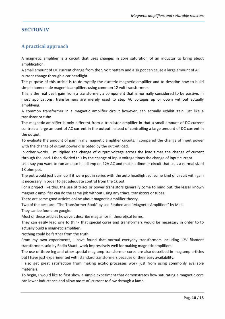
A practical approach A magnetic amplifier is a circuit that uses changes in core saturation of an inductor to bring about amplification. A small amount of DC current change from the 9 volt battery and a 1k pot can cause a large amount of AC current change through a car headlight. The purpose of this article is to de-mystify the esoteric magnetic amplifier and to describe how to build simple homemade magnetic amplifiers using common 12 volt transformers. This is the real deal; gain from a transformer, a component that is normally considered to be passive. In most applications, transformers are merely used to step AC voltages up or down without actually amplifying. A common transformer in a magnetic amplifier circuit however, can actually exhibit gain just like a transistor or tube. The magnetic amplifier is only different from a transistor amplifier in that a small amount of DC current controls a large amount of AC current in the output instead of controlling a large amount of DC current in the output. To evaluate the amount of gain in my magnetic amplifier circuits, I compared the change of input power with the change of output power dissipated by the output load. In other words, I multiplied the change of output voltage across the load times the change of current through the load. I then divided this by the change of input voltage times the change of input current. Let's say you want to run an auto headlamp on 12V AC and make a dimmer circuit that uses a normal sized 1K ohm pot. The pot would just burn up if it were put in series with the auto headlight so, some kind of circuit with gain is necessary in order to get adequate control from the 1k pot. For a project like this, the use of triacs or power transistors generally come to mind but, the lesser known magnetic amplifier can do the same job without using any triacs, transistors or tubes. There are some good articles online about magnetic amplifier theory. Two of the best are: “The Transformer Book” by Lee Reuben and “Magnetic Amplifiers” by Mali. They can be found on google. Most of these articles however, describe mag amps in theoretical terms. They can easily lead one to think that special cores and transformers would be necessary in order to to actually build a magnetic amplifier. Nothing could be farther from the truth. From my own experiments, I have found that normal everyday transformers including 12V filament transformers sold by Radio Shack, work impressively well for making magnetic amplifiers. The use of three leg and other special mag amp transformer cores are also described in mag amp articles but I have just experimented with standard transformers because of their easy availability. I also get great satisfaction from making exotic processes work just from using commonly available materials. To begin, I would like to first show a simple experiment that demonstrates how saturating a magnetic core can lower inductance and allow more AC current to flow through a lamp.
Magnetic amplifiers and saturable reactors
Pag. 11 / 15
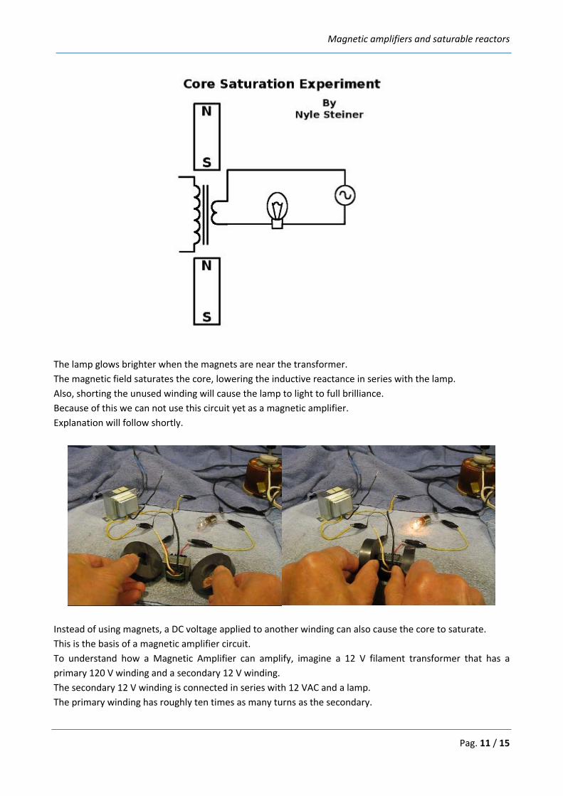
The lamp glows brighter when the magnets are near the transformer. The magnetic field saturates the core, lowering the inductive reactance in series with the lamp. Also, shorting the unused winding will cause the lamp to light to full brilliance. Because of this we can not use this circuit yet as a magnetic amplifier. Explanation will follow shortly.
Instead of using magnets, a DC voltage applied to another winding can also cause the core to saturate. This is the basis of a magnetic amplifier circuit. To understand how a Magnetic Amplifier can amplify, imagine a 12 V filament transformer that has a primary 120 V winding and a secondary 12 V winding. The secondary 12 V winding is connected in series with 12 VAC and a lamp. The primary winding has roughly ten times as many turns as the secondary.
Magnetic amplifiers and saturable reactors
Pag. 12 / 15
By running a small DC control current through the 120 V primary winding, amplification is possible because this small current can generate enough ampere turns to saturate the core. This lowers the inductive reactance of the 12V secondary, allowing more AC current to flow through the lamp making it brighter. A small change in DC current applied to the 120 V primary winding can cause a much larger change in AC current flowing through the 12 V secondary winding. This can be stated another way. A small change in power dissipated across the 120V primary can cause a much larger change in power dissipated across a load connected to the 12 V secondary. This circuit configuration however, presents some problems that need to be addressed. When using a single transformer, high voltage AC will appear, through transformer action, across the 120 V control winding. This high voltage can burn up a potentiometer or whatever is connected to this 120 V winding. We don't want to have this high voltage AC coming out of the magnetic amplifier input. There is also the problem that the lamp will light to full brilliance if the 120 V control winding is simply shorted. With no input applied to the amplifier, it should not make any difference whether the input is open or shorted. A solution to this is to use two transformers. The output AC current can be run through the 12 V windings of both transformers either in series or parallel. The 120 V input windings can be connected in series so that the AC voltages induced in them from transformer action, are out of phase and cancel. This allows small DC control voltages to be applied to the two 120 V windings without interaction with high voltage AC. Since each transformer core can saturate, independently of the other, the DC control windings have full core saturation effect even though they are connected out of phase. It is easy to tell when the two input control windings are phased properly by shorting the input. If the phase is wrong, the lamp will light to full brilliance. If the phase is correct, the lamp condition will show little or no change. With this type of Magnetic Amplifier circuit, the lamp will normally be dim or off when zero control voltage is applied. DC control voltages of plus or minus polarity, when applied to the input, will cause the lamp to get brighter.
Magnetic amplifiers and saturable reactors
Pag. 13 / 15
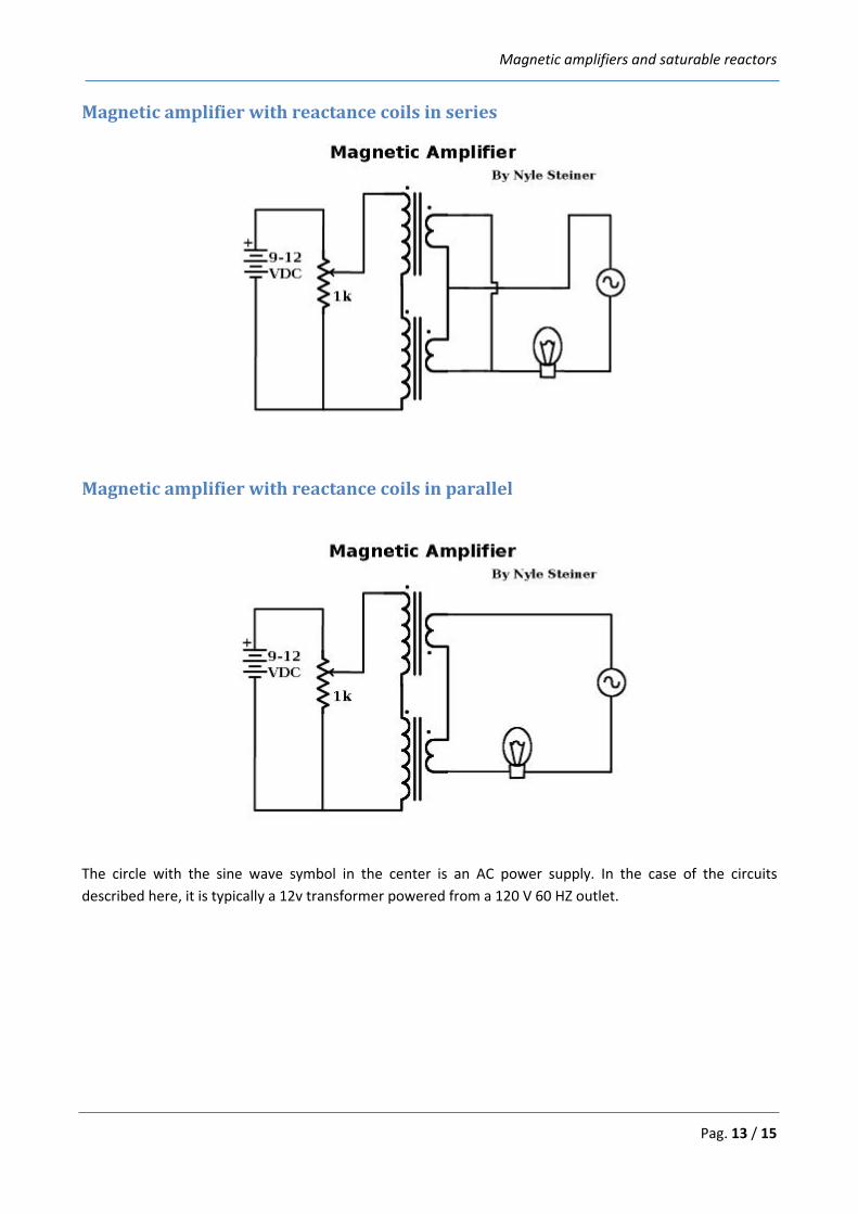
Magnetic amplifier with reactance coils in series
Magnetic amplifier with reactance coils in parallel
The circle with the sine wave symbol in the center is an AC power supply. In the case of the circuits described here, it is typically a 12v transformer powered from a 120 V 60 HZ outlet.
Magnetic amplifiers and saturable reactors
Pag. 14 / 15
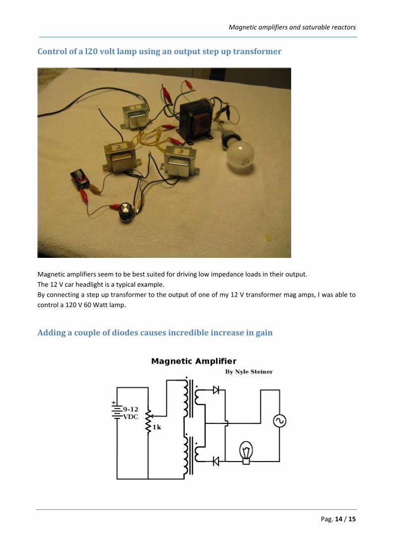
Control of a l20 volt lamp using an output step up transformer
Magnetic amplifiers seem to be best suited for driving low impedance loads in their output. The 12 V car headlight is a typical example. By connecting a step up transformer to the output of one of my 12 V transformer mag amps, I was able to control a 120 V 60 Watt lamp.
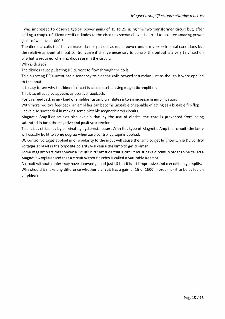
Adding a couple of diodes causes incredible increase in gain
Magnetic amplifiers and saturable reactors
Pag. 15 / 15
I was impressed to observe typical power gains of 15 to 25 using the two transformer circuit but, after adding a couple of silicon rectifier diodes to the circuit as shown above, I started to observe amazing power gains of well over 1000!! The diode circuits that I have made do not put out as much power under my experimental conditions but the relative amount of input control current change necessary to control the output is a very tiny fraction of what is required when no diodes are in the circuit. Why is this so? The diodes cause pulsating DC current to flow through the coils. This pulsating DC current has a tendency to bias the coils toward saturation just as though it were applied to the input. It is easy to see why this kind of circuit is called a self biasing magnetic amplifier. This bias effect also appears as positive feedback. Positive feedback in any kind of amplifier usually translates into an increase in amplification. With more positive feedback, an amplifier can become unstable or capable of acting as a bistable flip flop. I have also succeeded in making some bistable magnetic amp circuits. Magnetic Amplifier articles also explain that by the use of diodes, the core is prevented from being saturated in both the negative and positive direction. This raises efficiency by eliminating hysteresis losses. With this type of Magnetic Amplifier circuit, the lamp will usually be lit to some degree when zero control voltage is applied. DC control voltages applied in one polarity to the input will cause the lamp to get brighter while DC control voltages applied in the opposite polarity will cause the lamp to get dimmer. Some mag amp articles convey a "Stuff Shirt" attitude that a circuit must have diodes in order to be called a Magnetic Amplifier and that a circuit without diodes is called a Saturable Reactor. A circuit without diodes may have a power gain of just 15 but it is still impressive and can certainly amplify. Why should it make any difference whether a circuit has a gain of 15 or 1500 in order for it to be called an amplifier?