Embed Size (px)
Citation preview
Edited by: S. Ekinović, I. Buj-Corral, S. Yalcin
Journal of Trends in the Development of Machinery
and Associated Technology
Vol. 21, No. 1, 2018, ISSN 2303-4009 (online), p.p. 117-120
FINAL DESIGN AND CONSTRUCTION OF A TEST BENCH FOR
MEASURING FRICTION FORCES IN COMBUSTION ENGINES
Irene Buj-Corral, Enrique Zayas-Figueras, Jesús Álvarez-Flórez, Ernesto Gutiérrez-
González, Pol Ribas-Villa
Universitat Politècnica de Catalunya (UPC)
School of Engineering of Barcelona (ETSEIB)
Av. Diagonal, 647. 08028. Barcelona
Spain
ABSTRACT In this paper the final design and the construction of a test bench for measuring friction forces in a
piston-cylinder system is presented. Requirements of the bench and conceptual design were exposed
in a previous paper. The bench consists of five modules: power module, engine module, block module,
lubrication module and data acquisition module. Power module contains electric motor and mechanical transmission. Engine module has a crank, a connecting rod and a piston. Block module
comprises block and cylinder. Lubrication module will be included in future works. It will consist of a
piezoelectric device and a high frequency feeding system. Finally, data acquisition module consists of a phonic wheel, an inductive sensor and strain gages. The bench allows interchange of cylinders with
different surface finish, obtained by means of honing processes.
Keywords: final design, test bench, friction forces, cylinder-piston system
1. INTRODUCTION
In a previous paper, conceptual design of a test bench for measuring friction forces in a piston-
cylinder system was proposed. There, the design requirements of the bench were established [1]. The proposed design consists of five modules: power module, engine module, block module, lubrication
module (not included) and data acquisition module. In the present paper, the detail design of each
module, as well as the virtual design and the construction of a prototype of the bench, is presented. From the study of the state of the art, it was found that test benches can be classified into two groups.
First one is dedicated to testing of internal combustion engines (performance of the engine or friction
–global friction, piston-cylinder friction and friction with cylinder exchange). Second one corresponds to tribological benches (with rotation or translation movement). The bench proposed in the present
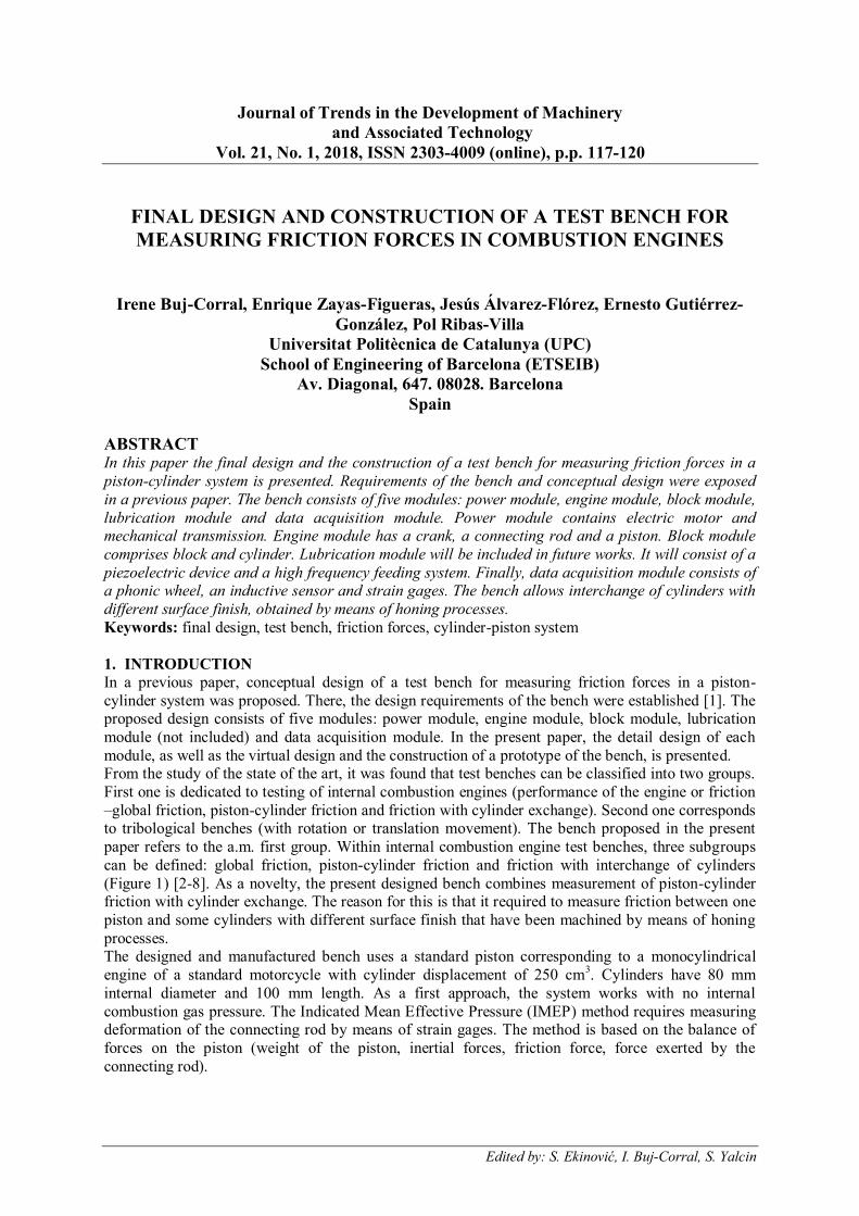
paper refers to the a.m. first group. Within internal combustion engine test benches, three subgroups
can be defined: global friction, piston-cylinder friction and friction with interchange of cylinders
(Figure 1) [2-8]. As a novelty, the present designed bench combines measurement of piston-cylinder friction with cylinder exchange. The reason for this is that it required to measure friction between one
piston and some cylinders with different surface finish that have been machined by means of honing
processes. The designed and manufactured bench uses a standard piston corresponding to a monocylindrical
engine of a standard motorcycle with cylinder displacement of 250 cm3. Cylinders have 80 mm
internal diameter and 100 mm length. As a first approach, the system works with no internal
combustion gas pressure. The Indicated Mean Effective Pressure (IMEP) method requires measuring deformation of the connecting rod by means of strain gages. The method is based on the balance of
forces on the piston (weight of the piston, inertial forces, friction force, force exerted by the
connecting rod).
118
Figure 1. Classification of test benches for friction measurement.
In the next section, the detail design of the different modules of the test bench is exposed. The paper
presents, in a summarized way, some aspects of the selection process of the different commercial
components (electrical motor selection, pulley transmission, etc.) and of the calculation of non-commercial components, for example the inertial wheel.
2. DETAIL DESIGN OF THE BENCH
Taking into account the conceptual design of the bench [1], five different modules were designed: power module, engine module, block module, lubrication module and instrumentation and acquisition
module. Lubrication module will be included in further works.
In order to select the components of the bench modules among different design options, selection matrices were employed [9]. In the next subsections, the different modules will be explained in a
summarized way.
2.1. Power module The power module comprises an electric motor with speed control, transmission pulleys and a V-belt.
In this case, there is not compression phase in the combustion engine, so, in order to determine the
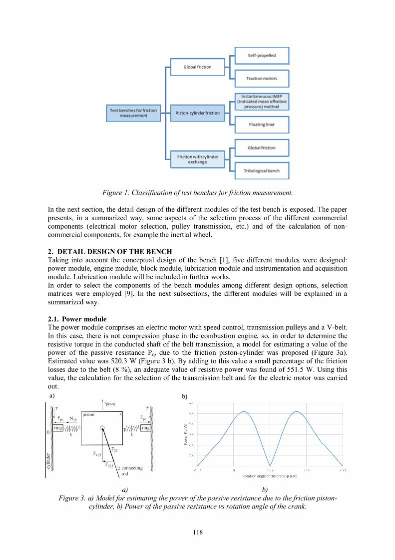
resistive torque in the conducted shaft of the belt transmission, a model for estimating a value of the power of the passive resistance Prp due to the friction piston-cylinder was proposed (Figure 3a).
Estimated value was 520.3 W (Figure 3 b). By adding to this value a small percentage of the friction
losses due to the belt (8 %), an adequate value of resistive power was found of 551.5 W. Using this value, the calculation for the selection of the transmission belt and for the electric motor was carried
out.
a) b)
Figure 3. a) Model for estimating the power of the passive resistance due to the friction piston-cylinder, b) Power of the passive resistance vs rotation angle of the crank.
a) b)

119
From the above model, and assuming a steel-steel friction coefficient 0 57steel steel .-m = [10] the
following expression was obtained (Equation 1).
( )30steel steel pcT N F-= m × + (1)
Where T is the estimated tangential force (N), N30 is the normal force between piston and cylinder (N)
determinate by using the PAM software, and Fpc is the force exerted by the rings (N) measured with a
dynamometer.
From the tangential force T, and using the speed of the piston vp also was obtained by means of the
PAM software, the power of the passive resistances Pfp is calculated (Equation 2).
fp pP T v= × (2)
From the values above, and using the corresponding procedure of belt and motor selection, an SPZ
profile V-belt and an AC motor was selected.
2.2. Engine module, block module and data acquisition module
In order to determine the geometry and inertial characteristics of the elements of the engine module, a kinematic and dynamic analysis of the slider-crank mechanism was made using the PAM software
[11]. A dynamic forces analysis, very important in a single piston engines, was performed,
determining the value of the forces applied by the piston N30 and the crank F10 to the frame. In order to
reduce the magnitude of such forces, making a balance of such mechanism and accomplishing with an
adequate range of a coefficient of fluctuation of speed ( 0 0125 0 006. .d= - ). Thus, the dimension and
the mass moment of inertia, as well as the location of the gravity center of an inertial flywheel was determined. Figures 4 a) and 4 b) depict the forces in the mechanism and the graphic of the force F10
and its components during a rotation cycle of the crank. The connecting rod has a weak section in
order to permit measuring its deformation by means of strain gages.
Figure 4. a) Forces scheme (including the flywheel), b) Graphic of the fluctuation of the force F10
once the mechanism has been balanced
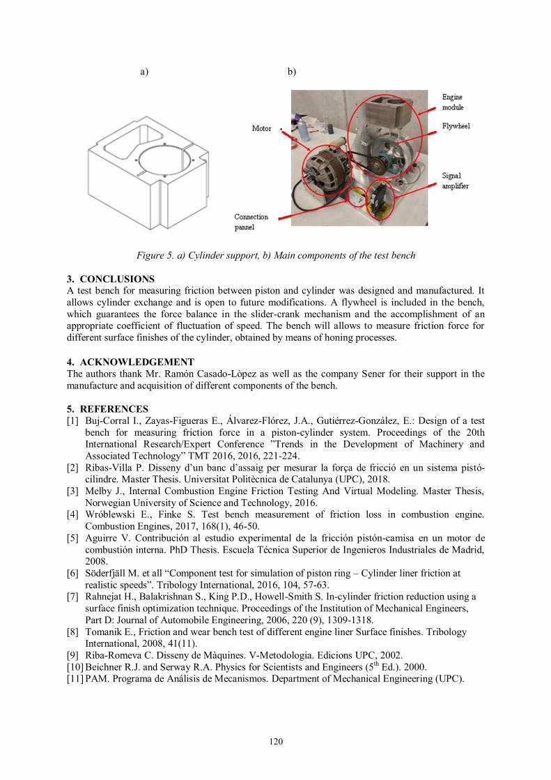
The block module was designed and manufactured with a cylinder support that has a groove acting as a clamp, in a way that it allows fixing the cylinder and also the cylinder exchange (Figure 5 a).
The data acquisition module consists of a phonic wheel with an inductive sensor, strain gages and a
signal amplifier. In Figure 5 b) a picture of the assembled test bench is shown. The main parts of the bench are
indicated.
-400
-300
-200
-100
0
100
200
300
400
-1,57 0 1,57 3,14 4,71
Forc
e [N
]
Rotation angle φ [rad]
Fh01 Fv01 F01
b) a)
120
a) b)
Figure 5. a) Cylinder support, b) Main components of the test bench
3. CONCLUSIONS A test bench for measuring friction between piston and cylinder was designed and manufactured. It
allows cylinder exchange and is open to future modifications. A flywheel is included in the bench,
which guarantees the force balance in the slider-crank mechanism and the accomplishment of an appropriate coefficient of fluctuation of speed. The bench will allows to measure friction force for
different surface finishes of the cylinder, obtained by means of honing processes.
4. ACKNOWLEDGEMENT
The authors thank Mr. Ramón Casado-Lòpez as well as the company Sener for their support in the
manufacture and acquisition of different components of the bench.
5. REFERENCES
[1] Buj-Corral I., Zayas-Figueras E., Álvarez-Flórez, J.A., Gutiérrez-González, E.: Design of a test
bench for measuring friction force in a piston-cylinder system. Proceedings of the 20th International Research/Expert Conference ”Trends in the Development of Machinery and
Associated Technology” TMT 2016, 2016, 221-224.
[2] Ribas-Villa P. Disseny d’un banc d’assaig per mesurar la força de fricció en un sistema pistó-cilindre. Master Thesis. Universitat Politècnica de Catalunya (UPC), 2018.
[3] Melby J., Internal Combustion Engine Friction Testing And Virtual Modeling. Master Thesis,
Norwegian University of Science and Technology, 2016. [4] Wróblewski E., Finke S. Test bench measurement of friction loss in combustion engine.
Combustion Engines, 2017, 168(1), 46-50.
[5] Aguirre V. Contribución al estudio experimental de la fricción pistón-camisa en un motor de
combustión interna. PhD Thesis. Escuela Técnica Superior de Ingenieros Industriales de Madrid, 2008.
[6] Söderfjäll M. et all “Component test for simulation of piston ring – Cylinder liner friction at
realistic speeds”. Tribology International, 2016, 104, 57-63. [7] Rahnejat H., Balakrishnan S., King P.D., Howell-Smith S. In-cylinder friction reduction using a
surface finish optimization technique. Proceedings of the Institution of Mechanical Engineers,
Part D: Journal of Automobile Engineering, 2006, 220 (9), 1309-1318.
[8] Tomanik E., Friction and wear bench test of different engine liner Surface finishes. Tribology International, 2008, 41(11).
[9] Riba-Romeva C. Disseny de Màquines. V-Metodologia. Edicions UPC, 2002.
[10] Beichner R.J. and Serway R.A. Physics for Scientists and Engineers (5th Ed.). 2000.
[11] PAM. Programa de Análisis de Mecanismos. Department of Mechanical Engineering (UPC).