Embed Size (px)
Citation preview
1
Lecture 1 of 2 – For graduate level students of physics or electrical engineering
www.kyatera.fapesp.br
Fundamentals of Fiber-Optic Communication Systems
Fundamentals of Fiber-Optic Communication Systems
Prof. Hugo L. FragnitoOptics and Photonics Research Center at Unicamp
Tel. (xx55-19) [email protected]
UNICAMP-IFGWInstituto de Física Gleb Wataghin, Campinas, 13083-970, SP, Brazil
555 H. Fragnito H. Fragnito H. Fragnito CePOFCePOFCePOF ––– UNICAMPUNICAMPUNICAMP
Elements of a Communication SystemElements of a Communication System
ReceiverTransmitter
InputTx Transmission Line Rx
Output
Optical fiberLaser +
modulatorPhotodiode +Filter + clock recovery + ...
666 H. Fragnito H. Fragnito H. Fragnito CePOFCePOFCePOF ––– UNICAMPUNICAMPUNICAMP
MultiplexingMultiplexing
Multiplexer DemultiplexerChannel 1
Channel N
Voice, video, or data channels
Channel 1
Channel N
MUX DEMUX
Tx Rx
Multiplexing can be in time domain (TDM), frequency domain (FDM), Polarization (PDM), Wavelength (WDM), ...
TDM = Time Division Multiplexing, FDM = Frequency Division Multiplexing,
777 H. Fragnito H. Fragnito H. Fragnito CePOFCePOFCePOF ––– UNICAMPUNICAMPUNICAMP
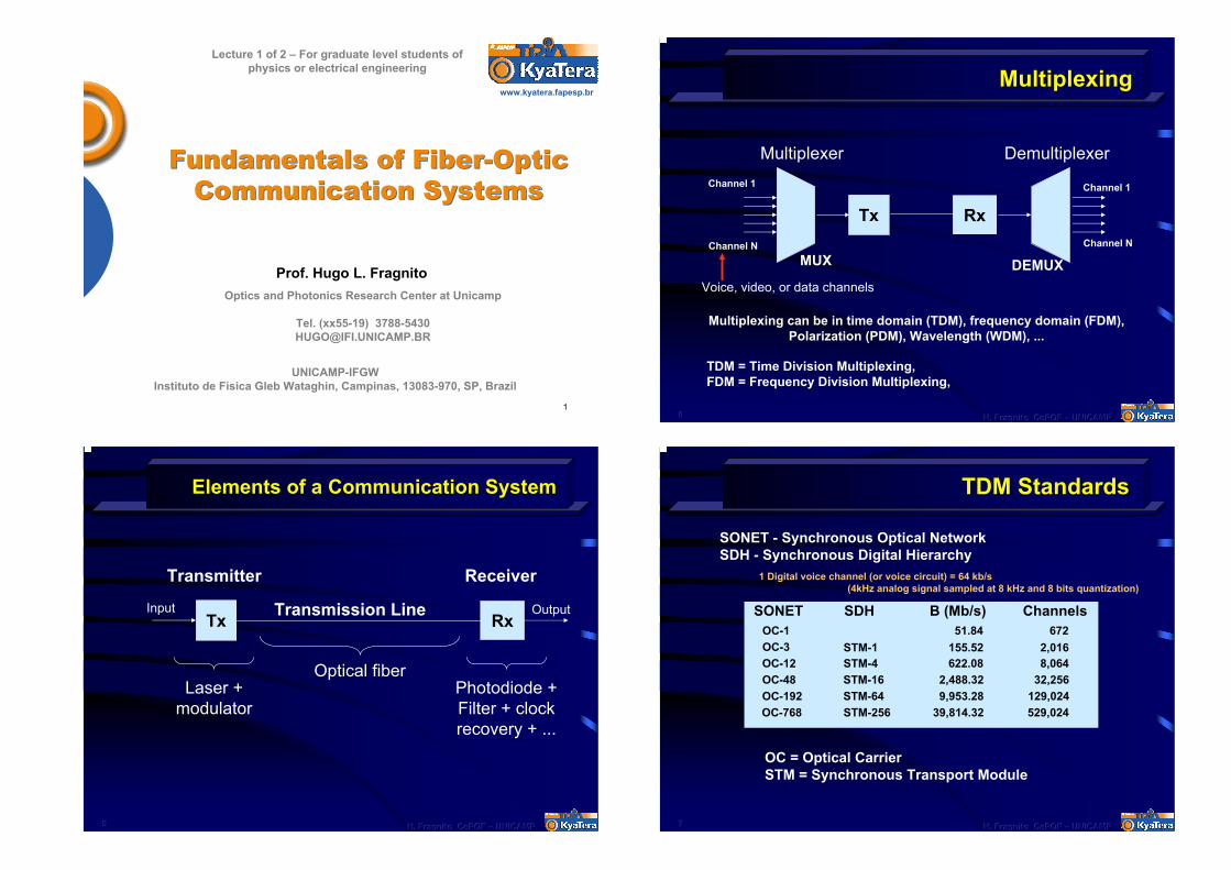
TDM StandardsTDM Standards
SONET - Synchronous Optical Network SDH - Synchronous Digital Hierarchy
1 Digital voice channel (or voice circuit) = 64 kb/s (4kHz analog signal sampled at 8 kHz and 8 bits quantization)
SONET SDH B (Mb/s) ChannelsOC-1 51.84 672OC-3 STM-1 155.52 2,016OC-12 STM-4 622.08 8,064OC-48 STM-16 2,488.32 32,256OC-192 STM-64 9,953.28 129,024OC-768 STM-256 39,814.32 529,024
OC = Optical Carrier STM = Synchronous Transport Module
888 H. Fragnito H. Fragnito H. Fragnito CePOFCePOFCePOF ––– UNICAMPUNICAMPUNICAMP
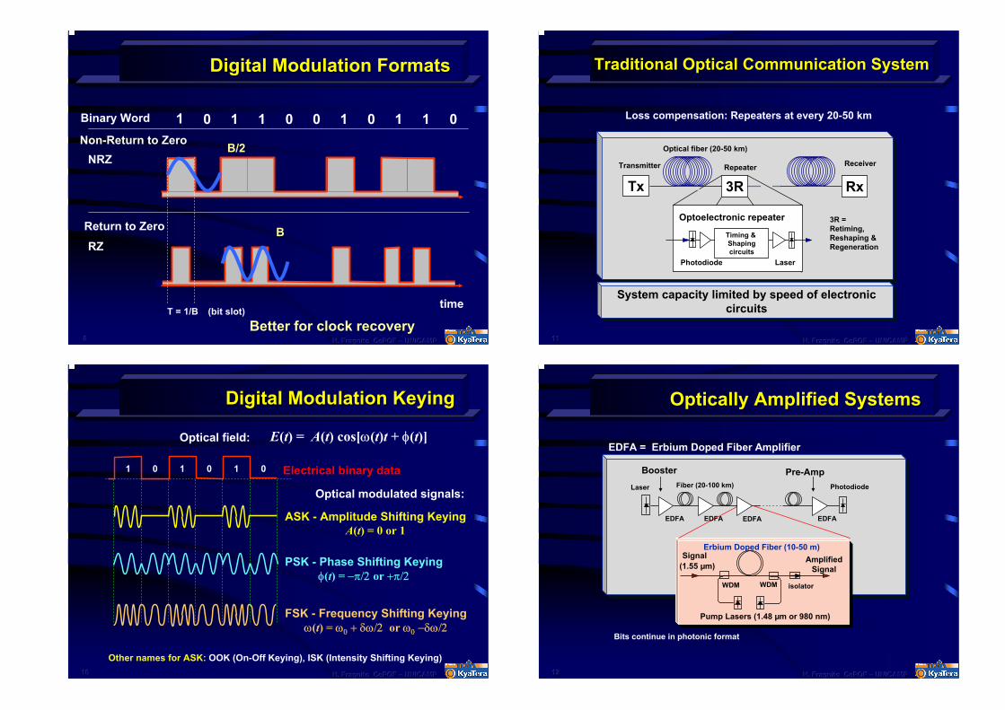
Digital Modulation FormatsDigital Modulation Formats
Binary Word 1 0 1 0 1 1 01 0 0 1
time(bit slot)T = 1/B
Non-Return to Zero
Return to Zero
NRZ
RZ
B/2
B
Better for clock recovery
101010 H. Fragnito H. Fragnito H. Fragnito CePOFCePOFCePOF ––– UNICAMPUNICAMPUNICAMP
Digital Modulation KeyingDigital Modulation Keying
E(t) = A(t) cos[ω(t)t + φ(t)]Optical field:
ASK - Amplitude Shifting KeyingA(t) = 0 or 1
PSK - Phase Shifting Keyingφ(t) = −π/2 or +π/2
FSK - Frequency Shifting Keyingω(t) = ω0 + δω/2 or ω0 −δω/2
1 0 1 0 1 0
Optical modulated signals:
Electrical binary data
Other names for ASK: OOK (On-Off Keying), ISK (Intensity Shifting Keying)
111111 H. Fragnito H. Fragnito H. Fragnito CePOFCePOFCePOF ––– UNICAMPUNICAMPUNICAMP
Traditional Optical Communication SystemTraditional Optical Communication System
Loss compensation: Repeaters at every 20-50 km
Tx
Timing & Shapingcircuits
Transmitter Repeater
Rx
Receiver
Laser
Optoelectronic repeater
Photodiode
Optical fiber (20-50 km)
System capacity limited by speed of electronic circuits
3R
3R = Retiming, Reshaping &Regeneration
121212 H. Fragnito H. Fragnito H. Fragnito CePOFCePOFCePOF ––– UNICAMPUNICAMPUNICAMP
Optically Amplified SystemsOptically Amplified Systems
EDFA = Erbium Doped Fiber Amplifier
Photodiode
EDFA
Laser
EDFAEDFA EDFA
Signal (1.55 µm)
WDM
Erbium Doped Fiber (10-50 m)Amplified
Signal
Pump Lasers (1.48 µm or 980 nm)
isolatorWDM
Booster Pre-AmpFiber (20-100 km)
Bits continue in photonic format
131313 H. Fragnito H. Fragnito H. Fragnito CePOFCePOFCePOF ––– UNICAMPUNICAMPUNICAMP
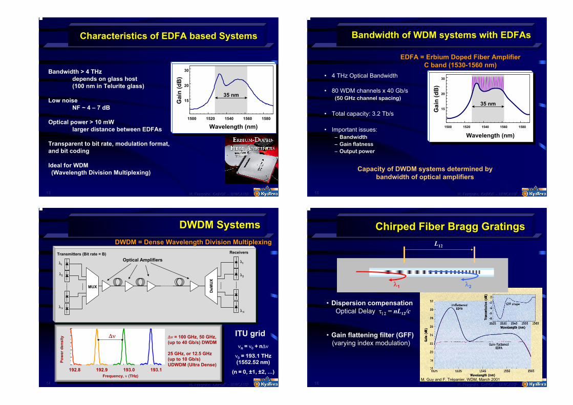
Characteristics of EDFA based SystemsCharacteristics of EDFA based Systems
Bandwidth > 4 THzdepends on glass host(100 nm in Telurite glass)
Low noiseNF ~ 4 – 7 dB
Optical power > 10 mWlarger distance between EDFAs
Transparent to bit rate, modulation format, and bit coding
Ideal for WDM (Wavelength Division Multiplexing)
15
20
30
Gai
n (d
B)
Wavelength (nm)1500 1520 1540 1560 1580
35 nm
141414 H. Fragnito H. Fragnito H. Fragnito CePOFCePOFCePOF ––– UNICAMPUNICAMPUNICAMP
DWDM SystemsDWDM SystemsDWDM = Dense Wavelength Division MultiplexingDWDM = Dense Wavelength Division Multiplexing
Transmitters (Bit rate = B)Optical Amplifiers
λ1
λ2
λN
Receivers
λ1
λ2
λN
MUX
DeM
UX
Pow
erde
nsity
Frequency, ν (THz)192.8 193.0 193.1192.9
∆ν ∆ν = 100 GHz, 50 GHz, (up to 40 Gb/s) DWDM
25 GHz, or 12.5 GHz(up to 10 Gb/s) UDWDM (Ultra Dense)
ITU gridνn = ν0 + n∆ν
ν0 = 193.1 THz(1552.52 nm)
(n = 0, ±1, ±2, ...)
151515 H. Fragnito H. Fragnito H. Fragnito CePOFCePOFCePOF ––– UNICAMPUNICAMPUNICAMP
Bandwidth of WDM systems with Bandwidth of WDM systems with EDFAsEDFAs
• 4 THz Optical Bandwidth
• 80 WDM channels x 40 Gb/s(50 GHz channel spacing)
• Total capacity: 3.2 Tb/s
• Important issues:– Bandwidth– Gain flatness– Output power
15
20
30
Gai
n (d
B)
Wavelength (nm)1500 1520 1540 1560 1580
35 nm
EDFA = Erbium Doped Fiber AmplifierEDFA = Erbium Doped Fiber AmplifierC band (1530C band (1530--1560 nm)1560 nm)
Capacity of DWDM systems determined by bandwidth of optical amplifiers
161616 H. Fragnito H. Fragnito H. Fragnito CePOFCePOFCePOF ––– UNICAMPUNICAMPUNICAMP
Chirped Fiber Bragg GratingsChirped Fiber Bragg GratingsL12
λ1 λ2
• Dispersion compensationOptical Delay τ12 = nL12/c
• Gain flattening filter (GFF)(varying index modulation)
M. Guy and F. Trépanier, WDM, March 2001
171717 H. Fragnito H. Fragnito H. Fragnito CePOFCePOFCePOF ––– UNICAMPUNICAMPUNICAMP
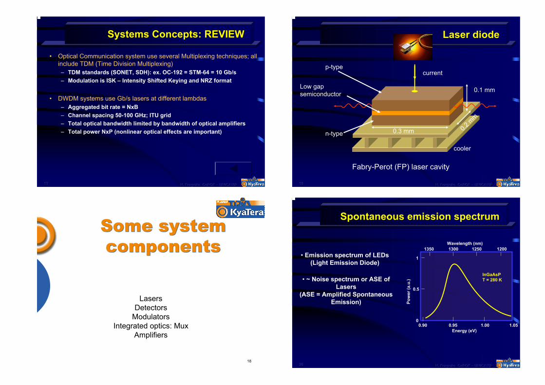
Systems Concepts: REVIEWSystems Concepts: REVIEW
• Optical Communication system use several Multiplexing techniques; all include TDM (Time Division Multiplexing)– TDM standards (SONET, SDH): ex. OC-192 = STM-64 = 10 Gb/s– Modulation is ISK – Intensity Shifted Keying and NRZ format
• DWDM systems use Gb/s lasers at different lambdas– Aggregated bit rate = NxB– Channel spacing 50-100 GHz; ITU grid– Total optical bandwidth limited by bandwidth of optical amplifiers– Total power NxP (nonlinear optical effects are important)
18
Some system componentsSome system components
LasersDetectors
ModulatorsIntegrated optics: Mux
Amplifiers
191919 H. Fragnito H. Fragnito H. Fragnito CePOFCePOFCePOF ––– UNICAMPUNICAMPUNICAMP
Laser diodeLaser diode
p-type
Low gap semiconductor
n-type
current
0.3 mm 0.2 m
m
0.1 mm
cooler
Fabry-Perot (FP) laser cavity
202020 H. Fragnito H. Fragnito H. Fragnito CePOFCePOFCePOF ––– UNICAMPUNICAMPUNICAMP
Spontaneous emission spectrumSpontaneous emission spectrum
1
0
0.5
0.90 0.95 1.00 1.05Energy (eV)
Wavelength (nm)1350 1300 1250 1200
InGaAsPT = 280 K
• Emission spectrum of LEDs(Light Emission Diode)
• ~ Noise spectrum or ASE of Lasers
(ASE = Amplified Spontaneous Emission) Po
wer
(a.u
.)
212121 H. Fragnito H. Fragnito H. Fragnito CePOFCePOFCePOF ––– UNICAMPUNICAMPUNICAMP
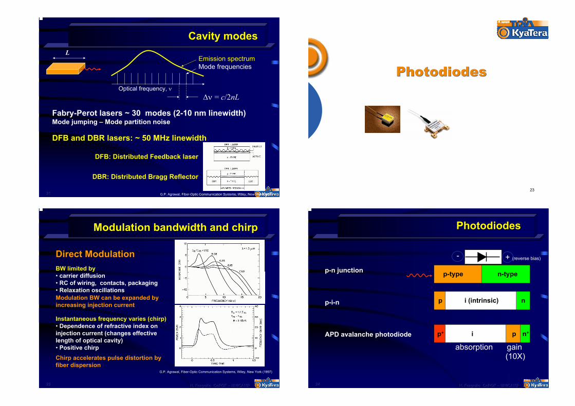
Cavity modesCavity modesL
Emission spectrumMode frequencies
Optical frequency, ν∆ν = c/2nL
Fabry-Perot lasers ~ 30 modes (2-10 nm linewidth) Mode jumping – Mode partition noise
DFB and DBR lasers: ~ 50 MHz linewidth
DFB: Distributed Feedback laser
DBR: Distributed Bragg Reflector
G.P. Agrawal, Fiber-Optic Communication Systems, Wiley, New York (1997)
222222 H. Fragnito H. Fragnito H. Fragnito CePOFCePOFCePOF ––– UNICAMPUNICAMPUNICAMP
Modulation bandwidth and chirpModulation bandwidth and chirp
Direct ModulationBW limited by• carrier diffusion• RC of wiring, contacts, packaging• Relaxation oscillationsModulation BW can be expanded by increasing injection current
Instantaneous frequency varies (chirp)• Dependence of refractive index on injection current (changes effective length of optical cavity)• Positive chirpChirp accelerates pulse distortion by fiber dispersion
G.P. Agrawal, Fiber-Optic Communication Systems, Wiley, New York (1997)
23
PhotodiodesPhotodiodes
242424 H. Fragnito H. Fragnito H. Fragnito CePOFCePOFCePOF ––– UNICAMPUNICAMPUNICAMP
PhotodiodesPhotodiodes
p-type n-typep-n junction
p-i-n
APD avalanche photodiode
+ (reverse bias)-
i (intrinsic)p n
p+ i p n+
absorption gain(10X)
252525 H. Fragnito H. Fragnito H. Fragnito CePOFCePOFCePOF ––– UNICAMPUNICAMPUNICAMP
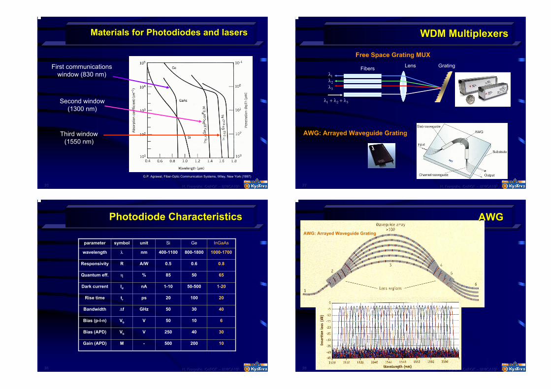
Materials for Photodiodes and lasersMaterials for Photodiodes and lasers
First communications window (830 nm)
Second window (1300 nm)
Third window (1550 nm)
G.P. Agrawal, Fiber-Optic Communication Systems, Wiley, New York (1997)
262626 H. Fragnito H. Fragnito H. Fragnito CePOFCePOFCePOF ––– UNICAMPUNICAMPUNICAMP
Photodiode CharacteristicsPhotodiode Characteristics
parameter symbol unit Si Ge InGaAs
wavelength λ nm 400-1100 800-1800 1000-1700
Responsivity R A/W 0.5 0.6 0.8
Quantum eff. η % 85 50 65
Dark current Id nA 1-10 50-500 1-20
Rise time tr ps 20 100 20
Bandwidth ∆f GHz 50 30 40
Bias (p-I-n) Vb V 50 10 6
Bias (APD) Vb V 250 40 30
Gain (APD) M - 500 200 10
272727 H. Fragnito H. Fragnito H. Fragnito CePOFCePOFCePOF ––– UNICAMPUNICAMPUNICAMP
WDM MultiplexersWDM Multiplexers
Free Space Grating MUXLens Grating
AWG: Arrayed Waveguide Grating
Fibers
λ1 + λ2 + λ3
λ3
λ2
λ1
282828 H. Fragnito H. Fragnito H. Fragnito CePOFCePOFCePOF ––– UNICAMPUNICAMPUNICAMP
AWGAWGAWG: Arrayed Waveguide Grating
29
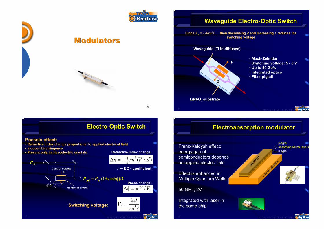
ModulatorsModulators
303030 H. Fragnito H. Fragnito H. Fragnito CePOFCePOFCePOF ––– UNICAMPUNICAMPUNICAMP
ElectroElectro--Optic SwitchOptic Switch
Control Voltage
Pin
l
Pout = Pin (1+cos∆φ)/2V
d
r = EO - coefficient
∆φ = π πV V/
∆n rn V d= − 12
3( / )Refractive index change:
Nonlinear crystal
PockelsPockels effect: effect: •• Refractive index change proportional to applied electrical fielRefractive index change proportional to applied electrical fieldd•• Induced birefringenceInduced birefringence•• Present only in piezoelectric crystalsPresent only in piezoelectric crystals
Phase change:
V drnπλ
= 3lSwitching voltage:Switching voltage:
313131 H. Fragnito H. Fragnito H. Fragnito CePOFCePOFCePOF ––– UNICAMPUNICAMPUNICAMP
Waveguide ElectroWaveguide Electro--Optic SwitchOptic Switch
Since Since VVππ = = λλdd//rnrn33ll, , then decreasingthen decreasing dd and increasingand increasing ll reduces the reduces the switching voltageswitching voltage
V
0
LiNbO3 substrate
Waveguide (Ti in-diffused)
• Mach-Zehnder• Switching voltage: 5 - 8 V• Up to 40 Gb/s• Integrated optics• Fiber pigtail
323232 H. Fragnito H. Fragnito H. Fragnito CePOFCePOFCePOF ––– UNICAMPUNICAMPUNICAMP
Electroabsorption modulatorElectroabsorption modulator
Franz-Keldysh effect: energy gap of semiconductors depends on applied electric field
Effect is enhanced in Multiple Quantum Wells
50 GHz, 2V
Integrated with laser in the same chip
absorbing MQW layers
p-con
tact
p-type
n-type
n-typ
e sub
strate
333333 H. Fragnito H. Fragnito H. Fragnito CePOFCePOFCePOF ––– UNICAMPUNICAMPUNICAMP
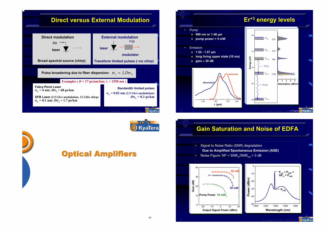
Direct versus External ModulationDirect versus External Modulation
Direct modulationI(t)
laser
External modulationV(t)
laser
modulator
Broad spectral source (chirp) Transform limited pulses (~no chirp)
Bandwidth limited pulsesσλ = 0.02 nm (2.5 Gb/s modulation)
Dσλ = 0.3 ps/km
σ σ λt LD=
Fabry-Perot Laserσλ = 4 nm: Dσλ = 68 ps/km
DFB Laser (2.5 Gb/s modulation, 12 GHz chirp)σλ = 0.1 nm: Dσλ = 1.7 ps/km
Examples ( D = 17 ps/nm/km; λ = 1550 nm )
Pulse broadening due to fiber dispersion:
34
Optical AmplifiersOptical Amplifiers
353535 H. Fragnito H. Fragnito H. Fragnito CePOFCePOFCePOF ––– UNICAMPUNICAMPUNICAMP
ErEr+3+3 energy levelsenergy levels• Pump:
♦ 980 nm or 1.48 µm ♦ pump power > 5 mW
• Emission:♦ 1.52 - 1.57 µm♦ long living upper state (10 ms)♦ gain ≈ 30 dB
Absorption (dB/m)
4F9/2
0.0
0.5
1.0
1.5
2.0
1542
988
810
659
τ = 10 ms
Ener
gy (e
V)
0 2 4 6 8
λ (nm)
4I9/2
4I11/2
4I13/2
4I15/2
τ = 10 µs
1.45 1.50 1.55 1.60
absorption
emission
λ (µm)
H. Fragnito - SBMO-95.ppt
363636 H. Fragnito H. Fragnito H. Fragnito CePOFCePOFCePOF ––– UNICAMPUNICAMPUNICAMP
Gain Saturation and Noise of EDFAGain Saturation and Noise of EDFA
• Signal to Noise Ratio (SNR) degradationDue to Amplified Spontaneous Emission (ASE)
• Noise Figure: NF = SNRin/SNRout > 3 dB
1500 1520 1540 1560 1580-50
-40
-30
-20
-10
0
PASE
Pout + PASE = GPin + PASE
Pow
er (d
Bm
)
Wavelength (nm)-20 -10 0 10 20
0
10
20
30
40
Pump Power 10 mW
30 mW
Gai
n (d
B)
Output Signal Power (dBm)
20 mW
373737 H. Fragnito H. Fragnito H. Fragnito CePOFCePOFCePOF ––– UNICAMPUNICAMPUNICAMP
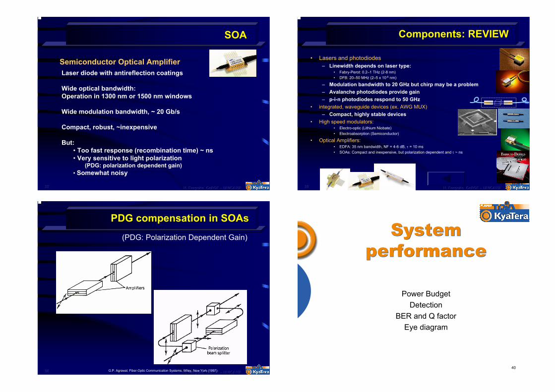
SOASOA
Semiconductor Optical AmplifierLaser diode with antireflection coatings
Wide optical bandwidth: Operation in 1300 nm or 1500 nm windows
Wide modulation bandwidth, ~ 20 Gb/s
Compact, robust, ~inexpensive
But: • Too fast response (recombination time) ~ ns• Very sensitive to light polarization
(PDG: polarization dependent gain)• Somewhat noisy
383838 H. Fragnito H. Fragnito H. Fragnito CePOFCePOFCePOF ––– UNICAMPUNICAMPUNICAMP
PDG compensation in PDG compensation in SOAsSOAs
(PDG: Polarization Dependent Gain)
G.P. Agrawal, Fiber-Optic Communication Systems, Wiley, New York (1997)
393939 H. Fragnito H. Fragnito H. Fragnito CePOFCePOFCePOF ––– UNICAMPUNICAMPUNICAMP
Components: REVIEWComponents: REVIEW
• Lasers and photodiodes– Linewidth depends on laser type:
• Fabry-Perot: 0.2–1 THz (2-8 nm)• DFB: 20–50 MHz (2–5 x 10⁻⁶ nm)
– Modulation bandwidth to 20 GHz but chirp may be a problem – Avalanche photodiodes provide gain– p-i-n photodiodes respond to 50 GHz
• integrated, waveguide devices (ex. AWG MUX)– Compact, highly stable devices
• High speed modulators:• Electro-optic (Lithium Niobate)• Electroabsorption (Semiconductor)
• Optical Amplifiers:• EDFA: 35 nm bandwidth, NF = 4-6 dB, τ = 10 ms• SOAs: Compact and inexpensive, but polarization dependent and τ ~ ns
40
System performance
System performance
Power BudgetDetection
BER and Q factorEye diagram
414141 H. Fragnito H. Fragnito H. Fragnito CePOFCePOFCePOF ––– UNICAMPUNICAMPUNICAMP
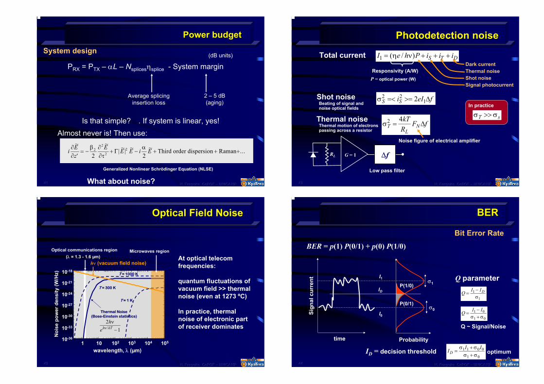
Power budgetPower budget
System design(dB units)
PRX = PTX – αL – Nsplicesηsplice - System margin
2 – 5 dB(aging)
Average splicing insertion loss
Is that simple? . If system is linear, yes!Almost never is! Then use:
i Ez
E E E i E∂∂
β ∂∂τ
α~ ~| ~| ~ ~ ...
′= − + − + + +2
22
2 22 Third order dispersion RamanΓ
Generalized Nonlinear Schrödinger Equation (NLSE)
What about noise?
424242 H. Fragnito H. Fragnito H. Fragnito CePOFCePOFCePOF ––– UNICAMPUNICAMPUNICAMP
Optical Field NoiseOptical Field Noise
Optical communications region (λ = 1.3 - 1.6 µm)
hν (vacuum field noise)
Microwaves region
Noi
se p
ower
den
sity
(W/H
z)
wavelength, λ (µm)1 10 102 103 104 10510-36
10-33
10-30
10-27
10-24
10-21
10-18
Thermal Noise(Bose-Einstein statistics)
T = 1 K
T = 300 K
T = 1000 K
21
heh kT
νν/ −
At optical telecom frequencies:
quantum fluctuations of vacuum field >> thermal noise (even at 1273 ºC)
In practice, thermal noise of electronic part of receiver dominates
434343 H. Fragnito H. Fragnito H. Fragnito CePOFCePOFCePOF ––– UNICAMPUNICAMPUNICAMP
PhotodetectionPhotodetection noisenoise
Total current DTS iiiPheI +++νη= )/(1
Shot noise
Dark currentResponsivity
P = (A/W)
optical power (W)
Thermal noiseShot noiseSignal photocurrent
Thermal noise σTL
NkTR
F f2 4= ∆
RL
Noise figure of electrical amplifier
G = 1
σ σT s>>
Low pass filter
∆f
In practice Beating of signal and noise optical fields
Thermal motion of electrons passing across a resistor
feIiSS ∆>==<σ 122 2
444444 H. Fragnito H. Fragnito H. Fragnito CePOFCePOFCePOF ––– UNICAMPUNICAMPUNICAMP
BERBER
Bit Error RateBER = p(1) P(0/1) + p(0) P(1/0)
Probability
Sign
al c
urre
nt Q parameterI1σ1
IDP(1/0)
P(0/1)
Q I ID=−1
1σ
σ0Q I I
=−+
1 0
1 0σ σI0
Q ~ Signal/Noise
time
ID = decision threshold optimumI I ID =
++
σ σσ σ1 1 0 0
1 0
454545 H. Fragnito H. Fragnito H. Fragnito CePOFCePOFCePOF ––– UNICAMPUNICAMPUNICAMP
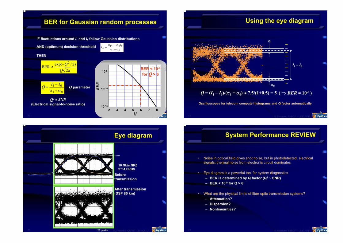
BER for Gaussian random processesBER for Gaussian random processes
IF fluctuations around I1 and I0 follow Gaussian distributions
I I ID =
++
σ σσ σ1 1 0 0
1 0AND (optimum) decision threshold
THEN
π−
≅2
)2/exp(BER
2
2 3 4 5 6 7 810-15
10-10
10-5
Q
BE
R
BER < 10-9
for Q > 6
Q I I=
−+
1 0
1 0σ σQ parameter
Q2 ≈ SNR(Electrical signal-to-noise ratio)
464646 H. Fragnito H. Fragnito H. Fragnito CePOFCePOFCePOF ––– UNICAMPUNICAMPUNICAMP
Eye diagramEye diagram
10 Gb/s NRZ215-1 PRBS
Before transmission
After transmission(DSF 80 km)
25 ps/div
474747 H. Fragnito H. Fragnito H. Fragnito CePOFCePOFCePOF ––– UNICAMPUNICAMPUNICAMP
Using the eye diagramUsing the eye diagram
I1 – I0
σ0
σ1
Q = (I1 – I0)/(σ1 + σ0) ≈ 7.5/(1+0.5) = 5 ( ⇒ BER ≈ 10-7 )
Oscilloscopes for telecom compute histograms and Q factor automatically
484848 H. Fragnito H. Fragnito H. Fragnito CePOFCePOFCePOF ––– UNICAMPUNICAMPUNICAMP
System Performance REVIEWSystem Performance REVIEW
• Noise in optical field gives shot noise, but in photodetected, electrical signals, thermal noise from electronic circuit dominates
• Eye diagram is a powerful tool for system diagnostics– BER is determined by Q factor (Q2 ~ SNR)– BER < 10-9 for Q > 6
• What are the physical limits of fiber optic transmission systems?– Attenuation?– Dispersion?– Nonlinearities?
494949 H. Fragnito H. Fragnito H. Fragnito CePOFCePOFCePOF ––– UNICAMPUNICAMPUNICAMP
Where to get more informationWhere to get more information
• G.P. Agrawal, Fiber-Optic Communication Systems, 3rd ed., Wiley, New York, 2002.
• WDM Solutions, PenWeell, free subscription: www.optoelectronics.world.com
• R. Ramaswami and K. N. Sivarajan, Optical Networks, 2nd ed., Morgan Kaufmann, San Francisco, 2002.
• I.P. Kaminow and T. Li, Eds., Optical Fiber Telecommunications, Vols. III-A, III-B (1997), IV-A and IV-B (2002), Academic Press, San Diego.