Embed Size (px)
Citation preview
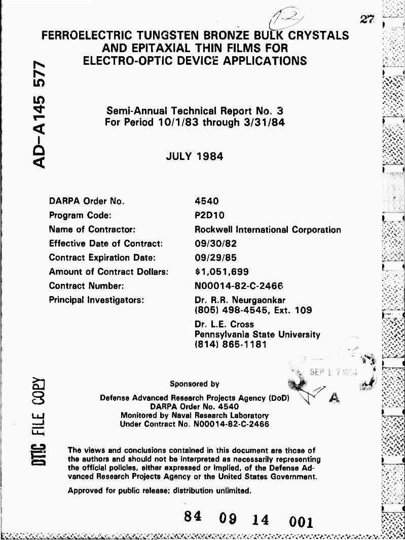
4:^ 27 FERROELECTRIC TUNGSTEN BRONZE BULK CRYSTALS
AND EPITAXIAL THIN FILMS FOR ^ ELECTRO-OPTIC DEVICE APPLICATIONS
in in ^ Semi-Annual Technical Report No. 3 J For Period 10/1/83 through 3/31/84
< JULY 1984
DARPA Order No. 4540
Program Code: P2D10
Name of Contractor: Rockwell International Corporation
Effective Date of Contract: 09/30/82
Contract Expiration Date: 09/29/85
Amount of Contract Dollars: $ 1,051,699
Contract Number: N00014-82-C-2466
Principal Investigators: Dr. R.R. Neurgaonkar (805) 498-4545, Ext. 109
Dr. L.E. Cross Pennsylvania State University (814) 865-1181
' ■• .v.v
.' - ■ =
L
■■ V V
a OLr l
Sponsored by
Defense Advanced Research Projects Agency (DoD) DARPA Order No. 4540
Monitored by Naval Research Laboratory Under Contract No. N00014-82-0-2466
The views and conclusions contained in this document are these of the authors and should not be interpreted as necessarily representing the official policies, either expressed or implied, of the Defense Ad- vanced Research Projects Agency or the United States Government.
Approved for public release; distribution unlimited.
■ A\
84 09 14 001 ■njjjijjjL-i ^VJV^V.'-^V, J'^iÄ^MV'^Ä-^A'^fl'J
bid ■ ^

UNCLASSIFIED MCü«iTv Cl.*S$i»iC*TiON O* TMIS ^*GI ^p-zinss??
REPORT DOCUMENTATION PAGE It «f'OWT SECW^'TV CLASSIFICATION
Unclassified ID ftESTftiCTlVC MARKINGS
U SICUWlTY CLASSIFICATION AUTHORITY
2b OECwASSlFlCATION/DOMNCMAOiNC SCHtOULf
3 OiSTHHUTlON/AVAILAilLlTV OF «EFO«T
Approved for public release; distribution unlimited.
* MMFOIIMING ORGANIZATION MFORT NUMIfRtSl
SC5340.6SA
9. MONITORING ORGANIZATION Rf FORT NUMIERlSI
6«. NAME OF Ff RFORMlNG ORGANIZATION Rockwell International Science Center
IB. OFFICE SYMBOL llf applicant)
7« NAME OF MONITORING ORGANIZATION
Defense Advanced Research Projects Agency
Cc ADDRESS fCl*», Si«i« an« ZIP Codti
1049 Camino Dos Rios Thousand Oaks, California 91360
Tb. ADDRESS (City. Slam and lit Codtl
1400 Wilson Boulevard Arlington, VA 23209
NAME OF FLiNOINC/SFONSORiNG ORGANIZATION
Naval Research Laboratory
•c OFFICE SYMBOL lit applictiiti
9. FRQCUREMENT INSTRUMENT IDENTIFICATION NUMSER
Contract No. N00014-82-C-2466
ADDRESS >Cii>. Slalt and ZIP Coät)
4555 Overlook Avenue S.W. Washington, DC 20375
io SOURCE OF FUNDING NQS
FROGRAM ELEMENT NO
M TiTuE Mdi,» itrunly CJunrictnox/FERROELECTRIC TUNGSTEN BRONZE BULK CRYSTALS AND EPITAXIAL THIN FILMS FOR ELECTRO-OPTIC DEVICE APPLICATIONS
FROJiCT NO
DARPA Order No.
4540
TASK NO
MORK UNiT NO
13. FERSONAL AUTHOR(SI
Cross, Dr. L.E.; Oliver, J.R.; Neurgaonkar, Dr. R.R. I 13A TYFE OF REFORT
Semi-Annual Tech Rpt #3 13D. TIME COVERED
FROM 10/1/83 o 3/31/84 14 DATE OF REFORT lYr . Mo
JULY 1984 Day) II, FAGt COUNT
48 II SuFFLEMENTARY NOTATION
The views and conclusions contained in this document are those of the authors and should not be interpreted as necessarily representing the official policies, either expressed or implied, of the Defense Advanced Research Projects Agency of the U.S. Government.
17 COSATI cooes F'CLD GRQUF ■ Ul OR
-O
II SUBJECT TERMS 'Coilmuf on WMW .,' ntttuan, and idanti^ by Hock numka'i SBN, PBN, PKN, BNN, SNN, Morphotropic Phase Boundary, Tungsten Bronze, Striations, E-O Coefficient, LPE Flux, Dielectric Constant, Writing Sensitivity, Ce, Fe Dopants
• * i
i^/ABSTRACT iCt-nimiiroi Htaftrtfitaatfaan, and lätnlify by bloe» numb*':
"^Several doped (Fe3+ and Ce^+j and undoped SBN:60 single crystals have been grown by the Czochralski tech- nique. Although the quality of doped crystals needs to be improved, they show a considerable enhancement in electro-optic and photorefractive properties, specifically for Cd^-doped SBN:60 crystals. The addition of these impurity species did not change the growth conditions significantly; however, striations were present and became stronger as the concentration of impurity ions increased. Undoped SBN:60 single crystals have also been grown and they are almost striation-free and exhibit excellent electro-optic properties. '
Phase diagram work on the system SrV20g-BaV20e-SrNb20g-BaNb20g has determined that SBN:75 films can be grown from flux compositions which cover a relatively limited range in the phase diagram. Work on the pseudo-binary flux systems BaV^Og-PBN 60 and Pbi_xBaxNb2O6-PBN:60 for PBN film growth has resulted in the formation of the tetragonal PBN phase for one composition, a highly encouraging result.
Research has continued on the pseudo-binary morphotropic bronze systems Ba2NaNb50^5-Sr2NaNb50i5 (BNN-SNN) and Pb2KNb50i5-Ea2NaNb50i5 (PKN-BNN). Improved sintering of ceramic compositions
JO OlSTRlBUTlON'AVAILAHLlTV OF AISTRACT
UNCLASSIFIED/UNLIMITED Q SAME AS RFT. O OTIC USERS O
32i NAME OF RESPONSIBLE INDIVIDUAL
DD FORM 1473, 83 APR
31. ABSTRACT SECLRITV CLASSIFICATION
Unclassified
33b TELEFHONE NUMBER ilntiuit Ana Cod«;
33c OFFICE SYMBOL
COITION OF 1 JAN 73 IS OBSOLETE UNCLASSIFIED SECURITY CLASSIFICATION OF THIS FACE
''• ■■.•.•-•' K '.^o. ■»■ w V "»1 v ', V V VW V V V V W ".'WV »,' i.' V1." V V C •.' \.' VO V ■L" -.*'urV sX>-,l"' "'< fi "'• ""*.''» •\''. '?■■?,

>. *» Rockweil International Science Center
SC534G.6SA
TABLE OF CONTENTS
Page
1.0 SUMMARY AND PROGRESS 1
2.0 DEVELOPMENT OF OPTICAL OUALITY SBN:60 3
2.1 Materials Growth Techniques 3 2.?. Growth Procedure 3 2.3 Growth of Undoped SBN:60 Crystals.; 5 2.4 Growth of Doped SBN:60 Crystals 5
3.0 I.IQUin PHASE EPITAXIAL GROWTH OF BRONZF COMPOSITIONS 12
3.1 Flux Systems for SBN:75 1? 3.2 Flux Systems for PBN:6n 16
4.0 NEW TUNGSTEN BRONZE SYSTEMS FOR ELECTRO-OPTIC STUDIES 20
4.1 Ba2NaNb50i5-Sr2NaNb50i5 System 20 4.2 Pb2KNb50i5-Ba2NaNb50i5 System 25
5.0 OPTICAL EVALUATION OF PBN 29
5.1 Introduction 29 5.2 Exploratory Measurements 30
6.0 EVALUATION OF THE PHOTOREFRACTIVE EFFECT IN DOPED AND UNDOPED SBN:60 34
6.1 Int roduct i on 34 6.2 Photorefractive Measurements 36
7.0 FUTURE PLANNED WORK 41
8.0 PUBLICATIONS AND PRESENTATIONS 42
8.1 Publications 42 8.2 Presentati ons 42
9.0 REFERENCES 43
11 C6160A/sn
^•.^•'^^'^^^^
fl!> Rockwell International Science Center
SC5340.6SA
LIST OF FIGURES
Page
Fig. 1 Ce-doped SBN:60 crystals grown by the Czochralski method 10
Fig. 2 Quaternary phase diagram of the SrO-BaO-f^Og^Og system.... 13
Fig. 3 Quaternary phase diagram of the SrV20g-BaV20g-SrNb20g-BaNb20g systeui 15
Fig. 4 Quaternary phase diagram of the Pb2V207-PbNb20g-BaNb206
system 18
Fig. 5 Quaternary phase diagram of PbV20g-BaV20g-PbNb20g-BaNb20g system 19
Fig. 6 Morphotropic phase boundary conditions for the system BNN-SNN 22
Fig. 7 Dielectric constant (at 10 kHz) vs composition for the system BNN-SNN 22
Fig. 8 Dielectric constant of ceramic S^NaNbgO^ (SNN) as a function of temperature 23
Fig. 9 Morphotropic phase boundary conditions for the system PKN-BNN 26
Fig. 10 Dielectric constant (at 10 kHz) vs composition for the system PKN-BNN 26
Fig. 11 Dielectric constant of ceramic PKN, 0.8 PKN-0.2 BNN and BNN as a function of temperature. Data for BNN is expanded by a factor of 10 for clarity 27
Fig. 12 Structural lattice parameters as a function of composition for PKN-BNN. Note the abrupt discontinuity for the b_ and c_ parameters at the morphotropic 0.75 PKN-0.25 BNN compos i ti on 28
Fig. 13 K vs T measurement along the a, b and c axes of orthorhombic PBN (composition near the morphotropic boundary) 31
iii C6160A/sn
l^s^^^vm^s.^^
K% Rockwell International Science Center
SC5340.6SA
LIST OF FIGURES
Page
Fig. 14 PBN single crystals of composition near the morphotropic boundary. The large areas (A) are free of 90° domains, (B) show good optical quality of the crystals grown in the composition around P^gRaQ^^Oe 32
Fig. 15 Optical conoscopic figure of orthorhombic PBN, c-plate 33
Fig. 16 Experimental set-up for two-beam coupling jxperiments 34
Fig. 17 Absorption spectra of S8N:60-Ce (0,1%) 37
Fig. 18 Absorption spectra of SBN:fiO-Fe (1.0%). = 38
Fig. 19 Absorption spectra of SBN:6n 39
kc
TV C6160A/sn
väKtä&^M&ssZ^

*» Rockwell International Sconce Center
SC5340.6SA
LIST UF TABLES
Table Page
1 Materials for Bulk Single Crystal SBN:60 Growth 4
2 Growth of SBN Single Crystals 6
3 Impurities in Starting Chemicals Used for SBN:60 Crystals.... 7
4 Proposed Dopants for Photorefractive SBN and Other Bronze C rystal s 8
5 Growth Data on Doped and Undoped SBN:60 Crystals 9
6 LPE Fluxes for SBN 14
7 LPE Fluxes for PBN 17
8 Dielectric Properties of Hot-Pressed BNN-SNN 24
9 Optical Properties of Doped and Undoped SBN:60 crystals 40
v C6160A/sn
fl!>
tCi
Rockwell International Science Center
SC5340.6SA
1.0 SUMMARY ANH PROGRESS
The tungsten bronze structural family has been shown to be useful for
a number of applications, including electro-optic, nonlinear optical and pyro-
electric applications. The current work reports the development of optical
quality Sri.xBaxNb;^ (x ■ 0.40) for electro-optic and photorefractive device
studies. Considerable progress has been made in different areas, including
Hyj the growth of doped SBN:60 single crystals and LPE films, as well as electro-
optic and phctorefractive characterization.
Several doped (Fe^4 and Cc?3+) and undoped SBN:60 single crystals have
been grown by the Czochralski technique. Although the quality of doped crys-
tals needs to be improved, they show a considerable enhancement in electro-
optic and photorefractive properties, specifically for Ce^-doped SBN:6n crys-
tals. The addition of these impurity species did not change the growth condi-
tions significantly; however, striations were present and became stronger as
the concentration of impurity ions increased. Once suitable dopants and dop-
ant concentrations are optimized for photorefractive studies, effort will be
extended to improve the crystal quality and size. Dndoped SBN:60 single crys-
tals have also been grown and the quality of these crystals is consistent,
i.e., they are almost striation-free and exhibit excellent electro-optic prop-
erties. In order to improve the optical quality of these SRN:fiO crystals,
higher grade starting materials are now being used for this growth. The
results of this work are promising and will be discussed in our next report.
Extensive work has been performed on the flux systems required for
LPE thin film growth of SBN and pb1_xBaxNb206 (PBN) bronze compositions.
Phase diagram work on the system SrV206-BaV206-SrNb205-BaNb206 bas determined
that SBN.75 films can be grown from flux compositions which cover a relatively
limited range in the phase diagram, and with a relatively high melting point
(> 1350oC). Work on the flux system Pb2V207-Ba2V207-PbNb206-BaNb20fi showed
that only the rhombohedral PBN phase could be precipitated, even when quench-
ing to rjom temperature from 1250oC. It appears that vanadium in the PBN flux
1 C6160A/sn

«> Rockwell International Sci«nce Center
SC5340.6SA
system stabilizes the rhombohedral structure over a much broader temperature
range than is normally encountered for pure PBN, However, work on the pseudo-
binary system BaV205-PBN:60 and Pb^Ba^C^-PENtöO has resulted in the forma-
tion of the ferroelectric tetragonal PBN phase for one composition, and fur-
ther research will be conducted on these systems based on these encouraging
results.
Research has continued on the pseudo-binary morphotropic bronze sys-
tems Ba2NaNb5015-Sr2NaNb5015 (BNN-SNN) and Pb2KNb5015-Ba2NaNb5015 (PKN-BNN).
Improved sintering of ceramic compositions from these systems has resulted in
significantly improved dielectric properties, particularly near morphotropy.
The system PKN-BNN shows particularly dramatic changes in dielectric proper-
ties near the morphotropic 0.75 PKN-0.25 BNN composition, with an abrupt dis-
continuity in the Jr_ and £ lattice paramaters, indicating the potential for
particularly enhanced piezoelectric and electro-optic properties. Single
crystal growth of selected compositions from these systems will be attempted
in the coming period.
i 2 ■ C6160A/sn
^X*QÄ4ftaC^^w^^^^^ö^^^M*^^^^MM*l^^ÄMl^^^^^B^^aS'^Ö,%jMÄ\'k^ü^^^
« Rockwell International Seltne« Center
SC5340.6SA
2.0 DEVELOPMENT OF OPTICAL QUALITY SRN:60
2.1 Materials Growth Techniques
Since most of the bronze compositions grown in our laboratory are
based on solid solution systems, it is important that suitable growth tech-
niques be developed to produce crystals free of optical defects such as stria-
tions, scattering centers and twinning. Striations and other defects are
typical problems common to solid solution crystals, and it is öfter» difficult
to suppress them completely. However, these problems can effective1y be re-
duced such that the crystals can be useful for optical device studies. This
task is difficult; hence, the selection of appropriate growth techniques is
critical in the present work. At present, three different techniques have
been chosen to develop SBN and other bronze crystals. They are as follows:
1. Bulk Single Crystals: Czochralski technique
2. Thin Films: Liquid phase epitaxy (LPE)
3. Strip Crystals Edge defined film-fed technique
The first two techniques are well established in our current work,
and bulk crystals and films of SBN compositions have already been grown. In
the present report, the growth of striation-free SBN crystals and films is
discussed with the associated growth problems.
2.2 Growth Procedure
Nbgflg, SrCOs, Pe203» Ce02 and BaCOß fine powders have been used as
starting materials and weighed out in the desired proportions, as summarized
in Table 1. The ' ^tch mixture is ball-milled in acetone for 20-30 h, and then
poured into a large drying dish. The dried powder is placed in a platinum re-
action dish and calcined at 1000oC for 10-15 h to eliminate carbonates and any
possible carbon from the pyrolytic breakdown of residual acetone. The cal-
cined powder is then ball-milled and refired in an oxygen flow of 2 cfh at
3 J C6160A/sn I I I

f» Rockwell International Science Center
SC5340.6SÄ
1400oC for about 4-6 h. Phase checks and x-ray lattice constant measurements
are made for each batch to ensure the use of a phase-pure bronze composition
for crystal growth, A thick-walled platinum crucible of 2 x 2 in. in dimen-
sion is used for this growth, and this container holds roughly 450 g of melt
composition.
Table 1
Materials for Bulk Single Crystal SBN:60 Growth
Crystal Composition Starting Materials Conditions and Remarks
SBN:60 a. SrC0| b. RaC03 c. Nb2n5
Total Wt. Growth Wt.
SRN:60 + Fe3+ a. SrCOs b. RaCOa c. Nb205 d. Fe203
Total Wt. Growth Wt.
SBN:60 + Ce3+ a. SrCOs b. BaCOa c. Nb2n5 d. Ce02
Total Wt.
Growth Wt.
135.OR gms 115.4fi gms 398.73 gms
649.26 gms 450.00 gms
135.OR gms 115.48 gms 398.73 gms
1.98 gms
651.24 gms 450.00 gms
135,08 gms 115.48 gms 398.73 gms
1.00 gms
650.26 gms
450.00 gms
* Congruent melting composition * Large crystals can be grown * Large electro-optic
coefficient (raa) * Melts at 15l0oC * Crack-free and optical quality
* Dielectric and electro-optic coefficient increased
* Growth of large crystals is possible.
* Enhanced photorefractive properties
* Crack-free crystals
* Dielectric and electro-optic coefficient improved
* Growth of large crystals is possible
* Enhanced photorefractive properties
* Crack-free and optical quality crystals
C6160A/S'
iAuW^C>L.''>C*yy!»J1S>^.^^

*1"> Rockwell International SckMice Canttr
SC5340.6SA
2.3 Growth of Undoped SBN:60 Crystals
As summarized in Table 2, we have grown a number of undoped SBN:6n
single crystals of excellent quality by the Czochralski technique. The qual-
ity of these crystals is generally excellent and the process appears to be
highly reproducible for this composition. Since the ADC system is now well
established to control the striation problem more effectively, we have begun
to introduce a few more changes in the current system to improve the crystal
quality further.
Recently, we found that small amounts of impurities have a drastic
photorefractive effect in optical waveguide applications. Current optical
measurements at NRL on SBN:fin crystals indicate that the elimination of impur-
ities should significantly improve the optical quality for waveguide applica-
tions. In view of this, higher grade starting materials have been used in the
present growth experiments (Table 3). Although minor changes in thermal gra-
dients have occurred, this batch has been used to successfully grow two new
SBN:60 crystals. The quality of these crystals is significantly better, and
it is expected that by controlling the thermal gradients more effectively, it
should be possible to further control the optical quality in these crystals.
We expect that during the next six month period, we should have a sufficient
number of crystals to analyze the crystal quality and thereby further refine
the growth technique.
2.4 Growth of Doped SBN:60 Crystals
Since the optical quality and performance of SBN:60 crystals contin-
ues to be improved, it is important that other factors such as speed and sen-
sitivity be enhanced for this family of crystals. Besides the further devel-
opment of striation-free crystals, we have begun to examine the effects of
5 C6160A/sn
^Mll!&^^^^

w Rockwell International Sconce Center
SC53Ä0.6SA
Growth of ! Table ? JBN Single Crystals
To Boule NRL No.
Date Grown
Boule Wt. gn
Boule Size, cm
Dip CC)
Pull Rate Bin/hr
, Rotation rpm
_ — ,
Remarks, ObservaMons
167» 11/1/83 20 1.2 x 3.0 1492 ~ 9 - 5 Basal «nd vertical cracks, two deep twins, deep green color
168* 11/4/83 30 1.2 x 4.8 1492 9-10 ~ 6 Basal and vertlce! cracks, but no twins
169* 11/10/83 27 1.2 x 4.0 1492 8-10 5-6 Uncracked upon cutting, green i color, dopant distribution uneven
170* 1/6/84 6 1.0 x 1.8 1492 5-10 12-15 Some twins and cracks, dark pink color, 1 l^" x 1 1/4' crucible |
171 1/18/84 4 0.5 x 4.5 1492 4-9 10 Uncracked, pink color, good diameter control, striae closer together
172 1/20/84 - 6 0.6 x S.C 1492 6-9 12-20 Uncracked, pink color, diameter [ control by pull rate variation
173 1/31/84 21 1.2 x 5.0 1492 8-10 15-20 New charge, good widening cone, some cracking upon seed removal
174 2/3/84 22 1.5 x 3.5 1491 4-10 - 15 Crack, defects from epl join
* 175 2/7/84 25 1.4 x 3.0 1492 - 6 15 Uncracked. reversed seed dip j end, good widening cone
176 2/9/84 31 1.5 x 3.0 1492 - 6 8 Uncracked, straight growth
* 177 2/14/84 46 1.9 x 3.0 1490 ~ 6 10 Uncracked, minor coring down j c-axls j
178* 3/16/84 30 1.5 x 4.0 1490 ~ 6 3-8 Minor surface twinning, deep 1 green color
179* 3/20/84 22 1.5 x 4.3 1488 ~ 6 6-12 Uncracked, coffee color
180 3/27/84 2? US x 4.3 1488 - 6 ~ 8 Uncracked, same color as 179, tendency to twin beyond 1.5 cm diameter
181 4/4/84 44 1.9 x 2.6 1495 ~ 6 - 8 Taken from furnace uncrackt i but cracks upon cutting j
182 4/17/84 37 1.6 x 3.0 1492 5-8 ~ 8 Cracks upon seed removal, grew a bit off c-axls |
183 5/8/84 26 1.4 x 3.0 1488 6-8 ~ 6 Uncracked, minor coring
184 5/15/84 37 1.7 x 3.0 1490 6-8 • 6 Seed section heavily defeated (by itch pit observation) near edge. Removed uncracked from furnace
Not« Is »11 erysUls grown In Oj flow of ~ 4 S.C.F.H. Note 2: »11 erysUls grown were of composition Sr/B* of 0.61/0.39.
• Doped SBN:60 single erysUls.
C6160A/sn
.•»^l'^^Vöv.^v/^^^
* Rockwell international Sci«nc« Center
SC534n.fiSA
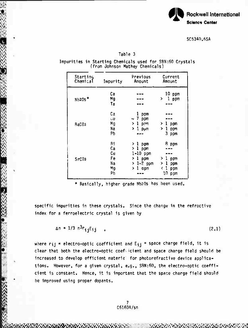
Table 3
Impurities in Starting Chemicals used for SBN:60 Crystals (from Johnson Mathey Chemicals)
Starting Previous Current Chemical Impurity Amount Amount
Ca mmm 10 ppm Nb2n5* Mg ... > 1 ppm
Ta —- ---
Ca 1 ppm ...
wU ~ 7 ppm RaC03 Mg > 1 pnm > 1 ppm
Na > 1 ppm > 1 ppm Pb mmm 3 ppm
Ri > 1 ppm 8 ppm Ca > 1 ppm -~ , Cu 1-10 ppm —
SrC03 Fe > 1 ppm > 1 ppm Na > 1-2 ppm > 1 ppm Mg > 1 opm < 1 ppm Pb —- 10 ppm
* Basically, higher grade Nb205 has been used.
specific impurities in these crystals. Since the change in the refractive
index for a ferroelectric crystal is given by
An = 1/3 n3r1.j(:ij (2.1)
wnere nj a electro-optic coefficient and Eij ■ space charge field, it is
clear that both the electro-optic coef.-cient and space charge field should be
increased to develop efficient materü for photorefractive device applica-
tions. However, for a given crystal, e.g., SRN:60, the electro-optic coeffi-
cient is constant. Hence, it is important that the space charge field should
be improved using proper dopants.
C6160A/sn
f^fS^^ÄÄ^Ä^;: mämmmmg^mMmmmmmomamasm
• Rockwell International Science Center
SC5340.6SA
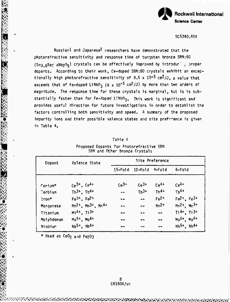
Russianl and Japanese^ researchers have demonstrated that the
photorefractive sensitivity and response time of tungsten bronze SRN:60
(Sro.eBac 4^205) crystals can be effectively improved by introdur" v proper
dopants. According to their work, Ce-doped SBN:60 crystals exhibit an excep-
tionally high photorefractive sensitivity of 9.5 x 10⁻³ cm2/J, a value that
exceeds that of Fe-doped LiNbOß (4 x 10'5 cm^/J) by more than two orders of
magnitude. The response time for these crystals is marginal, but is is sub-
stantially faster than for Fe-doped LiNbf^. This work is significant and
provides useful direction for future investigations in order to establish the
factors controlling both sensitivity and speed. A summary of the proposed
impurity ions and their possible valence states and site pref'-'-ence is given
in Table 4.
TaMe 4
Proposed Dopants for Photorefractive SRN SRN and Other Bronze Crystals
Dopant Valence Stal .e Site Preference
15-Fold 12-Fold q-Foid 6-Fold ]
i rerium* Ce3+. Ct4+ Ce3+ Ce3+ Ce4+ Ce4+
1 Terbium Tb3+. Tb4+ Tb3+ Tb4+ Tb4+
Iron* Fe3+, Fe2+ — Fe2+ Fe2+, Fe3+
\ Manganese Mn2+, Mn3+, Mn4+ — Mn2+ Mn2+, Mn3+ \
Titanium Mi4+, Ti3+ — — Ti4+, Ti3+ i
1 Molybdenum Mo5+, Mo4+ -- — M06+, Mo4+ |
Mi obi UP1 Nb5+, Nb4+ MB — Nb5+, Nb4+ |
Used as Ce02 a.id Fe203
8 C6160A/sn
-;V^^\S'X\S^N-:>*.^<S"^^>I^
* Rockwell International S^nce Center
SC5340.6SA
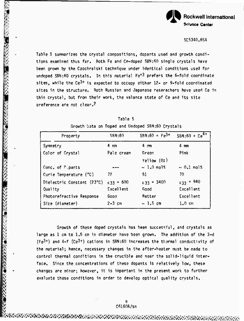
Table 5 summarizes the crystal compositions, dopants used and growth condi-
tions examined thus far. Both Fe and Ce-doped SBN:fiO single crystals have
been grown by the Czochralski technique under identical conditions used for
undoped SBN:60 crystals. In this material Fe+3 prefers the 6-fold coordinate
sites, while the Ce3+ is expected to occupy either 12- or 9-fold coordinated
sites in the structure. Both Russian and Japanese reserachers have used Ce in
this crystal, but from their work, the valance state of Ce and its site
oreference are not clear.2
Table 5
Growth liata on Doped and Undoped SBN:60 Crystals
Property SBN:60 SBN:60 + Fe3+ S8N:60 + Ce4+ 1
Symmetry 4 mm 4 mm 4 mm
Color of Crystal Pale cream Green
Yellow (02)
Pink
Cone, of P.,pants ... ~ 1,0 mol% ~ 0,1 mol%
Curie Temperature (0C) 7? 51 70
Dielectric Constant (230C) e33 ■ 600 £33 = 3400 £33 " 9d0
Quality Excellent Good Excellent
Photorefractive Response Gooo Better Excellent i
Size (diameter) 2-3 cm ~ 1,5 cm 1,0 cm I
•J Growth of these doped crystals has been successful, and crystals as
large as 1 cm to 1,5 cm in diameter have been grown. The addition of the 3-d
(Fe3+) and 4-f (Ce3+) cations in SBN:60 increases the tharmal conductivity of
the material; hence, necessary changes in the after-heater must be made to
control thermal conditions in the crucible and near the solid-liquid inter-
face. Since the concentrations of these dopants is relatively low, these
changes are minor; however, it is important in the present work to further
evaluate these conditions in order to develop optical quality crystals.
Cfil60A/sn
^^^^<>i^^^^^m^^

* Rockwell International Science Center
SC5340.6SA
The Fe-doped SBN:60 crystals are deep green in color; however, this
color changes to a deep yellow after annealing in an oxygen atmosphere at
1000oC. This result indicates that at elevated temperatures Nb5+ reduces to
Nb^+, which is again a tr iition metal ion and contributes to the color of
the crystal. The Ce-doped SBN:60 crystals show a pink color which persists
after oxidation at 1000oC.
Fracture-free and reasonably good quality crystals have been grown.
Although the growth of bigger sized crystals is possible in the present set-
up, the technique at present will be confined to smaller size crystals.
Figure 1 shows typical Ce-doped SBN:60 single crystals grown along the c-axis.
Once the initial electro-optic and photorefractive properties of these doped
crystals are established, plans will be made to improve their size and qual-
ity. X-ray diffraction studies show that crystal habit for these doped crys-
tals is similar to undoped crystals, and is based on 24 facets of four prisms:
(110), (120), (100) and (130).
Fig. 1 Ce-doped SRN:60 crystals grown by the Czochralski method.
10 C6160A/sn

* Rockwell International Science Center
Mj ' SC5340.6SA .' s •V
,>^ „ optical evaluation of doped SBN:60 crystals indicates the presence of 6N weak striations which are basically connected to the addition of Fe3+ and Ce3+
y cations. It is believed that these striations can be suppressed or partially |i removed h> controlling the thermal gradients in the crucible and near the vj,; solid-liquid interface. This task will be undertaken only when the dopant M concentration is optimized. As shown in Table 5, the addition of Fe3+ and H Ce3+ cations has significantly enhanced the dielectric constant, which indi-
cates an increase in the electro-optic coefficient (r-j-j) in similar propor-
tions. It was also found that the photorefractive sensitivity was substan- tially increased with dopants. These results are discussed in Section ß.O.
Based on all of these observations, we expect that by optimally con- trolling dopant concentrations in SBN:fiO crystals, it should be possible to effectively investigate both photorefractive sensitivity and speed. During the next six months, the following experiments will be tried for photorefrac-
tive applications. The are as follows:
• Establish valance states of Fe and Ce cations in SBN:6n crystals.
• Establish optimum concentrations of Fe and Ce necessary for increased photorefractive sensitivity and speed,
• Establish the dielectric and electro-optic properties for these doped crystals and their effects on photorefractive properties.
• Develop more SBN:fiO crystals with varying dopant concentrations.
11 C6160A/sn
AV>C^X^>^^*>;hyv %>A0>*
• Rockwell International Science Center
-*.'
SC5340.6SA
3.0 LIQUID PHASE EPITAXIAL GROWTH OF BRONZE COMPOSITIONS
Large tungsten bronze single crystals are often very difficult to
grow by the Czochralski method, particularly in the case of incongruently
melting compositions (e.g., SBN:75) and compositions with volatile constituent
ions (e.g., Pb^* in Pbi.xBaxNb205). In such cases, an alternative growth
method is the liquid phase epitaxy (LPE) technique, which can be used to de-
velop optical quality tungsten bronze thin films using existing bronze single
crystal substrate. This technique is important not only for thin film fabri-
cation for electro-optic, nonlinear optic and piezoelectric device applica-
tions, but also in the development of new bronze compositions for property
evaluation.
The present work has focused on the development of LPE films of the
tetragonal bronze compositions SBN:75 and PBN:60. Since large single crystals
of SBN:50 and SRN:60 are available for use as substrate material with minimal
lattice mismatch to the LPE bronze compositions, we do not anticipate any
major problems in actual film growth. However, successful film growth of fhese selected compositions is inherently dependent on the thermodynamics of
the flux systems used, with the three major requirements being (1) a suffi-
ciently low melt temperature, (2) the absence of second phases, and (3) the
maintenance of the desired bronze composition in the as-grown film. The re-
sults of our current work are discussed in the following section.
3.1 Flux Systems for SBN;75
As discussed in a previous report, we have successfully demonstrated
the LPE growth of SBN:60 thin films on SBN:60 substrate using a BaV206- Sr0.5Rao.5Nt>?06 flux system. However, in the case of SBN:75 thin film growth,
a composition which displays the highest electro-optic and piezoelectric co-
efficients in the SBN family, we did not know the proper flux recipe required
in order to maintain compositional control over the as-grown film. Therefore,
the present work has focused on the quaternary phase diagram for the SrO-BaO-
12 C6160A/sn
l^j^Mwi^a^aBfA-^^^^

• Rockwell International Science Center
SC5340.6SA
Nb205-V205 system in order to understand its thermodynamic behavior. Because
of the extensive work required to build the entire quaternary phase diagram,
our work has been restricted to possible bronze-forming flux systems such as
BaV206-Sro.5Bao.5Nb206, SrV206-Sro.5Bao.5Nb206. and (.65) Sri,xBaxNb206- (.35)Sro.5Bao.5Nb206. The ranges covered in the quarternary phase diagram
with these systems are shown in Fig. 2.
A variety of flux compositions were prepared and then sintered or
melted at either 1000oC or 1250oC. After leaching away the remaining vana-
dates with a dilute nitric acid solution, the structures of the remaining
niobate solids were identified using powder x-ray diffraction measurements and
analysis. The results of this work are presented in Table 6,
•CS42«97
V205
65/35
8rV206
Nb205
B»Nb206
BaO
Fig. 2 Quaternary phase diagram of the SrO-BaO-Nb2n5 system.
13 C6160A/sn
^>^: s^.>>: ^>>^^^:^^^:^^
fs &
Rockwell International Science Center
SC5340.6SA
1
a: cc uo
L. o
1*-
Oi «/> JZ
0) V
fD 9
I
vc
CSJ JD z
u> u c VO VO to vc •i- fti o c» r«. o 00 o C t/1 <v b t. i_ CO CO CM + in X CM
••- HJ XI u o> S • • X • * • • x rex: z £ x: x z z z Jg z z 2 E Q. b S -t-1 ■U CD cc k cc cc CD (.
to o O to in to tn «n to to or
c in
o in s
0) o o o o c o c CM CM o CM t. c o o o o o U1 i—I <—l m rl 3 o o o o o c CM CM
4-> re —
rH t-t 1—1 f-H 1—1 f-l •-H 1 1 l-H 1 Oio 1 i 1 "S Y ■c i 1 L,
01 b o 1 01
Q.»^ ••-> ■t-" *i *J *J 4-> 4-1 +J ■<-> 4-1 4-*
1 ^— ^— pv r— f— ft— ^— c c r— C gl 01 o QJ o o o •r- •I" o N* 1
t- s: z s: X r T 5: to to r to
re CD
\n in in i ♦ CSJ o vo o «3- p~- o m in c c
oc m ro ro CSJ I-H r^. vc vc CO in \ (. • • • • • « • « * • • i to c o c c c o o o c c O
V. (. Irt
O CM
c CNJ
VO o
CVJ
VO c CM ^1 JZ £ x; X
z z z z ^1 in in in in • • • • • I c c c c ©
VO re re re fD VC VC VC vo VC re o oc cc ee cc c c O c c cc CM in in in in CM CM CM f^ CM in
£> • • • • JC £ X X X • I Z o c c c Z z z z z c in u t~ 1- l- in in in in in t-
^ c • to to to to • • e • • to ^ o c o c; o c c 1 «^ re »< >« «* *t re re re re re u i v a LO in in LO cc c: cc cc cc c I «^ ir> P0 CO CO CO m in m in IT m i v> • • • • • e
c + + + + o o c o o + " c c u t- C b
i § to lO *o vc VC to to to to in vo o o o C 0
o t« CM CM CM CM >« (ft »< § o Cvj
m > > > > in p o > ro m
• r-- 00 • cr
• CO VO r*. fv vo m
+ o re
o re
o re
o re
+ + + •k + ■o re
«c cc cc CO CD VO vo vo VC VO CD o in m m i-H o c o o c in evj • • • t CM CM CM CM CM e
> c o o o > > > > > o b. L. C it b re t. b b re t.
CO lO to to to CD to <n to CD to
»« »« H »« »« »« »I »« § »« *t in in m in in in o o o c <c> in vo vo vo VO «» CO CM «• in
• i-< CM CO ^t in VC r» oc Oi o '_, 0 I—1 .—i
1 z
14 C6160A/sn
5
^^^CiÄÄCv^Äv^.. j^^^-S^i^<i^'>^i^-^^
• Rockwell International Science Center
SC5340.6SA
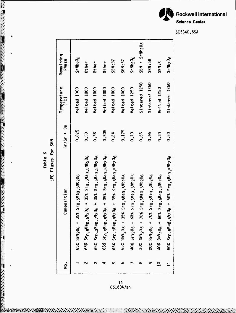
Figure 3 shows the phase diagram for the system SrV206-BaV20fi-
SrNb206-BaNb206, which is the smaller quaternary region examined here in the
larger Sr0-Ra0-Nb205-V205 phase diagram of Fig, 2. The solid circles in Fig,
3 represent tetragonal tungsten bronze SBN phases, and the squares represent
other observed phases according to the results listed in Table 6. From this
work, it is seen that only in the shaded regon of Fig, 3, which includes the
flux compositions No, 5, 6, 9 and 10, can single phase bronze compositions be
found. The range of this bronze forming region for Sr^Bax^Os is
0.25 < x < 0,75, as shown in Fig, 3.
SrV206
V/V + Nb
.1-2^0C 40%
1B000C Ü 1—
IBOCC i Ü
8rNb206 76% 68% 60% 37% 26% BaM^Oe
Sr/Sr-t-B«
• T.B.
D OTHERS
B T.B. + OTHERS
Fig. 3 Quaternary phase diagram of the SrV206-BaV206-SrNb206-BaNb206 system.
15 C6160A/sn
W^ttl^'^Z^
* Rockwell International Science Center
SC5340.6SA
At the present time, there is sane uncertainty in the determination
of the actual SBN compositions formed in this region. However, since we were
able to establish that SBN:37 was grown from flux No. 6 and SBN:58 from flux
No. 9, two tie-Tines can be drawn from these flux points in the phase diagram
shown in Fig. 3 (dashed lines). Hence, in order to grow LPE films with the
composition Srot75Bao.25Nb206, we must work in the very small region of flux
compositions bounded by the SBN:58 tie-line.
Considering the melting points for various flux compositions, e.g.,
roughly 1000oC for V/(V+Nb) = 0.65, 125n0C for V/(V+Nb) = 0.40 and 1500oC for
V/(V+Nb) = 0, it is clear that the LPE growth of the SBN:75 bronze composition
from the Sr0-Ba0-Nb205-V205 flux system may not be particularly easy. Not
only must one deal with a relatively narrow range of suitable flux composi-
tions, but also a necessarily high flux melting point greater than 1350oC.
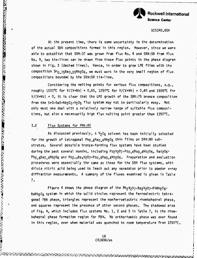
3.2 Flux Systems for PRN:60
As discussed previously, a V205 solvent, has been initially selected
for the growth of tetragonal Pbo,6Bao.4Nh206 thln fl"1,ns on SBN:60 sub-
strates. Several possible bronze-forming flux systems have been studied
during the past several months, including Pb2V207-Pbo.6Ra0.4Nb20ß, Bav20f- Pb0.6Ba0.4Nb206 and Pb2-xBaxV207-Pbo.6Bao.4Nb206. Preparation and evaluation
procedures were essentially the same as those for the SBN flux systems, with
dilute nitric acid being used to leach out any vanadates prior to powder x-ray
diffraction measurements. A summary of the fluxes examined is given in Table
7.
Figure 4 shows the phase diagram of the Pb2V207-Ba2V207-PbNb206-
BaNb206 system in which the solid circles represent the ferroelectric tetra-
gonal PBN phase, triangles represent the nonferroelectric rhombohedral phase,
and squares represent the presence of other second phases. The shadowed area
of Fig. 4, which includes flux systems No. 1, 2 and 5 in Table 7, is the rhom-
bohedral phase formation region for PBN. No orthorhombic phase was ever found
in this region, even when material was quenched to room temperature from 1250oC.
16 C6160A/sn
^•■■v .-;^'^^^y-^>.v^v.-.v,-v.^v^..-..-^^.-.^^^y-.,^^,^,.,.1 ri 1[rT | 11 ^

'i* Rockwell International Science Center
SC5340.6SA
01 B
.1- a; c vt
•<- m rex: I* a
o. I we; CO
a;
ÜB re
a: a.
o
in
X 3
re
D.
XI a.
c o
o Q.
O
CC oc cc vc a a CL sc 0
ec CM CO • • • a. x Ok XI X! u (. x: u S 1 1 a«
x: 0)
JC 01 X «5
• x: £ 4-> ■»J £ £ w 0) cz es O 0 Of t- + H-
0 c c 0 0 c O 0 c 0 0 in 0 c IT) 0 c c c CM 0 c CM -M O ^0 1-H t—1 —1 ^H I-< t—1
in \r> *M A CM fl • * fl D *
"C •-' ■O .—1 •0 •c ■c •c ■D "D fi 0) 01 0) 01 01 O O *-> "B 4J -D ••-> 4-> 4-> ■t-) 4-> ■4->
»- c p^- c pa— f~ p— ^- p— F" Oi re 01 re OJ 0) 0' 0 i1 A zr T X z: s: z- S z
C5
vc c CM X z:
c <e
cc fl
o X) Ou
o
o CM > CM Xi
g
O VC
VC o CM X
c re
cc VC * e x
CL
C
O CM' > 00 • o re ec CM
X a. »« o
CM
o
vc c
CM X5
o re CC vc c X Q.
t« o
c CM > CM
re CO 00 • o X) CL
o
n
vc o CM X
c re cc VC • c a.
PO
o CM
re cc to
• o
O-
o vc
1^. oc
c <-•
o
VC c vc CM' C Xi CM Z £ «■ S
c re ec vc • o
x> o. »*. c IC
o re
oc VC
o X a.
g CM
+ O vc CM O > CM CM > £ re a. cc
** S5 o o in oc
UD vc
vc o CM X zr
• c re cc vc
• o X a.
§
vc O CM > re oc
g
VC o
CM' X
c re cc VC • c X a
IT)
VC O CM > re cc
in
00
17 C6160A/sn
iiairtW vi* vsis % •:v'X{-.-:v'^Xv<vfN<sfsXvLii:%^
fl» Rockwell International $ci«nce Center
^2^20?
SC5340.fiSA •CMlUt«
••2V207
PbNb206 B»Nb206
• TET PBN
A RHOM PBN
D OTHERS
Fig. 4 Quaternary phase diagram of the Pb2V207-Ba2V207-PbNb206-RaNh206 system.
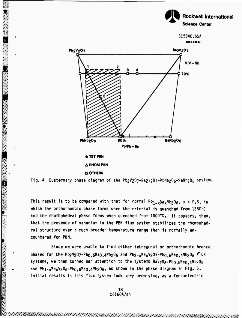
This result is to be compared with that for normal pt)1.xBaxNb206, x < 0.6, in
which the orthorhombic phase forms when the material is quenched from 1250oC
and the rhombohedral phase forms when quenched from 1000oC, It appears, then,
that the presence of vanadium in the PBN flux system stabilizes the rhombohed-
ral structure over a much broader temperature range than is normally en-
countered for PBN.
Since we were unable to find either tetragonal or orthorhombic bronze
phases for the Pb2V207-Pbo,6Bao.4Nb206 and Pb2-xBaxV207-Pbo,6Bao.4Nb206 ^ux
systems, we then turned our attention to the systems BaV206-Pbo.6Ban.4Nb206
and Pbi.xBaxV206-Pbo,6Bao.4Nb205, as shown in the phase diagram in Fig. 5.
Initial results in this flux system look very promising, as a ferroelectric
18 C6160A/sn
wfrL>^vD!^vC^i^«ÄÄK^
* Rockwell International Sconce Center
SC5340.6SA
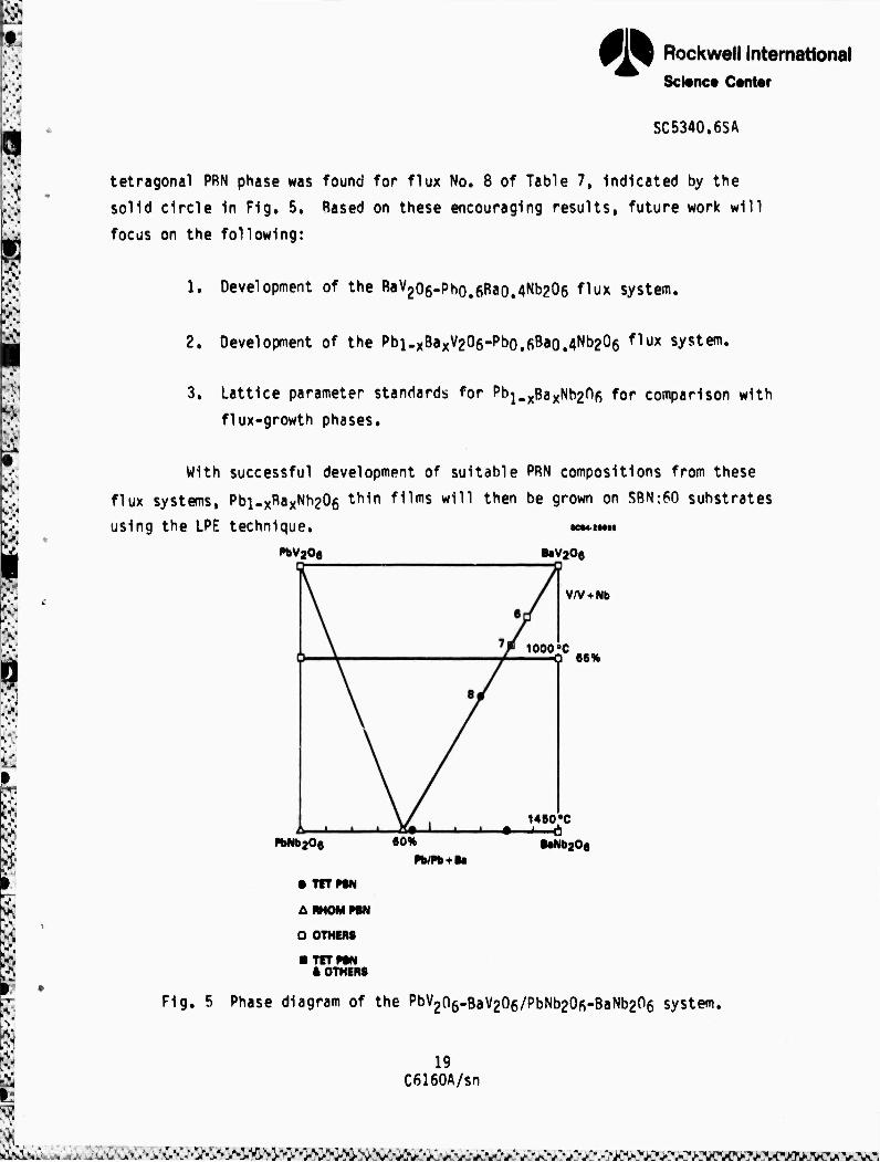
tetragonal PBN phase was found for flux No. 8 of Table 7, indicated by the
solid circle in Fig, 5, Rased on these encouraging results, future work will
focus on the following:
1. Development of the BaV2o6-Pho.6Rao.4Nb206 flux system.
2. Development of the Pbi-xBa^Oe-Pbo.fiBao.A^Oe f1ux system.
3. Lattice parameter standards for Pb^Ba^b^nf, for comparison with
flux-growth phases.
With successful development of suitable PRN compositions from these
flux systems, Pbi.xRaxNb206 thin films will then be grown on SBN:fO substrates
using the LPE technique. KM».»
PbV20e BaVjOe
V/V + Nb
lOOO'C —0 66%
«»NbaOo 60%
1450*0 • " Ü
MNb206 Pb/Pb + B«
• TFT PBN
ABHOMPBN
D OTHERS
■ TFT PBN * OTHERS
Fig. 5 Phase diagram of the PbV2n6-BaV206/PbNb20fi-BaNb206 system.
19 C6160A/sn
-ii^s^^^j^^S'^^^SA^y^
*
It«
R
^
M
Rockwell International Science Center
SC5340.6SA
4.0 NEW TUNGSTEN BRONZE SYSTEMS FOR ELECTRO-OPTIC STUOIES
Several of the more interesting tungsten bronze systems show morpho-
tropic phase boundaries (MPB) which depend primarily on composition rather
than on temperature. Ceramic or single crystal compositions adjacent to such
boundaries show considerable enhancement of electro-optic, dielectric, piezo-
electric, electromechanical and pyroelettric properties because of the prox-
imity in energy of an alternate ferroelectric structure. In the present work,
two such systems, Ba2NaNb50i5-Sr2NaNb50i5 and Pb2KNb50i5-Ba2NaNb50i5, have
been investigated and are found to have MPB conditions with exceptionally high
dielectric and other properties. In this report, we present further data on
these bronze systems based on work during the past six months.
4.1 Ba2NaNb50l5-Sr2NaNb50i5 System
Tungsten bronze barium sodium niobate (BNN) has been shown to be an
outstanding material for electro-optic and nonlinear optic applications, par-
ticular^ for second harmonic generation of near-IR laser radiation. The
material was first discovered in 1967 by researchers at Bell Labs,3 and was
found to have a number of useful nonlinear optic and piezoelectric properties.
Stoichiometric Ba2NaNb50i5 is orthorhombic at room temperature with lattice
constants a ■ 17.592A, b = 17.fi26A and c = 3.995Ä, as determined from high
angle x-ray measurements.^ Above 260oC, an orthorhombic to tetragonal trans-
formation occurs in which microtwinning is usually observed in single crys-
tals, but with no significant dielectric anomalies. The Curie point is at
approximately 570oC.
Based on our earlier theoretical work on the tungsten bronze family^
and experimental work on Pbi-xBayNbaOg. an enhancement of the piezoelectric,
> pyroelectric and electro-optic properties can be anticipated for tungsten
bronze compositions which exhibit a morphotropic boundary condition between
the tetragonal and orthorhombic phases. To this end, we began an investiga-
tion of the pseudo binary system (l-x)Ba2NaNb50i5-(x)Sr2NaNb50i5 during the
20 C6160A/sn
s^i^atA^^^^vC-^vcsÄ,^^
® Rockwell International Science Center
SC5340.6SA
previous reporting period. In the present report, we present further refine-
ments of this work.
The materials used for each particular composition were prepared by
the normal procedure of mixing, calcining at 950oC, and then ball-mining for
12-18 h. The cold-pressed disks were then sintered for 2 h at 1280-1380oC,
depending on composition. It was found during earlier work that many of the
compositions were not well sintered and, hence, a considerable effort was made
to determine the optimum sintering conditions. In particular, it was found
that much higher sintering temperatures are required for BNN-rich composi-
tions, with an optimum sintering temperature of 1380oC for pure Ba2NaNb50i5.
The resulting dielectric properties are considerably greater at the Curie
point Tc, and the characteristics as a function of temperature are substan-
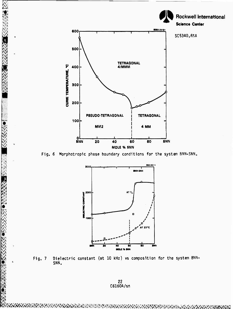
tially sharpened near Tc. The variation in the Curie point as a function of
composition is shown in Fig. 6, with the characteristic sharp drop in Tc occurring at the morphotropic (C.40)BNN-(0.60)SNN composition.
Figure 7 shows the dielectric properties as a function of composi-
tion. The major enhancement over the previously reported data is an 'ncrease
in the dielectric properties at Tc i'or BNN-rich compositions as a result of
improved ceramic sintering. The dielectric constant at the Curie point is
essentially flat on either side of the morphotropic boundary, with an abrupt
fpvtor of two jump in the dielectric constant at the MPB. The dielectric
properties at room temperature are generally monotonic with composition,
rising from a value of e = 100 for BNN to nearly 2000 for SNN. However, an
anomalously high value of c = 1200 occurred for x = 0.67; it is not presently
clear if this is a true local maximum near the morphotropic phase boundary or
if the SNN-rich compositions are still inadequately sintered. The steep rise
in the room temperature dielectric constant for x > 0,8 is due to the onset of
a second transition peak which occurs below room temperature. The influence
of this second transition can be seen in the dielectric properties for
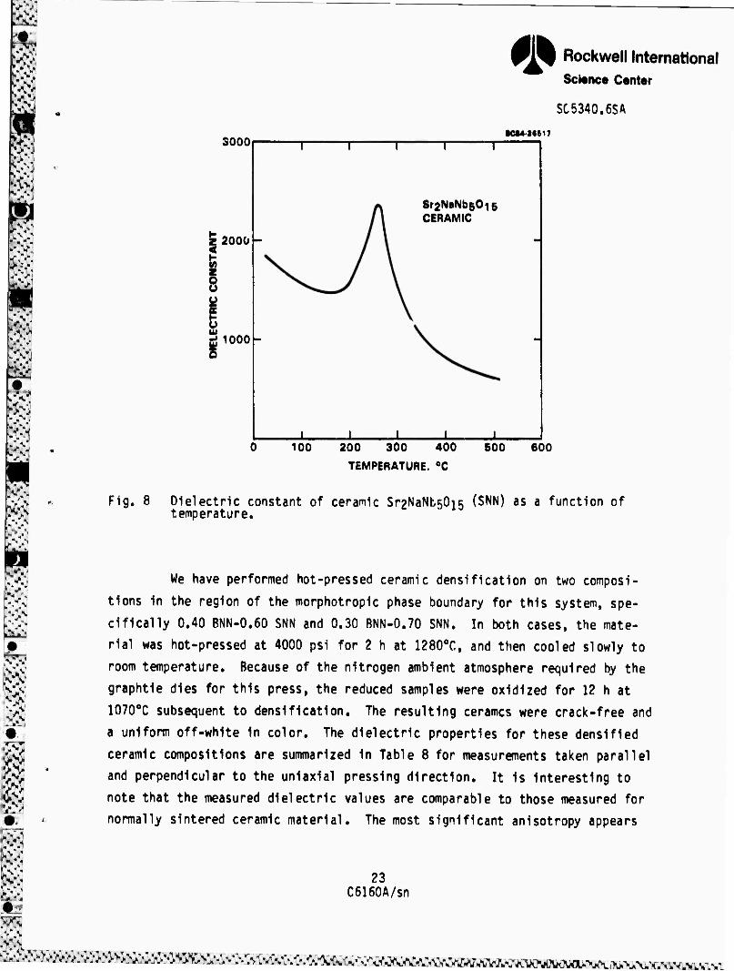
Sr2NaNb50i5 (SNN) shown in Fig. 8; preliminary low temperature measurements
show this to be a verv broad dielectric peak with a maximum near -50oC,
21 C6160A/sn
|
600
600
H 400
300
D 200
100
*
■cMimi
PSEUDO-TETRAGONAL | TETRAGONAL I
MM2 i 4 MM
X -L
Rockwell International Science Center
SC5340.fiSA
BNN 20 80 SNN 40 60
MOLE % SNN
Fig. 6 Morphotropic phase boundary conditions for the system BNN-SNN,
1000
•.".■
'.v '.V
W
2000
1000
•NN-BNN
Fig. 7 Dielectric constant (at 10 kHz) vs composition for the system BNN- SNN.
22 C6160A/sn
^^«^^^^^affl»&>^^.-:v;.:v>^»;^^^«agss^^b^i^^^w^^mg
'1* Rockwell International Science Center
SC5340.6SA
sooo •CM'26t17
Z 2000 <
ü
1000
Sr2NaNb601g CERAMIC
i JL 100 200 300 400
TEMPERATURE. 0C
500 600
Fig. 8 Dielectric constant of ceramic Sr2NaNb50i5 (SNN) as a function of temperature.
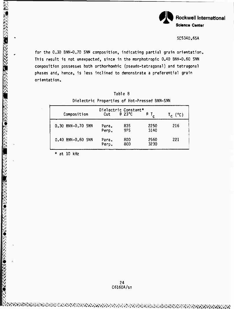
We have performed hot-pressed ceramic densification on two composi-
tions in the region of the morphotropic phase boundary for this system, spe-
cifically 0.40 BNN-0.60 SNN and 0.30 BNN-0.70 SNN. In both cases, the mate-
rial was hot-pressed at 4000 psi for 2 h at 1280oC, and then cooled slowly to
room temperature. Because of the nitrogen ambient atmosphere required by the
graphtie dies for this press, the reduced samples were oxidized for 12 h at
1070oC subsequent to densification. The resulting cerames were crack-free and
a uniform off-white In color. The dielectric properties for these densified
ceramic compositions are summarized in Table 8 for measurements taken parallel
and perpendicular to the uniaxial pressing direction. It Is Interesting to
note that the measured dielectric values are comparable to those measured for
normally sintered ceramic material. The most significant anisotropy appears
23 C6160A/sn
.svv ^■v:v^:v*v^^^
fl» Rockwell International Science Center
SC5340.6SA
for the 0.30 BNN-0.70 SNN composition, indicating partial grain orientation.
This result is not unexpected, since in the morphotropic 0.40 BNN-0.60 SNN
composition possesses both orthorhombic (pseudo-tetragonal) and tetragonal
phases and, hence, is less inclined to demonstrate a preferential grain
orientation.
Table 8
Dielectric Properties of Hot-Pressed BNN-SNN
Composition Dielect
Cut ric Constant*
1 230C PTc Tc TO
0.30 BNN-0.70 SNN
0.40 BNN-0.60 SNN
Para. Perp.
Para. Perp.
835 925
800 800
2250 3140
2560 3230
216 !
221
* at 10 kHz
m
24 C6160A/sn
^^^^^^^^^^^^^^^^^^^^^^^^»»^^«^»^^»^^^m^^f

* Rockwell International Science Center
SC5340.6SA
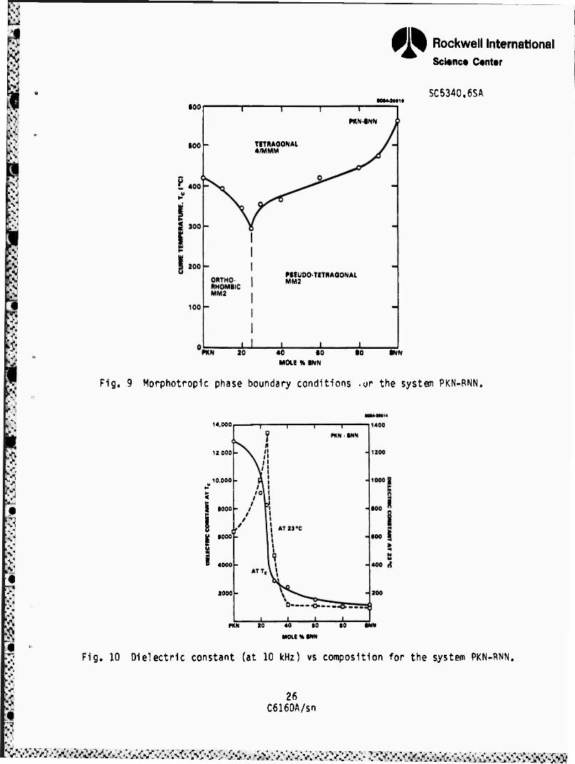
4,2 Pb2KNb50is-Ba2NaNb50i5 System
Another tungsten bronze of interest is PI^KNbsOis (PKN). This compo-
sition has been successfully grown in hot-pressed dense ceramic form by Nagata et al6 in Japan with a high electrochemical coupling constant, k^ = 0.40, and
good polarization. As such, it represents an attractive candidate for SAW,
piezoelectric and pyroelectric device applications. However, its relatively
high Curie point (470oC) makes it very difficult to completely pole. It is
also prone to cracking above 1200oC growth temperatures" and, hence, the
attainment of optically transparent hot-pressed material remains unlikely.
Because of the orthorhombic structure of PKN, the possibility pre-
sented itself of obtaining a morphotropic phase composition in combination
with pseudo tetragonal BNN. To this er.d, we began an investigation of the
pseudo binary bronze system (l-x)Pb2KNb50i5-(x)Ba2NaNb50i5 using cold-pressed
and sintered ceramic samples. A morphotropic phase boundary condition was,
indeed, found for the composition 0.75 PKN-0.25 BNN with a sharp minimum in Tc
of 270oC, However, cracking was a major problem in these ceramics, even after
lowering the sintering temperature for PKN-rich samples; hence, much of the
dielectric data were not viewed with confidence.
The addition of excess PbO, on the order of 1-3%, has been found to
dramatically improve the quality of ceramics prepared from this system with
the total disappearance of microcracks. Measured weight losses show the
ceramics to be approximately 1-2% Pb2+-deficient after sintering for 4 h.
Measurements of the Curie transition temperature as a function of composition
for (l-x)PKN-(x)BNN are shown in Fig. 9, and are only slightly different from
earlier data. However, measured values for the dielectric constant at Tc and at room temperature now show much steeper characteristics at the morphotropic
boundary, as can be seen in Fig. 10. The general dielectric behavior of the
near-morphotropic 80/20 composition and the two bronze end members, PKN and
BNN, are shown as a function of temperature in Fig. 11.
25 C6i60A/sn
8 I
fl» Rockwell International Sci«nce Cantor
eoo MM4MII
SC5340.6SA
-T
FKN-INN
TETBAGONAL 4/MMM
PSEUDO-TETRAGONAL
40 tO MOLE % INN
•NN
Fig. 9 Morphotropic phase boundary conditions .or the system PKN-PNN.
14.000
12,000
10.000
1000
•000
4000
2000
MN 20 40 »0
MOLt % INN
■0
Fig. 10 Dielectric constant (at 10 kHz) vs composition for the system PKN-RNN.
26 C6160A/sn
»^M'.vM^^^

•■^
V
14,000
• Rockwell International Science Center
•c(4-2«tis SC5340.6SA
100 200 300 400
TEMPERATURE, 0C
600 600
Fig. 11 Dielectric constant of ceramic PKN, 0.8 PKN-0.2 BNN and BNN as a function of temperature. Data for BNN is expanded by a factor of ID for clarity.
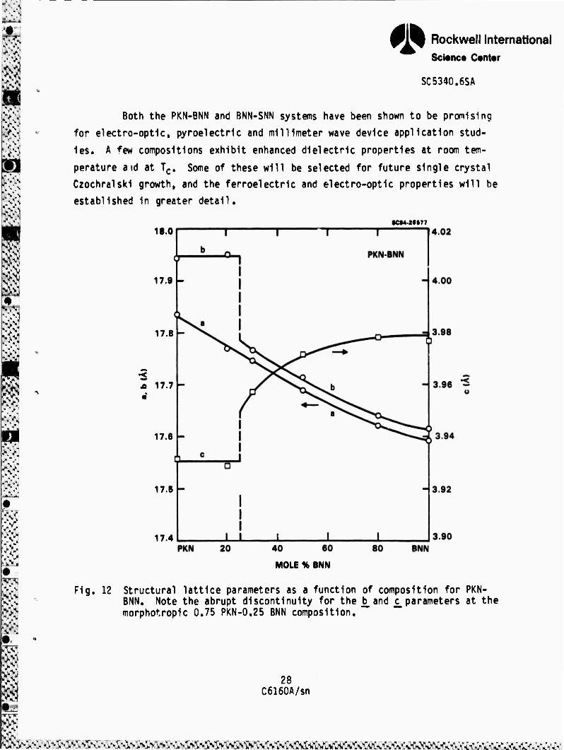
vd The dramatic changes in the dielectric properties at morphotropy are
reflected in the behavior of the lattice parameters as a function of composi-
tion, as shown in Fig, 12. These data were obtained by careful least-squares
evaluation of powder x-ray diffraction data, with excellent fits being ob-
tained for all compositions. Of particular interest in Fig. 12 is the smooth
monotonic decrease in the a_lattice parameter, whereas b_and c_remain constant
up to x = 0.25, at which point an abrupt discontinuity occurs. This dramatic
behavior suggests that near-morphotropic compositions in the PKN-BNN system
should display particularly enhanced piezoelectric and electro-optic
properties.
m 27
C6160A/sn
WKsaffl^M^i '^^^^^i^^^^^^MMma^^m^^^Bm
*» Rockwell International Science Center
SC5340.6SA
■V
Both the PKN-BNN and BNN-SNN systems have been shown to be promising
for electro-optic, pyroelectric and millimeter wave device application stud-
ies. A ^ew compositions exhibit enhanced dielectric properties at room tem-
perature aid at Tc. Some of these will be selected for future single crystal
Czochralski growth, and the ferroelectric and electro-optic properties will be
established in greater detail.
18.0
17.9 -
17.8 -
A 17.7 -
17.6 -
17.5 -
17.4
•«428877
Fig.
40 60
MOLE % BNN
12 Structural lattice parameters as a function of composition for PKN- BNN. Note the abrupt discontinuity for the b_and c_parameters at the morphotropic 0.75 PKN-0.25 BNN composition.
28 C6160A/sn
* - ;

• Rockwell International Science Center
SC534n.6SA
5.0 OPTICAL EVALUATION OF PBN
5.1 Introduction
The task taken up in the current contract period has been to comple-
ment the crystal growth work carried through last period and develop Pbl-xBaxNb206 (PBN) compositions close to morphotropy, but on the orthorhombic
side of the phase boundary.
In the family of orthorhombic ferroelectric bronzes in the Shuvalov
species 4/mmm (2)D2F mm2, the nonzero polarizations in the ferroelectric phase 2 2
are pi = P2 * ®* P3 = ^ an^ ^e ec1,jations ^or the spontaneous perturbation of the optical impermeability induced by the phase change at T become
AR11 = (hl + 92l)Pl
AR22 = (gn + g21)p5 (5.1)
2 ^33 = ^9l3Pl
AB12 = 966P1
For the single domain state, the optical indicatrix becomes biaxial
with three inequivalent principle indices. In Eq. (5.1), the nonzero AB^ is
due to the use of the original prototypic tetragonal axes. Rotating the axial
system 45° in the ab (12) plane eliminates AB12 and destroys the equivalence
between AB^ and AB^ in the new correct orthorhombic axial system.
Similarly to the tetragonal case, the morphic linear electro-optic r
coefficients are given by
?9 C6160A/sn
^^mmsm^^^m^^m^m^^^mi^^^^^^^^^a^m^^SM^^^^^^^^^^^

Ä
& Rockwell International Scl«nce Centei
SC5340.6SA
m = rzz ■ 2giiPieii
ri2 s ^1 ■ 2g?iPun
r13 = r23 a 2913^1633
r34 s ^35 = 2g44Pie33
r16 = r26 ■ 2g44Plell
In the ferroelectric phase, the dielectric stiffness xL is given by
(5.2)
33
'33 = 2a3 + \2Pl (5.3)
Because the longitudinal Curie temperature 63 is now close to ei in
compositions on the orthorhombic side but close to morphotropy, 03 will be negative and increasing with decreasing temperature. The transition at Tc is,
however, first order and thus Pi is less than parabolic against T, so that x33 will be small and decreasing with T. Thus, £33 will be large and increasing
with decreasing temperature, leading to large values of ri3, r34 and r35.
5.2 Exploratory Measurements
A number of PRN crystals have been pulled with compositions in- creasingly rich in Ra. For a morphotropic composition, ceramic studies
suggest that Tc «■ 260oC.
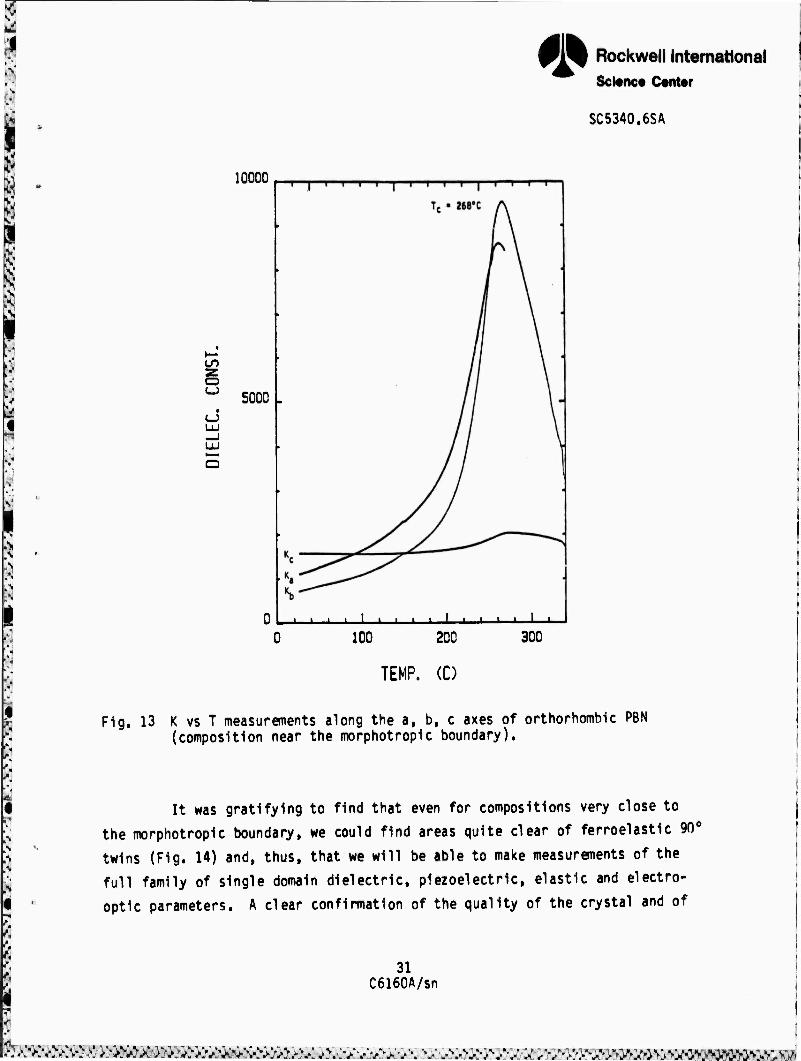
In Fig. 13, dielectric data are shown for a poled single crystal
region of a composition just in the orthorhombic stability region. It is
evident that the transition temperature Tc = 2680C is very close to the mor-
photropic value. The high value of Kc (the relative permittivity £33). is clearly evident, and the slow increase with decreasing temperature is also
evident. The rather small difference between Ka and Kb (en and e2?.) is un- expected and, if confirmed in future measurements, suggest an unusually small
value for 012»
30 C6160A/sn
£^v::- r.-:.-.y.y.y; *•.""<.'(•.'■• •'-**•"■>», O •/ O «^ ^t. '•c-r.L 00 jfZfi
!«w.v;.'
f» Rockwell International Science Canter
SC5340.6SA
10000
o
LJ
5000
i i i . L i i i i i
100 200 300
TEMP. (0
Fig. 13 K vs T measurements along the a, b, c axes of orthorhombic PBN (composition near the morphotropic boundary).
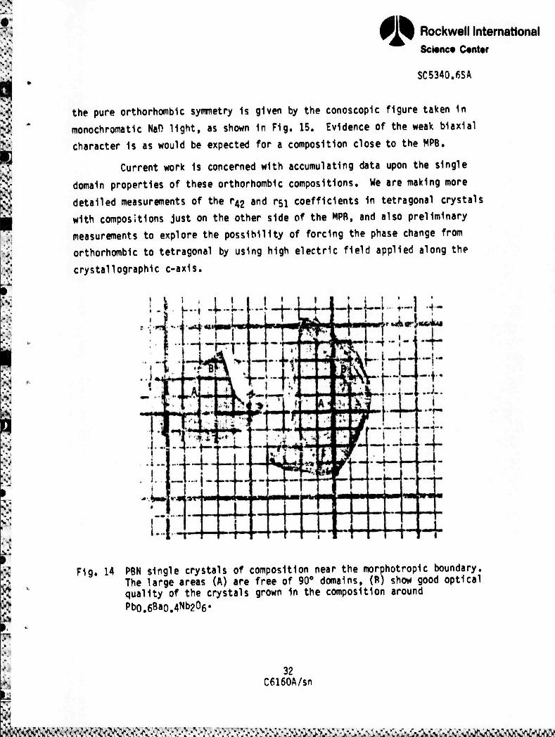
It was gratifying to find that even for compositions very close to
the morphotropic boundary, we could find areas quite clear of ferroelastic 9n(
twins (Fig. 14) and, thus, that we will be able to make measurements of the
full family of single domain dielectric, piezoelectric, elastic and electro-
optic parameters. A clear confirmation of the quality of the crystal and of
31 C6160A/sn
^.^^/v: ^v^: v^>:v^>^Xvcv^>^:v^;-^^^^. ^.KV\-AV^.! mmmmmmm^^ammBm
* Rockwell International Sconce Center
SC5340.6SA
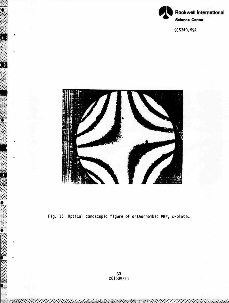
the pure orthorhombic symmetry Is given by the conoscopic figure taken in
monochromatic NaH light, as shown in Fig. 15. Evidence of the weak biaxial
character is as would be expected for a composition close to the MPB.
Current work is concerned with accumulating data upon the single
domain properties of these orthorhombic compositions. We are making more
detailed measurements of the r^ and r5i coefficients in tetragonal crystals
with compositions just on the other side of the MPB, and also preliminary
measurements to explore the possibility of forcing the phase change from
orthorhombic to tetragonal by using high electric field applied along the
crystallographlc c-axis.
Fig. 14 PBN single crystals of composition near the morphotropic boundary. The large areas (A) are free of 90° domains, (R) show good optical quality of the crystals grown in the composition around Pbo.6Ba0.4Nb206'
32 C6160A/sn
^m^ttK^^^te^^
€> Rockwell International Science Center
SC5340.6SA
Fig. 15 Optical conoscopic figure of orthorhombic PBN, c-plate.
33 C6160A/sn
^ätitätä^

«» Rockwell International Sci«nce Center
SC5340.6SA
6.0 EVALUATION OF THE PHOTOREFRACTIVE EFFECT IN DOPED AND UNDOPED SBN:60
6.1 Introduction
The effectiveness of undoped SBN:60, SBN-Fe3+ (1% by wt.) and
SBN-Ce3+ (0.1% by wt.) as photorefractive media is studied here using the
method of two-beam coupling. In particular, the absorption coefficient, the
two-beam coupling coefficient, and the writing sensitivity of each crystal is
determined, and then used to compare the materials with one another.
Consider the two-wave mixing experiment shown in Fig. 16, Beams 1
and 2 are plane waves which intersect in the crystal and thus form an inten-
sity Interference pattern. Charge is excited by this periodic intensity dis-
tribution into the conduction band, where it migrates under the influence of
2«d 2 = 0
Fig. 16 Experimental setup for two-heam coupling experiments.
34 C6160A/sn
täsüü&zmiifZ^^

.V
0» Reckwell International icience Center
SC5340.6SA
diffusion and drift in the internal electric field, and then preferentially
recombines with traps in regions of low irradiance. A periodic space-charge
is thus created which modulates the rt.ractive index via the electro-optic
effect. This index grating, being out of phase with the intensity distribu-
t introduces an asymmetry that allows one beam to be amplified by con-
st* -ive interference with light scattered by the grating, while the other
beam is attenuated by destructive interference with diffracted light.
Mathematically, this two-beam coupling may be described in the
steady-statp as follows:
dU UU BT " Y ^ + I2 " aI2 lb,u
where Ij and I? are the intensities of beams 1 and 2 inside the crystal, y is the two-beam coupling coefficient, a is the absorption coefficient, and E, =
z/cose^, where 0 < ^ < A = d/cosei. The transient behavior is modeled by
li^'.t) = (l-e-t/^j^jt * ») + e-t/T^^-t = o), i - 1,2 (6.2)
where c is the characteristic time constant and ^(^t ■>■«') = Ii(c).
The solutions of the above coupled wave equations are
Mi) LT^O) + I2(0)] e^
1 T[me
[^(0) + l2(0)] e"01
TJTöT TTOrr
12(11' iTTC». 36
C6160A/sn
g-^jtojO->>M-si1,^>S,i>^^,^->> «i ^^S^^s^^S^n^!^^^

* Rockwell International Science Center
SC5340.6SA
Maximum coupling will, therefore, result in crystals with large y. hut small
a. However, a and y are not independent. In fact, since charge must first be
excited into a conduction band by the intensity interference pattern in order
to start the photorefractive process, some absorption is necessary. This is
precisely where the role of the dopant enters, Hy purposely introducing im-
purities into the crystal, donor sites are created which become the absorption
centers. It must be noted, however, that any absorption which does not con-
tribute to the photorefractive mechanism is undesirable.
6.2 Photorefractive Measurements
Figures 17 and 18 show qualitatively the effect of Ce and Fe impuri-
ties on the absorption spectra of undoped SBN:60, whose spectra is given in
Fig. 19. Several interesting observations can be made. For one, the band
edge shifts from 400 nm in SBN to 430 rm in SBN-Ce and 500 nm in SBN-Fe.
Secondly, although the SBN in Fig. 19 was not intentionally doped, there are
signs of deep level impurities evidenced by perturbations in the spectra near
550 nm. Finally, the effects of Ce and Fe in SBN are seen to be significantly
different. While the spectra of SBN-Ce is rather featureless with a broad
deep level centered at 480 nm, the spectra of SBN-Fe displays a structured but
otherwise broad absorption extending from 500 nm to 700 nm, with characteris-
tic peaks at 500 nm and 590 nm. Future investigation of these lines will
indicate whether or not they contribute to the photorefractive effect.
The final quantity of interest, the writing sensitivity W, defined by
W = [li(0) + l2(0)]t» is a measure of the incident energy needed to produce
the index grating. Since, in basic photorefractive theory, W is a constant,
the writing sensitivity also serves, therefore, as an indicator of the speed
of response of the crystal for arbitrary values of irradiance.
36 C6160A/sn
> -

*» Rockwell International Science Center
SC5340.6SA
nnT ._— rr- "^T 1 :' —r ■~T ' 1! TfT T■" T" [' ' 17 ' j 1 TTT ̂ T— II
^§
i i ii ;:i '^l1 Hü ;,i' 1 ' i ; 1
1 1I1 1' ,'l 1 ! :i!s ! S ' ' !ii 1 s m ■'5 1 1 ■ •
i # ! S ■ ;l ii I ! 'ii5 iS m Mi |i! 11 ] ;I|! ,,1' 11 i l 1 :- :i 1 i 1 ■pi lii iHi 1 ii : 1 i jlll 1 W M .!i! !li liii , ! ; 1 llj •M! ''1 J'H j ;i 1 Uli ll li
■;!i ;!li 1 111 im m
wr 'i'li ml . 1 1 I 1! : Ij i'! 1 il ( 1 nlj 1 !| Ihl 1 l t; hli i||| I i 1 tt ! l! P ;■ 1 ; 111 1;. ' 1 . 11 i 1' ■\\\
i lii [l.i ■ t ; 1 1 ; ' 1 1 i 11
1 l' i*i lii'j 111 ilTt ■, i
:"', , i'l' n-fJ
IM 1 M |i|! '.!! iiij 11 i 1 ■ iji
L' ill' rf'jj ! !' 1 j 1 1 1 i " h{ 1 il Mil jlji üi 1 !| !'; ; 1 ,
i'l' 11 •"•f m
0
1 j
1 1 . 1 1 : 1 Ii 1 |l 11: i ^ ll i > t i '.'ii !ii . ,
1 , ! ini it!]
' 1 ! ' ' I i . . i ii ! 1 \ i ' IM! i. • , ■ 1 ■ ; 1 ■ ll ! 1 , lii: |J ; ! 1
' ' 1 1 ' j j ;hi 1 ! ;! i ■
1; 1 11 ■ ■ 1 1 ■' 1 ■ t i < ; 1 1 1 . ' • ',
. ; l| 1 ' i . ' 1 . .
.,!■ ;i| i u; 1
r 1 j ill 1 1 1 i ' ! 1 1 1
!| . :i 1 'i '' 1 »c
1 1
/ • er
■ i i j
' i : M l t i ■ - - i ■ ■ , • t ■■ 1
1 j ■ 1 ' 1. i
00
7C
X
(nm
)
ft 1
c ! , 1 i J
9 f 6
• e ' e r5 ö
m e
1 ** f ° e
e e
' i ' 1 /] z co
1 1 \ 1 ! ;i 1 :' 1 . j: 1 V4-
O ) 1 1
t 1
■ / j Im
■ , ; i , ■ 1 1 i 1 i / 1 , 1 ', . 1 O
1 h ll / D. 1 f
O
,1 i 1 J 1 C O
1 " 1 / 1 i 1 i / 1
Q.
i 1 1 1 / i 1 O
1
1 1 ! ,1
1 l 1 j/ ! 1 1 1 ji 1 / 1 1
1 1 1 ' t, , 1 i 1 j\ i,:; 1—1
i 1 ' ' 1 ■ill : 1 i
. j \ l!li • 1' i ii 1 .
' • ; f j , liii ! 1 CD
! s; • • e . K
','«* s ■: 1 1 1 •
i # / 1 t
e ■ Z e e m Ü.
ji I'l, ■' I' ,
f ' litt 1, 1 l"1
' ' 1
! . ■' 1 1 | ; :!', M1; 1' (■ ;il M l ' ' ,, i , ;', : 1
' i ■ 1
ill 111 ;;', i 1 H ' 11: 1:, i ■ 1
1 ' ■ 1 j 1!! 'lii i ii' Mli i:l; 1 1 ijl] ; : ! i : 'lii l . : 1 i'
■\'\
1 pi hl1 1 liii
' ' : 1 •i'l 1 ' 1 .< 1 r 1 Im M1 i ' i! ! "■; ill1 ■ 1 : ! . 1 i,; 1 • !' IM
1 1 ■ I'' !;' , 1 ' i t! i 1 1 1 , lj| Ml1 Ml: il'' lii'j ilü !ii! i i •
t' t ■ 1 li1 '■; . ■. • 'Ü 17 ■Hl l|i ::;i iiij 1 ■
'llj 1, j
'V ||l
m 1 7 i 1 ■! l,li 1 ! : : IM" i , • , 1 j . l|il :|i| 1 . ;ll i ;; ■ 'hi 1 1 i ' 1, I'l'' ,;;! hi. ':> *i 'Ii' Mil 1 1 j 1 IIP I'll ,,.} |(|] im
V' ■■'•
1 1 1 y W'-' "'il
1 r ' '
' 1 > j.j. j I . Üi 1 ! 1 ["ii i'l1
■' 1 : i ,1 W\ •'ii il :i'l illj N Uli llli il 1 ^i ilil •»
—«— i - "M ;; lljl 1 : ! ■m II! ll 1 i(j
- ■ Mt ■"I. ii 1 1 :, i; jii al ; 1 \__i , i 1;
Mim ^tr ilil ük Ml
jj
(sa-pun KaFa^iqiB) o
37
^^^^^^^^s^^m^^^ü^^^m^^^^^^^m.jmkz-^&tmmm^^^^m

*» Rockwell International Science Center
SC5340.6SA
JS =3 . 1 ; 1 ! ! > — ;,; ^ • II!| fü tillu w MH
i t^ 111 i Mil Ijl ! 11 L{ j ' ■ ' 1
; i, iii ll1 ll!| iii jpm;; ■ ]! lii l!l 111
illl .;: i i
1: 1 l "ll lli !i:| Hl l\i i ! i
1 Mi 1 ii!1 ■
i. i i lij 1 , j 111 H: rl'1 1 i ■
111 i1! i - i ■ 1 !, iü lil I' 111 il! ii'
Linl lt:
id ;,i II] I 1 1
II HI in ll hi Jm *I6P
\\ j i j !|i \ i' L ' j 1 : j i Ih 1 l !ii I''
; 11 ■ 1 | l!!j III 11 ;l1 \ |i Hl ii; ! ■ i 1 ; 11 i ■!;! 111 1|| ii! tii iii 111 IM 'ii l| n1
\ ; 1 i
11'! !■ ' ', M li! ! t M !|| ! 1*1 1 l'1
m|! ;iii 111 11 ' i > iiii iii 11! Iii ill Ih l'i |:, Mi ! > ill \ ;: i
!h " • 11 11; ■ '. ii' M i'1 i; i ; [' ;i ilj 1: i l.l| iii 11 nin
■ l; : ! I1, ii ; i 1 11
■ Ih . 1' 1' i '1| jÜ 1
i' ::' II i i 1 , j
i ■ ■ ' j i : !lil i • / | : 1 1 I'1 'l1' ■ | ti'i /
| ■ ih i i '
' 11 i , i '\ ill im. /
1 ' 5 6 m '11 IB ' e
1 6 , , ■ ■2
, i ■is |i laly e J TW
i' ii; ' 11 111 11' ; , , |,' ' 1 1 1 . , ii ,11 ■ it/ l*%
1 1 ) ■ 'ji 11!
'' ■ 1 :!
i1 ■ ' ■ *! h; ■ ■ 1 i i ■ : j : in ill :' |i| !:i| ■ v- , ! 1 ■ 1 i ; ; I ,i : j i M > ; .. 1111' "A' '
■ '•', i ■ i ■ ,1 ; .j ii n i ^ b%A
■ 1; ■
i1! i ' ' : 1 III Hl Iv SJU
| ;i ii ■ j . 1 ; ; ' 1 '
.;. '■-- ' 1 ■! i iiii M ii f 'i ■, ■
! •■ i 1; 1 ' i :'' 1 1 ■ i j , ;. 1 l|: hi i
III il, l1' 1 11 ! ' 1 ;
! ■ , ■ Ml ;/ ' 1! 1 h
■
! ' ■ [\ ^r* ;i ! ■1 ■ i I'll ; \XJT
1 . ■ 1 j
' i Ml
1 i ' ^ : ! 1 ■ 1 , , i i i | ;': i 1 1
i ■ i 'll , 1 ! ■i'l hfil
t ■ i llml i.
-w W
1 ■ l" V i i 1 e 1 5 e ' Ö jiS o 2 SI e
e i
, i I I ' | ;
il i ,
■ ■ j iii l i ] ■ | j | i"! ;i! ■ , •> ÜÜ !•
VI ^
|- ' ' ( hi i'lj 1! ':1'' Hl i i ' ijj :ii! llj! iJlj ijiii\ II III: ■ ■ i 1 > i ' 1 ! ; : ■ i ■ hl1 Mi!
;!': 'i' -r i Illl'. -1
' ' 1 ' i ]' 1 1 . !!tl ■' ill1 Hl * ' : 1 1 ! ; ilii' i
üii H1! Ijii lli n| tiijki 11
;ii 'ii1 11
iii ' t ■ i ! t t i iii
! i; i iili Mi in iij 'iji
: ' ; 1 :11 jimn. 111 liiil-i • i ' j ■: !|! 11 1 t ' i . i i Ihl ■in i ii 'in
..:\ "ii miliin i lil|i!!l Jai &k ! lil llj] M i^i i
Tti i 1 ■ i i i 1 { :l| 1 • *'! Iii! ''V\J iHiii 'iii 'in 1 . ijl; ! ■ ! Uli
1 [j ilj ■ * i: , ; j ii]; i,!
i' i. iiii !li! üF i , i,'
ilili' ' ; 111
[1 ill ; ; :'! I ■lit !i:' .ji ■ll: Ur] iii! ■ Ii ;i ' "111
,'■ i!1! i i i 1 . ; ;l| ;: : ; ;; 1 1 ■ i ■ ■ X ■ ii L,, ■ li ji III
,,' : ■ ■ i i ' ]
i!' i UM i"'' * ! 1 Illl ^0 'T' ! ||'||j ,1'i ' ,u,m irtiif 1 i ",' . 11 1 ' ' ■ _ -— 11 ■ "; 1 'll' lllilll p"
f ^1 i ' i .ii piliii: iii '; ■ i i H'i Jlll - 11 l1'! ■'.
,'1 . 1 ! 1:11 11 NhÜ III! ■ih i[ii ; , ■! ,: 1! 1 'Mi
:' ■
: i i 1 ■ 1
'■-II
/ .ii. iii ill k ' ' i J ii 1
ÜÜ 1!' 1!!' i * ■ 11.: i i •: j —^. v|liil jiihil" ;,!■
o as
e c
o o m
(saTun XaBa^fqae) o
38
c
i c;
V.
(. 4-> U a- Q.
c o
Q. I. o
o>
L So ^^^^^sä^x^^s^üw^&ix^^^M^^^^^mfzmmi&iiM.tzmKmirms^mms,

<» Rockwell International Science Center SC5340.6SA
ll: """" ' ""^ ■"" m^t ^^ m^ ■~* ^^ —i '• " ^1 [j'l 1 !
, g
1 1 ■ ] _ 'üj :!i
■
IM' nil ' , ' i nj 1 1 , j ■ 1, .i'i 1 0
1 1 : tM HI 111 i i ' i
\\! ij,: l! '1 l!|i II ' -, >' i, ii,! !|
'! lli m 1, ii !l i ■j i j I ; , t 1 ilii iii :; : iii* iii |l 1 ii r
1 * i . 'il ;, i t ■
■ ii! . : " ! i'ii ill I II i m' '•':'. 177! ii|i ' i ' fi1! ij;! ;;:, i1'
: i! ■ ■ i
" ÜM '■'■ i'i . n i. ; 11! ] :ii| l;:i 111 |i| , , ■ ! 'ii' 'Mil l|| ftl 11 • ;' ; INI ,11.
i' ■ '.i iM| 'l'i il '• ilii -j ■ 1 1 : ::' "' 1 i ^10
■' ■ i ,,:!,:.' i ■ t IM i i :ii; Ilii Ilii | # | im ■ j 1 I iil hi |ll i i 00
{ c 1 ö !'2 e S w
'iif ; I .IS : 1 ;5 h 1 ! i' 1 [
■:l
i ■■ j •
il ■
111 i' . i *, ; j
1 i; | '
™,
■ I i , h |; ■ [ij i IM :; I i ^ ■1 : : ■ • . ' i ,.:' im ,, j '
, ! 'ill 1 ' i 1 1 1
! 1
- i 1 ' ijll
in; .iii ii1 1 ' 1 in Ii i' i, 11' lii [.; ' 1 '• i ' ! 1 'Il i ] I, ■■. | | 'iii 11', in i'i > j O
1 ■ i ' llJl ' i j
"S1
1 ■ •! ' : iiii
; , , | i/ i^.
I'I . ■ ! ■, i ''^ i h, ;!" :; i'ii I o
i 1 1 • i! ' ' ' 1 ' , ■ ■ * t
l 1 IT
: i > ; I r'iü ■■: | ;
' , ii!. ' 11.: ■ i ' ii c
o =1—
1.
e s S ■ ■ * • ö
« e 5 . ! i e
1 e ■ 1
1 . : ' t ■ j i o
L o
' II * i ■ ; i ! ■ i ■ ' '1 I
t
i i 'I : ,''■ ' ' ; 1 '1 : | o-
1 1 ; ■ i • ■il 1 , t 1,1; i
ijj '<<: '.. i' 1 ^ L | Oi
1 , t t > 111 TTT*"
| . ■ I i . ■ •i: u. i]! i i hi ■ 1 '
1 ' I j j IM i!!' i i Jill
Uli ill ill I1 IM ; ' j
. !; , i!; nr1* jlji jjl jjl: '' i! ij 1 i! ' .i' ijij i ii ii:i
\:'\ | 1 1 1 Hl ilii i 111
i'i i'i' i'ii i iii < i! I'i I'll r o m
o
■ ! ; ■ - iiji |l!| ; 111 14 • iil
II | { I'll i, 11 .ill Im i i 11
I'I! I"1 , ' Mil
i 1 lllil'i i'l '
::i' 1t in; 111 ' i i 1 iijl llj !!i Mil ji] i ' t
'1 1 i!' 1 ' \'\ 'i '■■ 1 1 r'l
■ i t : - ri;i iii ' 1 i 1 '' : i n ( i)»i
ill1 i'i1 iii; \]'\ 1 I1 :ii! ill i il Ii' hi' '' 1; i, t;'' lljl fm ' i ; | >': 1 ml •Ah [ 1 ' ' l'i' il!1
i'ii 'Hi mm' ' ■ ' ii: ■' i ; j:; ;■,!
1) ; 1 ' !|l m i i i' ;[t| 1 , Uli ;i|! H1! III j'j iijiiii h' ■ | '•
' ' 1 nii I;; ■' 1
■ i • t i I 1 ' I . i i 'Iil ,!:i 1 ' 1
. 1 j ■ Jlr-f iii i i, .11' i'.i
\ ■ 5 t e ': i iii s ' e iH 'III L1 ill' i'S II mi lihl ' i'
1 : ■ : i i : i;!l iii i i' i 'ill IM '. i i i l'.il ;;l Hi' 'lij ;,;, lip 'Iii 'II1 I 1 ! lli' H '|!! ;' ', ::!l i . 'r i iii ■
• 1 ' 1 ■ , 1 * 11 ''ii i hr 1 li:i rl' 1 i
iih 111 ' 1 r l\U iir ij.l ||i jjii iitl !lil Uli ■ i j .
till III H\ i |ii| || F1 O
; 1 ! :':! rni rrr 'Ml ■rftr — "TT
-^-r ü i' 11 i
!ii iii 11II1 i 1
II Hi' mtm
ll
■■' : [[Ml Ulk . h ' "^iT ;; >■
i 1
zu £1 yin Ijj ; 'II! m : ,| Ml LliLili !:|ll. ±
7-- 39
Vza&m&fiA/^^^

* Rockwell International Science Center
SC5340.6SA
Table 9 summarizes the experimental results for the three materials.
Unfortunately, the SRN:60-Fe crystal was excessively doped, which created
striations that interfered with measurements of y and a. Therefore, only the
writing sensitivity was obtained, anJ was found to be about ?.$% larger than
that of undoped SBN. However, this result should not be used to conclude that
doping SBN with Fe results in a slower photorefractive materials, since the
quality of the particular SBN-Fe crystal was lower than that of the other two
crystals. A crystal with lower Fe content will probably render much better
results.
The data in Table 9 indicate that the introduction of Ce into SBN:60
results in a crystal with a larger two-beam coupling coefficient and a better
writing sensitivity. However, the absorption coefficient is affected nega-
tively. This increase in absorption may, indeed, be unavoidable, since it
probably contributes to the better values of y and W. Also, future experimen-
tation with the reduction ratio of SBN-Ce, i.e., the fraction of Ce3+ to Ce4+
in the crystal, may further increase the effectiveness of SBN-Ce as a photore-
fractive material.
Table 9
Optical Properties of Doped and Undoped SRN:60 Crystals*
SBN SBN:Ce SBN:Fe 1
o(cm-1) 0.04 1.8 !
j yCcm-1) 3.0 11.0 1 W(mJ/cm2) 122.0 101.0 152.0
* Experimental results for 2e0 = 15°, \ = 5145Ä, ll(0) + I2(0) = 100 mW/cm?, l2(0)/Ii(0) = 2
40 C6160A/sn
^S^^<^^^^^ •.W'

s a &
•
0» Rockwell International Science Center
SC5340.6SA
7.0 FUTURE PLANNED WORK
• Further refine and evaluate the growth of high purity single
crystal SBN:60.
• Establish optimum concentrations of Fe and Ce dopants in SBN:60
necessary for improved photorefractive sensitivity and speed.
• Examine the dielectric and optical properties of SRN crystals
doped with other cations.
Establish SBN:75 LPE growth from the SrO-BaO-Nb^Os-VpOs flux
system.
Continue development of the BaV^Oß-PBNreO and Pbi.xBaxV206-PBN:60
flux system for LPE growth.
• Attempt single crystal growth of near-morphotropic BNN-SNN and
PKN-BNN bronze compositions for dielectric, structural and
optical evaluation.
• Continue measurement of the E-0 coefficients of near-morphotropic
single crystal PBN.
41 C6160A/sn
AV!': ^V^^VrVv^^^^
* Rockwell International Science Center
SC534n.6SA
8.0 PUBLICATIONS AND PRESENTATIONS
8.1 Publications
1. R.R. Neurgaonkar, W.K, Cory and J.R. Oliver, "Growth and Applications of Ferroelectric Tungsten Bronze Family Crystals," Ferroelectrics St, 3 (1983).
2. R.R. Neurgaonkar, J.R. Oliver and L.E. Cross, "Ferroelectric Properties of Tetragonal Tungsten Bronze Single Crystals," Ferroelectrics ^6_, 31 (1984).
3. T.R. Shrout, L.E. Cross and D.A. Hukin, "Ferroelectric Properties of Tungsten Bronze Lead Barium Niobate (PBN) Single Crystals," to be published in Ferroelectrics.
8.2 Presentations
1. R.R. Neurgaonkar, W.K. Cory and J.R. Oliver, "Growth and Applications of Tungsten Bronze Family Crystals," presented at the 1983 IEEE Int. Symp. on Applications of Ferroelectrics, June 1-3, 1983, Gaithersburg, MD.
2. R.R. Neurgaonkar, J.R. Oliver and L.E. Cross, "Growth and Application of Ferroelectric Tungsten Bronze Family Crystals," presented at the 5th European Meeting on Ferroelectrics, Sept. 26-30, 1983, Renalmadena, Spain.
3. T.R. Shrout, H.C. Chen and L.E. Cross, "Oielectric and Piezoelectric Properties of Tungsten Bronze Lead Barium Niobate (Pbi-xBayV^Os) Single Crystals," presented at the 5th European Meeting on Ferroelectrics, Sept. 26-30, 1983, Benalmadena, Spain.
4. J.R, Oliver and R.R. Neurgaonkar, "Ferroelectric Solid Solutions Based on the Tungsten Bronze Structure," presented at the 86th Annual Meeting of the Am. Ceram. Soc, April 30-18, 1984, Pittsburgh, PA (invited paper).
5. J.R. Oliver and R.R. Neurgaonkar, "Morphotropic Tungsten Bronze Solid Solutions," accepted for presentation at the 37th Pacific Coast Regional Meeting of the Am. Ceram. Soc, October 28-31, 1984, San Francisco, CA.
6. R.R. Neurgaonkar, W.K. Cory and J.R. Oliver, "Ferroelectric Tetragonal Tungsten Bronze Crystals for Optoelectronic Applications," accepted for presentation at the 37th Pacific Coast Regional Meeting of the Am. Ceram. Soc, October 28-31, 1984, San Francisco, CA.
42 C6160A/sn
^^j^ätiäm^m^y^t^^
* Rockwell International
Science Center
SC5340.6SA
I » 9.0 REFERENCES
1. U.V. Voronov, I.R. Dorosh, Y.S. Kusiminov and N.V. Tkachenko, Sov. J. Quantum Electronics J10, 1346 (1980).
2. K. Megumi, H. Kozuka, M. Kobayashi and Y. Furuhata, Appl. Phys. Lett. 30, 631 (1977).
3. J.E. Geusic, A.J. Levenstein, J.J. Rubin, S. Singh and L.G. Van Uitert, Appl. Phys. Lett. _U, 269 (1967).
4. R.L. Barus, J. Appl. Cryst. J_, 290 (1968).
5. R.R. Neurgaonkar and L.E. Cross, Final Report (DARPA), Contract No. F49620-78-C-0093 (1982).
6. K. Nagata, T. Yamazaki and K. Okazaki, Proc. 2nd Int. Meeting on Ferroelectric Materials and Thoir Applications, 251 (1979).
43 C6160A/sn
>c<i2^öfß«^y^^"^^^^^vww:^wwN