Embed Size (px)
Citation preview
Of the National Institute of Building Sciences
ProgramonImprovedSeismicSafetyProvisions
2000 Edition
NEHRP RECOMMENDED PROVISIONSFOR SEISMIC REGULATIONSFOR NEW BUILDINGSAND OTHER STRUCTURES
Part 1: Provisions (FEMA 368)

The Building Seismic Safety Council (BSSC) was established in 1979 under the auspices of the Na-tional Institute of Building Sciences as an entirely new type of instrument for dealing with the complexregulatory, technical, social, and economic issues involved in developing and promulgating buildingearthquake hazard mitigation regulatory provisions that are national in scope. By bringing together inthe BSSC all of the needed expertise and all relevant public and private interests, it was believed thatissues related to the seismic safety of the built environment could be resolved and jurisdictional prob-lems overcome through authoritative guidance and assistance backed by a broad consensus.
The BSSC is an independent, voluntary membership body representing a wide variety of buildingcommunity interests. Its fundamental purpose is to enhance public safety by providing a national for-um that fosters improved seismic safety provisions for use by the building community in the planning,design, construction, regulation, and utilization of buildings.
To fulfill its purpose, the BSSC: (1) promotes the development of seismic safety provisions suitablefor use throughout the United States; (2) recommends, encourages, and promotes the adoption ofappropriate seismic safety provisions in voluntary standards and model codes; (3) assesses progress inthe implementation of such provisions by federal, state, and local regulatory and construction agencies;(4) identifies opportunities for improving seismic safety regulations and practices and encouragespublic and private organizations to effect such improvements; (5) promotes the development oftraining and educational courses and materials for use by design professionals, builders, building reg-ulatory officials, elected officials, industry representatives, other members of the building community,and the public; (6) advises government bodies on their programs of research, development, and im-plementation; and (7) periodically reviews and evaluates research findings, practices, and experienceand makes recommendations for incorporation into seismic design practices.
See the back of the Commentary volume for a full description of BSSC activities.
BOARD OF DIRECTION: 2000
Chairman William W. Stewart, Stewart-Schaberg Architects, Clayton, Missouri
Vice Chairman Charles Thornton, Ph.D., PE, The Thornton P Tomasetti Group, Inc., New York, NewYork (representing the Applied Technology Council)
Secretary Jack Prosek, PE, Turner Construction Company, San Francisco, California (representingthe Associated General Contractors of America)
Ex-Officio Eugene Zeller, PE, City of Long Beach, California
Members J. Gregg Borchelt, PE, Brick Institute of America, Reston, Virginia; Charles Carter, PE,American Institute of Steel Construction, Chicago, Illinois; Bradford K. Douglas, PE,American Forest and Paper Association, Washington, D.C.; S. K. Ghosh, Ph.D., S. K.Ghosh Associates, Inc., Northbrook, Illinois (representing the Portland Cement Associa-tion); Gerald H. Jones, PE, Kansas City, Missouri (representing the National Institute ofBuilding Sciences); Do Y. Kim, PE, Institute for Business and Home Safety, Tampa,Florida (through October 2000); H. S. Lew, Ph.D., PE, National Institute of Standards andTechnology, Gaithersburg, Maryland (representing the Interagency Committee for SeismicSafety in Construction); Joseph Nicoletti, PE, URS/John A. Blume and Associates, SanFrancisco, California (representing the Earthquake Engineering Research Institute); W. LeeShoemaker, Ph.D., Metal Building Manufacturers Association, Cleveland, Ohio; HowardSimpson, Sc.D., P.E., Simpson, Gumpertz and Heger, Arlington, Massachusetts (represent-ing the National Council of Structural Engineers Associations); Charles Spitz, NCARB,AIA, CSI, Architect/Planner Code Consultant, Wall, New Jersey (representing theAmerican Institute of Architects); John C. Theiss, PE, Theiss Engineers, Inc., St. Louis,Missouri (representing the American Society of Civil Engineers); David Wismer, PE,CBO, Department of Licenses and Inspections, Philadelphia, Pennsylvania (representingthe Building Officials and Code Administrators International)
BSSC Staff Claret M. Heider, Acting Executive Director; Bernard Murphy, PE, Director, SpecialProjects; Patricia Blasi, Administrative Assistant; Carita Tanner, Administrative Assistant;Kelly Harris, Summer Intern
BSSC Program on Improved Seismic Safety Provisions
NEHRP RECOMMENDED PROVISIONS(National Earthquake Hazards Reduction Program)
FOR SEISMIC REGULATIONS
FOR NEW BUILDINGS AND
OTHER STRUCTURES
2000 EDITION
Part 1: PROVISIONS(FEMA 368)
Prepared by theBuilding Seismic Safety Council
for theFederal Emergency Management Agency
BUILDING SEISMIC SAFETY COUNCILWashington, D.C.
2001
ii
This report was prepared under Contract EMW-97-CO-0481 between theFederal Emergency Management Agency and the National Institute of BuildingSciences.
Building Seismic Safety Council activities and products are described at the endof this report. For further information, contact the Building Seismic SafetyCouncil, 1090 Vermont, Avenue, N.W., Suite 700, Washington, D.C. 20005;phone 202-289-7800; fax 202-289-1092; e-mail [email protected].
Copies of this report may be obtained by contacting the FEMA PublicationDistribution Facility at 1-800-480-2520.
The National Institute of Building Sciences and its Building Seismic SafetyCouncil caution users of these Provisions documents to be alert to patent andcopyright concerns especially when applying prescriptive requirements.
NOTICE: Any opinions, findings, conclusions, or recommendations expressed in this publication donot necessarily reflect the views of the Federal Emergency Management Agency. Additionally, neitherFEMA nor any of its employees make any warranty, expressed or implied, nor assume any legalliability or responsibility for the accuracy, completeness, or usefulness of any information, product, orprocess included in this publication.
iii
PREFACE
One of the primary goals of the Federal Emergency Management Agency (FEMA) and theNational Earthquake Hazards Reduction Program (NEHRP) is to encourage design and buildingpractices that address the earthquake hazard and minimize the resulting damage. Publication ofthe 2000 NEHRP Recommended Provisions for Seismic Regulation of New Buildings and OtherStructures reaffirms the continuing FEMA-sponsored effort to improve the seismic safety of newstructures in this country. Its publication marks the fifth in a planned updating of both theProvisions documents and several complementary publications. As in the case of the earliereditions of the Provisions (1985, 1988, 1991, 1994, and 1997), FEMA is proud to sponsor thisBuilding Seismic Safety Council project and encourages widespread dissemination and voluntaryuse of this state-of-the-art consensus resource document.
In contrast with the 1997 Provisions update, this update does not make significant changes to thehazard maps or design procedures. Rather, the 2000 Provisions contains new material in selectareas that keep the document at the cutting edge of seismic design practices. An example of thisnew material is the addition of a comprehensive procedure for the design of structures withenergy dissipating devices. As this new technology gains further acceptance in practice, thedesign guidance within the Provisions will enjoy widespread use. Another example is theinclusion of material on anchorage to concrete. A special anchorage subcommittee wasassembled to integrate this much-needed new material into the Provisions. A third example isthe comprehensive treatment of design of steel moment frame structures based on the researchresults of a FEMA-funded project started after the 1994 Northridge earthquake. Finally, somenew material in the areas of ‘pushover’ design and simplified design procedures was developed. Further refinement of these two areas is expected during the next update cycle.
The above changes are but a few of the nearly 170 that were balloted by the BSSC memberorganizations. The number of changes continues to grow over the numbers of earlier updateefforts and is testament to the increased attention being paid to the Provisions. This is due inlarge part to the decision to use the NEHRP Provisions as the basis for the seismic requirementsin both the International Building Code and NFPA 5000 Code. FEMA welcomes this increasedscrutiny and the chance to work with these code organizations.
Looking ahead, FEMA has already contracted with BSSC for and work already has begun on theupdate process that will lead to the 2003 Provisions. The update effort will continue to capturethe state of the art, continue work on simplified methods, and seek to improve the treatment ofnon-building structures within the Provisions.
Finally, FEMA wishes to express its deepest gratitude for the yeoman efforts of a large numberof volunteer experts and the BSSC Board of Directors and staff who made possible the 2000Provisions documents. It is truly their efforts that make the Provisions a reality. Americansunfortunate enough to experience the earthquakes that will inevitably occur in this country in thefuture will owe much, perhaps even their very lives, to the contributions and dedication of theseindividuals to the seismic safety of buildings. Without the dedication and hard work of thesemen and women, this document and all it represents with respect to earthquake risk mitigationwould not have been possible.
Federal Emergency Management Agency
iv
INTRODUCTION and ACKNOWLEDGEMENTS
The 2000 Edition of the NEHRP Recommended Provisions for Seismic Regulations for New Buildingsand Other Structures is the sixth edition of the document and, like the 1985, 1988, 1991, 1994, and1997 Editions that preceded it, has the consensus approval of the Building Seismic Safety Councilmembership. It represents a major product of the Council's multiyear, multitask Program on ImprovedSeismic Safety Provisions and is intended to continue to serve as a source document for use by anyinterested members of the building community. (For readers unfamiliar with the program, a detaileddescription of the BSSC’s purpose and activities concludes the Commentary volume.)
In September 1997, NIBS entered into a contract with FEMA for initiation of the BSSC 2000 Provi-sions update effort. Late in 1997, the BSSC member organization representatives and alternaterepresentatives and the BSSC Board of Direction were asked to identify individuals to serve on the2000 Provisions Update Committee (PUC) and its Technical Subcommittees (TSs).
The 2000 PUC was constituted early in 1998, and 12 PUC Technical Subcommittees were establishedto address design criteria and analysis, foundations and geotechnical considerations, cast-in-place/precast concrete structures, masonry structures, steel structures, wood structures, mechanical-electrical systems and building equipment and architectural elements, quality assurance, compositesteel and concrete structures, energy dissipation and base isolation, and nonbuilding structures.
More than 200 individuals have participated in the 2000 update effort, and 169 substantive proposalsfor change were developed. A series of editorial/organizational changes also have been made. Alldraft TS and PUC proposals for change were finalized in late January 2000. The PUC Chairmanpresented to the BSSC Board of Direction the PUC’s recommendations concerning proposals forchange to be submitted to the BSSC member organizations for balloting, and the Board accepted theserecommendations.
The first round of balloting concluded in early June 2000. There were 147 items on the official ballot,and a large majority passed; however, many comments were submitted with “no” and “yes withreservations” votes. These comments were compiled for distribution to the PUC, which met in mid-July to review the comments, receive TS responses to the comments and recommendations for change,and formulate its recommendations concerning what items should be submitted to the BSSC memberorganizations for a second ballot. The PUC directed several of the proposals from the first ballot to berevised requiring them to be reballoted. The PUC deliberations resulted in the decision to recommendto the BSSC Board that 17 items be included in the second ballot. The PUC Chairman subsequentlypresented the PUC’s recommendations to the Board, which accepted those recommendations.
The second round of balloting was completed in early October 2000. Of the 17 proposals, all passedexcept for one. This had to be revised because of a duplication error. There were also three otherproposals developed by the PUC to clarify last minute concerns. The PUC met on the last two days ofOctober to formulate its recommendations to the Board, and the Board subsequently accepted thoserecommendations.
During the review of the first ballot, there was a request to table the proposals from TS 6 regarding Chapter 8 on Steel. The American Institute of Steel Construction (AISC) was in the process ofupdating their supplement to AISC Seismic and the PUC expected publication of Supplement No. 2

v
during the second ballot voting period. If the supplement was published in time for the TS and PUC toreview the changes and incorporate the most current information available, it would be beneficial toall. AISC Seismic Supplement No. 2 was published in November 2000. Since the second ballot wasalready on the street, this drove the necessity to have a third ballot. A fifth proposal for the third ballotwas prepared to allow AISC Seismic Supplement No. 2 to be incorporated.
The third ballot was developed to include 5 proposals and all ballots were received by early February2001. The comments and responses were prepared in time for the PUC Executive Committee toreview and accept all proposals in early March 2001. One of the proposals accepted AISC SeismicSupplement No. 2 as a reference document that overrode the necessity for several proposals initiallyballoted for the Chapter 8 on Steel. The PUC Chair once again presented the recommendations to theBSSC Board of Direction and they were approved. The final versions of the Provisions andCommentary volumes were developed and the Provisions includes, as Appendix A, a summary of thedifferences between the 1997 and 2000 Editions. Once the documents were edited and supportinginformation was prepared they were transmitted to FEMA for publication.
In presenting this 2000 Edition of the Provisions, the BSSC wishes to acknowledge the accomplish-ments of the many individuals and organizations involved over the years. The BSSC program resultingin the first four editions of the Provisions, the 2000 update effort, and the informationdevelopment/dissemination activities conducted to stimulate use of the Provisions has benefitted fromthe expertise of hundreds of specialists, many of whom have given freely of their time over manyyears.
With so many volunteers participating, it is difficult to single out a given number or group for specialrecognition without inadvertently omitting others without whose assistance the BSSC program couldnot have succeeded; nevertheless, the 2000 Edition of the Provisions would not be complete without atleast recognizing the following individuals to whom I, acting on behalf of the BSSC Board ofDirection, heartily express sincerest appreciation:
C The members of the BSSC Provisions Update Committee, especially Chairman William Holmes;C The members of the 12 PUC Technical Subcommittees, the Simplified Design Task Group, and the
Anchorage Task Group; andC Timothy Sheckler, the FEMA Project Officer.
Appreciation also is due to the BSSC staff members, all of whose talents and experience were crucialto conduct of the program.
At this point I, as Chairman, would like to express my personal gratitude to the members of the BSSCBoard of Direction and to all those who provided advice, counsel, and encouragement during conductof the update effort or who otherwise participated in the BSSC program that resulted in the 2000NEHRP Recommended Provisions.
William Stewart, Chairman, BSSC Board of Direction

vi
CONTENTS
Chapter 1 GENERAL PROVISIONS . . . . . . . . . . . . . . . . . . . . . . . . . . . . . . . . . . . . . . . . . . . . . . 11.1 PURPOSE . . . . . . . . . . . . . . . . . . . . . . . . . . . . . . . . . . . . . . . . . . . . . . . . . . . . . . . . . . 11.2 SCOPE AND APPLICATION . . . . . . . . . . . . . . . . . . . . . . . . . . . . . . . . . . . . . . . . . . . 1
1.2.1 Scope . . . . . . . . . . . . . . . . . . . . . . . . . . . . . . . . . . . . . . . . . . . . . . . . . . . . . . . . . . 11.2.2 Additions . . . . . . . . . . . . . . . . . . . . . . . . . . . . . . . . . . . . . . . . . . . . . . . . . . . . . . . 21.2.3 Change of Use . . . . . . . . . . . . . . . . . . . . . . . . . . . . . . . . . . . . . . . . . . . . . . . . . . . 21.2.4 Alterations . . . . . . . . . . . . . . . . . . . . . . . . . . . . . . . . . . . . . . . . . . . . . . . . . . . . . . 21.2.5 Alternate Materials and Alternate Means and Methods of Construction . . . . . . 3
1.3 SEISMIC USE GROUPS . . . . . . . . . . . . . . . . . . . . . . . . . . . . . . . . . . . . . . . . . . . . . . . 31.3.1 Seismic Use Group III . . . . . . . . . . . . . . . . . . . . . . . . . . . . . . . . . . . . . . . . . . . . . 31.3.2 Seismic Use Group II . . . . . . . . . . . . . . . . . . . . . . . . . . . . . . . . . . . . . . . . . . . . . 31.3.3 Seismic Use Group I . . . . . . . . . . . . . . . . . . . . . . . . . . . . . . . . . . . . . . . . . . . . . . 41.3.4 Multiple Use . . . . . . . . . . . . . . . . . . . . . . . . . . . . . . . . . . . . . . . . . . . . . . . . . . . . 41.3.5 Seismic Use Group III Structure Access Protection . . . . . . . . . . . . . . . . . . . . . . 4
1.4 OCCUPANCY IMPORTANCE FACTOR . . . . . . . . . . . . . . . . . . . . . . . . . . . . . . . . . 4
Chapter 2 GLOSSARY AND NOTATIONS . . . . . . . . . . . . . . . . . . . . . . . . . . . . . . . . . . . . . . . . 52.1 GLOSSARY . . . . . . . . . . . . . . . . . . . . . . . . . . . . . . . . . . . . . . . . . . . . . . . . . . . . . . . . . 52.2 NOTATIONS . . . . . . . . . . . . . . . . . . . . . . . . . . . . . . . . . . . . . . . . . . . . . . . . . . . . . . . 14
Chapter 3 QUALITY ASSURANCE . . . . . . . . . . . . . . . . . . . . . . . . . . . . . . . . . . . . . . . . . . . . 333.1 SCOPE . . . . . . . . . . . . . . . . . . . . . . . . . . . . . . . . . . . . . . . . . . . . . . . . . . . . . . . . . . . . 333.2 QUALITY ASSURANCE . . . . . . . . . . . . . . . . . . . . . . . . . . . . . . . . . . . . . . . . . . . . . 33
3.2.1 Details of Quality Assurance Plan . . . . . . . . . . . . . . . . . . . . . . . . . . . . . . . . . . . 343.2.2 Contractor Responsibility . . . . . . . . . . . . . . . . . . . . . . . . . . . . . . . . . . . . . . . . . 34
3.3 SPECIAL INSPECTION . . . . . . . . . . . . . . . . . . . . . . . . . . . . . . . . . . . . . . . . . . . . . . 343.3.1 Piers, Piles, Caissons . . . . . . . . . . . . . . . . . . . . . . . . . . . . . . . . . . . . . . . . . . . . . 343.3.2 Reinforcing Steel . . . . . . . . . . . . . . . . . . . . . . . . . . . . . . . . . . . . . . . . . . . . . . . . 343.3.3 Structural Concrete . . . . . . . . . . . . . . . . . . . . . . . . . . . . . . . . . . . . . . . . . . . . . . 353.3.4 Prestressed Concrete . . . . . . . . . . . . . . . . . . . . . . . . . . . . . . . . . . . . . . . . . . . . . 353.3.5 Structural Masonry . . . . . . . . . . . . . . . . . . . . . . . . . . . . . . . . . . . . . . . . . . . . . . 353.3.6 Structural Steel . . . . . . . . . . . . . . . . . . . . . . . . . . . . . . . . . . . . . . . . . . . . . . . . . 353.3.7 Structural Wood . . . . . . . . . . . . . . . . . . . . . . . . . . . . . . . . . . . . . . . . . . . . . . . . . 353.3.8 Cold–Formed Steel Framing . . . . . . . . . . . . . . . . . . . . . . . . . . . . . . . . . . . . . . . 36
3.4 TESTING . . . . . . . . . . . . . . . . . . . . . . . . . . . . . . . . . . . . . . . . . . . . . . . . . . . . . . . . . . 373.4.1 Reinforcing and Prestressing Steel . . . . . . . . . . . . . . . . . . . . . . . . . . . . . . . . . . 373.4.2 Structural Concrete . . . . . . . . . . . . . . . . . . . . . . . . . . . . . . . . . . . . . . . . . . . . . . 373.4.3 Structural Masonry . . . . . . . . . . . . . . . . . . . . . . . . . . . . . . . . . . . . . . . . . . . . . . 373.4.4 Structural Steel . . . . . . . . . . . . . . . . . . . . . . . . . . . . . . . . . . . . . . . . . . . . . . . . . 373.4.5 Mechanical and Electrical Equipment . . . . . . . . . . . . . . . . . . . . . . . . . . . . . . . . 373.4.6 Seismically Isolated Structures . . . . . . . . . . . . . . . . . . . . . . . . . . . . . . . . . . . . . 38
3.5 STRUCTURAL OBSERVATIONS . . . . . . . . . . . . . . . . . . . . . . . . . . . . . . . . . . . . . 383.6 REPORTING AND COMPLIANCE PROCEDURES . . . . . . . . . . . . . . . . . . . . . . . 38
Chapter 4 GROUND MOTION . . . . . . . . . . . . . . . . . . . . . . . . . . . . . . . . . . . . . . . . . . . . . . . . . 39
vii
4.1 PROCEDURES FOR DETERMINING MAXIMUM CONSIDERED EARTHQUAKEAND DESIGN EARTHQUAKE GROUND MOTION ACCELERATIONS ANDRESPONSE SPECTRA . . . . . . . . . . . . . . . . . . . . . . . . . . . . . . . . . . . . . . . . . . . . . . . 394.1.1 Maximum Considered Earthquake Ground Motions . . . . . . . . . . . . . . . . . . . . 394.1.2 General Procedure for Determining Maximum Considered Earthquake andDesign Spectral Response Accelerations: . . . . . . . . . . . . . . . . . . . . . . . . . . . . . . . . . . 394.1.3 Site-Specific Procedure for Determining Ground Motion Accelerations . . . . . 45
4.2 SEISMIC DESIGN CATEGORY . . . . . . . . . . . . . . . . . . . . . . . . . . . . . . . . . . . . . . . 474.2.1 Determination of Seismic Design Category . . . . . . . . . . . . . . . . . . . . . . . . . . . 474.2.2 Site Limitation for Seismic Design Categories E and F . . . . . . . . . . . . . . . . . . 48
Chapter 5 STRUCTURAL DESIGN CRITERIA . . . . . . . . . . . . . . . . . . . . . . . . . . . . . . . . . . . . 495.1 REFERENCE DOCUMENT: . . . . . . . . . . . . . . . . . . . . . . . . . . . . . . . . . . . . . . . . . . 495.2 DESIGN BASIS . . . . . . . . . . . . . . . . . . . . . . . . . . . . . . . . . . . . . . . . . . . . . . . . . . . . . 49
5.2.1 General . . . . . . . . . . . . . . . . . . . . . . . . . . . . . . . . . . . . . . . . . . . . . . . . . . . . . . . 495.2.2 Basic Seismic-Force-Resisting Systems . . . . . . . . . . . . . . . . . . . . . . . . . . . . . . 495.2.3 Structure Configuration . . . . . . . . . . . . . . . . . . . . . . . . . . . . . . . . . . . . . . . . . . . 585.2.4 Redundancy . . . . . . . . . . . . . . . . . . . . . . . . . . . . . . . . . . . . . . . . . . . . . . . . . . . . 615.2.5 Structural Analysis . . . . . . . . . . . . . . . . . . . . . . . . . . . . . . . . . . . . . . . . . . . . . . 625.2.6 Design and Detailing Requirements . . . . . . . . . . . . . . . . . . . . . . . . . . . . . . . . . 645.2.7 Combination of Load Effects . . . . . . . . . . . . . . . . . . . . . . . . . . . . . . . . . . . . . . 695.2.8 Deflection and Drift Limits . . . . . . . . . . . . . . . . . . . . . . . . . . . . . . . . . . . . . . . 70
5.3 INDEX FORCE ANALYSIS PROCEDURE . . . . . . . . . . . . . . . . . . . . . . . . . . . . . . 715.4 EQUIVALENT LATERAL FORCE PROCEDURE . . . . . . . . . . . . . . . . . . . . . . . . . 71
5.4.1 Seismic Base Shear . . . . . . . . . . . . . . . . . . . . . . . . . . . . . . . . . . . . . . . . . . . . . . 715.4.2 Period Determination . . . . . . . . . . . . . . . . . . . . . . . . . . . . . . . . . . . . . . . . . . . . . 735.4.3 Vertical Distribution of Seismic Forces . . . . . . . . . . . . . . . . . . . . . . . . . . . . . . . 755.4.4 Horizontal Shear Distribution . . . . . . . . . . . . . . . . . . . . . . . . . . . . . . . . . . . . . . 755.4.5 Overturning . . . . . . . . . . . . . . . . . . . . . . . . . . . . . . . . . . . . . . . . . . . . . . . . . . . . 765.4.6 Drift Determination and P-Delta Effects . . . . . . . . . . . . . . . . . . . . . . . . . . . . . . 77
5.5 MODAL RESPONSE SPECTRUM ANALYSIS PROCEDURE . . . . . . . . . . . . . . . 785.5.1 Modeling . . . . . . . . . . . . . . . . . . . . . . . . . . . . . . . . . . . . . . . . . . . . . . . . . . . . . . 795.5.2 Modes . . . . . . . . . . . . . . . . . . . . . . . . . . . . . . . . . . . . . . . . . . . . . . . . . . . . . . . . 795.5.3 Modal Properties . . . . . . . . . . . . . . . . . . . . . . . . . . . . . . . . . . . . . . . . . . . . . . . . 795.5.4 Modal Base Shear . . . . . . . . . . . . . . . . . . . . . . . . . . . . . . . . . . . . . . . . . . . . . . . 795.5.5 Modal Forces, Deflections, and Drifts . . . . . . . . . . . . . . . . . . . . . . . . . . . . . . . . 815.5.6 Modal Story Shears and Moments . . . . . . . . . . . . . . . . . . . . . . . . . . . . . . . . . . . 825.5.7 Design Values . . . . . . . . . . . . . . . . . . . . . . . . . . . . . . . . . . . . . . . . . . . . . . . . . . 825.5.8 Horizontal Shear Distribution . . . . . . . . . . . . . . . . . . . . . . . . . . . . . . . . . . . . . . 835.5.9 Foundation Overturning . . . . . . . . . . . . . . . . . . . . . . . . . . . . . . . . . . . . . . . . . . 835.5.10 P-Delta Effects . . . . . . . . . . . . . . . . . . . . . . . . . . . . . . . . . . . . . . . . . . . . . . . . . 83
5.6 LINEAR RESPONSE HISTORY ANALYSIS PROCEDURE . . . . . . . . . . . . . . . . . 835.6.1 Modeling . . . . . . . . . . . . . . . . . . . . . . . . . . . . . . . . . . . . . . . . . . . . . . . . . . . . . . 835.6.2 Ground Motion . . . . . . . . . . . . . . . . . . . . . . . . . . . . . . . . . . . . . . . . . . . . . . . . . 835.6.3 Response Parameters . . . . . . . . . . . . . . . . . . . . . . . . . . . . . . . . . . . . . . . . . . . . . 84
5.7 NONLINEAR RESPONSE HISTORY ANALYSIS . . . . . . . . . . . . . . . . . . . . . . . . . 845.7.1 Modeling . . . . . . . . . . . . . . . . . . . . . . . . . . . . . . . . . . . . . . . . . . . . . . . . . . . . . . 845.7.2 Ground Motion and Other Loading . . . . . . . . . . . . . . . . . . . . . . . . . . . . . . . . . . 85
viii
5.7.3 Response Parameters . . . . . . . . . . . . . . . . . . . . . . . . . . . . . . . . . . . . . . . . . . . . . 855.7.4 Design Review . . . . . . . . . . . . . . . . . . . . . . . . . . . . . . . . . . . . . . . . . . . . . . . . . . 85
5.8 SOIL-STRUCTURE INTERACTION EFFECTS . . . . . . . . . . . . . . . . . . . . . . . . . . . 865.8.1 General . . . . . . . . . . . . . . . . . . . . . . . . . . . . . . . . . . . . . . . . . . . . . . . . . . . . . . . 865.8.2 Equivalent Lateral Force Procedure . . . . . . . . . . . . . . . . . . . . . . . . . . . . . . . . . 86
Appendix to Chapter 5NONLINEAR STATIC ANALYSIS . . . . . . . . . . . . . . . . . . . . . . . . . . . . . . . . . . . . . . . . 94
Chapter 6 ARCHITECTURAL, MECHANICAL, AND ELECTRICAL COMPONENTS DESIGN REQUIREMENTS . . . . . . . . . . . . . . . . . . . . . . . . . . . . . . . . . . . . . . . . . . 99
6.1 GENERAL . . . . . . . . . . . . . . . . . . . . . . . . . . . . . . . . . . . . . . . . . . . . . . . . . . . . . . . . 996.1.1 References and Standards . . . . . . . . . . . . . . . . . . . . . . . . . . . . . . . . . . . . . . . 1006.1.2 Component Force Transfer . . . . . . . . . . . . . . . . . . . . . . . . . . . . . . . . . . . . . . 1026.1.3 Seismic Forces . . . . . . . . . . . . . . . . . . . . . . . . . . . . . . . . . . . . . . . . . . . . . . . 1026.1.4 Seismic Relative Displacements . . . . . . . . . . . . . . . . . . . . . . . . . . . . . . . . . . 1036.1.5 Component Importance Factor . . . . . . . . . . . . . . . . . . . . . . . . . . . . . . . . . . . 1046.1.6 Component Anchorage . . . . . . . . . . . . . . . . . . . . . . . . . . . . . . . . . . . . . . . . . 1056.1.7 Construction Documents . . . . . . . . . . . . . . . . . . . . . . . . . . . . . . . . . . . . . . . 105
6.2 ARCHITECTURAL COMPONENT DESIGN . . . . . . . . . . . . . . . . . . . . . . . . . . . 1066.2.1 General . . . . . . . . . . . . . . . . . . . . . . . . . . . . . . . . . . . . . . . . . . . . . . . . . . . . . 1066.2.2 Architectural Component Forces and Displacements . . . . . . . . . . . . . . . . . 1066.2.3 Architectural Component . . . . . . . . . . . . . . . . . . . . . . . . . . . . . . . . . . . . . . . 1086.2.4 Exterior Nonstructural Wall Elements and Connections . . . . . . . . . . . . . . . 1086.2.5 Out-of-Plane-Bending . . . . . . . . . . . . . . . . . . . . . . . . . . . . . . . . . . . . . . . . . 1096.2.6 Suspended Ceilings . . . . . . . . . . . . . . . . . . . . . . . . . . . . . . . . . . . . . . . . . . . 1096.2.7 Access Floors . . . . . . . . . . . . . . . . . . . . . . . . . . . . . . . . . . . . . . . . . . . . . . . . 1106.2.8 Partitions . . . . . . . . . . . . . . . . . . . . . . . . . . . . . . . . . . . . . . . . . . . . . . . . . . . . 1116.2.9 Steel Storage Racks . . . . . . . . . . . . . . . . . . . . . . . . . . . . . . . . . . . . . . . . . . . 1116.2.10 Glass in Glazed Curtain Walls, Glazed Storefronts, and Glazed Partitions . . . . . . . . . . . . . . . . . . . . . . . . . . . . . . . . . . . . . . . . . . . . . . . . . . . . . . . 111
6.3 MECHANICAL AND ELECTRICAL COMPONENT DESIGN . . . . . . . . . . . . . 1136.3.1 General . . . . . . . . . . . . . . . . . . . . . . . . . . . . . . . . . . . . . . . . . . . . . . . . . . . . . 1136.3.2 Mechanical and Electrical Component Forces and Displacements . . . . . . . 1136.3.3 Mechanical and Electrical Component Period . . . . . . . . . . . . . . . . . . . . . . . 1146.3.4 Mechanical and Electrical Component Attachments . . . . . . . . . . . . . . . . . . 1156.3.5 Component Supports . . . . . . . . . . . . . . . . . . . . . . . . . . . . . . . . . . . . . . . . . . 1156.3.6 Component Certification . . . . . . . . . . . . . . . . . . . . . . . . . . . . . . . . . . . . . . . 1156.3.7 Utility and Service Lines at Structure Interfaces . . . . . . . . . . . . . . . . . . . . . 1156.3.8 Site-Specific Considerations . . . . . . . . . . . . . . . . . . . . . . . . . . . . . . . . . . . . 1156.3.9 Storage Tanks . . . . . . . . . . . . . . . . . . . . . . . . . . . . . . . . . . . . . . . . . . . . . . . 1166.3.10 HVAC Ductwork . . . . . . . . . . . . . . . . . . . . . . . . . . . . . . . . . . . . . . . . . . . . 1166.3.11 Piping Systems . . . . . . . . . . . . . . . . . . . . . . . . . . . . . . . . . . . . . . . . . . . . . . 1166.3.12 Boilers and Pressure Vessels . . . . . . . . . . . . . . . . . . . . . . . . . . . . . . . . . . . 1186.3.13 Mechanical Equipment Attachments and Supports . . . . . . . . . . . . . . . . . . 1196.3.14 Electrical Equipment Attachments and Supports . . . . . . . . . . . . . . . . . . . . 1206.3.15 Alternate Seismic Qualification Methods . . . . . . . . . . . . . . . . . . . . . . . . . 1226.3.16 Elevator Design Requirements . . . . . . . . . . . . . . . . . . . . . . . . . . . . . . . . . . 122
ix
Chapter 7 FOUNDATION DESIGN REQUIREMENTS . . . . . . . . . . . . . . . . . . . . . . . . . . . . 1257.1 GENERAL . . . . . . . . . . . . . . . . . . . . . . . . . . . . . . . . . . . . . . . . . . . . . . . . . . . . . . . 1257.2 STRENGTH OF COMPONENTS AND FOUNDATIONS . . . . . . . . . . . . . . . . . . 125
7.2.1 Structural Materials . . . . . . . . . . . . . . . . . . . . . . . . . . . . . . . . . . . . . . . . . . . 1257.2.2 Soil Capacities . . . . . . . . . . . . . . . . . . . . . . . . . . . . . . . . . . . . . . . . . . . . . . . 125
7.3 SEISMIC DESIGN CATEGORIES A AND B . . . . . . . . . . . . . . . . . . . . . . . . . . . 1257.4 SEISMIC DESIGN CATEGORY C . . . . . . . . . . . . . . . . . . . . . . . . . . . . . . . . . . . . 125
7.4.1 Investigation . . . . . . . . . . . . . . . . . . . . . . . . . . . . . . . . . . . . . . . . . . . . . . . . . 1257.4.2 Pole-Type Structures . . . . . . . . . . . . . . . . . . . . . . . . . . . . . . . . . . . . . . . . . . 1267.4.3 Foundation Ties . . . . . . . . . . . . . . . . . . . . . . . . . . . . . . . . . . . . . . . . . . . . . . 1267.4.4 Special Pile Requirements . . . . . . . . . . . . . . . . . . . . . . . . . . . . . . . . . . . . . . 126
7.5 SEISMIC DESIGN CATEGORIES D, E, AND F . . . . . . . . . . . . . . . . . . . . . . . . . 1277.5.1 Investigation . . . . . . . . . . . . . . . . . . . . . . . . . . . . . . . . . . . . . . . . . . . . . . . . . 1287.5.2 Foundation Ties . . . . . . . . . . . . . . . . . . . . . . . . . . . . . . . . . . . . . . . . . . . . . . 1287.5.3 Liquefaction Potential and Soil Strength Loss . . . . . . . . . . . . . . . . . . . . . . . 1287.5.4 Special Pile and Grade Beam Requirements . . . . . . . . . . . . . . . . . . . . . . . . 128
Chapter 8 STEEL STRUCTURE DESIGN REQUIREMENTS . . . . . . . . . . . . . . . . . . . . . . . 1338.1 REFERENCE DOCUMENTS . . . . . . . . . . . . . . . . . . . . . . . . . . . . . . . . . . . . . . . . 1338.2 SEISMIC REQUIREMENTS FOR STEEL STRUCTURES . . . . . . . . . . . . . . . . . 1338.3 SEISMIC DESIGN CATEGORIES A, B, and C . . . . . . . . . . . . . . . . . . . . . . . . . . 1338.4 SEISMIC DESIGN CATEGORIES D, E, AND F . . . . . . . . . . . . . . . . . . . . . . . . . 133
8.4.1 Modifications to AISC Seismic . . . . . . . . . . . . . . . . . . . . . . . . . . . . . . . . . . . 1348.5 COLD-FORMED STEEL SEISMIC REQUIREMENTS . . . . . . . . . . . . . . . . . . . 135
8.5.1 Modifications to AISI . . . . . . . . . . . . . . . . . . . . . . . . . . . . . . . . . . . . . . . . . . 1358.5.2 Modifications to ANSI/ASCE 8-90 . . . . . . . . . . . . . . . . . . . . . . . . . . . . . . . 135
8.6 LIGHT-FRAMED WALLS . . . . . . . . . . . . . . . . . . . . . . . . . . . . . . . . . . . . . . . . . . 1368.6.1 Boundary Members . . . . . . . . . . . . . . . . . . . . . . . . . . . . . . . . . . . . . . . . . . . 1368.6.2 Connections . . . . . . . . . . . . . . . . . . . . . . . . . . . . . . . . . . . . . . . . . . . . . . . . . 1368.6.3 Braced Bay Members . . . . . . . . . . . . . . . . . . . . . . . . . . . . . . . . . . . . . . . . . . 1368.6.4 Diagonal Braces . . . . . . . . . . . . . . . . . . . . . . . . . . . . . . . . . . . . . . . . . . . . . . 1368.6.5 Shear Walls . . . . . . . . . . . . . . . . . . . . . . . . . . . . . . . . . . . . . . . . . . . . . . . . . . 136
8.7 SEISMIC REQUIREMENTS FOR STEEL DECK DIAPHRAGMS . . . . . . . . . . 1378.8 STEEL CABLES . . . . . . . . . . . . . . . . . . . . . . . . . . . . . . . . . . . . . . . . . . . . . . . . . . 137
Chapter 9 CONCRETE STRUCTURE DESIGN REQUIREMENTS . . . . . . . . . . . . . . . . . . . 1399.1 REFERENCE DOCUMENTS . . . . . . . . . . . . . . . . . . . . . . . . . . . . . . . . . . . . . . . . 139
9.1.1 Modifications to ACI 318 . . . . . . . . . . . . . . . . . . . . . . . . . . . . . . . . . . . . . . . 1399.2 ANCHORING TO CONCRETE . . . . . . . . . . . . . . . . . . . . . . . . . . . . . . . . . . . . . . 148
9.2.1 Scope . . . . . . . . . . . . . . . . . . . . . . . . . . . . . . . . . . . . . . . . . . . . . . . . . . . . . . 1489.2.2 Notations and Definitions . . . . . . . . . . . . . . . . . . . . . . . . . . . . . . . . . . . . . . . 1499.2.3 General Requirements . . . . . . . . . . . . . . . . . . . . . . . . . . . . . . . . . . . . . . . . . 1549.2.4 General Requirements for Strength of Structural Anchors . . . . . . . . . . . . . 1559.2.5 Design Requirements for Tensile Loading . . . . . . . . . . . . . . . . . . . . . . . . . . 1579.2.6 Design Requirements for Shear Loading . . . . . . . . . . . . . . . . . . . . . . . . . . . 1619.2.7 Interaction of Tensile and Shear Forces . . . . . . . . . . . . . . . . . . . . . . . . . . . . 1649.2.8 Required Edge Distances, Spacings, and Thicknesses to Preclude
x
Splitting Failure. . . . . . . . . . . . . . . . . . . . . . . . . . . . . . . . . . . . . . . . . . . . . . . . . . . . . . . . 164
9.2.9 Installation of Anchors . . . . . . . . . . . . . . . . . . . . . . . . . . . . . . . . . . . . . . . . . 1659.3 CLASSIFICATION OF SHEAR WALLS . . . . . . . . . . . . . . . . . . . . . . . . . . . . . . . 165
9.3.1 Ordinary Plain Concrete Shear Walls . . . . . . . . . . . . . . . . . . . . . . . . . . . . . . 1659.3.2 Detailed Plain Concrete Shear Walls . . . . . . . . . . . . . . . . . . . . . . . . . . . . . . 165
9.4 SEISMIC DESIGN CATEGORY A . . . . . . . . . . . . . . . . . . . . . . . . . . . . . . . . . . . . 1659.5 SEISMIC DESIGN CATEGORY B . . . . . . . . . . . . . . . . . . . . . . . . . . . . . . . . . . . . 165
9.5.1 Ordinary Moment Frames . . . . . . . . . . . . . . . . . . . . . . . . . . . . . . . . . . . . . . 1669.6 SEISMIC DESIGN CATEGORY C . . . . . . . . . . . . . . . . . . . . . . . . . . . . . . . . . . . . 166
9.6.1 Seismic-Force-Resisting Systems . . . . . . . . . . . . . . . . . . . . . . . . . . . . . . . . . 1669.6.2 Discontinuous Members . . . . . . . . . . . . . . . . . . . . . . . . . . . . . . . . . . . . . . . . 1669.6.3 Plain Concrete . . . . . . . . . . . . . . . . . . . . . . . . . . . . . . . . . . . . . . . . . . . . . . . 1669.6.4 Anchor Bolts in the Tops of Columns . . . . . . . . . . . . . . . . . . . . . . . . . . . . . 167
9.7 SEISMIC DESIGN CATEGORIES D, E, OR F . . . . . . . . . . . . . . . . . . . . . . . . . . 1679.7.1 Seismic-Force-Resisting Systems . . . . . . . . . . . . . . . . . . . . . . . . . . . . . . . . . 1679.7.2 Frame Members Not Proportioned to Resist Forces Induced by Earthquake
Motions . . . . . . . . . . . . . . . . . . . . . . . . . . . . . . . . . . . . . . . . . . . . . . . . . . . . . . . 167
Appendix to Chapter 9REINFORCED CONCRETE DIAPHRAGMS CONSTRUCTED USINGUNTOPPED PRECAST CONCRETE ELEMENTS . . . . . . . . . . . . . . . . . . . . . . . 168
Chapter 10 COMPOSITE STEEL AND CONCRETE STRUCTURE DESIGN REQUIRE MENTS . . . . . . . . . . . . . . . . . . . . . . . . . . . . . . . . . . . . . . . . . . . . . . . . . . . . . . . . . . . . . 17310.1 REFERENCE DOCUMENTS . . . . . . . . . . . . . . . . . . . . . . . . . . . . . . . . . . . . . . . 17310.2 REQUIREMENTS . . . . . . . . . . . . . . . . . . . . . . . . . . . . . . . . . . . . . . . . . . . . . . . . 173
Chapter 11 MASONRY STRUCTURE DESIGN REQUIREMENTS . . . . . . . . . . . . . . . . . . 17511.1 GENERAL . . . . . . . . . . . . . . . . . . . . . . . . . . . . . . . . . . . . . . . . . . . . . . . . . . . . . . 175
11.1.1 Scope . . . . . . . . . . . . . . . . . . . . . . . . . . . . . . . . . . . . . . . . . . . . . . . . . . . . . 17511.1.2 Reference Documents . . . . . . . . . . . . . . . . . . . . . . . . . . . . . . . . . . . . . . . . . 17511.1.3 Definitions . . . . . . . . . . . . . . . . . . . . . . . . . . . . . . . . . . . . . . . . . . . . . . . . . 17511.1.4 Notations . . . . . . . . . . . . . . . . . . . . . . . . . . . . . . . . . . . . . . . . . . . . . . . . . . 178
11.2 CONSTRUCTION REQUIREMENTS . . . . . . . . . . . . . . . . . . . . . . . . . . . . . . . . 18011.2.1 General . . . . . . . . . . . . . . . . . . . . . . . . . . . . . . . . . . . . . . . . . . . . . . . . . . . . 18011.2.2 Quality Assurance . . . . . . . . . . . . . . . . . . . . . . . . . . . . . . . . . . . . . . . . . . . . 180
11.3 GENERAL REQUIREMENTS . . . . . . . . . . . . . . . . . . . . . . . . . . . . . . . . . . . . . . 18011.3.1 Scope . . . . . . . . . . . . . . . . . . . . . . . . . . . . . . . . . . . . . . . . . . . . . . . . . . . . . 18011.3.2 Empirical Masonry Design . . . . . . . . . . . . . . . . . . . . . . . . . . . . . . . . . . . . . 18011.3.3 Plain (Unreinforced) Masonry Design . . . . . . . . . . . . . . . . . . . . . . . . . . . . 18011.3.4 Reinforced Masonry Design . . . . . . . . . . . . . . . . . . . . . . . . . . . . . . . . . . . . 18111.3.5 Seismic Design Category A . . . . . . . . . . . . . . . . . . . . . . . . . . . . . . . . . . . . 18111.3.6 Seismic Design Category B . . . . . . . . . . . . . . . . . . . . . . . . . . . . . . . . . . . . 18111.3.7 Seismic Design Category C . . . . . . . . . . . . . . . . . . . . . . . . . . . . . . . . . . . . 18111.3.8 Seismic Design Category D . . . . . . . . . . . . . . . . . . . . . . . . . . . . . . . . . . . . 18211.3.9 Seismic Design Categories E and F . . . . . . . . . . . . . . . . . . . . . . . . . . . . . . 18311.3.10 Properties of Materials . . . . . . . . . . . . . . . . . . . . . . . . . . . . . . . . . . . . . . . 183
xi
11.3.11 Section Properties . . . . . . . . . . . . . . . . . . . . . . . . . . . . . . . . . . . . . . . . . . . 18511.3.12 Headed and Bent-Bar Anchor Bolts . . . . . . . . . . . . . . . . . . . . . . . . . . . . . 185
11.4 DETAILS OF REINFORCEMENT . . . . . . . . . . . . . . . . . . . . . . . . . . . . . . . . . . . 19011.4.1 General . . . . . . . . . . . . . . . . . . . . . . . . . . . . . . . . . . . . . . . . . . . . . . . . . . . . 19011.4.2 Size of Reinforcement . . . . . . . . . . . . . . . . . . . . . . . . . . . . . . . . . . . . . . . . 19011.4.3 Placement Limits for Reinforcement . . . . . . . . . . . . . . . . . . . . . . . . . . . . . 19011.4.4 Cover for Reinforcement . . . . . . . . . . . . . . . . . . . . . . . . . . . . . . . . . . . . . . 19011.4.5 Development of Reinforcement . . . . . . . . . . . . . . . . . . . . . . . . . . . . . . . . . 191
11.5 STRENGTH AND DEFORMATION REQUIREMENTS . . . . . . . . . . . . . . . . . 19311.5.1 General . . . . . . . . . . . . . . . . . . . . . . . . . . . . . . . . . . . . . . . . . . . . . . . . . . . . 19311.5.2 Required Strength . . . . . . . . . . . . . . . . . . . . . . . . . . . . . . . . . . . . . . . . . . . . 19311.5.3 Design Strength . . . . . . . . . . . . . . . . . . . . . . . . . . . . . . . . . . . . . . . . . . . . . 19311.5.4 Deformation Requirements . . . . . . . . . . . . . . . . . . . . . . . . . . . . . . . . . . . . 194
11.6 FLEXURE AND AXIAL LOADS . . . . . . . . . . . . . . . . . . . . . . . . . . . . . . . . . . . . 19411.6.1 Scope . . . . . . . . . . . . . . . . . . . . . . . . . . . . . . . . . . . . . . . . . . . . . . . . . . . . . 19411.6.2 Design Requirements of Reinforced Masonry Members . . . . . . . . . . . . . . 19411.6.3 Design of Plain (Unreinforced) Masonry Members . . . . . . . . . . . . . . . . . . 196
11.7 SHEAR . . . . . . . . . . . . . . . . . . . . . . . . . . . . . . . . . . . . . . . . . . . . . . . . . . . . . . . . . 19711.7.1 Scope . . . . . . . . . . . . . . . . . . . . . . . . . . . . . . . . . . . . . . . . . . . . . . . . . . . . . 19711.7.2 Shear Strength . . . . . . . . . . . . . . . . . . . . . . . . . . . . . . . . . . . . . . . . . . . . . . 19711.7.3 Design of Reinforced Masonry Members . . . . . . . . . . . . . . . . . . . . . . . . . . 19711.7.4 Design of Plain (Unreinforced) Masonry Members . . . . . . . . . . . . . . . . . . 199
11.8 SPECIAL REQUIREMENTS FOR BEAMS . . . . . . . . . . . . . . . . . . . . . . . . . . . . 20011.9 SPECIAL REQUIREMENTS FOR COLUMNS . . . . . . . . . . . . . . . . . . . . . . . . . 20011.10 SPECIAL REQUIREMENTS FOR SHEAR WALLS . . . . . . . . . . . . . . . . . . . . 201
11.10.1 Ordinary Plain Masonry Shear Walls . . . . . . . . . . . . . . . . . . . . . . . . . . . 201 11.10.2 Detailed Plain Masonry Shear Walls . . . . . . . . . . . . . . . . . . . . . . . . . . . . 201 11.10.3 Ordinary Reinforced Masonry Shear Walls . . . . . . . . . . . . . . . . . . . . . . . 201 11.10.4 Intermediate Reinforced Masonry Shear Walls . . . . . . . . . . . . . . . . . . . . 201 11.10.5 Special Reinforced Masonry Shear Walls . . . . . . . . . . . . . . . . . . . . . . . . 201 11.10.6: Flanged Shear Walls . . . . . . . . . . . . . . . . . . . . . . . . . . . . . . . . . . . . . . . . 202 11.10.7 Coupled Shear Walls . . . . . . . . . . . . . . . . . . . . . . . . . . . . . . . . . . . . . . . . 202
11.11 SPECIAL MOMENT FRAMES OF MASONRY . . . . . . . . . . . . . . . . . . . . . . . 203 11.11.1 Calculation of Required Strength . . . . . . . . . . . . . . . . . . . . . . . . . . . . . . 203 11.11.2 Flexural Yielding . . . . . . . . . . . . . . . . . . . . . . . . . . . . . . . . . . . . . . . . . . . 203 11.11.3 Reinforcement . . . . . . . . . . . . . . . . . . . . . . . . . . . . . . . . . . . . . . . . . . . . . 203 11.11.4 Wall Frame Beams . . . . . . . . . . . . . . . . . . . . . . . . . . . . . . . . . . . . . . . . . 203 11.11.5 Wall Frame Columns . . . . . . . . . . . . . . . . . . . . . . . . . . . . . . . . . . . . . . . . 204 11.11.6 Wall Frame Beam-Column Intersection . . . . . . . . . . . . . . . . . . . . . . . . . 205
11.12 GLASS-UNIT MASONRY AND MASONRY VENEER . . . . . . . . . . . . . . . . 207 11.12.1 Design Lateral Forces and Displacements . . . . . . . . . . . . . . . . . . . . . . . . 207 11.12.2 Glass-Unit Masonry Design . . . . . . . . . . . . . . . . . . . . . . . . . . . . . . . . . . 207 11.12.3 Masonry Veneer Design . . . . . . . . . . . . . . . . . . . . . . . . . . . . . . . . . . . . . 207
Chapter 12 WOOD STRUCTURE DESIGN REQUIREMENTS . . . . . . . . . . . . . . . . . . . . . . 20912.1 GENERAL . . . . . . . . . . . . . . . . . . . . . . . . . . . . . . . . . . . . . . . . . . . . . . . . . . . . . . 209
12.1.1 Scope . . . . . . . . . . . . . . . . . . . . . . . . . . . . . . . . . . . . . . . . . . . . . . . . . . . . . 20912.1.2 Reference Documents . . . . . . . . . . . . . . . . . . . . . . . . . . . . . . . . . . . . . . . . . 209

xii
12.1.3 Notations . . . . . . . . . . . . . . . . . . . . . . . . . . . . . . . . . . . . . . . . . . . . . . . . . . 21012.2 DESIGN METHODS . . . . . . . . . . . . . . . . . . . . . . . . . . . . . . . . . . . . . . . . . . . . . . 210
12.2.1 Engineered Wood Design . . . . . . . . . . . . . . . . . . . . . . . . . . . . . . . . . . . . . . 21012.2.2 Conventional Light-Frame Construction . . . . . . . . . . . . . . . . . . . . . . . . . . 211
12.3 GENERAL DESIGN REQUIREMENTS FOR ENGINEERED WOOD CON-STRUCTION . . . . . . . . . . . . . . . . . . . . . . . . . . . . . . . . . . . . . . . . . . . . . . . . . . . . . 21112.3.1 General . . . . . . . . . . . . . . . . . . . . . . . . . . . . . . . . . . . . . . . . . . . . . . . . . . . . 21112.3.2 Shear Resistance Based on Principles of Mechanics . . . . . . . . . . . . . . . . . 21112.3.3 Deformation Compatibility Requirements . . . . . . . . . . . . . . . . . . . . . . . . . 21112.3.4 Framing Requirements . . . . . . . . . . . . . . . . . . . . . . . . . . . . . . . . . . . . . . . . 21112.3.5 Sheathing Requirements . . . . . . . . . . . . . . . . . . . . . . . . . . . . . . . . . . . . . . . 21112.3.6 Wood Members Resisting Horizontal Seismic Forces Contributed by Ma-sonry and Concrete . . . . . . . . . . . . . . . . . . . . . . . . . . . . . . . . . . . . . . . . . . . . . . . . 212
12.4 DIAPHRAGMS AND SHEAR WALLS . . . . . . . . . . . . . . . . . . . . . . . . . . . . . . . 21212.4.1 Diaphragms . . . . . . . . . . . . . . . . . . . . . . . . . . . . . . . . . . . . . . . . . . . . . . . . . 21212.4.2 Shear Walls . . . . . . . . . . . . . . . . . . . . . . . . . . . . . . . . . . . . . . . . . . . . . . . . . 21512.4.3 Perforated Shear Walls . . . . . . . . . . . . . . . . . . . . . . . . . . . . . . . . . . . . . . . . 217
12.5 CONVENTIONAL LIGHT-FRAME CONSTRUCTION . . . . . . . . . . . . . . . . . . 22012.5.1 Scope . . . . . . . . . . . . . . . . . . . . . . . . . . . . . . . . . . . . . . . . . . . . . . . . . . . . . 22012.5.2 Braced Walls . . . . . . . . . . . . . . . . . . . . . . . . . . . . . . . . . . . . . . . . . . . . . . . 22512.5.3 Detailing Requirements . . . . . . . . . . . . . . . . . . . . . . . . . . . . . . . . . . . . . . . 225
12.6 SEISMIC DESIGN CATEGORY A . . . . . . . . . . . . . . . . . . . . . . . . . . . . . . . . . . . 22812.7 SEISMIC DESIGN CATEGORIES B, C, AND D . . . . . . . . . . . . . . . . . . . . . . . . 228
12.7.1 Conventional Light-Frame Construction . . . . . . . . . . . . . . . . . . . . . . . . . . 22912.7.2 Engineered Construction . . . . . . . . . . . . . . . . . . . . . . . . . . . . . . . . . . . . . . 229
12.8 SEISMIC DESIGN CATEGORIES E AND F . . . . . . . . . . . . . . . . . . . . . . . . . . . 22912.8.1 Limitations . . . . . . . . . . . . . . . . . . . . . . . . . . . . . . . . . . . . . . . . . . . . . . . . . 229
Chapter 13 SEISMICALLY ISOLATED STRUCTURES DESIGN REQUIREMENTS . . . . 24113.1 GENERAL . . . . . . . . . . . . . . . . . . . . . . . . . . . . . . . . . . . . . . . . . . . . . . . . . . . . . . 24113.2 CRITERIA SELECTION . . . . . . . . . . . . . . . . . . . . . . . . . . . . . . . . . . . . . . . . . . . 241
13.2.1 Basis for Design . . . . . . . . . . . . . . . . . . . . . . . . . . . . . . . . . . . . . . . . . . . . . 24113.2.2 Stability of the Isolation System . . . . . . . . . . . . . . . . . . . . . . . . . . . . . . . . . 24113.2.3 Seismic Use Group . . . . . . . . . . . . . . . . . . . . . . . . . . . . . . . . . . . . . . . . . . . 24113.2.4 Configuration Requirements . . . . . . . . . . . . . . . . . . . . . . . . . . . . . . . . . . . 24113.2.5 Selection of Lateral Response Procedure . . . . . . . . . . . . . . . . . . . . . . . . . . 241
13.3 EQUIVALENT LATERAL FORCE PROCEDURE . . . . . . . . . . . . . . . . . . . . . . 24313.3.1 General . . . . . . . . . . . . . . . . . . . . . . . . . . . . . . . . . . . . . . . . . . . . . . . . . . . . 24313.3.2 Deformation Characteristics of the Isolation System . . . . . . . . . . . . . . . . . 24313.3.3 Minimum Lateral Displacements . . . . . . . . . . . . . . . . . . . . . . . . . . . . . . . . 24313.3.4 Minimum Lateral Forces . . . . . . . . . . . . . . . . . . . . . . . . . . . . . . . . . . . . . . 24613.3.5 Vertical Distribution of Force . . . . . . . . . . . . . . . . . . . . . . . . . . . . . . . . . . 24713.3.6 Drift Limits . . . . . . . . . . . . . . . . . . . . . . . . . . . . . . . . . . . . . . . . . . . . . . . . . 248
13.4 DYNAMIC LATERAL RESPONSE PROCEDURE . . . . . . . . . . . . . . . . . . . . . . 24813.4.1 General . . . . . . . . . . . . . . . . . . . . . . . . . . . . . . . . . . . . . . . . . . . . . . . . . . . . 24813.4.2 Isolation System and Structural Elements Below the Isolation System . . . 24813.4.3 Structural Elements Above the Isolation System . . . . . . . . . . . . . . . . . . . . 24913.4.4 Ground Motion . . . . . . . . . . . . . . . . . . . . . . . . . . . . . . . . . . . . . . . . . . . . . . 249

xiii
13.4.5 Mathematical Model . . . . . . . . . . . . . . . . . . . . . . . . . . . . . . . . . . . . . . . . . . 25013.4.6 Description of Analysis Procedures . . . . . . . . . . . . . . . . . . . . . . . . . . . . . . 25113.4.7 Design Lateral Force . . . . . . . . . . . . . . . . . . . . . . . . . . . . . . . . . . . . . . . . . . 251
13.5 LATERAL LOAD ON ELEMENTS OF STRUCTURES ANDNONSTRUCTURAL COMPONENTS SUPPORTED BY BUILDINGS . . . . . . 25213.5.1 General . . . . . . . . . . . . . . . . . . . . . . . . . . . . . . . . . . . . . . . . . . . . . . . . . . . . 25213.5.2 Forces and Displacements . . . . . . . . . . . . . . . . . . . . . . . . . . . . . . . . . . . . . 252
13.6 DETAILED SYSTEM REQUIREMENTS . . . . . . . . . . . . . . . . . . . . . . . . . . . . . 25313.6.1 General . . . . . . . . . . . . . . . . . . . . . . . . . . . . . . . . . . . . . . . . . . . . . . . . . . . . 25313.6.2 Isolation System . . . . . . . . . . . . . . . . . . . . . . . . . . . . . . . . . . . . . . . . . . . . . 25313.6.3 Structural System . . . . . . . . . . . . . . . . . . . . . . . . . . . . . . . . . . . . . . . . . . . . 255
13.7 FOUNDATIONS . . . . . . . . . . . . . . . . . . . . . . . . . . . . . . . . . . . . . . . . . . . . . . . . . 25513.8 DESIGN AND CONSTRUCTION REVIEW . . . . . . . . . . . . . . . . . . . . . . . . . . . 255
13.8.1 General . . . . . . . . . . . . . . . . . . . . . . . . . . . . . . . . . . . . . . . . . . . . . . . . . . . . 25513.8.2 Isolation System . . . . . . . . . . . . . . . . . . . . . . . . . . . . . . . . . . . . . . . . . . . . . 255
13.9 REQUIRED TESTS OF THE ISOLATION SYSTEM . . . . . . . . . . . . . . . . . . . . 25513.9.1 General . . . . . . . . . . . . . . . . . . . . . . . . . . . . . . . . . . . . . . . . . . . . . . . . . . . . 25513.9.2 Prototype Tests . . . . . . . . . . . . . . . . . . . . . . . . . . . . . . . . . . . . . . . . . . . . . . 25613.9.3 Determination of Force-Deflection Characteristics . . . . . . . . . . . . . . . . . . 25713.9.4 Test Specimen Adequacy . . . . . . . . . . . . . . . . . . . . . . . . . . . . . . . . . . . . . . 25813.9.5 Design Properties of the Isolation System . . . . . . . . . . . . . . . . . . . . . . . . . 258
Appendix to Chapter 13STRUCTURES WITH DAMPING SYSTEMS . . . . . . . . . . . . . . . . . . . . . . . . . . 261
Chapter 14 NONBUILDING STRUCTURE DESIGN REQUIREMENTS . . . . . . . . . . . . . . . 29114.1 GENERAL . . . . . . . . . . . . . . . . . . . . . . . . . . . . . . . . . . . . . . . . . . . . . . . . . . . . . . 291
14.1.1 Scope . . . . . . . . . . . . . . . . . . . . . . . . . . . . . . . . . . . . . . . . . . . . . . . . . . . . . 29114.2 REFERENCES . . . . . . . . . . . . . . . . . . . . . . . . . . . . . . . . . . . . . . . . . . . . . . . . . . . 29114.3 INDUSTRY DESIGN STANDARDS AND RECOMMENDED PRACTICE . . 29314.4 NONBUILDING STRUCTURES SUPPORTED BY OTHER STRUCTURES . 294
14.4.1 Architectural, Mechanical, and Electrical Components . . . . . . . . . . . . . . . 29414.5 STRUCTURAL DESIGN REQUIREMENTS . . . . . . . . . . . . . . . . . . . . . . . . . . . 294
14.5.1 Design Basis . . . . . . . . . . . . . . . . . . . . . . . . . . . . . . . . . . . . . . . . . . . . . . . . 29414.5.2 Rigid Nonbuilding Structures . . . . . . . . . . . . . . . . . . . . . . . . . . . . . . . . . . . 29814.5.3 Loads . . . . . . . . . . . . . . . . . . . . . . . . . . . . . . . . . . . . . . . . . . . . . . . . . . . . . 29814.5.4 Fundamental Period . . . . . . . . . . . . . . . . . . . . . . . . . . . . . . . . . . . . . . . . . . 29914.5.5 Drift Limitations . . . . . . . . . . . . . . . . . . . . . . . . . . . . . . . . . . . . . . . . . . . . . 29914.5.6 Materials Requirements . . . . . . . . . . . . . . . . . . . . . . . . . . . . . . . . . . . . . . . 29914.5.7 Deflection Limits and Structure Separation . . . . . . . . . . . . . . . . . . . . . . . . 29914.5.8 Site-Specific Response Spectra . . . . . . . . . . . . . . . . . . . . . . . . . . . . . . . . . 299
14.6 NONBUILDING STRUCTURES SIMILAR TO BUILDINGS . . . . . . . . . . . . . . 29914.6.1 General . . . . . . . . . . . . . . . . . . . . . . . . . . . . . . . . . . . . . . . . . . . . . . . . . . . . 29914.6.2 Pipe Racks . . . . . . . . . . . . . . . . . . . . . . . . . . . . . . . . . . . . . . . . . . . . . . . . . 29914.6.3 Steel Storage Racks . . . . . . . . . . . . . . . . . . . . . . . . . . . . . . . . . . . . . . . . . . 30014.6.4 Electrical Power Generating Facilities . . . . . . . . . . . . . . . . . . . . . . . . . . . . 30114.6.5 Structural Towers for Tanks and Vessels . . . . . . . . . . . . . . . . . . . . . . . . . . 30114.6.6 Piers and Wharves . . . . . . . . . . . . . . . . . . . . . . . . . . . . . . . . . . . . . . . . . . . 301
xiv
14.7 NONBUILDING STRUCTURES NOT SIMILAR TO BUILDINGS . . . . . . . . . 30114.7.1 General . . . . . . . . . . . . . . . . . . . . . . . . . . . . . . . . . . . . . . . . . . . . . . . . . . . . 30214.7.2 Earth Retaining Structures . . . . . . . . . . . . . . . . . . . . . . . . . . . . . . . . . . . . . 30214.7.3 Tanks and Vessels . . . . . . . . . . . . . . . . . . . . . . . . . . . . . . . . . . . . . . . . . . . 30214.7.4 Stacks and Chimneys . . . . . . . . . . . . . . . . . . . . . . . . . . . . . . . . . . . . . . . . . 32014.7.5 Amusement Structures . . . . . . . . . . . . . . . . . . . . . . . . . . . . . . . . . . . . . . . . 32014.7.6 Special Hydraulic Structures . . . . . . . . . . . . . . . . . . . . . . . . . . . . . . . . . . . 32014.7.7 Secondary Containment Systems . . . . . . . . . . . . . . . . . . . . . . . . . . . . . . . . 321
Appendix to Chapter 14ELECTRICAL TRANSMISSION, SUBSTATION, AND DISTRIBUTION STRUC-TURES . . . . . . . . . . . . . . . . . . . . . . . . . . . . . . . . . . . . . . . . . . . . . . . . . . . . . . . . . . 322
Appendix A DIFFERENCES BETWEEN THE 1997 AND THE 2000 EDITIONS OF THE NEHRP RECOMMENDED PROVISIONS . . . . . . . . . . . . . . . . . . . . . . . . . . . . . . . . . . 327
Appendix B PARTICIPANTS IN THE BSSC 2000 PROVISIONS UPDATE PROGRAM. . . . . . . . . . . . . . . . . . . . . . . . . . . . . . . . . . . . . . . . . . . . . . . . . . . . . . . . . . . . . . . . . . . . 345

Errata
2000 Edition NEHRP RECOMMENDED PROVISIONS
FOR SEISMIC REGULATIONS FOR NEW BUILDINGS
AND OTHER STRUCTURES
Part 1: Provisions (FEMA 368)
March 1, 2002
Section Page Correction
5.8.2.1.1 88/89 Add the following to the legend at the top of page 89 after I0: "2 = dynamic foundation stiffness modifier for rocking (see Commentary)
5.8.2.1.2 90 Change legend for SDS in Figure 5.8.2.1.2 as shown below:
FIGURE 5.8.2.1.2 Foundation damping factor.
5.8.3.1 91 Change “ K ” to “ k ” in very last sentence.
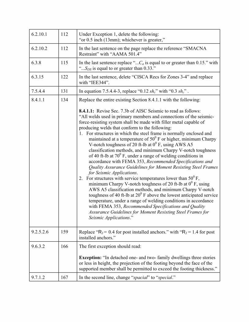
6.2.10.1 112 Under Exception 1, delete the following: “or 0.5 inch (13mm); whichever is greater,”
6.2.10.2 112 In the last sentence on the page replace the reference “SMACNA Restraint” with “AAMA 501.4”
6.3.8 115 In the last sentence replace “...Ca is equal to or greater than 0.15.” with “...SDS is equal to or greater than 0.33.”
6.3.15 122 In the last sentence, delete “CISCA Recs for Zones 3-4” and replace with “IEE344”.
7.5.4.4 131 In equation 7.5.4.4-3, replace “0.12 shc” with “0.3 shc” .
8.4.1.1 134 Replace the entire existing Section 8.4.1.1 with the following: 8.4.1.1: Revise Sec. 7.3b of AISC Seismic to read as follows: “All welds used in primary members and connections of the seismic-force-resisting system shall be made with filler metal capable of producing welds that conform to the following: 1. For structures in which the steel frame is normally enclosed and
maintained at a temperature of 500 F or higher, minimum Charpy V-notch toughness of 20 ft-lb at 00 F, using AWS A5 classification methods, and minimum Charpy V-notch toughness of 40 ft-lb at 700 F, under a range of welding conditions in accordance with FEMA 353, Recommended Specifications and Quality Assurance Guidelines for Moment Resisting Steel Frames for Seismic Applications.
2. For structures with service temperatures lower than 500 F, minimum Charpy V-notch toughness of 20 ft-lb at 00 F, using AWS A5 classification methods, and minimum Charpy V-notch toughness of 40 ft-lb at 200 F above the lowest anticipated service temperature, under a range of welding conditions in accordance with FEMA 353, Recommended Specifications and Quality Assurance Guidelines for Moment Resisting Steel Frames for Seismic Applications.”
9.2.5.2.6 159 Replace “R3 = 0.4 for post installed anchors.” with “R3 = 1.4 for post installed anchors.”
9.6.3.2 166 The first exception should read: Exception: “In detached one- and two- family dwellings three stories or less in height, the projection of the footing beyond the face of the supported member shall be permitted to exceed the footing thickness.”
9.7.1.2 167 In the second line, change “spacial” to “special.”

11.1.2 175 Replace Sec. 11.1.2 to include the expanded reference titles of ACI 530 and 530.1 as follows: “11.1.2 Reference Documents: The designation and title of documents cited in this chapter are listed in this section. ACI 318 American Concrete Institute (ACI), Building Code
Requirements for Structural Concrete, excluding Appendix A, 1999
ACI 530/ASCE 5/ American Concrete Institute (ACI), Building TMS 402 Code Requirements for Masonry Structures, 1999 ACI 530.1/ASCE 6/American Concrete Institute (ACI), Specifications TMS 602 for Masonry Structures, 1999 Compliance with specific provisions of ACI 530/ASCE 5/TMS 402 is mandatory where required by this chapter.”
11.2.1 180 Expand the reference titles in two places for ACI 530.1 to read: “ACI 530.1/ASCE 6/TMS 602”
11.3.2 180 Expand the reference title for ACI 530.1 to read: “ACI 530.1/ASCE 6/TMS 602”
11.3.7.5 182 Expand the reference title for ACI 530 in the last sentence to read: “ACI 530/ASCE 5/TMS 402”
11.3.10.5.2 185 Replace the second sentence, “For grouted stack bond masonry, tension parallel to the bed joints for in-plane bending shall be assumed to be resisted only by the continuous grout core section.” with “For grouted stack bond masonry, in-plane flexural tension parallel to the bed joints for in-plane bending shall be assumed to be resisted only by the continuous horizontally grout cross section.”
11.6.3.5 196 Replace Equation (11.6.3.5-1) with the following:
2
1 91 4 0n n n
h hfo r rrfP A = −
′Φ Φ 9<
11.7.31 197 Replace “M/Vdv < 0.25:” with M/Vdv # 0.25:” and place it before equation (11.7.3.1-2).
11.7.31 198 At the top of the page replace “M/Vdv < 1.00:” with M/Vdv $1.00:”
11.7.31 198 In the last sentence of the section replace “Vm (max) =” with “Vn (max) =”.
11.9.3 200 In the last sentence of paragraph “c” replace “84 tie diameters.” with “48 tie diameters.”
11.12.2.1 207 Expand the reference titles in two places for ACI 530 to read: “ACI 530/ASCE 5/TMS 402”
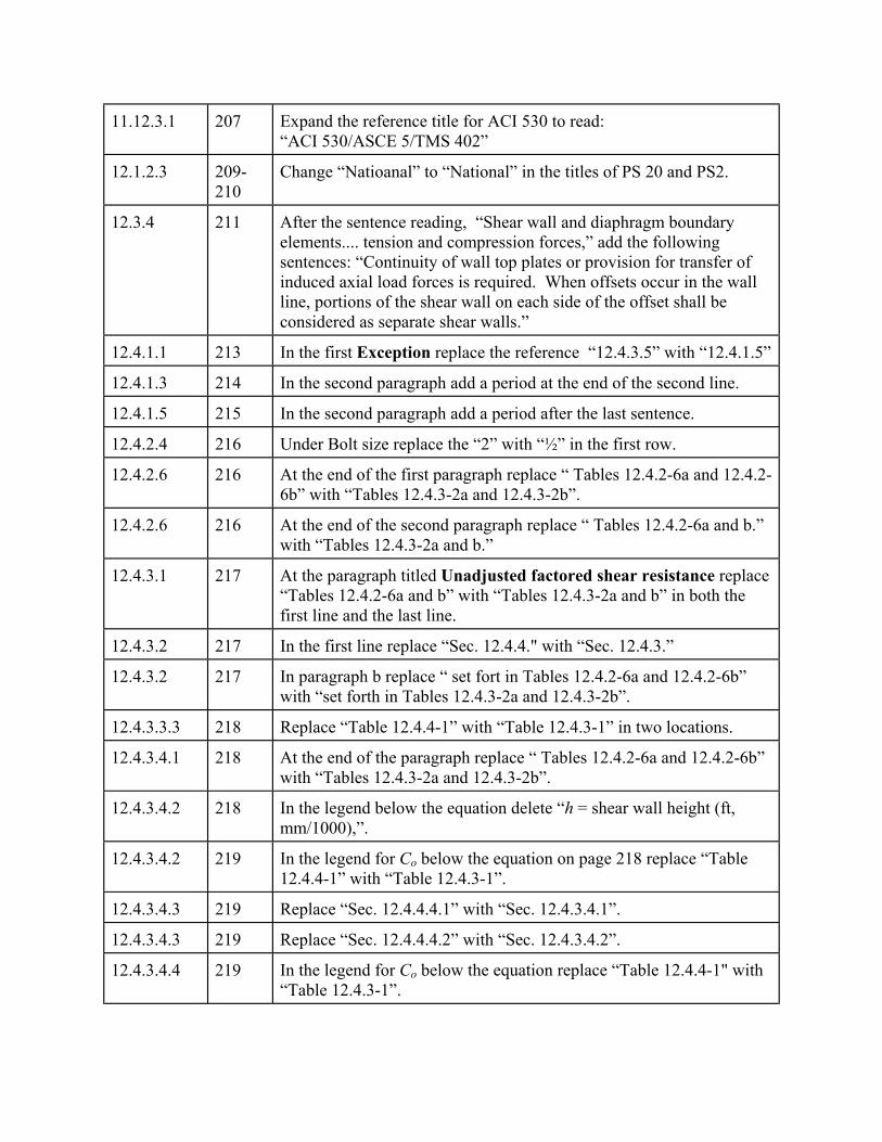
11.12.3.1 207 Expand the reference title for ACI 530 to read: “ACI 530/ASCE 5/TMS 402”
12.1.2.3 209-210
Change “Natioanal” to “National” in the titles of PS 20 and PS2.
12.3.4 211 After the sentence reading, “Shear wall and diaphragm boundary elements.... tension and compression forces,” add the following sentences: “Continuity of wall top plates or provision for transfer of induced axial load forces is required. When offsets occur in the wall line, portions of the shear wall on each side of the offset shall be considered as separate shear walls.”
12.4.1.1 213 In the first Exception replace the reference “12.4.3.5” with “12.4.1.5”
12.4.1.3 214 In the second paragraph add a period at the end of the second line.
12.4.1.5 215 In the second paragraph add a period after the last sentence.
12.4.2.4 216 Under Bolt size replace the “2” with “½” in the first row.
12.4.2.6 216 At the end of the first paragraph replace “ Tables 12.4.2-6a and 12.4.2-6b” with “Tables 12.4.3-2a and 12.4.3-2b”.
12.4.2.6 216 At the end of the second paragraph replace “ Tables 12.4.2-6a and b.” with “Tables 12.4.3-2a and b.”
12.4.3.1 217 At the paragraph titled Unadjusted factored shear resistance replace “Tables 12.4.2-6a and b” with “Tables 12.4.3-2a and b” in both the first line and the last line.
12.4.3.2 217 In the first line replace “Sec. 12.4.4." with “Sec. 12.4.3.”
12.4.3.2 217 In paragraph b replace “ set fort in Tables 12.4.2-6a and 12.4.2-6b” with “set forth in Tables 12.4.3-2a and 12.4.3-2b”.
12.4.3.3.3 218 Replace “Table 12.4.4-1” with “Table 12.4.3-1” in two locations.
12.4.3.4.1 218 At the end of the paragraph replace “ Tables 12.4.2-6a and 12.4.2-6b” with “Tables 12.4.3-2a and 12.4.3-2b”.
12.4.3.4.2 218 In the legend below the equation delete “h = shear wall height (ft, mm/1000),”.
12.4.3.4.2 219 In the legend for Co below the equation on page 218 replace “Table 12.4.4-1” with “Table 12.4.3-1”.
12.4.3.4.3 219 Replace “Sec. 12.4.4.4.1” with “Sec. 12.4.3.4.1”.
12.4.3.4.3 219 Replace “Sec. 12.4.4.4.2” with “Sec. 12.4.3.4.2”.
12.4.3.4.4 219 In the legend for Co below the equation replace “Table 12.4.4-1" with “Table 12.4.3-1”.
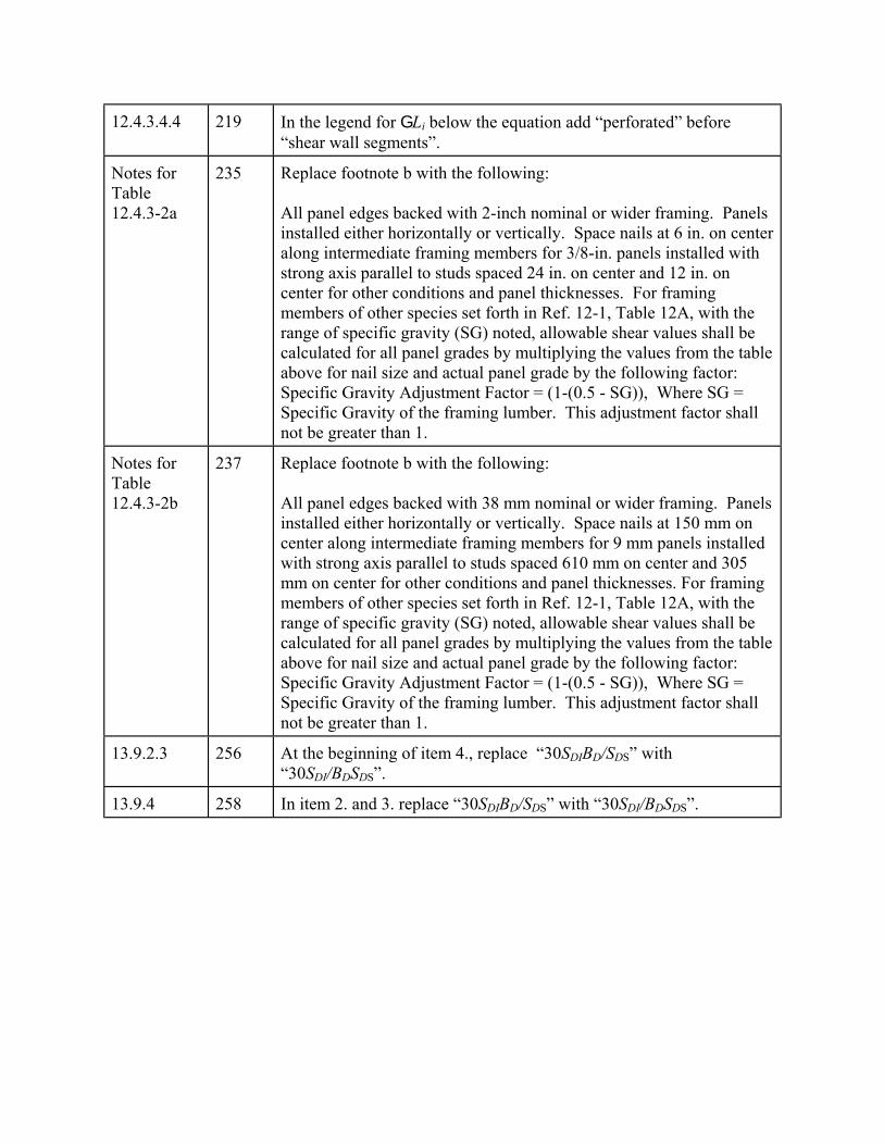
12.4.3.4.4 219 In the legend for GLi below the equation add “perforated” before “shear wall segments”.
Notes for Table 12.4.3-2a
235 Replace footnote b with the following: All panel edges backed with 2-inch nominal or wider framing. Panels installed either horizontally or vertically. Space nails at 6 in. on center along intermediate framing members for 3/8-in. panels installed with strong axis parallel to studs spaced 24 in. on center and 12 in. on center for other conditions and panel thicknesses. For framing members of other species set forth in Ref. 12-1, Table 12A, with the range of specific gravity (SG) noted, allowable shear values shall be calculated for all panel grades by multiplying the values from the table above for nail size and actual panel grade by the following factor: Specific Gravity Adjustment Factor = (1-(0.5 - SG)), Where SG = Specific Gravity of the framing lumber. This adjustment factor shall not be greater than 1.
Notes for Table 12.4.3-2b
237 Replace footnote b with the following: All panel edges backed with 38 mm nominal or wider framing. Panels installed either horizontally or vertically. Space nails at 150 mm on center along intermediate framing members for 9 mm panels installed with strong axis parallel to studs spaced 610 mm on center and 305 mm on center for other conditions and panel thicknesses. For framing members of other species set forth in Ref. 12-1, Table 12A, with the range of specific gravity (SG) noted, allowable shear values shall be calculated for all panel grades by multiplying the values from the table above for nail size and actual panel grade by the following factor: Specific Gravity Adjustment Factor = (1-(0.5 - SG)), Where SG = Specific Gravity of the framing lumber. This adjustment factor shall not be greater than 1.
13.9.2.3 256 At the beginning of item 4., replace “30SDIBD/SDS” with “30SDI/BDSDS”.
13.9.4 258 In item 2. and 3. replace “30SDIBD/SDS” with “30SDI/BDSDS”.

14.5.1 294 Replace item 2 with the following: 2. For nonbuilding systems that have an R value provided in Table
14.5.2.1, the minimum specified value in Eq. 5.4.1.1-3 shall be replaced by:
CS = 0.14 SDS I (14.5.1-1)
and the minimum value specified in Eq. 5.4.1.1-4 shall be replaced by:
CS = 0.8 S1 I/R (14.5.1-2)
14.5.3 298 In the first sentence, replace the first reference to “Sec. 5.4.3" with “Sec. 5.3.”
14.7.3.2 302 Paragraph c. replace the sentence, “For tanks and vessels not covered by an approved national standard, the vertical seismic force shall be defined as 67 percent of the equivalent lateral force.” with “For tanks and vessels not covered by an approved national standard, the vertical seismic force shall be based on a vertical ground acceleration defined as 67 percent of the design horizontal ground acceleration.”
14.7.3.6.1.5 308 In the last sentence of the first paragraph under a., replace “base shear” with “base friction”.
14.7.3.6.1.5 308 In the first sentence of the second paragraph under a.., replace “V” with “W”.
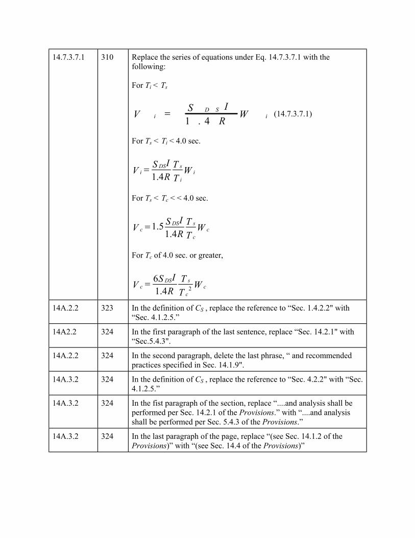
14.7.3.7.1 310 Replace the series of equations under Eq. 14.7.3.7.1 with the following: For Ti < Ts
1 . 4D S
i iISV W
R= (14.7.3.7.1)
For Ts < Ti < 4.0 sec.
1.4sDS
i ii
IS TV WR T
=
For Ts < Tc < < 4.0 sec.
1.51.4
sDSc c
c
IS TV WR T
=
For Tc of 4.0 sec. or greater,
261.4
sDSc c
c
IS TV WR T
=
14A.2.2 323 In the definition of CS , replace the reference to “Sec. 1.4.2.2" with “Sec. 4.1.2.5.”
14A2.2 324 In the first paragraph of the last sentence, replace “Sec. 14.2.1" with “Sec.5.4.3".
14A.2.2 324 In the second paragraph, delete the last phrase, “ and recommended practices specified in Sec. 14.1.9".
14A.3.2 324 In the definition of CS , replace the reference to “Sec. 4.2.2" with “Sec. 4.1.2.5.”
14A.3.2 324 In the fist paragraph of the section, replace “....and analysis shall be performed per Sec. 14.2.1 of the Provisions.” with “....and analysis shall be performed per Sec. 5.4.3 of the Provisions.”
14A.3.2 324 In the last paragraph of the page, replace “(see Sec. 14.1.2 of the Provisions)” with “(see Sec. 14.4 of the Provisions)”
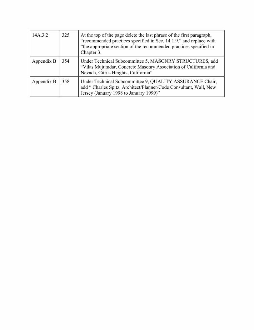
14A.3.2 325 At the top of the page delete the last phrase of the first paragraph, “recommended practices specified in Sec. 14.1.9.” and replace with “the appropriate section of the recommended practices specified in Chapter 3.
Appendix B 354 Under Technical Subcommittee 5, MASONRY STRUCTURES, add “Vilas Mujumdar, Concrete Masonry Association of California and Nevada, Citrus Heights, California”
Appendix B 358 Under Technical Subcommittee 9, QUALITY ASSURANCE Chair, add “ Charles Spitz, Architect/Planner/Code Consultant, Wall, New Jersey (January 1998 to January 1999)”

1
Chapter 1
GENERAL PROVISIONS
1.1 PURPOSE: The NEHRP Recommended Provisions for Seismic Regulations for NewBuildings and Other Structures (referred to hereinafter as the Provisions) present criteria for thedesign and construction of structures to resist earthquake ground motions. The purposes of theProvisions are as follows:
1. To provide minimum design criteria for structures appropriate to their primary function anduse considering the need to protect the health, safety, and welfare of the general public byminimizing the earthquake-related risk to life and
2. To improve the capability of essential facilities and structures containing substantialquantities of hazardous materials to function during and after design earthquakes.
The design earthquake ground motion levels specified herein could result in both structural andnonstructural damage. For most structures designed and constructed according to the Provisions,structural damage from the design earthquake ground motion would be repairable althoughperhaps not economically so. For essential facilities, it is expected that the damage from thedesign earthquake ground motion would not be so severe as to preclude continued occupancyand function of the facility. The actual ability to accomplish these goals depends upon a numberof factors including the structural framing type, configuration, materials, and as-built details ofconstruction. For ground motions larger than the design levels, the intent of the Provisions isthat there be a low likelihood of structural collapse.
1.2 SCOPE AND APPLICATION:
1.2.1 Scope: The Provisions shall apply to the design and construction of structures includingadditions, change of use, and alterations to resist the effects of earthquake motions. Everystructure, and portion thereof, shall be designed and constructed to resist the effects of earth-quake motions as prescribed by the Provisions.
Exceptions:
1. Detached one- and two-family dwellings in Seismic Design Categories A, B, and Care exempt from all requirements of the Provisions.
2. Detached one- and two-family wood frame dwellings that are designed and con-structed in accordance with the conventional light frame construction requirementsin Sec. 12.5 are exempt from all other requirements of the Provisions.
3. Agricultural storage structures intended only for incidental human occupancy areexempt from all requirements of the Provisions.
4. Structures located where S1 is less than or equal to 0.04 and Ss is less than or equal to0.15 shall only be required to comply with Sec. 5.2.5 and Sec. 5.2.6.1 and tanks in
2000 Provisions, Chapter 1
2
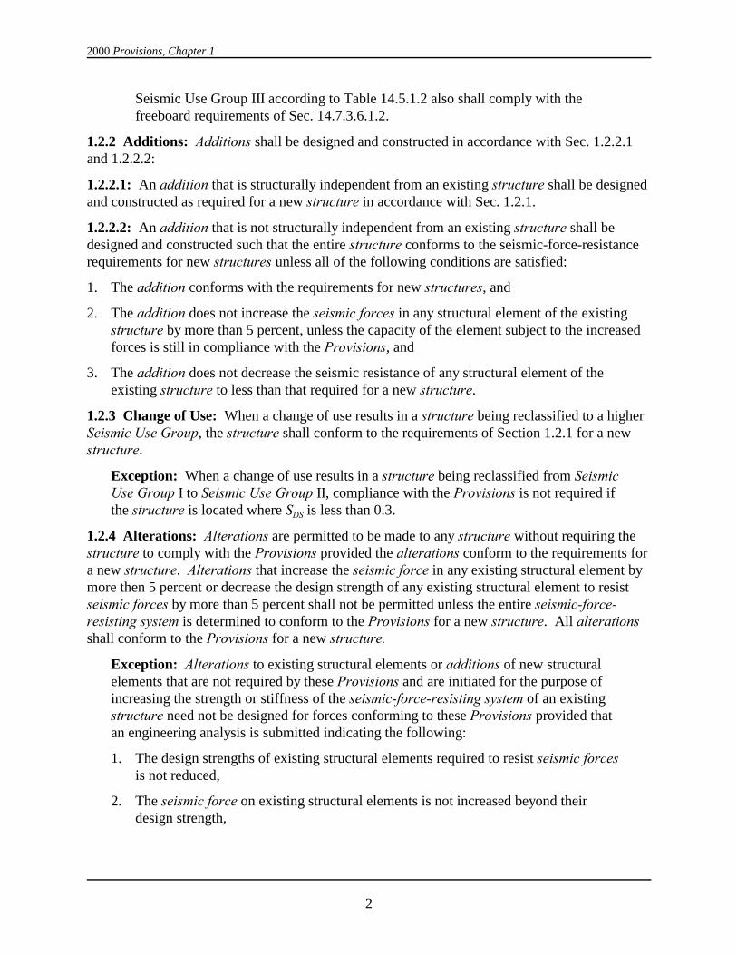
Seismic Use Group III according to Table 14.5.1.2 also shall comply with thefreeboard requirements of Sec. 14.7.3.6.1.2.
1.2.2 Additions: Additions shall be designed and constructed in accordance with Sec. 1.2.2.1and 1.2.2.2:
1.2.2.1: An addition that is structurally independent from an existing structure shall be designedand constructed as required for a new structure in accordance with Sec. 1.2.1.
1.2.2.2: An addition that is not structurally independent from an existing structure shall bedesigned and constructed such that the entire structure conforms to the seismic-force-resistancerequirements for new structures unless all of the following conditions are satisfied:
1. The addition conforms with the requirements for new structures, and
2. The addition does not increase the seismic forces in any structural element of the existingstructure by more than 5 percent, unless the capacity of the element subject to the increasedforces is still in compliance with the Provisions, and
3. The addition does not decrease the seismic resistance of any structural element of theexisting structure to less than that required for a new structure.
1.2.3 Change of Use: When a change of use results in a structure being reclassified to a higherSeismic Use Group, the structure shall conform to the requirements of Section 1.2.1 for a newstructure.
Exception: When a change of use results in a structure being reclassified from SeismicUse Group I to Seismic Use Group II, compliance with the Provisions is not required ifthe structure is located where SDS is less than 0.3.
1.2.4 Alterations: Alterations are permitted to be made to any structure without requiring the structure to comply with the Provisions provided the alterations conform to the requirements fora new structure. Alterations that increase the seismic force in any existing structural element bymore then 5 percent or decrease the design strength of any existing structural element to resistseismic forces by more than 5 percent shall not be permitted unless the entire seismic-force-resisting system is determined to conform to the Provisions for a new structure. All alterationsshall conform to the Provisions for a new structure.
Exception: Alterations to existing structural elements or additions of new structuralelements that are not required by these Provisions and are initiated for the purpose ofincreasing the strength or stiffness of the seismic-force-resisting system of an existingstructure need not be designed for forces conforming to these Provisions provided thatan engineering analysis is submitted indicating the following:
1. The design strengths of existing structural elements required to resist seismic forcesis not reduced,
2. The seismic force on existing structural elements is not increased beyond theirdesign strength,

General Provisions
3
3. New structural elements are detailed and connected to the existing structuralelements as required by the Provisions, and
4. New or relocated nonstructural elements are detailed and connected to existing ornew structural elements as required by the Provisions.
1.2.5 Alternate Materials and Alternate Means and Methods of Construction: Alternatematerials and alternate means and methods of construction to those prescribed in the Provisionsare permitted if approved by the authority having jurisdiction. Substantiating evidence shall besubmitted demonstrating that the proposed alternate, for the purpose intended, will be at leastequal in strength, durability, and seismic resistance.
1.3 SEISMIC USE GROUPS: All structures shall be assigned to one of the Seismic UseGroups described in Sec 1.3.1 through 1.3.3.
1.3.1 Seismic Use Group III: Seismic Use Group III structures are those having essentialfacilities that are required for post-earthquake recovery and those containing substantialquantities of hazardous substances including:
1. Fire, rescue, and police stations
2. Hospitals
3. Designated medical facilities having emergency treatment facilities
4. Designated emergency preparedness centers
5. Designated emergency operation centers
6. Designated emergency shelters
7. Power generating stations or other utilities required as emergency back-up facilities forSeismic Use Group III facilities
8. Emergency vehicle garages and emergency aircraft hangars
9. Designated communication centers
10. Aviation control towers and air traffic control centers
11. Structures containing sufficient quantities of toxic or explosive substances deemed to behazardous to the public
12. Water treatment facilities required to maintain water pressure for fire suppression.
1.3.2 Seismic Use Group II: Seismic Use Group II structures are those that have a substantialpublic hazard due to occupancy or use including:
1. Covered structures whose primary occupancy is public assembly with a capacity greater than300 persons
2. Educational structures through the 12th grade with a capacity greater than 250 persons
3. Day care centers with a capacity greater than 150 persons

2000 Provisions, Chapter 1
4
4. Medical facilities with greater than 50 resident incapacitated patients not otherwise desig-nated a Seismic Use Group III structure
5. Jails and detention facilities
6. All structures with a capacity greater than 5,000 persons
7. Power generating stations and other public utility facilities not included in Seismic UseGroup III and required for continued operation
8. Water treatment facilities required for primary treatment and disinfection for potable water
9. Waste water treatment facilities required for primary treatment
1.3.3 Seismic Use Group I: Seismic Use Group I structures are those not assigned to SeismicUse Groups III or II.
1.3.4 Multiple Use: Structures having multiple uses shall be assigned the classification of theuse having the highest Seismic Use Group except in structures having two or more portions thatare structurally separated in accordance with Sec. 5.2.8, each portion shall be separatelyclassified. Where a structurally separated portion of a structure provides access to, egress from,or shares life safety components with another portion having a higher Seismic Use Group, thelower portion shall be assigned the same rating as the higher.
1.3.5 Seismic Use Group III Structure Access Protection: Where operational access to aSeismic Use Group III structure is required through an adjacent structure, the adjacent structureshall conform to the requirements for Seismic Use Group III structures. Where operationalaccess is less than 10 ft (3 m) from an interior lot line or less than 10 ft (3 m) from anotherstructure, access protection from potential falling debris shall be provided by the owner of theSeismic Use Group III structure.
1.4 OCCUPANCY IMPORTANCE FACTOR: An occupancy importance factor, I, shall beassigned to each structure in accordance with Table 1.4.
TABLE 1.4 Occupancy Importance Factors
Seismic Use Group I
I 1.0
II 1.25
III 1.5
55
Chapter 2
GLOSSARY AND NOTATIONS
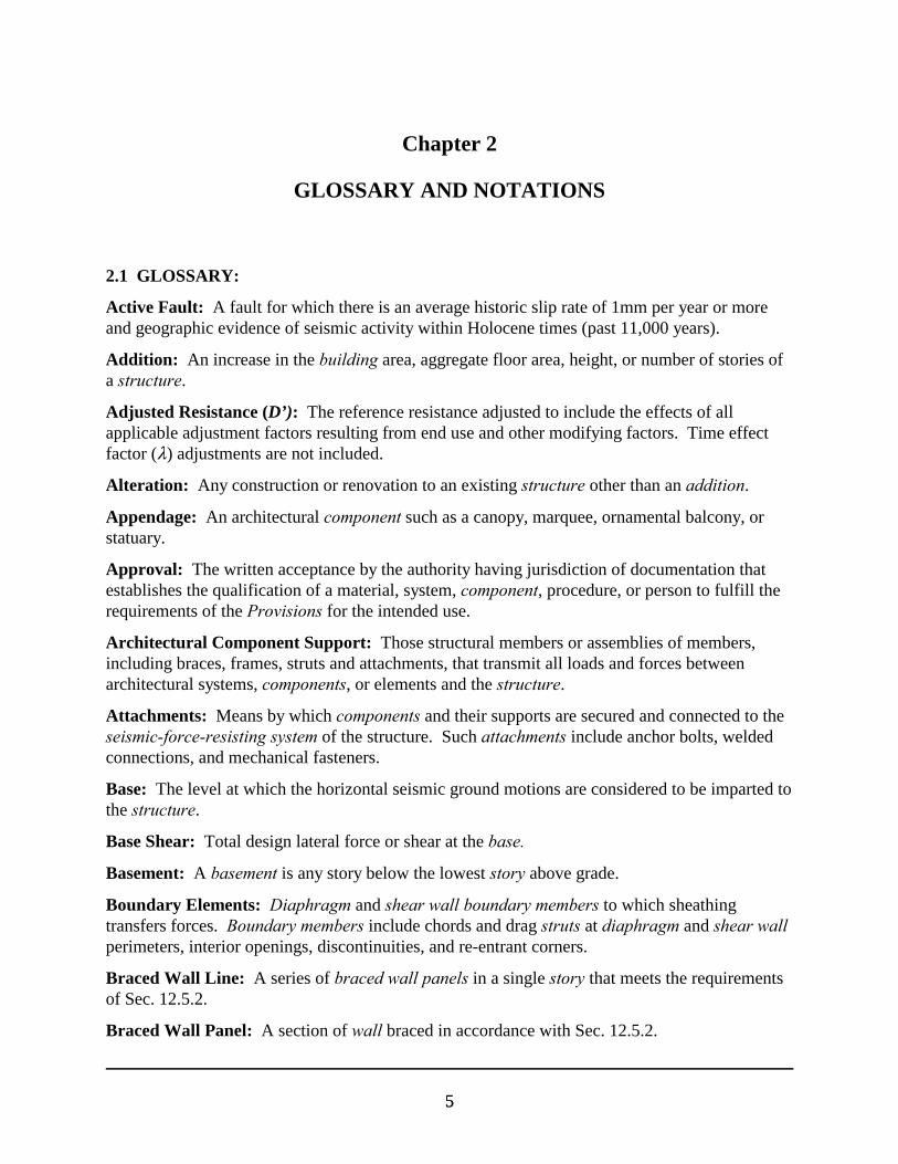
2.1 GLOSSARY:
Active Fault: A fault for which there is an average historic slip rate of 1mm per year or moreand geographic evidence of seismic activity within Holocene times (past 11,000 years).
Addition: An increase in the building area, aggregate floor area, height, or number of stories ofa structure.
Adjusted Resistance (D’): The reference resistance adjusted to include the effects of allapplicable adjustment factors resulting from end use and other modifying factors. Time effectfactor (8) adjustments are not included.
Alteration: Any construction or renovation to an existing structure other than an addition.
Appendage: An architectural component such as a canopy, marquee, ornamental balcony, orstatuary.
Approval: The written acceptance by the authority having jurisdiction of documentation thatestablishes the qualification of a material, system, component, procedure, or person to fulfill therequirements of the Provisions for the intended use.
Architectural Component Support: Those structural members or assemblies of members,including braces, frames, struts and attachments, that transmit all loads and forces betweenarchitectural systems, components, or elements and the structure.
Attachments: Means by which components and their supports are secured and connected to theseismic-force-resisting system of the structure. Such attachments include anchor bolts, weldedconnections, and mechanical fasteners.
Base: The level at which the horizontal seismic ground motions are considered to be imparted tothe structure.
Base Shear: Total design lateral force or shear at the base.
Basement: A basement is any story below the lowest story above grade.
Boundary Elements: Diaphragm and shear wall boundary members to which sheathingtransfers forces. Boundary members include chords and drag struts at diaphragm and shear wallperimeters, interior openings, discontinuities, and re-entrant corners.
Braced Wall Line: A series of braced wall panels in a single story that meets the requirementsof Sec. 12.5.2.
Braced Wall Panel: A section of wall braced in accordance with Sec. 12.5.2.

2000 Provisions, Chapter 2
66
Building: Any structure whose use could include shelter of human occupants.
Boundary Members: Portions along wall and diaphragm edges strengthened by longitudinaland transverse reinforcement and/or structural steel members.
Cantilevered Column System: A seismic-force-resisting system in which lateral forces areresisted entirely by columns acting as cantilevers from the foundation.
Component: A part or element of an architectural, electrical, mechanical, or structural system.
Component, Equipment: A mechanical or electrical component or element that is partof a mechanical and/or electrical system within or without a building system.
Component, Flexible: Component, including its attachments, having a fundamentalperiod greater than 0.06 sec.
Component, Rigid: Component, including its attachments, having a fundamental periodless than or equal to 0.06 sec.
Concrete:
Plain Concrete: Concrete that is either unreinforced or contains less reinforcement thanthe minimum amount specified in ACI 318 for reinforced concrete.
Reinforced Concrete: Concrete reinforced with no less than the minimum amountrequired by ACI 318, prestressed or non-prestressed, and designed on the assumption thatthe two materials act together in resisting forces.
Confined Region: The portion of reinforced concrete component in which the concrete isconfined by closely spaced special transverse reinforcement restraining the concrete in directionsperpendicular to the applied stress.
Construction Documents: The written, graphic, electronic, and pictorial documents describingthe design, locations, and physical characteristics of the project required to verify compliancewith the Provisions.
Container: A large-scale independent component used as a receptacle or a vessel toaccommodate plants, refuse, or similar uses.
Coupling Beam: A beam that is used to connect adjacent concrete wall piers to make them acttogether as a unit to resist lateral loads.
Damping Device: A flexible structural element of the damping system that dissipates energydue to relative motion of each end of the device. Damping devices include all pins, bolts gussetplates, brace extensions, and other components required to connect damping devices to the otherelements of the structure. Damping devices may be classified as either displacement-dependentor velocity-dependent, or a combination thereof, and may be configured to act in either a linear ornonlinear manner.
Damping System: The collection of structural elements that includes all the individual dampingdevices, all structural elements or bracing required to transfer forces from damping devices to the
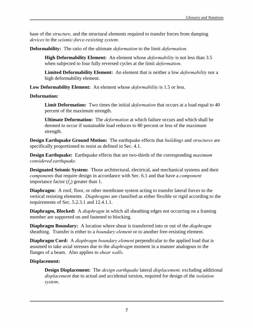
Glossary and Notations
77
base of the structure, and the structural elements required to transfer forces from dampingdevices to the seismic-force-resisting system.
Deformability: The ratio of the ultimate deformation to the limit deformation.
High Deformability Element: An element whose deformability is not less than 3.5when subjected to four fully reversed cycles at the limit deformation.
Limited Deformability Element: An element that is neither a low deformability nor ahigh deformability element.
Low Deformability Element: An element whose deformability is 1.5 or less.
Deformation:
Limit Deformation: Two times the initial deformation that occurs at a load equal to 40percent of the maximum strength.
Ultimate Deformation: The deformation at which failure occurs and which shall bedeemed to occur if sustainable load reduces to 80 percent or less of the maximumstrength.
Design Earthquake Ground Motion: The earthquake effects that buildings and structures arespecifically proportioned to resist as defined in Sec. 4.1.
Design Earthquake: Earthquake effects that are two-thirds of the corresponding maximumconsidered earthquake.
Designated Seismic System: Those architectural, electrical, and mechanical systems and theircomponents that require design in accordance with Sec. 6.1 and that have a componentimportance factor (Ip) greater than 1.
Diaphragm: A roof, floor, or other membrane system acting to transfer lateral forces to thevertical resisting elements. Diaphragms are classified as either flexible or rigid according to therequirements of Sec. 5.2.3.1 and 12.4.1.1.
Diaphragm, Blocked: A diaphragm in which all sheathing edges not occurring on a framingmember are supported on and fastened to blocking.
Diaphragm Boundary: A location where shear is transferred into or out of the diaphragmsheathing. Transfer is either to a boundary element or to another free-resisting element.
Diaphragm Cord: A diaphragm boundary element perpendicular to the applied load that isassumed to take axial stresses due to the diaphragm moment in a manner analogous to theflanges of a beam. Also applies to shear walls.
Displacement:
Design Displacement: The design earthquake lateral displacement, excluding additionaldisplacement due to actual and accidental torsion, required for design of the isolationsystem.
2000 Provisions, Chapter 2
88
Total Design Displacement: The design earthquake lateral displacement, includingadditional displacement due to actual and accidental torsion, required for design of theisolation system or an element thereof.
Total Maximum Displacement: The maximum considered earthquake lateraldisplacement, including additional displacement due to actual and accidental torsion,required for verification of the stability of the isolation system or elements thereof, designof structure separations, and vertical load testing of isolator unit prototypes.
Displacement-Dependent Damping Device: The force response of a displacement-dependentdamping device is primarily a function of the relative displacement between each end of thedevice. The response is substantially independent of the relative velocity between each end ofthe device and/or the excitation frequency.
Displacement Restraint System: A collection of structural elements that limits lateraldisplacement of seismically isolated structures due to maximum considered earthquake groundshaking.
Drag Strut (Collector, Tie, Diaphragm Strut): A diaphragm or shear wall boundary elementparallel to the applied load that collects the transfered diaphragm shear forces to the vertical-force-resisting elements or distributes forces within the diaphragm or shear wall. A drag strutoften is an extension of a boundary element that transfers forces into the diaphragm or shearwall.
Effective Damping: The value of equivalent viscous damping corresponding to energydissipated during cyclic response of the isolation system.
Effective Stiffness: The value of lateral force in the isolation system, or an element thereof,divided by the corresponding lateral displacement.
Enclosure: An interior space surrounded by walls.
Equipment Support: Those structural members or assemblies of members or manufacturedelements, including braces, frames, legs, lugs, snuggers, hangers or saddles, that transmit gravityload and operating load between the equipment and the structure.
Essential Facility: A facility or structure required for post-earthquake recovery.
Factored Resistance (8N8N8N8N D): Reference resistance multiplied by the time effect and resistancefactors. This value must be adjusted for other factors such as size effects, moisture conditions,and other end-use factors.
Flexible Equipment Connections: Those connections between equipment components thatpermit rotational and/or transitional movement without degradation of performance. Examplesincluded universal joints, bellows expansion joints, and flexible metal hose.
Frame:
Braced Frame: An essentially vertical truss, or its equivalent, of the concentric oreccentric type that is provided in a building frame system or dual frame system to resistshear.
Glossary and Notations
99
Concentrically Braced Frame (CBF): A braced frame in which the membersare subjected primarily to axial forces.
Eccentrically Braced Frame (EBF): A diagonally braced frame in which atleast one end of each brace frames into a beam a short distance from a beam-column joint or from another diagonal brace.
Ordinary Concentrically Braced Frame (OCBF): A steel concentricallybraced frame in which members and connections are designed in accordance withthe provisions of AISC Seismic without modification.
Special Concentrically Braced Frame (SCBF): A steel or composite steel andconcrete concentrically braced frame in which members and connections aredesigned for ductile behavior
Moment Frame: A frame provided with restrained connections between the beams andcolumns to permit the frame to resist lateral forces through the flexural rigidity andstrength of its members.
Intermediate Moment Frame: A moment frame of reinforced concrete meetingthe detailing requirements of ACI 318, of structural steel meeting the detailingrequirements of AISC Seismic, or of composite construction meeting therequirements of AISC Seismic.
Ordinary Moment Frame: A moment frame or reinforced concrete conformingto the requirements of ACI 318 exclusive of Chapter 21, of structural steelmeeting the detailing requirements of AISC Seismic or of composite constructionmeeting the requirements of AISC Seismic
Special Moment Frame: A moment frame of reinforced concrete meeting thedetailing requirements of ACI 318, of structural steel meeting the detailingrequirements of AISC Seismic, or of composite construction meeting therequirements of AISC Seismic.
Frame System:
Building Frame System: A structural system with an essentially complete space framesystem providing support for vertical loads. Seismic-force resistance is provided by shearwalls or braced frames.
Dual Frame System: A structural system with an essentially complete space framesystem providing support for vertical loads. Seismic force resistance is provided by amoment resisting frame and shear walls or braced frames as prescribed in Sec. 5.2.2.1
Space Frame System: A structural system composed of interconnected members, otherthan bearing walls, that is capable of supporting vertical loads and that also may provideresistance to shear.
Glazed Curtain Wall: A nonbearing wall that extends beyond the edges of the building floorslabs and includes a glazing material installed in the curtain wall framing.

2000 Provisions, Chapter 2
1010
Glazed Storefront: A nonbearing wall that is installed between floor slabs typically includingentrances and includes a glazing material installed in the storefront framing.
Grade Plane: A reference plane representing the average of the finished ground level adjoiningthe structure at the exterior walls. Where the finished ground level slopes away from the exteriorwalls, the reference plane shall be established by the lowest points within the area between thebuildings and the lot line or, where the lot line is more than 6 ft (1829 mm) from the structure,between the structure and a point 6 ft (1829 mm) from the structure.
Hazardous Contents: A material that is highly toxic or potentially explosive and in sufficientquantity to pose a significant life-safety threat to the general public if an uncontrolled releasewere to occur.
High Temperature Energy Source: A fluid, gas, or vapor whose temperature exceeds 220degrees F (378 K).
Inspection, Special: The observation of the work by the special inspector to determinecompliance with the approved construction documents and the Provisions.
Continuous Special Inspection: A full-time observation of the work by an approvedspecial inspector who is present in the area where work is being performed.
Periodic Special Inspection: The part-time or intermittent observation of the work byan approved special inspector who is present in the area where work has been or is beingperformed.
Inspector, Special (who shall be identified as the Owner’s Inspector): A person approved bythe authority having jurisdiction as being qualified to perform special inspection required by theapproved quality assurance plan. The quality assurance personnel of a fabricator is permitted tobe approved by the authority having jurisdiction as a special inspector.
Inverted Pendulum Type Structures: Structures that have a large portion of their massconcentrated near the top and, thus, have essentially one degree of freedom in horizontaltranslation. The structures are usually T-shaped with a single column supporting the beams orframing at the top.
Isolation Interface: The boundary between the upper portion of the structure, which is isolated,and the lower portion of the structure, which moves rigidly with the ground.
Isolation System: The collection of structural elements that includes all individual isolatorunits, all structural elements that transfer force between elements of the isolation system, and allconnections to other structural elements. The isolation system also includes the wind-restraintsystem, energy-dissipation devices, and/or the displacement restraint system if such systems anddevices are used to meet the design the requirements of Chapter 13.
Isolator Unit: A horizontally flexible and vertically stiff structural element of the isolationsystem that permits large lateral deformations under design seismic load. An isolator unit ispermitted to be used either as part of or in addition to the weight-supporting system of thestructure.

Glossary and Notations
1111
Joint: The portion of a column bounded by the highest and lowest surfaces of the other membersframing into it.
Load:
Dead Load: The gravity load due to the weight of all permanent structural andnonstructural components of a building such as walls, floors, roofs, and the operatingweight of fixed service equipment.
Gravity Load (W): The total dead load and applicable portions of other loads as definedin Sec. 5.3.2.
Live Load: The load superimposed by the use and occupancy of the building notincluding the wind load, earthquake load, or dead load; see Sec. 5.3.
Maximum Considered Earthquake Ground Motion: The most severe earthquake effectsconsidered by the Provisions as defined in Sec. 4.1.
Nonbuilding Structure: A structure, other than a building, constructed of a type included inChapter 14 and within the limits of Sec. 14.1.1.
Occupancy Importance Factor: A factor assigned to each structure according to its SeismicUse Group as prescribed in Sec. 1.4.
Owner: Any person, agent, firm, or corporation having a legal or equitable interest in theproperty.
Partition: A nonstructural interior wall that spans from floor to ceiling, to the floor or roofstructure immediately above, or to subsidiary structural members attached to the structure above.
P-Delta Effect: The secondary effect on shears and moments of structural members induced dueto displacement of the structure.
Quality Assurance Plan: A detailed written procedure that establishes the systems andcomponents subject to special inspection and testing.
Reference Resistence: The resistence (force or moment as appropriate) of a member orconnection computed at the reference end use conditions.
Registered Design Professional: An architect or engineer registered or licensed to practiceprofessional architecture or engineering as defined by statuary requirements of the professionalregistrations laws of the state in which the project is to be constructed.
Roofing Unit: A unit of roofing material weighing more than 1 pound (0.5 kg).
Seismic Design Category: A classification assigned to a structure based on its Seismic UseGroup and the severity of the design earthquake ground motion at the site.
Seismic-Force-Resisting System: That part of the structural system that has been considered inthe design to provide the required resistence to the shear wall prescribed herein.
Seismic Forces: The assumed forces prescribed herein, related to the response of the structureto earthquake motions, to be used in the design of the structure and its components.
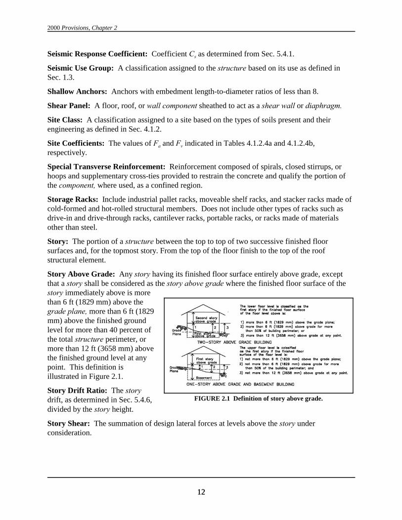
2000 Provisions, Chapter 2
1212
FIGURE 2.1 Definition of story above grade.
Seismic Response Coefficient: Coefficient Cs as determined from Sec. 5.4.1.
Seismic Use Group: A classification assigned to the structure based on its use as defined inSec. 1.3.
Shallow Anchors: Anchors with embedment length-to-diameter ratios of less than 8.
Shear Panel: A floor, roof, or wall component sheathed to act as a shear wall or diaphragm.
Site Class: A classification assigned to a site based on the types of soils present and theirengineering as defined in Sec. 4.1.2.
Site Coefficients: The values of Fa and Fv indicated in Tables 4.1.2.4a and 4.1.2.4b,respectively.
Special Transverse Reinforcement: Reinforcement composed of spirals, closed stirrups, orhoops and supplementary cross-ties provided to restrain the concrete and qualify the portion ofthe component, where used, as a confined region.
Storage Racks: Include industrial pallet racks, moveable shelf racks, and stacker racks made ofcold-formed and hot-rolled structural members. Does not include other types of racks such asdrive-in and drive-through racks, cantilever racks, portable racks, or racks made of materialsother than steel.
Story: The portion of a structure between the top to top of two successive finished floorsurfaces and, for the topmost story. From the top of the floor finish to the top of the roofstructural element.
Story Above Grade: Any story having its finished floor surface entirely above grade, exceptthat a story shall be considered as the story above grade where the finished floor surface of thestory immediately above is morethan 6 ft (1829 mm) above thegrade plane, more than 6 ft (1829mm) above the finished groundlevel for more than 40 percent ofthe total structure perimeter, ormore than 12 ft (3658 mm) abovethe finished ground level at anypoint. This definition isillustrated in Figure 2.1.
Story Drift Ratio: The storydrift, as determined in Sec. 5.4.6,divided by the story height.
Story Shear: The summation of design lateral forces at levels above the story underconsideration.

Glossary and Notations
1313
Strength:
Design Strength: Nominal strength multiplied by the strength reduction factor, N.
Nominal Strength: Strength of a member or cross section calculated in accordance withthe requirements and assumptions of the strength design methods of the Provisions (orthe reference standards) before application of any strength reduction factors.
Required Strength: Strength of a member, cross section, or connection required toresist factored loads or related internal moments and forces in such combinations asstipulated by the Provisions.
Structure: That which is built or constructed and limited to buildings and nonbuildingstructures as defined herein.
Structural Observations: The visual observations performed by the registered designprofessional in responsible charge (or another registered design professional) to determine thatthe seismic-force-resisting system is constructed in general conformance with the constructiondocuments.
Wood Structural Panel: A wood-based panel product that meets the requirements of PS 1 orPS 2 and is bonded with a waterproof adhesive. Included under this designation is plywood,oriented strand board, and composite panels.
Subdiaphragm: A portion of a diaphragm used to transfer wall anchorage forces to thediaphragm cross ties.
Testing Agency: A company or corporation that provides testing and/or inspection services. The person in responsible charge of the special inspector(s) and the testing services shall be aregistered design professional.
Tie-Down (Hold-Down): A device used to resist uplift of the chords of shear walls. Thesedevices are intended to resist load without significant slip between the device and the shear wallchord or be shown with cyclic testing to not reduce the wall capacity and ductility.
Time Effect Factor: A factor applied to the adjusted resistence to account for effects of durationload.
Torsional Force Distribution: The distribution of horizontal shear wall through the rigiddiaphragm when the center of the mass of the structure at the level under consideration does notcoincide with the center of the rigidity (sometimes referred to as diaphragm rotation).
Toughness: The ability of a material to absorb energy without losing significant strength.
Utility or Service Interface: The connection of the structure’s mechanical and electricaldistribution systems to the utility or service company’s distribution system.
Velocity-Dependent Damping Device: The force-displacement relation for a velocity-dependent damping device is primarily a function of the relative velocity between each end of thedevice and also may be a function of the relative displacement between each end of the device.

2000 Provisions, Chapter 2
1414
Veneers: Facings or ornamentations of brick, concrete, stone, tile, or similar materials attachedto a backing.
Wall: A component that has a slope of 60 degrees or greater with the horizontal plane used toenclose or divide space.
Bearing Wall: An exterior or interior wall providing support for vertical loads.
Cripple Wall: A framed stud wall, less than 8 ft (2400 mm) in height, extending fromthe top of the foundation to the underside of the lowest floor framing. Cripple walls canoccur in both engineered structures and conventional construction.
Light-Framed Wall: A wall with wood or steel studs.
Light-Framed Wood Shear Wall: A wall constructed with wood studs and sheathedwith material rated for shear resistance.
Nonbearing Wall: An exterior or interior wall that does not provide support for verticalloads other than its own weight or as permitted by the building code administered by theauthority having jurisdiction.
Nonstructural Wall: All walls other than bearing walls or shear walls.
Shear Wall (Vertical Diaphragm): A wall designed to resist lateral forces parallel tothe plane of the wall (sometimes referred to as a vertical diaphragm).
Wall System, Bearing: A structural system with bearing walls providing support for all ormajor portions of the vertical loads. Shear walls or braced frames provide seismic-forceresistance.
Wind-Restraint System: The collection of structural elements that provides restraint of theseismic-isolated structure for wind loads. The wind-restraint system may be either an integralpart of isolator units or a separate device.
2.2 NOTATIONS:
A, B, C, D, E, F Site classes as defined in Sec. 4.1.2.
Ab Area (in.2 or mm2) of anchor bolt or stud in Chapters 6 and 11.
Ach Cross sectional-area (in.2 or mm2) of a component measured to the outsideof the special lateral reinforcement.
An Net-cross sectional area of masonry (in.2 or mm2) in Chapter 11.
Ao The area of the load-carrying foundation (ft2 or m2).
Ap Projected area on the masonry surface of a right circular cone for anchorbolt allowable shear and tension calculations (in.2 or mm2) in Chapter 11.
As The area of an assumed failure surface taken as a pyramid in Eq. 2.4.1-3 orin Chapter 9.
As Cross-sectional area of reinforcement (in.2 or mm2) in Chapters 6 and 11.
Glossary and Notations
1515
Ash Total cross-sectional area of hoop reinforcement (in.2 or mm2), includingsupplementary cross-ties, having spacing of sh and crossing a section witha core dimension of hc.
Avd Required area of leg (in.2 or mm2) of diagonal reinforcement.
Ax The torsional amplification factor.
ab Length of compressive stress block (in. or mm) in Chapter 11.
ad The incremental factor related to P-delta effects in Sec. 5.4.5.
ap The component amplification factor as defined in Sec. 6.1.3.
Ba Nominal axial strength of an anchor bolt (lb or N) in Chapter 11.
BD Numerical coefficient as set forth in Table 13.3.3.1 for effective dampingequal to $D.
BID Numerical coefficient as set forth in Table A13.3.1 for effective dampingequal to $ml (m=1) and period of structure equal to T11.
Bm Numerical coefficient as set forth in Table 13.3.3.1 for effective dampingequal $M
BIM Numerical coefficient as set forth in Table A13.3.1 for effective dampingequal to $mM (m=1) and period of structure equal to TIM.
BmD Numerical coefficient as set forth in Table A13.3.1 for effective dampingequal to $ml and period of structure equal to Tm.
BmM Numerical coefficient as set forth in Table A13.3.1 for effective dampingequal to $mM and period of structure equal to Tm.
BR Numerical coefficient as set forth in Table A13.3.1 for effective dampingequal to $R and the period of structure equal to TR.
Bv Nominal shear strength of an anchor bolt (lb or N) in Chapter 11.
BV-1 Numerical coefficient as set forth in Table A13.3.1 for effective dampingequal to the sum of viscous damping in the fundamental mode of vibrationof the structure in the direction of interest, $Vm (m = 1), plus inherentdamping, $l, and period of structure equal to T1.
b The shortest plan dimension of the structure, in ft (mm), measuredperpendicular to d.
ba Factored axial force on an anchor bolt (lb or N) in Chapter 11.
bv Factored shear force on an anchor bolt (lb or N) in Chapter 11.
bw Web width (in.or mm) in Chapter 11.
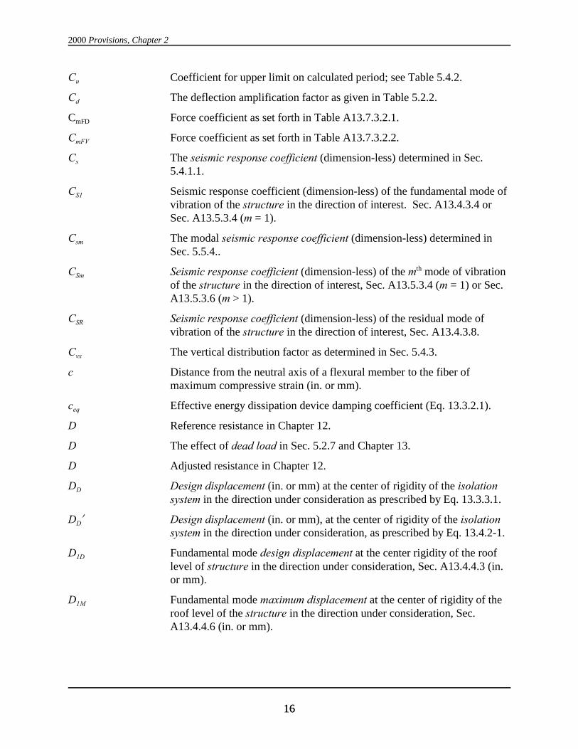
2000 Provisions, Chapter 2
1616
Cu Coefficient for upper limit on calculated period; see Table 5.4.2.
Cd The deflection amplification factor as given in Table 5.2.2.
CmFD Force coefficient as set forth in Table A13.7.3.2.1.
CmFV Force coefficient as set forth in Table A13.7.3.2.2.
Cs The seismic response coefficient (dimension-less) determined in Sec.5.4.1.1.
CS1 Seismic response coefficient (dimension-less) of the fundamental mode ofvibration of the structure in the direction of interest. Sec. A13.4.3.4 orSec. A13.5.3.4 (m = 1).
Csm The modal seismic response coefficient (dimension-less) determined inSec. 5.5.4..
CSm Seismic response coefficient (dimension-less) of the mth mode of vibrationof the structure in the direction of interest, Sec. A13.5.3.4 (m = 1) or Sec.A13.5.3.6 (m > 1).
CSR Seismic response coefficient (dimension-less) of the residual mode ofvibration of the structure in the direction of interest, Sec. A13.4.3.8.
Cvx The vertical distribution factor as determined in Sec. 5.4.3.
c Distance from the neutral axis of a flexural member to the fiber ofmaximum compressive strain (in. or mm).
ceq Effective energy dissipation device damping coefficient (Eq. 13.3.2.1).
D Reference resistance in Chapter 12.
D The effect of dead load in Sec. 5.2.7 and Chapter 13.
D Adjusted resistance in Chapter 12.
DD Design displacement (in. or mm) at the center of rigidity of the isolationsystem in the direction under consideration as prescribed by Eq. 13.3.3.1.
DD! Design displacement (in. or mm), at the center of rigidity of the isolationsystem in the direction under consideration, as prescribed by Eq. 13.4.2-1.
D1D Fundamental mode design displacement at the center rigidity of the rooflevel of structure in the direction under consideration, Sec. A13.4.4.3 (in.or mm).
D1M Fundamental mode maximum displacement at the center of rigidity of theroof level of the structure in the direction under consideration, Sec.A13.4.4.6 (in. or mm).
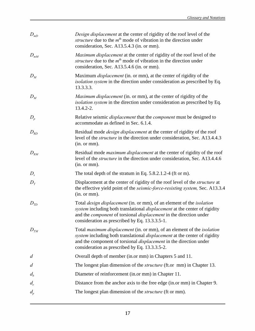
Glossary and Notations
1717
DmD Design displacement at the center of rigidity of the roof level of thestructure due to the mth mode of vibration in the direction underconsideration, Sec. A13.5.4.3 (in. or mm).
DmM Maximum displacement at the center of rigidity of the roof level of thestructure due to the mth mode of vibration in the direction underconsideration, Sec. A13.5.4.6 (in. or mm).
DM Maximum displacement (in. or mm), at the center of rigidity of theisolation system in the direction under consideration as prescribed by Eq.13.3.3.3.
DM Maximum displacement (in. or mm), at the center of rigidity of theisolation system in the direction under consideration as prescribed by Eq.13.4.2-2.
Dp Relative seismic displacement that the component must be designed toaccommodate as defined in Sec. 6.1.4.
DRD Residual mode design displacement at the center of rigidity of the rooflevel of the structure in the direction under consideration, Sec. A13.4.4.3(in. or mm).
DRM Residual mode maximum displacement at the center of rigidity of the rooflevel of the structure in the direction under consideration, Sec. A13.4.4.6(in. or mm).
Ds The total depth of the stratum in Eq. 5.8.2.1.2-4 (ft or m).
DY Displacement at the center of rigidity of the roof level of the structure atthe effective yield point of the seismic-force-resisting system, Sec. A13.3.4(in. or mm).
DTD Total design displacement (in. or mm), of an element of the isolationsystem including both translational displacement at the center of rigidityand the component of torsional displacement in the direction underconsideration as prescribed by Eq. 13.3.3.5-1.
DTM Total maximum displacement (in. or mm), of an element of the isolationsystem including both translational displacement at the center of rigidityand the component of torsional displacement in the direction underconsideration as prescribed by Eq. 13.3.3.5-2.
d Overall depth of member (in.or mm) in Chapters 5 and 11.
d The longest plan dimension of the structure (ft.or mm) in Chapter 13.
db Diameter of reinforcement (in.or mm) in Chapter 11.
de Distance from the anchor axis to the free edge (in.or mm) in Chapter 9.
dp The longest plan dimension of the structure (ft or mm).

2000 Provisions, Chapter 2
1818
E The effect of horizontal and vertical earthquake-induced forces (Sec. 5.2.7and Chapter 13).
Eloop Energy dissipated (kip-inches or kN-mm), in an isolator unit during a fullcycle of reversible load over a test displacement range from )+ to )- asmeasured by the area enclosed by the loop of the loop of the force-deflation curve.
Em Chord modulus of elasticity of masonry (psi or MPa) in Chapter 11.
Es Modulus of elasticity of reinforcement (psi or MPa) in Chapter 11.
Ev Modulus of rigidity of masonry (psi or Mpa) in Chapter 11.
e The actual eccentricity ( ft or mm), measured in plan between the center ofmass of the structure above the isolation interface and the center ofrigidity of the isolation system, plus accidental eccentricity (ft or mm),taken as 5 percent the maximum building dimension perpendicular to thedirection of the force under consideration.
Fa Acceleration-based site coefficient (at 0.3 sec period).
F- Maximum negative force in an isolator unit during a single cycle ofprototype testing a displacement amplitude of )-.
F- Positive force in kips (kN) in an isolator unit during a single cycle ofprototype testing at a displacement amplitude of )-.
Fi, Fn, Fx The portion of the seismic base shear, V, induced at level i, n, or x,respectively, as determined in Sec. 5.3.4 (kip or kN).
Fi1 Inertial force at Level i (or mass point i) in the fundamental mode ofvibration of the structure in the direction of interest, Sec. A13.4.3.9.
Fim Inertial force at Level i (or mass point i) in the mth mode of vibration of thestructure in the direction of interest, Sec. A13.5.3.7.
FiR Inertial force at Level i (or mass point i) in the residual mode of vibrationof the structure in the direction of interest, Sec. A13.4.3.9.
Fp The seismic design force center of gravity and distributed relative to thecomponent’s weight distribution as determined in Sec. 6.1.3.
Fp The induced seismic force on connections of anchorages as determined inSec. 5.2.6.1.2
Fu Specified ultimate tensile strength (psi or MPa) of an anchor (Sec. 9.2.4).
Fv Velocity-based site coefficient (at 1.0 sec period).
Fx Total force distributed over the height of the structure above the isolationinterface as prescribed by Eq. 13.3.5.
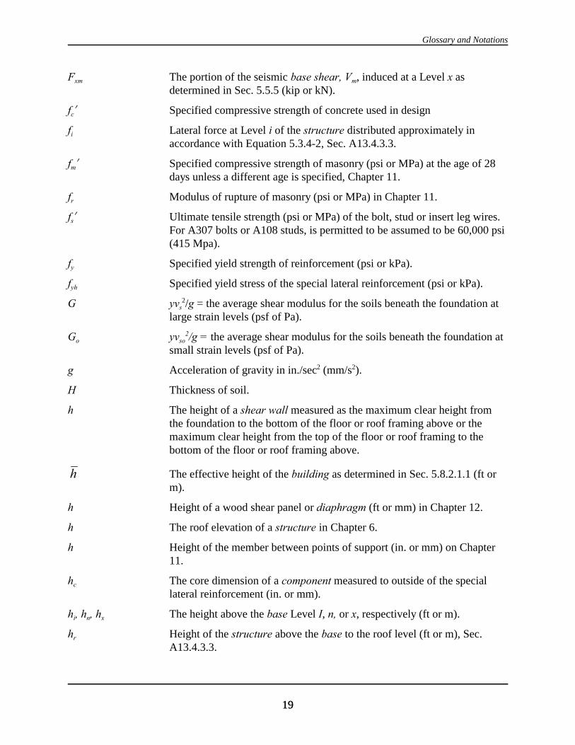
Glossary and Notations
1919
Fxm The portion of the seismic base shear, Vm, induced at a Level x asdetermined in Sec. 5.5.5 (kip or kN).
fc! Specified compressive strength of concrete used in design
fi Lateral force at Level i of the structure distributed approximately inaccordance with Equation 5.3.4-2, Sec. A13.4.3.3.
fm! Specified compressive strength of masonry (psi or MPa) at the age of 28days unless a different age is specified, Chapter 11.
fr Modulus of rupture of masonry (psi or MPa) in Chapter 11.
fs! Ultimate tensile strength (psi or MPa) of the bolt, stud or insert leg wires. For A307 bolts or A108 studs, is permitted to be assumed to be 60,000 psi(415 Mpa).
fy Specified yield strength of reinforcement (psi or kPa).
fyh Specified yield stress of the special lateral reinforcement (psi or kPa).
G yvs2/g = the average shear modulus for the soils beneath the foundation at
large strain levels (psf of Pa).
Go yvso2/g = the average shear modulus for the soils beneath the foundation at
small strain levels (psf of Pa).
g Acceleration of gravity in in./sec2 (mm/s2).
H Thickness of soil.
h The height of a shear wall measured as the maximum clear height fromthe foundation to the bottom of the floor or roof framing above or themaximum clear height from the top of the floor or roof framing to thebottom of the floor or roof framing above.
The effective height of the building as determined in Sec. 5.8.2.1.1 (ft orhm).
h Height of a wood shear panel or diaphragm (ft or mm) in Chapter 12.
h The roof elevation of a structure in Chapter 6.
h Height of the member between points of support (in. or mm) on Chapter11.
hc The core dimension of a component measured to outside of the speciallateral reinforcement (in. or mm).
hi, hn, hx The height above the base Level I, n, or x, respectively (ft or m).
hr Height of the structure above the base to the roof level (ft or m), Sec.A13.4.3.3.

2000 Provisions, Chapter 2
2020
hsx The story height below Level x = hx - hx-1 (ft. Or m).
I The occupancy importance factor in Sec. 1.4.
Icr Moment of inertia of the cracked section (in.4 or mm) in Chapter 11.
In Moment of inertia of the net cross-sectional area of a member (in.4 ormm4) in Chapter 11.
Io The static moment of inertia of the load-carrying foundation , see Sec.5.5.2.1 (in.4 or mm4).
Ip The component importance factor as prescribed in Sec. 6.1.5.
I The building level referred to by the subscript I; I = 1 designates the firstlevel above the base.
Kp The stiffness of component or attachment as defined in Sec. 6.3.3.
Ky The lateral stiffness of the foundation as defined in Sec. 5.8.2.1.1 (lb/in. orN/m).
K2 The rocking stiffness of the foundation as defined in Sec. 5.8.2.1.1(ft.lb/degree or N m/rad).
KL/r The lateral slenderness of a compression member measured in terms of itseffective buckling length, KL, and the least radius of gyration of themember cross section, r.
k The distribution exponent given in Sec. 5.4.3.
Kdmax Maximum effective stiffness, in kips/inch (kN/mm) of the isolation systemat the design displacement in the horizontal direction under considerationas prescribed by Eq. 13.9.5.1-1.
KDmin Minimum effective stiffness (kips/inch or kN/mm) of the isolation systemat the design displacement in the horizontal direction under considerationas prescribed by Eq. 13.9.5.1-2.
Kmax Maximum effective stiffness (kips/inch or kN/mm) of the isolation systemat the maximum displacement in the horizontal direction underconsideration as prescribed by Eq 13.9.5.1-3.
KMin Minimum effective stiffness (kips/inch or kN/mm) of the isolation systemat the maximum displacement in the horizontal direction underconsideration, as prescribed by Eq. 13.9.5.1-4.
keff Effective stiffness of an isolator unit as prescribed by Eq. 13.9.3-1.
The stiffness of the building as determined in Sec. 5.8.2.1.1 (lb/ft or N/m).k
L The overall length of the building (ft or m) at the base in the directionbeing analyzed.

Glossary and Notations
2121
L Length of bracing member (in. or mm) in Chapter 8.
L Length of coupling beam between coupled shear walls in Chapter 11 (in.or mm).
L The effect of live load in Chapter 13.
Lo The overall length of the side of the foundation in the direction beinganalyzed, Sec. 5.8.2.1.2 (ft or m).
l The dimension of a diaphragm perpendicular to the direction ofapplication of force. For open-front structures, l is the length from theedge of the diaphragm at the open front to the vertical resisting elementsparallel to the direction of the applied force. For a cantilevereddiaphragm, l is the length from the edge of the diaphragm at the openfront to the vertical resisting elements parallel to the direction of theapplied force.
Rb Effective embedment length of anchor bolt (in. or mm) in Chapter 11.
Rbc Anchor bolt edge distance (in. or mm) in Chapter 11.
Rd Development length (in. or mm) in Chapter 11.
Rdh Equivalent development length for a standard hook (in. or mm) in Chapter11.
R1d Minimum lap splice length (in. or mm) in Chapter 11.
M Moment on a masonry section due to un-factored loads (in. lb or N @ mm)in Chapter 11.
Ma Maximum moment in a member at deflation is computed (in. @lb or N @mm) in Chapter 11.
Mcr Cracking moment strength of the masonry (in. @lb or N @mm) in Chapter11.
Md Design moment strength (in. @lb or N @mm) in Chapter 11.
Mf The foundation overturning design moment as defined in Sec. 5.4.5 (ft @kipor kN @m).
Mo, Mo1 The overturning moment at the foundation-soil interface as determined inSec. 5.5.6 and 5.8.3 (ft @lb or N @m)
Mnb Un-factored ultimate moment capacity at balanced strain conditions.
Mt The torsional moment resulting from the location of the building masses(ft @kip or kN @m).
Mta The accidental torsional moment as determined in Sec. 5.4.4.2 (ft @kip orkN @m).
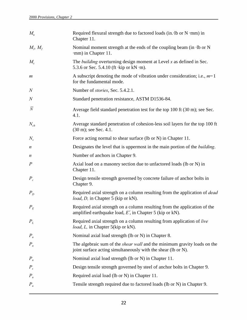
2000 Provisions, Chapter 2
2222
Mu Required flexural strength due to factored loads (in.@lb or N @mm) inChapter 11.
M1, M2 Nominal moment strength at the ends of the coupling beam (in @lb or N@mm) in Chapter 11.
Mx The building overturning design moment at Level x as defined in Sec.5.3.6 or Sec. 5.4.10 (ft @kip or kN @m).
m A subscript denoting the mode of vibration under consideration; i.e., m=1for the fundamental mode.
N Number of stories, Sec. 5.4.2.1.
N Standard penetration resistance, ASTM D1536-84.
Average field standard penetration test for the top 100 ft (30 m); see Sec.N
4.1.
Nch Average standard penetration of cohesion-less soil layers for the top 100 ft(30 m); see Sec. 4.1.
Nv Force acting normal to shear surface (lb or N) in Chapter 11.
n Designates the level that is uppermost in the main portion of the building.
n Number of anchors in Chapter 9.
P Axial load on a masonry section due to unfactored loads (lb or N) inChapter 11.
Pc Design tensile strength governed by concrete failure of anchor bolts inChapter 9.
PD Required axial strength on a column resulting from the application of deadload, D, in Chapter 5 (kip or kN).
PE Required axial strength on a column resulting from the application of theamplified earthquake load, E!, in Chapter 5 (kip or kN).
PL Required axial strength on a column resulting from application of liveload, L, in Chapter 5(kip or kN).
Pn Nominal axial load strength (lb or N) in Chapter 8.
Pn The algebraic sum of the shear wall and the minimum gravity loads on thejoint surface acting simultaneously with the shear (lb or N).
Pn Nominal axial load strength (lb or N) in Chapter 11.
Ps Design tensile strength governed by steel of anchor bolts in Chapter 9.
Pu Required axial load (lb or N) in Chapter 11.
Pu Tensile strength required due to factored loads (lb or N) in Chapter 9.

Glossary and Notations
2323
Pu’ Required axial strength on a brace (kip or kN) in Chapter 8.
Px The total unfactored vertical design load at and above level x (kip or kN).
PI Plasticity index, ASTM D4318-93.
QDSD Force in an element of the damping system required to resist designseismic forces of displacement-dependent damping devices, Sec.A13.7.3.2.
QE The effect of horizontal seismic forces (kip or kN) in Chapters 5 and 13.
QmDSV Forces in an element of the damping system required to resist designseismic forces of velocity-dependent damping devices due to the mth modeof vibration of structure in the direction of interest, Sec. A13.7.3.2.
QmSFRS Force in a element of the damping system equal to the design seismic forceof the mth mode of vibration of the seismic force resisting system in thedirection of interest, A13.7.3.2.
Qv The load equivalent to the effect of the horizontal and vertical shearstrength of the vertical segment in the Appendix to Chapter 8.
qH Hysteresis loop adjustment factor as determined in Sec. A13.3.3.
R The response modification coefficient as given in Table 5.2.2.
R1 Numerical coefficient related to the type of lateral-force-resisting systemabove the isolation system as set forth in Table 13.3.4.2 for seismicallyisolated structures.
Rp The component response modification system factor as defined in Chapter6.
r The characteristic length of the foundation as defined in Chapter 5 (ft orm)
r Radius of gyration (in. or mm) in Chapter 11.
ra, rm The characteristic foundation length defined in Sec. 5.8.2.1.1 (ft or m).
rx The ratio of the design story shear resisted by the most heavily loadedsingle element in the story, in direction x, to the total story shear.
S Section modules based on net cross sectional area of a wall (in.3 or mm3)in Chapter 11.
S1 The maximum considered earthquake, 5 percent damped, spectral responseacceleration at a period of 1 second as defined in Chapter 4.
SD1 The design, 5 percent damped, spectral response acceleration at a period of1 second as defined in Chapter 4..

2000 Provisions, Chapter 2
2424
SDS The design, 5 percent damped, spectral response acceleration at shortperiods as defined in Chapter 4.
SM1 The maximum considered earthquake, 5 percent damped, spectral responseacceleration at a period of one second adjusted for site class effects asdefined in Chapter 4.
SMS The maximum considered earthquake, 5 percent damped, spectral responseacceleration at short periods adjusted for site class effects as defined inChapter 4.
Ss The mapped maximum considered earthquake, 5 percent damped, spectralresponse acceleration at short periods as defined in Chapter 4.
Spr Probable strength of precast element connectors (Sec. 9.1.1.12).
Average undrained shear strength in top 100 ft (30.5 m); see Sec. 4.1.2.3,su
ASTM D2166-91 or ASTM D2850-87.
sh Spacing of special lateral reinforcement (in. or mm). .
T The period (sec) of the fundamental mode of vibration of the structure inthe direction of interest as determined in Chapter 5.
T, T1 The effective fundamental period (sec) of the building as determined inChapter 5.
T1 Period, in seconds, of the fundamental mode of vibration of the structurein the direction of interest, Sec. A13.4.3.3.
Ta The approximate fundamental period (sec) of the building as determinedin Chapter 5.
TD Effective period, in seconds (sec), of the seismically isolated structure atthe design displacement in the direction under consideration as prescribedby Eq. 13.3.3.2.
T1D Effective period, in seconds, of the fundamental mode of vibration of thestructure at the design displacement in the direction under consideration,as prescribed by Sec. A13.4.3.5 or Sec. A13.5.3.5.
T1M Effective period, in seconds, of the fundamental mode of vibration of thestructure at the maximum displacement in the direction underconsideration, as prescribed by Sec. A13.4.3.5 or Sec. A13.5.3.5.
TM Effective period, in seconds (sec), of the seismically isolated structure atthe maximum displacement in the direction under consideration asprescribed by Eq. 13.3.3.4.
Tm The period (sec) of the mth mode of vibration of the structure in thedirection of interest determined in Chapter 5.
Glossary and Notations
2525
Tm Period, in seconds, of the mth mode of vibration of the structure in thedirection under consideration, Sec. A13.5.3.6.
T0 0.2SD1/SDS
Tp The fundamental period (sec) of the component and its attachment(s) asdefined in Sec. 6.3.3.
TR Period, in seconds, of the residual mode of vibration of the structure in thedirection under consideration, Sec. A13.4.3.7.
TS SDI/SDS.
T4 Net tension in steel cable due to dead load, prestress, live load, andseismic load.
t Specified wall thickness dimension or least lateral dimension of a column(in. or mm) in Chapter 11.
tc Thickness of masonry cover over reinforcing bars measured from thesurface of the masonry to the surface of the reinforcing bars (in. or mm) inChapter 11.
V The total design shear at the base of the structure in the direction ofinterest, as determined using the procedure of Sec. 5.3, including Sec.5.4.1 (kip or kN).
V Shear on a masonry section due to un-factored loads (lb or N) in Chapter11.
Vb The total lateral seismic design force or shear on elements of the isolationsystem or elements below the isolation system as prescribed by Eq.13.3.4.1.
Vm Shear strength provided by masonry (lb or N) in Chapter 11.
Vm Design value of the seismic base shear of the mth mode of vibration of thestructure in the direction of interest, Sec. 5.4.5 or Sec. A13.5.3.2 (kip orkN).
Vmm Minimum allowable value of base shear permitted for design of theseismic-force-resisting system of the structure in the direction of interest,Sec. A13.2.4.1 (kip or kN).
Vn Nominal shear strength (lb or N) in Chapter 11.
VR Design value of the seismic base shear of the residual mode of vibrationof the structure in a given direction, as determined in Sec. A13.4.3.6 (kipor kN).
Vs The total lateral seismic design factor or shear on elements above theisolation system as prescribed by Eq. 13.3.4.2.

2000 Provisions, Chapter 2
2626
Vs Shear strength provided by shear reinforcement (lb or N) in Chapters 6 and11.
Vt The design value of the seismic base shear as determined in Chapter 5(kip or N).
Vu Required shear strength (lb or N) due to factored loads in Chapters 6 and11.
Vx The seismic design shear in Story x as determined in Chapter 5 (kip orkN).
V1 The portion of seismic base shear, V, contributed by the fundamentalmode as determined in Chapter 5 (kip or kN).
Vl The design value of the seismic base shear of the fundamental mode in agiven direction as determined in Chapter 5 (kip or kN).
)V The reduction in V as determined in Chapter 5 (kip or kN).
)V1 The reduction of V1 as determined in Chapter 5 (kp or kN).
vs The average shear wave velocity for the soils beneath the foundation atlarge strain levels as determined in chapter 5 (ft/s or m/s).
Average shear wave velocity in top one 100 ft (30 m); see Chapter 4.vs
vso The average shear wave velocity for the soils beneath the foundation atsmall strain levels as determined in chapter 5 (ft/s or m/s).
W The total gravity load of the structure defined in Chapter 5 (kip or kN). For calculation of a seismically isolated building structure, the period, W,is the total seismic dead load weight of the structure above the isolationsystem (kip or kN).
The effective gravity load of the structure as defined in Chapter 5 andW
5.5.3 (kip or kN).
Effective fundamental mode gravity load of structure including portions1W
of the live load determined in accordance with Eq. 5.4.5-2 for m = 1 (kipor kN).
Effective residual mode gravity load of the structure determined inWR
accordance with Eq. A13.4.3.7-3 (kip or kN).
WD The energy dissipated per cycle at the story displacement for the designearthquake.

Glossary and Notations
2727
The effective gravity load of mth mode of vibration of the structureWm
determined in Chapter 5 (kip or kN).
Wp Component operating weight (lb or N).
w Width of wood shear panel or diaphragm in Chapter 9 (ft or mm).
w Moisture content (in percent), ASTM D2216-92.
w The dimension of a diaphragm or shear wall in the direction of applicationof force.
wi, wx The portion of the total gravity load, W, located or assigned to Level I or x(kip or kN).
z The level under consideration; x = 1 designates the first level above thebase.
x Elevation in structure of a component addressed by Chapter 6.
y Elevation difference between points of attachment in Chapter 6.
y The distance, in ft (mm), between the center of rigidity of the isolationsystem rigidity and the element of interest measured perpendicular to thedirection of seismic loading under consideration.
" The relative weight density of the structure and the soil as determined inChapter 5.
" Angle between diagonal reinforcement and longitudinal axis of themember (degree or rad).
" Velocity power term relating damping device force to damping devicevelocity.
$ Ratio of shear demand to shear capacity for the story between Level x andx-1.
$ The fraction of critical damping for the coupled structure-foundationsystem determined in Chapter 5.
$D Effective damping of the isolation system at the design displacement asprescribed by Eq. 13.9.5.2-1.
$eff Effective damping of the isolation system as prescribed by Eq. 13.9.3-2.
$HD Component of effective damping of the structure in the direction ofinterest due to post-yield hysteric behavior of the seismic-force-resistingsystem and elements of the damping system at effective ductility demandµD, Sec. A13.3.2.2.
$HM Component of effective damping of the structure in the direction ofinterest due to post-yield hysteric behavior of the seismic-force-resisting
2000 Provisions, Chapter 2
2828
system and elements of the damping system at effective ductility demand,µM, Sec. A13.3.2.2.
$I Component of effective damping of the structure due to the inherentdissipation of energy by elements of the structure, at or just below theeffective yield displacement of the seismic-force-resisting system, Sec.A13.3.2.1.
$M Effective damping of the isolation system at the maximum displacement asprescribed by Eq. 13.9.5.2-2.
$mD Total effective damping of the mth mode of vibration of the structure in thedirection of interest at the design displacement, Sec. A13.3.2.
$mM Total effective damping of the mth mode of vibration of the structure in thedirection of interest at the maximum displacement , Sec. A13.3.2.
$o The foundation damping factor as specified in Chapter 5.
$R Total effective damping in the residual mode of vibration of the structurein the direction of interest, calculated in accordance with Sec. A13.3.2 (µD =1.0 and µM = 1.0).
$Vm Component of effective damping of the mth mode of vibration of thestructure in the direction of interest due to viscous dissipation of energy bythe damping system, at or just below the effective yield displacement ofthe seismic-force-resisting system, Sec. A13.3.2.3.
( Lightweight concrete factor
( The average unit weight of soil (lb/ft3 or kg/m3).
) The design story drift as determined in Chapter 5 (in. or mm).
) The displacement of the dissipation device and device supports across thestory.
) Suspended ceiling lateral deflection (calculated) in Chapter 6 (in. or mm).
)a The allowable story drift as specified in Chapter 5 (in. or mm).
)D Total design earthquake story drift of the structure in the direction ofinterest, Sec. A13.4.4.4 (in. or mm).
)ID Design earthquake story drift due to the fundamental mode of vibration ofthe structure in the direction of interest, Sec. A13.4.4.4 (in. or mm).
)M Total maximum earthquake story drift of the structure in the direction ofinterest, Sec. A13.4.4.6 (in. or mm).
)m The design modal story drift determined in Chapter 5 (in. or mm).
)mD Design earthquake story drift due to the mth mode of vibration of thestructure in the direction of interest, Sec. A13.4.4.4 (in. or mm).
Glossary and Notations
2929
)p Relative displacement that the component must be designed toaccommodate as defined in Chapter 6.
)RD Design earthquake story drift due to the residual mode of vibration of thestructure in the direction of interest, Sec. A13.4.4.4 (in. or mm).
)- Maximum positive displacement of an isolator unit during each cycle ofprototype testing.
)- Maximum negative displacement of an isolator unit during each cycle ofprototype testing.
*avg The average of the displacements at the extreme points of the structure atLevel x (in. or mm).
*cr Deflation based on cracked section properties (in. or mm) in Chapter 11.
*i Elastic deflection of Level i of the structure due to applied lateral force, fi,Sec. A13.4.3.3 (in. or mm).
*iID Fundamental mode design earthquake deflection of Level i at the center ofrigidity of the structure in the direction under consideration, Sec.A13.4.4.2 (in. or mm).
*iD Total design earthquake deflection of Level i at the center of rigidity of thestructure in the direction under consideration, Sec. A13.4.4.2 (in. or mm).
*iM Total maximum earthquake deflection of Level i at the center of rigidity ofthe structure in the direction under consideration, Sec. A13.4.4.2 (in. ormm).
*iRD Residual mode design earthquake deflection of Level i at the center ofrigidity of the structure in the direction under consideration, Sec.A13.4.4.2 (in. or mm).
*im Deflection of Level i in the mth mode of vibration at the center of rigidityof the structure in the direction under consideration, Sec. A13.5 (in. ormm).
*max The maximum displacement at Level x (in. or mm).
*x The deflection of Level x at the center of the mass at and above Level x asdetermined in Chapter 5 (in. or mm).
*xe The deflection of Level x at the center of the mass at and above Level xdetermined by an elastic analysis as specified in Chapter 5 (in. or mm).
*xem The modal deflection of Level x at the center of the mass at and aboveLevel x determined by an elastic analysis as specified in Chapter 5 (in. ormm).

2000 Provisions, Chapter 2
3030
*xmv *xm The modal deflection of Level x at the center of the mass at and aboveLevel x as determined in Chapter 5 (in. or mm).
*x, *xl The deflection of Level x at the center of the mass at and above Level x asdetermined in Chapter 5 (in. or mm).
,mu Maximum useable compressive strain of masonry (in./in. or mm/mm) inChapter 11.
µ Effective ductility demand on the seismic-force-resisting system in thedirection of interest.
µD Effective ductility demand on the seismic-force-resisting system in thedirection of interest due to the design earthquake, Sec. A13.4.
µM Effective ductility demand on the seismic-force-resisting system in thedirection of interest due to the maximum considered earthquake, Sec.A13.4.
µmax Maximum allowable effective ductility demand on the seismic-force-resisting system due to design earthquake, Sec. A13.3.5.
2 The stability coefficient for P-delta effects as determined in Chapter 5.
J The overturning moment reduction factor.
D A reliability coefficient based on the extent of structural redundancypresent in a building as defined in Chapter 5.
D Ratio of the area of reinforcement to the net cross-sectional area ofmasonry in a plane perpendicular to the reinforcement in Chapter 11.
Db Reinforcement ratio producing balanced strain conditions in Chapter 11.
Dh Ratio of the area of shear reinforcement to the cross sectional area ofmasonry in a plane perpendicular to the reinforcement in Chapter 11.
Ds Spiral reinforcement ratio for precast prestressed piles in Chapter 7.
Dv Ratio of vertical or horizontal reinforcement in walls.
Dx A reliability coefficient based on the extent of structural redundancypresent in the seismic-force-resisting system of a building in the xdirection.
8 Time effect factor.
N The capacity reduction factor.
N Strength reduction factor in Chapters 6 and 11.
N Resistance factor for steel in Chapter 8 and wood in Chapter 12.
Glossary and Notations
3131
Nil Displacement amplitude at Level i of the fundamental mode of vibrationof the structure in the direction of interest, normalized to unity at the rooflevel, Sec. A13.4.3.3.
Nim The displacement amplitude at the ith level of the structure for the fixedbase condition in the mth mode of vibration in the direction of interestnormalized to unity at the roof level as determined in Chapter 5.
NiR Displacement amplitude at Level i of the residual mode of vibration of thestructure in the direction of interest normalized to unity at the roof level,Sec. A13.4.3.7.
'1 Participation factor of fundamental mode of vibration of the structure inthe direction of interest, Sec. A13.4.3.3 or Sec. A13.5.3.3 (m = 1).
'm Participation factor on the mth mode of vibration of the structure in thedirection of interest, Sec. A13.5.3.3.
'R Participation factor of the residual mode of vibration of the structure in thedirection of interest, Sec. A13.4.3.7.
LlD Design earthquake story velocity due to the fundamental mode ofvibration of the structure in the direction of interest, Sec. A13.4.4.5 (in/secor mm/sec).
LD Total design earthquake story velocity of the structure in the direction ofinterest, Sec. A13.4.4.5 (in/sec or mm/sec).
LM Total maximum earthquake story velocity of the structure in the directionof interest, Sec. A13.4.4.6 (in/sec or mm/sec).
LmD Design earthquake story velocity due to the mth mode of vibration of thestructure in the direction of interest, Sec. A13.4.4.5 (in/sec or mm/sec).
S0 Overstrength factor as defined in Table 5.2.2.
S Factor of safety in Chapter 8.
3ED Total energy dissipated, in kip-inches (kN-mm), in the isolation systemduring a full cycle of response at the design displacement, DD.
3EM Total energy dissipated, in kip-inches (kN-mm), on the isolation systemduring a full cycle of response at the maximum displacement , DM.
3 *FD+*max Sum, for all isolator units, of the maximum absolute value of force, in kips
(kN), at a positive displacement equal to DD.
3 *FD+*min Sum, for all isolator units, of the minimum absolute value of force, in kips
(kN), at a positive displacement equal to DD.
3 *FD-*max Sum, for all isolator units, of the maximum absolute value of force, in kips
(kN), at a negative displacement equal to DD.
2000 Provisions, Chapter 2
3232
3 *FD-*min Sum, for all isolator units, of the minimum absolute value force , in kips
(kN), at a negative displacement equal to DD.
3 *FM – *max Sum, for all isolator units, of the maximum absolute value of force, in kips
(kN), at a positive displacement equal to DM.
3 *FM – *min Sum, for all isolator units, of the minimum absolute value of force, in kips
(kN), at a positive displacement equal to DM.
3 *FM – *max Sum, for all isolator units, of the minimum absolute value of force, in kips
(kN), at a negative displacement equal to DM.
3 *FM – *min Sum, for all isolator units, of the minimum absolute value of force, in kips
(kN), at a negative displacement equal to DM.

33
Chapter 3
QUALITY ASSURANCE
3.1 SCOPE: This chapter provides minimum requirements for quality assurance for seismic-force-resisting systems and designated seismic systems. These requirements supplement thetesting and inspection requirements contained in the reference standards given in Chapters 8through 14.
3.2 QUALITY ASSURANCE: A quality assurance plan shall be submitted to the authorityhaving jurisdiction. A quality assurance plan, special inspection(s), and testing as set forth inthis chapter shall be provided for the following:
1. The seismic-force-resisting systems in structures assigned to Seismic Design Categories C,D, E, and F.
2. Designated seismic systems in structures assigned to Seismic Design Categories D, E, and Fthat are required in Table 6.1.7.
Exception: Structures that comply with the following criteria are exempt from thepreparation of a quality assurance plan but those structures are not exempt from specialinspection(s) or testing requirements:
1. The structure is constructed of light wood framing or light gauge cold-formed steelframing, SDS does not exceed 0.50, the height of the structure does not exceed 35 ftabove grade, and the structure meets the requirements in Items 3 and 4 below
or
2. The structure is constructed using a reinforced masonry structural system orreinforced concrete structural system, SDS does not exceed 0.50, the height of thestructure does not exceed 25 ft above grade, and the structure meets the require-ments in Items 3 and 4 below.
3. The structure is classified as Seismic Use Group I.
4. The structure does not have any of the following plan irregularities as defined inTable 5.2.3.2 or any of the following vertical irregularities as defined in Table5.2.3.3:
a. Torsional irregularity,b. Extreme torsional irregularity,c. Nonparallel systems,d. Stiffness irregularity -- soft story,e. Stiffness irregularity -- extreme soft story,f. Discontinuity in capacity -- weak story.
2000 Provisions, Chapter 3
34
3.2.1 Details of Quality Assurance Plan: The registered design professional in responsiblecharge of the design of a seismic-force-resisting system and a designated seismic system shall beresponsible for the portion of the quality assurance plan applicable to that system. The qualityassurance plan shall include:
1. The seismic-force-resisting systems and designated seismic systems in accordance with thischapter that are subject to quality assurance,
2. The special inspections and testing to be provided as required by the Provisions and thereference standards in Chapters 4 through 14,
3. The type and frequency of testing,
4. The type and frequency of special inspections,
5. The frequency and distribution of testing and special inspection reports,
6. The structural observations to be performed, and
7. The frequency and distribution of structural observation reports.
3.2.2 Contractor Responsibility: Each contractor responsible for the construction of a seismic-force-resisting system, designated seismic system, or component listed in the quality assuranceplan shall submit a written contractor's statement of responsibility to the authority havingjurisdiction and to the owner prior to the commencement of work on the system or component. The contractor's statement of responsibility shall contain the following:
1. Acknowledgment of awareness of the special requirements contained in the quality assur-ance plan;
2. Acknowledgment that control will be exercised to obtain conformance with the constructiondocuments approved by the authority having jurisdiction;
3. Procedures for exercising control within the contractor's organization, the method andfrequency of reporting, and the distribution of the reports; and
4. Identification and qualifications of the person(s) exercising such control and their position(s)in the organization.
3.3 SPECIAL INSPECTION: The owner shall employ a special inspector(s) to observe theconstruction for compliance with the requirements presented below.
3.3.1 Piers, Piles, Caissons: Continuous special inspection during driving of piles andplacement of concrete in piers, piles, and caissons. Periodic special inspection during construc-tion of drilled piles, piers, and caissons including the placement of reinforcing steel.
3.3.2 Reinforcing Steel:
3.3.2.1: Periodic special inspection during and upon completion of the placement of reinforcingsteel in intermediate moment frames, in special moment frames, and in shear walls.
Quality Assurance
35
3.3.2.2: Continuous special inspection during the welding of reinforcing steel resisting flexuraland axial forces in intermediate moment frames and special moment frames, in boundarymembers of concrete shear walls, and during welding of shear reinforcement.
3.3.3 Structural Concrete: Periodic special inspection during and upon completion of theplacement of concrete in intermediate moment frames, in special moment frames, and inboundary members of shear walls.
3.3.4 Prestressed Concrete: Periodic special inspection during the placement and aftercompletion of placement of prestressing steel and continuous special inspection is requiredduring all stressing and grouting operations and during the placement of concrete.
3.3.5 Structural Masonry:
3.3.5.1: Periodic special inspection during the preparation of mortar, the laying of masonryunits, and the placement of reinforcement and prior to the placement of grout
3.3.5.2: Continuous special inspection during the welding of reinforcement, grouting, consolida-tion, reconsolidation, and placement of bent-bar anchors as required by Sec. 11.3.12.2.
3.3.6 Structural Steel:
3.3.6.1: Continuous special inspection for all structural welding.
Exception: Periodic special inspection is permitted for single-pass fillet or resistancewelds and welds loaded to less than 50 percent of their design strength provided thequalifications of the welder and the welding electrodes are inspected at the beginning ofthe work and all welds are inspected for compliance with the approved constructiondocuments at the completion of welding.
3.3.6.2: Periodic special inspection in accordance with AISC LRFD or AISC ASD for installa-tion and tightening of fully tensioned high-strength bolts in slip-critical connections and inconnections subject to direct tension. Bolts in connections identified as not being slip-critical orsubject to direct tension need not be inspected for bolt tension other than to ensure that the pliesof the connected elements have been brought into snug contact.
3.3.7 Structural Wood:
3.3.7.1: Continuous special inspection during all field gluing operations of elements of theseismic-force-resisting system.
3.3.7.2: Periodic special inspection for nailing, bolting, anchoring, and other fastening ofcomponents within the seismic-force-resisting system including drag struts, braces, and tie-downs.
3.3.7.3: Periodic Special Inspections for wood shear walls, shear panels, and diaphragms, thatare included in the seismic force resisting system when the Provisions require the spacing ofnails, screws, or fasteners for wood sheathing to be 4 inches or less on center.

2000 Provisions, Chapter 3
36
3.3.8 Cold–Formed Steel Framing:
3.3.8.1: Periodic special inspection during all welding operations of elements of the seismic-force-resisting system.
3.3.8.2: Periodic special inspection for screw attachment, bolting, anchoring, and otherfastening of components within the seismic-force-resisting system, including struts, braces, andhold-downs.
3.3.9 Architectural Components: Special inspection for architectural components shall be asfollows:
1. Periodic special inspection during the erection and fastening of exterior cladding, interiorand exterior nonbearing walls, and interior and exterior veneer in Seismic Design CategoriesD, E, and F.
Exceptions:
a. Architectural components less than 30 ft (9 m) above grade or walking surface,
b. Cladding and veneer weighing 5 lb/ft2 (24.5 N/m2) or less, and
c. Interior nonbearing walls weighing 15 lb/ft2 (73.5 N/m2) or less.
2. Periodic special inspection during erection of glass 30 ft (9m) or more above an adjacentgrade or walking surface in glazed curtain walls, glazed storefronts, and interior glazedpartitions in Seismic Design Categories D, E, and F.
3. Periodic special inspection during the anchorage of access floors, suspended ceilings, andstorage racks 8 ft (2.4 m) or greater in height in Seismic Design Categories D, E, and F.
3.3.10 Mechanical and Electrical Components: Special inspection for mechanical andelectrical components shall be as follows:
1. Periodic special inspection during the anchorage of electrical equipment for emergency orstandby power systems in Seismic Design Categories C, D, E, and F;
2. Periodic special inspection during the installation of anchorage of all other electricalequipment in Seismic Design Categories E and F;
3. Periodic special inspection during installation of flammable, combustible, or highly toxicpiping systems and their associated mechanical units in Seismic Design Categories C, D, E,and F;
4. Periodic special inspection during the installation of HVAC ductwork that will containhazardous materials in Seismic Design Categories C, D, E, and F; and
5. Periodic special inspection during the installation of vibration isolation systems when theconstruction documents indicate a maximum clearance (air gap) between the equipmentsupport frame and restraint of less than or equal to 1/4 inch.
3.3.11 Seismic Isolation System: Periodic special inspection during the fabrication andinstallation of isolator units and energy dissipation devices if used as part of the seismic isolationsystem.
Quality Assurance
37
3.4 TESTING: The special inspector(s) shall be responsible for verifying that the testingrequirements are performed by an approved testing agency for compliance with the requirementsbelow.
3.4.1 Reinforcing and Prestressing Steel: Special testing of reinforcing and prestressing steelshall be as indicated in the requirements below.
3.4.1.1: Examine certified mill test reports for each shipment of reinforcing steel used to resistflexural and axial forces in reinforced concrete intermediate frames, special moment frames, andboundary members of reinforced concrete shear walls or reinforced masonry shear walls anddetermine conformance with the construction documents.
3.4.1.2: Where ASTM A615 reinforcing steel is used to resist earthquake-induced flexural andaxial forces in special moment frames and in wall boundary elements of shear walls in structuresof Seismic Design Categories D, E, and F, verify that the requirements of Sec. 21.2.5.1 of ACI318 have been satisfied.
3.4.1.3: Where ASTM A615 reinforcing steel is to be welded, verify that chemical tests havebeen performed to determine weldability in accordance with Sec. 3.5.2 of ACI 318.
3.4.2 Structural Concrete: Samples of structural concrete shall be obtained at the project siteand tested in accordance with requirements of ACI 318.
3.4.3 Structural Masonry: Quality assurance testing of structural masonry shall be inaccordance with the requirements of ACI 350.
3.4.4 Structural Steel: The testing needed to establish that the construction is in conformancewith these Provisions shall be included in a quality assurance plan. The minimum testingcontained in the quality assurance plan shall be as required in AISC Seismic and the followingrequirements:
3.4.4.1 Base Metal Testing: Base metal thicker than 1.5 in. (38 mm), when subject to through-thickness weld shrinkage strains, shall be ultrasonically tested for discontinuities behind andadjacent to such welds after joint completion. Any material discontinuities shall be accepted orrejected on the basis of ASTM A435, Specification for Straight Beam Ultrasound Examinationof Steel Plates, or ASTM A898, Specification for Straight Beam Ultrasound Examination forRolled Steel Shapes, (Level 1 Criteria), and criteria as established by the registered designprofessional(s) in responsible charge and the construction documents.
3.4.5 Mechanical and Electrical Equipment: As required to ensure compliance with theseismic design requirements herein, the registered design professional in responsible chargeshall clearly state the applicable requirements on the construction documents. Each manufacturerof designated seismic system components shall test or analyze the component and its mountingsystem or anchorage as required and shall submit evidence of compliance for review andacceptance by the registered design professional in responsible charge of the designated seismicsystem and for approval by the authority having jurisdiction. The evidence of compliance shallbe by actual test on a shake table, by three-dimensional shock tests, by an analytical methodusing dynamic characteristics and forces, by the use of experience data (i.e., historical datademonstrating acceptable seismic performance), or by more rigorous analysis providing for
2000 Provisions, Chapter 3
38
equivalent safety. The special inspector shall examine the designated seismic system and shalldetermine whether the anchorages and label conform with the evidence of compliance.
3.4.6 Seismically Isolated Structures: For required system tests, see Sec. 13.9.
3.5 STRUCTURAL OBSERVATIONS: Structural observations shall be provided for thosestructures included in Seismic Design Categories D, E, and F when one or more of the followingconditions exist:
1. The structure is included in Seismic Use Group II or Seismic Use Group III or
2. The height of the structure is greater than 75 ft above the base or
3. The structure is in Seismic Design Category E or F and Seismic Use Group I and is greaterthan two stories in height.
Observed deficiencies shall be reported in writing to the owner and the authority havingjurisdiction.
3.6 REPORTING AND COMPLIANCE PROCEDURES: Each special inspector shallfurnish copies of inspection reports, noting any work not in compliance with the approvedconstruction documents and corrections made to previously reported work to the authority havingjurisdiction, registered design professional in responsible charge, the owner, the registereddesign professional preparing the quality assurance plan, and the contractor. All deficienciesshall be brought to the immediate attention of the contractor for correction.
At completion of construction, each special inspector shall submit a report certifying that allinspected work was completed substantially in compliance with the approved constructiondocuments. Work not in compliance with the approved construction documents shall bedescribed in the report.
At completion of construction, the contractor shall submit a final report to the authority havingjurisdiction certifying that all construction work incorporated into the seismic-force-resistingsystem and other designated seismic systems was constructed substantially in compliance withthe approved construction documents.
39
Chapter 4
GROUND MOTION
4.1 PROCEDURES FOR DETERMINING MAXIMUM CONSIDERED EARTHQUAKEAND DESIGN EARTHQUAKE GROUND MOTION ACCELERATIONS ANDRESPONSE SPECTRA: Ground motion accelerations, represented by response spectra andcoefficients derived from these spectra, shall be determined in accordance with the generalprocedure of Sec. 4.1.2 or the site-specific procedure of Sec. 4.1.3. The general procedure inwhich spectral response acceleration parameters for the maximum considered earthquake groundmotions are derived using Maps 1 through 24, modified by site coefficients to include local siteeffects and scaled to design values, are permitted to be used for any structure except asspecifically indicated in the Provisions. The site-specific procedure also is permitted to be usedfor any structure and shall be used where specifically required by the Provisions.
4.1.1 Maximum Considered Earthquake Ground Motions: The maximum consideredearthquake ground motions shall be as represented by the mapped spectral response accelerationat short periods, SS, and at 1 second, S1, obtained from Maps 1 through 24 of the Provisions,respectively, and adjusted for Site Class effects using the site coefficients of Sec. 4.1.2.4. Whena site-specific procedure is used, maximum considered earthquake ground motion shall bedetermined in accordance with Sec. 4.1.3.
4.1.2 General Procedure for Determining Maximum Considered Earthquake and DesignSpectral Response Accelerations: The mapped maximum considered earthquake spectralresponse acceleration at short periods, SS ,and at 1 second ,S1, shall be determined from Maps 1through 24.
For structures located within those regions of the maps having values of the short period spectralresponse acceleration, SS, less than or equal to 0.15 and values of the 1 second period spectralresponse acceleration, S1, less than or equal to 0.04, accelerations need not be determined. Suchstructures are permitted to be directly categorized as Seismic Design Category A in accordancewith Sec. 4.2.1.
For all other structures, the Site Class shall be determined in accordance with Sec. 4.1.2.1. Themaximum considered earthquake spectral response accelerations adjusted for Site Class effects,SMS and SM1, shall be determined in accordance with Sec. 4.1.2.4 and the design spectral responseaccelerations, SDS and SD1, shall be determined in accordance with Sec. 4.1.2.5. The generalresponse spectrum, when required by the Provisions, shall be determined in accordance with Sec.4.1.2.6.
4.1.2.1 Site Class Definitions: For all structures located within those regions of the mapshaving values of the short period spectral response acceleration, SS, greater than 0.15 or values ofthe 1 second period spectral response acceleration, S1, greater than 0.04, the site shall beclassified as one of the following classes:

2000 Provisions, Chapter 4
40
A Hard rock with measured shear wave velocity, vs > 5,000 ft/sec (1500 m/s)
B Rock with 2,500 ft/sec < vs # 5,000 ft/sec (760 m/s < vs # 1500 m/s)
C Very dense soil and soft rock with 1,200 ft/sec < vs # 2,500 ft/sec (360 m/s < vs # 760 m/s) orwith either N > 50 or su > 2,000 psf (100 kPa)
D Stiff soil with 600 ft/sec # vs # 1,200 ft/sec (180 m/s # vs # 360 m/s) or with either 15 # N #50 or 1,000 psf # su # 2,000 psf (50 kPa # su # 100 kPa)
E A soil profile with vs < 600 ft/sec (180 m/s) or with either
N < 15 su < 1,000 psf or any profile with more than 10 ft (3 m) of soft clay defined as soilwith PI > 20, w $ 40 percent, and su < 500 psf (25 kPa)
F Soils requiring site-specific evaluations:
1. Soils vulnerable to potential failure or collapse under seismic loading such as liquefiablesoils, quick and highly sensitive clays, and collapsible weakly cemented soils.
Exception: For structures having fundamental periods of vibration equal to orless than 0.5 second, site-specific evaluations are not required to determinespectral accelerations for liquefiable soils. Rather, the Site Class may bedetermined in accordance with Sec. 4.1.2.2 and the corresponding values of Fa
and Fv determined from Tables 4.1.2.4a and 4.1.2.4b.
2. Peats and/or highly organic clays (H > 10 ft [3 m] of peat and/or highly organic claywhere H = thickness of soil)
3. Very high plasticity clays (H > 25 ft [8 m] with PI > 75)
4. Very thick soft/medium stiff clays (H > 120 ft [36 m])
When the soil properties are not known in sufficient detail to determine the Site Class, Site ClassD shall be used. Site Classes E or F need not be assumed unless the authority having jurisdictiondetermines that Site Classes E or F could be present at the site or in the event that Site Classes Eor F are established by geotechnical data.
4.1.2.2 Steps for Classifying a Site (also see Table 4.1.2.2 below):
Step 1: Check for the four categories of Site Class F requiring site-specific evaluation. If thesite corresponds to any of these categories, classify the site as Site Class F andconduct a site-specific evaluation.
Step 2: Check for the existence of a total thickness of soft clay > 10 ft (3 m) where a soft claylayer is defined by: su < 500 psf (25 kPa), w $ 40 percent, and PI > 20. If thesecriteria are satisfied, classify the site as Site Class E.
Step 3: Categorize the site using one of the following three methods with vs, N, and su
computed in all cases as specified by the definitions in Sec. 4.1.2.2:
a. vs for the top 100 ft (30 m) (vs method)
b. N for the top 100 ft (30 m) (N method)
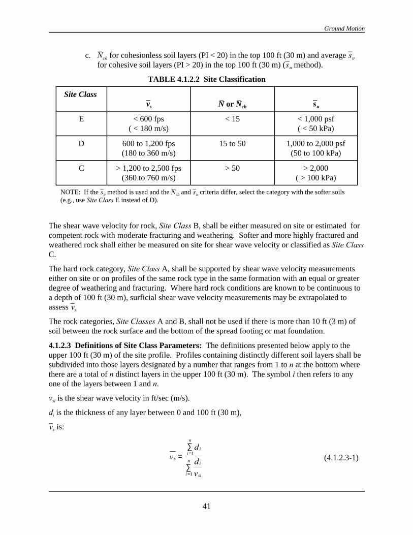
Ground Motion
41
c. Nch for cohesionless soil layers (PI < 20) in the top 100 ft (30 m) and average su
for cohesive soil layers (PI > 20) in the top 100 ft (30 m) (su method).
TABLE 4.1.2.2 Site Classification
Site Class vs N or Nch su
E < 600 fps( < 180 m/s)
< 15 < 1,000 psf( < 50 kPa)
D 600 to 1,200 fps(180 to 360 m/s)
15 to 50 1,000 to 2,000 psf(50 to 100 kPa)
C > 1,200 to 2,500 fps(360 to 760 m/s)
> 50 > 2,000( > 100 kPa)
NOTE: If the su method is used and the Nch and su criteria differ, select the category with the softer soils(e.g., use Site Class E instead of D).
The shear wave velocity for rock, Site Class B, shall be either measured on site or estimated forcompetent rock with moderate fracturing and weathering. Softer and more highly fractured andweathered rock shall either be measured on site for shear wave velocity or classified as Site ClassC.
The hard rock category, Site Class A, shall be supported by shear wave velocity measurementseither on site or on profiles of the same rock type in the same formation with an equal or greaterdegree of weathering and fracturing. Where hard rock conditions are known to be continuous toa depth of 100 ft (30 m), surficial shear wave velocity measurements may be extrapolated toassess vs.
The rock categories, Site Classes A and B, shall not be used if there is more than 10 ft (3 m) ofsoil between the rock surface and the bottom of the spread footing or mat foundation.
4.1.2.3 Definitions of Site Class Parameters: The definitions presented below apply to theupper 100 ft (30 m) of the site profile. Profiles containing distinctly different soil layers shall besubdivided into those layers designated by a number that ranges from 1 to n at the bottom wherethere are a total of n distinct layers in the upper 100 ft (30 m). The symbol i then refers to anyone of the layers between 1 and n.
vsi is the shear wave velocity in ft/sec (m/s).
di is the thickness of any layer between 0 and 100 ft (30 m),
vs is:
s
ii
n
i
sii
nv
d
d
v
=∑
∑
=
=
1
1
(4.1.2.3-1)
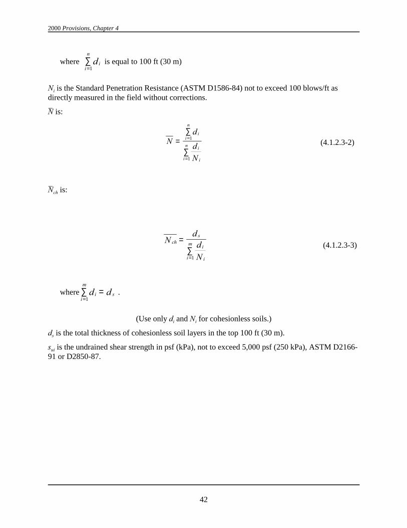
2000 Provisions, Chapter 4
42
where is equal to 100 ft (30 m)ii
n
d=∑
1
Ni is the Standard Penetration Resistance (ASTM D1586-84) not to exceed 100 blows/ft asdirectly measured in the field without corrections.
N is:
Nd
d
N
ii
n
i
ii
n=
∑
∑
=
=
1
1
(4.1.2.3-2)
Nch is:
chs
i
ii
mNdd
N
=∑=1
(4.1.2.3-3)
where .ii
m
sd d=∑ =
1
(Use only di and Ni for cohesionless soils.)
ds is the total thickness of cohesionless soil layers in the top 100 ft (30 m).
sui is the undrained shear strength in psf (kPa), not to exceed 5,000 psf (250 kPa), ASTM D2166-91 or D2850-87.

Ground Motion
43
su is:
uc
i
uii
ksdd
s
=∑=1
(4.1.2.3-4)
where .ii
k
cd d=∑ =
1
dc is the total thickness (100 - ds) of cohesive soil layers in the top 100 ft (30 m).
PI is the plasticity index, ASTM D4318-93.
w is the moisture content in percent, ASTM D2216-92.
4.1.2.4 Site Coefficients and Adjusted Maximum Considered Earthquake SpectralResponse Acceleration Parameters: The maximum considered earthquake spectral responseacceleration for short periods, SMS, and at 1 second, SM1, adjusted for site class effects, shall bedetermined by Eq. 4.1.2.4-1 and 4.1.2.4-2, respectively:
MS a sS F S= (4.1.2.4-1)
and
M vS F S1 1= (4.1.2.4-2)
where site coefficients Fa and Fv are defined in Tables 4.1.2.4a and b, respectively.
TABLE 4.1.2.4a Values of Fa as a Function of Site Class and Mapped Short-Period Maximum Considered Earthquake Spectral Acceleration
Site Class Mapped Maximum Considered Earthquake Spectral ResponseAcceleration at Short Periods
SS #### 0.25 SS = 0.50 SS = 0.75 SS = 1.00 SS $$$$ 1.25
A 0.8 0.8 0.8 0.8 0.8
B 1.0 1.0 1.0 1.0 1.0
C 1.2 1.2 1.1 1.0 1.0
D 1.6 1.4 1.2 1.1 1.0
E 2.5 1.7 1.2 0.9 0.9
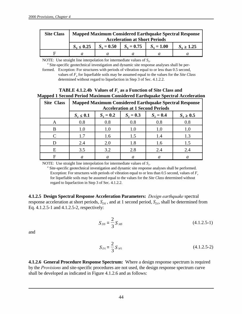
2000 Provisions, Chapter 4
Site Class Mapped Maximum Considered Earthquake Spectral ResponseAcceleration at Short Periods
SS #### 0.25 SS = 0.50 SS = 0.75 SS = 1.00 SS $$$$ 1.25
44
F a a a a aNOTE: Use straight line interpolation for intermediate values of SS. a Site-specific geotechnical investigation and dynamic site response analyses shall be per-formed. Exception: For structures with periods of vibration equal to or less than 0.5 second,
values of Fa for liquefiable soils may be assumed equal to the values for the Site Classdetermined without regard to liquefaction in Step 3 of Sec. 4.1.2.2.
TABLE 4.1.2.4b Values of Fv as a Function of Site Class and Mapped 1 Second Period Maximum Considered Earthquake Spectral Acceleration
Site Class Mapped Maximum Considered Earthquake Spectral ResponseAcceleration at 1 Second Periods
S1 #### 0.1 S1 = 0.2 S1 = 0.3 S1 = 0.4 S1 $$$$ 0.5
A 0.8 0.8 0.8 0.8 0.8
B 1.0 1.0 1.0 1.0 1.0
C 1.7 1.6 1.5 1.4 1.3
D 2.4 2.0 1.8 1.6 1.5
E 3.5 3.2 2.8 2.4 2.4
F a a a a aNOTE: Use straight line interpolation for intermediate values of S1. a Site-specific geotechnical investigation and dynamic site response analyses shall be performed.
Exception: For structures with periods of vibration equal to or less than 0.5 second, values of Fv
for liquefiable soils may be assumed equal to the values for the Site Class determined withoutregard to liquefaction in Step 3 of Sec. 4.1.2.2.
4.1.2.5 Design Spectral Response Acceleration Parameters: Design earthquake spectralresponse acceleration at short periods, SDS , and at 1 second period, SD1, shall be determined fromEq. 4.1.2.5-1 and 4.1.2.5-2, respectively:
DS MSS S=2
3(4.1.2.5-1)
and
D MS S1 1
2
3= (4.1.2.5-2)
4.1.2.6 General Procedure Response Spectrum: Where a design response spectrum is requiredby the Provisions and site-specific procedures are not used, the design response spectrum curveshall be developed as indicated in Figure 4.1.2.6 and as follows:
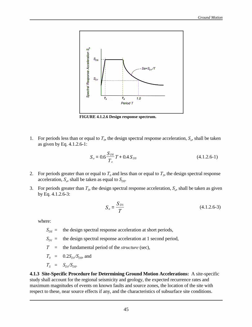
Ground Motion
45
FIGURE 4.1.2.6 Design response spectrum.
1. For periods less than or equal to T0, the design spectral response acceleration, Sa, shall be takenas given by Eq. 4.1.2.6-1:
aDS
oDSS
S
TT S= +0 6 0 4. . (4.1.2.6-1)
2. For periods greater than or equal to T0 and less than or equal to TS, the design spectral responseacceleration, Sa, shall be taken as equal to SDS.
3. For periods greater than TS, the design spectral response acceleration, Sa, shall be taken as givenby Eq. 4.1.2.6-3:
aD
SS
T= 1
(4.1.2.6-3)
where:
SDS = the design spectral response acceleration at short periods,
SD1 = the design spectral response acceleration at 1 second period,
T = the fundamental period of the structure (sec),
T0 = 0.2SD1/SDS, and
TS = SD1/SDS.
4.1.3 Site-Specific Procedure for Determining Ground Motion Accelerations: A site-specificstudy shall account for the regional seismicity and geology, the expected recurrence rates andmaximum magnitudes of events on known faults and source zones, the location of the site withrespect to these, near source effects if any, and the characteristics of subsurface site conditions.
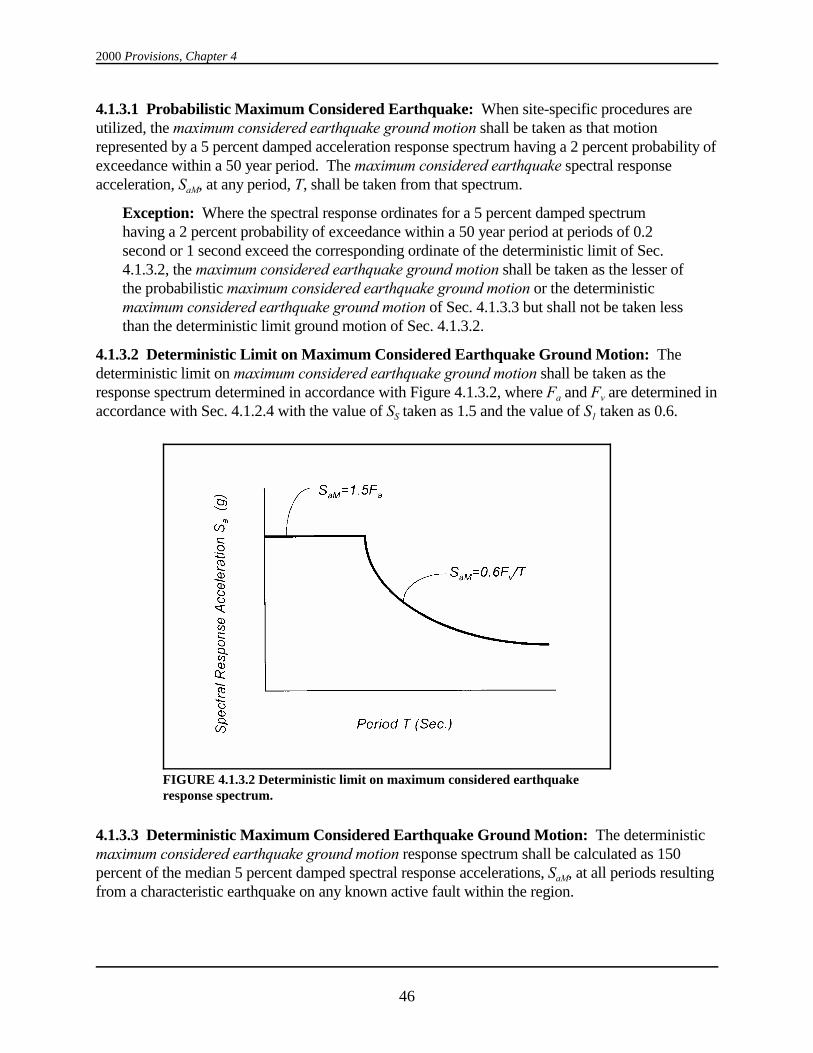
2000 Provisions, Chapter 4
46
FIGURE 4.1.3.2 Deterministic limit on maximum considered earthquakeresponse spectrum.
4.1.3.1 Probabilistic Maximum Considered Earthquake: When site-specific procedures areutilized, the maximum considered earthquake ground motion shall be taken as that motionrepresented by a 5 percent damped acceleration response spectrum having a 2 percent probability ofexceedance within a 50 year period. The maximum considered earthquake spectral responseacceleration, SaM, at any period, T, shall be taken from that spectrum.
Exception: Where the spectral response ordinates for a 5 percent damped spectrumhaving a 2 percent probability of exceedance within a 50 year period at periods of 0.2second or 1 second exceed the corresponding ordinate of the deterministic limit of Sec.4.1.3.2, the maximum considered earthquake ground motion shall be taken as the lesser ofthe probabilistic maximum considered earthquake ground motion or the deterministicmaximum considered earthquake ground motion of Sec. 4.1.3.3 but shall not be taken lessthan the deterministic limit ground motion of Sec. 4.1.3.2.
4.1.3.2 Deterministic Limit on Maximum Considered Earthquake Ground Motion: Thedeterministic limit on maximum considered earthquake ground motion shall be taken as theresponse spectrum determined in accordance with Figure 4.1.3.2, where Fa and Fv are determined inaccordance with Sec. 4.1.2.4 with the value of SS taken as 1.5 and the value of S1 taken as 0.6.
4.1.3.3 Deterministic Maximum Considered Earthquake Ground Motion: The deterministicmaximum considered earthquake ground motion response spectrum shall be calculated as 150percent of the median 5 percent damped spectral response accelerations, SaM, at all periods resultingfrom a characteristic earthquake on any known active fault within the region.
Ground Motion
47
4.1.3.5 Site-Specific Design Ground Motion: Where site-specific procedures are used todetermine the maximum considered earthquake ground motion response spectrum, the designspectral response acceleration at any period shall be determined from Eq. 4.1.3.5:
a aMS S=2
3(4.1.3.5)
and shall be greater than or equal to 80 percent of the Sa determined by the general responsespectrum in Sec. 4.1.2.6.
4.2 SEISMIC DESIGN CATEGORY: Each structure shall be assigned a Seismic DesignCategory in accordance with Sec. 4.2.1. Seismic Design Categories are used in the Provisions todetermine permissible structural systems, limitations on height and irregularity, those componentsof the structure that must be designed for seismic resistance, and the types of lateral force analysisthat must be performed.
4.2.1 Determination of Seismic Design Category: All structures shall be assigned to a SeismicDesign Category based on their Seismic Use Group and the design spectral response accelerationcoefficients, SDS and SD1, determined in accordance with Sec. 4.1.2.5. Each building and structureshall be assigned to the most severe Seismic Design Category in accordance with Table 4.2.1a or4.2.1b, irrespective of the fundamental period of vibration of the structure, T.
TABLE 4.2.1a Seismic Design Category Based on Short Period Response Accelerations
Value of SDS Seismic Use Group
I II III
SDS < 0.167 A A A
0.167 # SDS < 0.33 B B C
0.33 # SDS < 0.50 C C D
0.50 # SDS D a D a D a
a Seismic Use Group I and II structures located on sites with mapped maximum considered earthquake spectralresponse acceleration at 1 second period, S1, equal to or greater than 0.75 shall be assigned to Seismic DesignCategory E and Seismic Use Group III structures located on such sites shall be assigned to Seismic DesignCategory F.
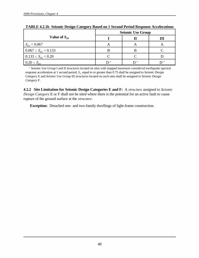
2000 Provisions, Chapter 4
48
TABLE 4.2.1b Seismic Design Category Based on 1 Second Period Response Accelerations
Value of SD1
Seismic Use Group
I II III
SD1 < 0.067 A A A
0.067 # SD1 < 0.133 B B C
0.133 # SD1 < 0.20 C C D
0.20 # SD1 D a D a D a
a Seismic Use Group I and II structures located on sites with mapped maximum considered earthquake spectralresponse acceleration at 1 second period, S1, equal to or greater than 0.75 shall be assigned to Seismic DesignCategory E and Seismic Use Group III structures located on such sites shall be assigned to Seismic DesignCategory F.
4.2.2 Site Limitation for Seismic Design Categories E and F: A structure assigned to SeismicDesign Category E or F shall not be sited where there is the potential for an active fault to causerupture of the ground surface at the structure.
Exception: Detached one- and two-family dwellings of light-frame construction.
49
Chapter 5
STRUCTURAL DESIGN CRITERIA
5.1 REFERENCE DOCUMENT:
The following reference document shall be used for loads other than earthquake and forcombinations of loads as indicated in this chapter:
ASCE 7 Minimum Design Loads for Buildings and Other Structures, ASCE 7, 1998
5.2 DESIGN BASIS:
5.2.1 General: The seismic analysis and design procedures to be used in the design of buildingsand other structures and their components shall be as prescribed in this chapter.
The structure shall include complete lateral- and vertical-force-resisting systems capable ofproviding adequate strength, stiffness, and energy dissipation capacity to withstand the designground motions within the prescribed limits of deformation and strength demand. The designground motions shall be assumed to occur along any direction of the structure. The adequacy ofthe structural systems shall be demonstrated through construction of a mathematical model andevaluation of this model for the effects of the design ground motions. Unless otherwise required,this evaluation shall consist of a linear elastic analysis in which design seismic forces aredistributed and applied throughout the height of the structure in accordance with the proceduresin Sec. 5.3 or Sec. 5.4. The corresponding structural deformations and internal forces in allmembers of the structure shall be determined and evaluated against acceptance criteria containedin the Provisions. Approved alternative procedure based on general principles of engineeringmechanics and dynamics are permitted to be used to establish the seismic forces and theirdistribution. If an alternative procedure is used, the corresponding internal forces and de-formations in the members shall be determined using a model consistent with the procedureadopted.
Individual members shall be provided with adequate strength to resist the shears, axial forces,and moments determined in accordance with the Provisions, and connections shall develop thestrength of the connected members or the forces indicated above. The deformation of thestructure shall not exceed the prescribed limits.
A continuous load path, or paths, with adequate strength and stiffness shall be provided totransfer all forces from the point of application to the final point of resistance. The foundationshall be designed to accommodate the forces developed or the movements imparted to thestructure by the design ground motions. In the determination of the foundation design criteria,special recognition shall be given to the dynamic nature of the forces, the expected groundmotions, and the design basis for strength and energy dissipation capacity of the structure.
5.2.2 Basic Seismic-Force-Resisting Systems: The basic lateral and vertical seismic-force-resisting system shall conform to one of the types indicated in Table 5.2.2 subject to the
2000 Provisions, Chapter 5
50
limitations on height based on Seismic Design Category indicated in the table. Each type issubdivided by the types of vertical element used to resist lateral seismic forces. The appropriateresponse modification coefficient, R, system overstrength factor, S0, and deflection amplificationfactor, Cd, indicated in Table 5.2.2 shall be used in determining the base shear, element designforces, and design story drift as indicated in the Provisions.
Seismic-force-resisting systems that are not contained in Table 5.2.2 shall be permitted ifanalytical and test data are submitted that establish the dynamic characteristics and demonstratethe lateral force resistance and energy dissipation capacity to be equivalent to the structuralsystems listed in Table 5.2.2 for equivalent response modification coefficient, R, system o-verstrength coefficient, S0, and deflection amplification factor, Cd, values.
Special framing requirements are indicated in Sec. 5.2.6 and in Chapters 8, 9, 10, 11, and 12 forstructures assigned to the various Seismic Design Categories.
5.2.2.1 Dual System: For a dual system, the moment frame shall be capable of resisting at least25 percent of the design forces. The total seismic force resistance is to be provided by thecombination of the moment frame and the shear walls or braced frames in proportion to theirrigidities.
5.2.2.2 Combinations of Framing Systems: Different seismic-force-resisting systems arepermitted along the two orthogonal axes of the structure. Combinations of seismic-force-resisting systems shall comply with the requirements of this section.
5.2.2.2.1 R and SSSS0 Factors: The response modification coefficient, R, in the direction underconsideration at any story shall not exceed the lowest response modification factor, R, for theseismic-force-resisting system in the same direction considered above that story excludingpenthouses. For other than dual systems where a combination of different structural systems isutilized to resist lateral forces in the same direction, the value of R used in that direction shall notbe greater than the least value of any of the systems utilized in the same direction. If a systemother than a dual system with a response modification coefficient, R, with a value of less than 5 isused as part of the seismic-force-resisting system in any direction of the structure, the lowestsuch value shall be used for the entire structure. The system overstrength factor, S0, in thedirection under consideration at any story shall not be less than the largest value of this factor forthe seismic-force-resisting system in the same direction considered above that story.
Exceptions:
1. Supported structural systems with a weight equal to or less than 10 percent of theweight of the structure.
2. Detached one- and two-family dwellings of light-frame construction.
5.2.2.2.2 Combination Framing Detailing Requirements: The detailing requirements of Sec. 5.2.6 required by the higher response modification coefficient, R, shall be used for structuralcomponents common to systems having different response modification coefficients.
5.2.2.3 Seismic Design Categories B and C: The structural framing system for structuresassigned to Seismic Design Categories B and C shall comply with the structure height andstructural limitations in Table 5.2.2.
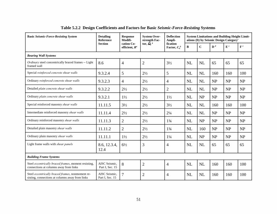
51
Table 5.2.2 Design Coefficients and Factors for Basic Seismic-Force-Resisting Systems
Basic Seismic-Force-Resisting System DetailingReferenceSection
ResponseModifi-cation Co-efficient, Ra
System Over-strength Fac-tor, SSSS0
g
DeflectionAmpli-ficationFactor, Cd
b
System Limitations and Building Height Limit-ations (ft) by Seismic Design Categoryc
B C D d E e F e
Bearing Wall Systems
Ordinary steel concentrically braced frames -- Lightframed wall
8.6 4 2 3½ NL NL 65 65 65
Special reinforced concrete shear walls 9.3.2.4 5 2½ 5 NL NL 160 160 100
Ordinary reinforced concrete shear walls 9.3.2.3 4 2½ 4 NL NL NP NP NP
Detailed plain concrete shear walls 9.3.2.2 2½ 2½ 2 NL NL NP NP NP
Ordinary plain concrete shear walls 9.3.2.1 1½ 2½ 1½ NL NP NP NP NP
Special reinforced masonry shear walls 11.11.5 3½ 2½ 3½ NL NL 160 160 100
Intermediate reinforced masonry shear walls 11.11.4 2½ 2½ 2¼ NL NL NP NP NP
Ordinary reinforced masonry shear walls 11.11.3 2 2½ 1¾ NL NP NP NP NP
Detailed plain masonry shear walls 11.11.2 2 2½ 1¾ NL 160 NP NP NP
Ordinary plain masonry shear walls 11.11.1 1½ 2½ 1¼ NL NP NP NP NP
Light frame walls with shear panels 8.6, 12.3.4,12.4
6½ 3 4 NL NL 65 65 65
Building Frame Systems
Steel eccentrically braced frames, moment resisting,connections at columns away from links
AISC Seismic, Part I, Sec. 15
8 2 4 NL NL 160 160 100
Steel eccentrically braced frames, nonmoment re-sisting, connections at columns away from links
AISC Seismic,Part I, Sec. 15
7 2 4 NL NL 160 160 100

Basic Seismic-Force-Resisting System DetailingReferenceSection
ResponseModifi-cation Co-efficient, Ra
System Over-strength Fac-tor, SSSS0
g
DeflectionAmpli-ficationFactor, Cd
b
System Limitations and Building Height Limit-ations (ft) by Seismic Design Categoryc
B C D d E e F e
52
Special steel concentrically braced frames AISC Seismic,Part I, Sec. 13
6 2 5 NL NL 160 160 100
Ordinary steel concentrically braced frames 8.4.4; AISCSeismic
5 2 4½ NL NL 35k 35k NPk
Special reinforced concrete shear walls 9.3.2.4 6 2½ 5 NL NL 160 160 100
Ordinary reinforced concrete shear walls 9.3.2.3 5 2½ 4½ NL NL NP NP NP
Detailed plain concrete shear walls 9.3.2.2 3 2½ 2½ NL NL NP NP NP
Ordinary plain concrete shear walls 9.3.2.1 2 2½ 2 NL NP NP NP NP
Composite eccentrically braced frames AISC Seismic,Part II, Sec. 14
8 2 4 NL NL 160 160 100
Composite concentrically braced frames AISC Seismic,Part II, Sec. 13
5 2 4½ NL NL 160 160 100
Ordinary composite braced frames AISC Seismic,Part II, Sec. 12
3 2 3 NL NL NP NP NP
Composite steel plate shear walls AISC Seismic,Part II, Sec. 17
6½ 2½ 5½ NL NL 160 160 100
Special composite reinforced concrete shear wallswith steel elements
AISC Seismic,Part II, Sec. 16
6 2½ 5 NL NL 160 160 100
Ordinary composite reinforced concrete shear wallswith steel elements
AISC Seismic.Part II, Sec. 15
5 2½ 4½ NL NL NP NP NP
Special reinforced masonry shear walls 11.11.5 4½ 2½ 4 NL NL 160 160 100
Intermediate reinforced masonry shear walls 11.11.4 3 2½ 2½ NL NL NP NP NP
Ordinary reinforced masonry shear walls 11.11.3 2½ 2½ 2¼ NL NP NP NP NP
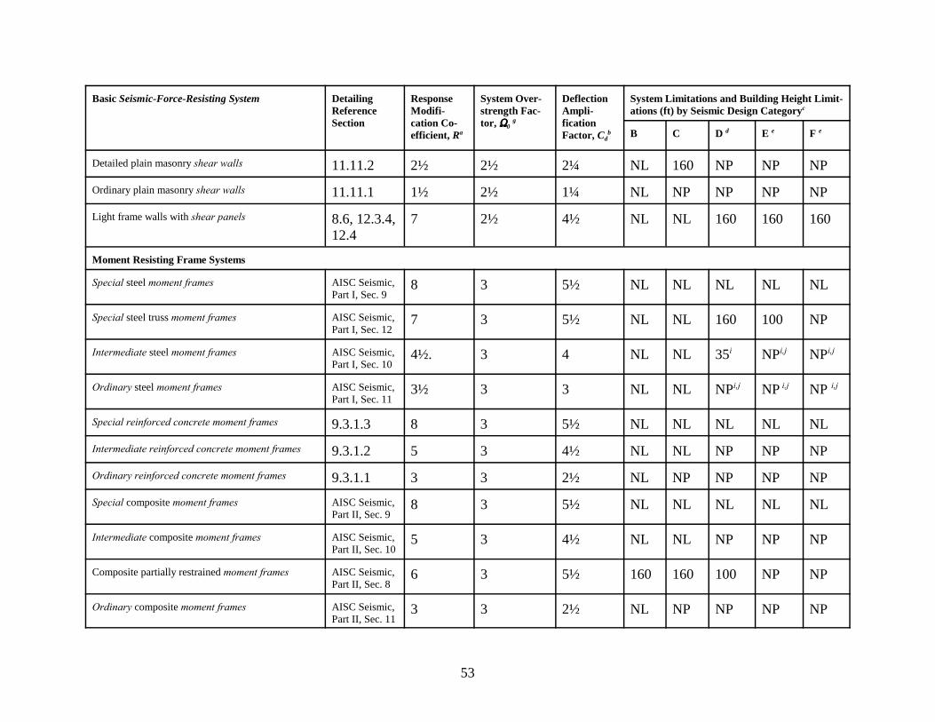
Basic Seismic-Force-Resisting System DetailingReferenceSection
ResponseModifi-cation Co-efficient, Ra
System Over-strength Fac-tor, SSSS0
g
DeflectionAmpli-ficationFactor, Cd
b
System Limitations and Building Height Limit-ations (ft) by Seismic Design Categoryc
B C D d E e F e
53
Detailed plain masonry shear walls 11.11.2 2½ 2½ 2¼ NL 160 NP NP NP
Ordinary plain masonry shear walls 11.11.1 1½ 2½ 1¼ NL NP NP NP NP
Light frame walls with shear panels 8.6, 12.3.4,12.4
7 2½ 4½ NL NL 160 160 160
Moment Resisting Frame Systems
Special steel moment frames AISC Seismic,Part I, Sec. 9
8 3 5½ NL NL NL NL NL
Special steel truss moment frames AISC Seismic,Part I, Sec. 12
7 3 5½ NL NL 160 100 NP
Intermediate steel moment frames AISC Seismic, Part I, Sec. 10
4½. 3 4 NL NL 35i NPi,j NPi,j
Ordinary steel moment frames AISC Seismic,Part I, Sec. 11
3½ 3 3 NL NL NPi,j NP i,j NP i,j
Special reinforced concrete moment frames 9.3.1.3 8 3 5½ NL NL NL NL NL
Intermediate reinforced concrete moment frames 9.3.1.2 5 3 4½ NL NL NP NP NP
Ordinary reinforced concrete moment frames 9.3.1.1 3 3 2½ NL NP NP NP NP
Special composite moment frames AISC Seismic,Part II, Sec. 9
8 3 5½ NL NL NL NL NL
Intermediate composite moment frames AISC Seismic,Part II, Sec. 10
5 3 4½ NL NL NP NP NP
Composite partially restrained moment frames AISC Seismic,Part II, Sec. 8
6 3 5½ 160 160 100 NP NP
Ordinary composite moment frames AISC Seismic,Part II, Sec. 11
3 3 2½ NL NP NP NP NP
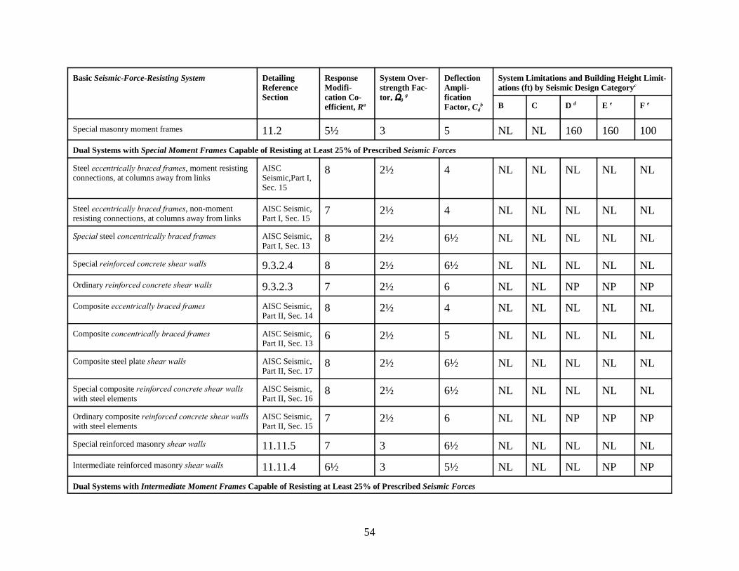
Basic Seismic-Force-Resisting System DetailingReferenceSection
ResponseModifi-cation Co-efficient, Ra
System Over-strength Fac-tor, SSSS0
g
DeflectionAmpli-ficationFactor, Cd
b
System Limitations and Building Height Limit-ations (ft) by Seismic Design Categoryc
B C D d E e F e
54
Special masonry moment frames 11.2 5½ 3 5 NL NL 160 160 100
Dual Systems with Special Moment Frames Capable of Resisting at Least 25% of Prescribed Seismic Forces
Steel eccentrically braced frames, moment resistingconnections, at columns away from links
AISCSeismic,Part I,Sec. 15
8 2½ 4 NL NL NL NL NL
Steel eccentrically braced frames, non-momentresisting connections, at columns away from links
AISC Seismic,Part I, Sec. 15
7 2½ 4 NL NL NL NL NL
Special steel concentrically braced frames AISC Seismic,Part I, Sec. 13
8 2½ 6½ NL NL NL NL NL
Special reinforced concrete shear walls 9.3.2.4 8 2½ 6½ NL NL NL NL NL
Ordinary reinforced concrete shear walls 9.3.2.3 7 2½ 6 NL NL NP NP NP
Composite eccentrically braced frames AISC Seismic,Part II, Sec. 14
8 2½ 4 NL NL NL NL NL
Composite concentrically braced frames AISC Seismic,Part II, Sec. 13
6 2½ 5 NL NL NL NL NL
Composite steel plate shear walls AISC Seismic,Part II, Sec. 17
8 2½ 6½ NL NL NL NL NL
Special composite reinforced concrete shear wallswith steel elements
AISC Seismic,Part II, Sec. 16
8 2½ 6½ NL NL NL NL NL
Ordinary composite reinforced concrete shear wallswith steel elements
AISC Seismic,Part II, Sec. 15
7 2½ 6 NL NL NP NP NP
Special reinforced masonry shear walls 11.11.5 7 3 6½ NL NL NL NL NL
Intermediate reinforced masonry shear walls 11.11.4 6½ 3 5½ NL NL NL NP NP
Dual Systems with Intermediate Moment Frames Capable of Resisting at Least 25% of Prescribed Seismic Forces

Basic Seismic-Force-Resisting System DetailingReferenceSection
ResponseModifi-cation Co-efficient, Ra
System Over-strength Fac-tor, SSSS0
g
DeflectionAmpli-ficationFactor, Cd
b
System Limitations and Building Height Limit-ations (ft) by Seismic Design Categoryc
B C D d E e F e
55
Special steel concentrically braced frames f AISC Seismic,Part I, Sec. 13
4½ 2½ 4 NL NL 35i NPi,j NPi,j
Special reinforced concrete shear walls 9.3.2.4 6 2½ 5 NL NL 160 100 100
Ordinary reinforced concrete shear walls 9.3.2.3 5½ 2½ 4½ NL NL NP NP NP
Ordinary reinforced masonry shear walls 11.11.3 3 3 2½ NL 160 NP NP NP
Intermediate reinforced masonry shear walls 11.11.4 5 3 4½ NL NL 160 NP NP
Composite concentrically braced frames AISC Seismic,Part II, Sec. 13
5 2½ 4½ NL NL 160 100 NP
Ordinary composite braced frames AISC Seismic,Part II, Sec. 12
4 2½ 3 NL NL NP NP NP
Ordinary composite reinforced concrete shear wallswith steel elements
AISC Seismic,Part II, Sec. 15
5½ 2½ 4½ NL NL NP NP NP
Inverted Pendulum Systems and Cantilevered Column Systems
Special steel moment frames AISC Seismic,Part I, Sec. 9
2½ 2 2½ NL NL NL NL NL
Ordinary steel moment frames AISC Seismic,Part I, Sec. 11
1¼ 2 2½ NL NL NP NP NP
Special reinforced concrete moment frames 9.3.1.3 2½ 2 1¼ NL NL NL NL NL
Structural Steel Systems Not Specifically Detailedfor Seismic Resistance
AISC-ASD,AISC-LRFD,AISI
3 3 3 NL NL NP NP NP

56
NOTES FOR TABLE 5.2.2a Response modification coefficient, R, for use throughout the Provisions.
b Deflection amplification factor, Cd, for use in Sec. 5.4.6.1 and 5.4.6.2.
c NL = not limited and NP = not permitted. If using metric units, 100 ft approximately equals 30m and 160 ft approximately equals 50 m. Heights are measured from the base of the structure asdefined in Sec. 2.1.
d See Sec. 5.2.2.4.1 for a description of building systems limited to buildings with a height of 240ft (70 m) or less.
e See Sec. 5.2.2.5 for building systems limited to buildings with a height of 160 ft (50 m) or less.
f An ordinary moment frame is permitted to be used in lieu of an Intermediate moment frame inSeismic Design Categories B and C.
g The tabulated value of the overstrength factor, S0, may be reduced by subtracting ½ forstructures with flexible diaphragms but shall not be taken as less than 2 for any structure.
i Steel ordinary moment frames and intermediate moment frames are permitted in single-storybuildings up to a height of 60 ft when the moment joints of field connections are constructed ofbolted end plates and the dead load of the roof does not exceed 15 psf.
j Steel ordinary moment frames are permitted in buildings up to a height of 35 ft where the deadload of the walls, floors, and roofs does not exceed 15 psf.
k Steel ordinary braced frames are permitted in single-story buildings up to a height of 60 ft whenthe dead load of the roof does not exceed 15 psf and in penthouse structures.
Structural Design Criteria
57
5.2.2.4 Seismic Design Categories D and E: The structural framing system for a structureassigned to Seismic Design Categories D and E shall comply with Sec. 5.2.2.3 and the additionalrequirements of this section.
5.2.2.4.1 Limited Building Height: The height limit in Table 5.2.2 is permitted to be increasedto 240 ft (70 m) in buildings that have steel braced frames or concrete cast-in-place shear walls. Such buildings shall be configured such that the braced frames or shear walls arranged in anyone plane conform to the following:
1. The braced frames or cast-in-place special reinforced concrete shear walls in any one planeshall resist no more than 60 percent of the total seismic forces in each direction, neglectingtorsional effects, and
2. The seismic force in any braced frame or shear wall resulting from torsional effects shall notexceed 20 percent of the total seismic force in that braced frame or shear wall.
5.2.2.4.2 Interaction Effects: Moment frames that are enclosed or adjoined by more rigidelements not considered to be part of the seismic-force-resisting system shall be designed so thatthe action or failure of those elements will not impair the vertical load and seismic-force-resistingcapability of the frame. The design shall consider and provide for the effect of these rigidelements on the structural system at structure deformations corresponding to the design storydrift, ), as determined in Sec. 5.4.6. In addition, the effects of these elements shall be consideredwhen determining whether a structure has one or more of the irregularities defined in Sec. 5.2.3.
5.2.2.4.3 Deformational Compatibility: Every structural component not included in theseismic-force-resisting system in the direction under consideration shall be designed to beadequate for the vertical load-carrying capacity and the induced moments and shears resultingfrom the design story drift, ), as determined in accordance with Sec. 5.4.6 (also see Sec. 5.2.7).
Exception: Beams and columns and their connections not designed as part of the lateral-force-resisting system but meeting the detailing requirements for either intermediatemoment frames or special moment frames are permitted to be designed to be adequate forthe vertical load-carrying capacity and the induced moments and shears resulting from thedeformation of the building under the application of the design seismic forces.
When determining the moments and shears induced in components that are not included in theseismic-force-resisting system in the direction under consideration, the stiffening effects ofadjoining rigid structural and nonstructural elements shall be considered and a rational value ofmember and restraint stiffness shall be used.
5.2.2.4.4 Special Moment Frames: A special moment frame that is used but not required byTable 5.2.2 is permitted to be discontinued and supported by a more rigid system with a lowerresponse modification coefficient, R, provided the requirements of Sec. 5.2.6.2.3 and 5.2.6.4.2are met. Where a special moment frame is required by Table 5.2.2, the frame shall be continuousto the foundation.
2000 Provisions, Chapter 5
58
5.2.2.5 Seismic Design Category F: The framing systems of buildings assigned to SeismicDesign Category F shall conform to the requirements of Sec. 5.2.2.4 for Seismic DesignCategories D and E and to the additional requirements and limitations of this section. The heightlimitation of Sec. 5.2.2.4.1 shall be reduced from 240 ft to 160 ft (70 to 50 m).
5.2.3 Structure Configuration: Structures shall be classified as regular or irregular based uponthe criteria in this section. Such classification shall be based on the plan and vertical configura-tion.
5.2.3.1 Diaphragm Flexibility: Diaphragms constructed of untopped steel decking, woodstructural panels, or similar panelized construction shall be considered flexible in structureshaving concrete or masonry shear walls. Diaphragms constructed of wood structural panelsshall be considered rigid in light-frame structures using structural panels for lateral loadresistance. Diaphragms of other types shall be considered flexible when the maximum lateraldeformation of the diaphragm is more than two times the average story drift of the associatedstory. The loadings used for this calculation shall be those prescribed by Sec. 5.4
5.2.3.2 Plan Irregularity: Structures having one or more of the features listed in Table 5.2.3.2shall be designated as having plan structural irregularity and shall comply with the requirementsin the sections referenced in Table 5.2.3.2.
5.2.3.3 Vertical Irregularity: Structures having one or more of the features listed in Table5.2.3.3 shall be designated as having vertical irregularity and shall comply with the requirementsin the sections referenced in Table 5.2.3.3.
Exceptions:
1. Structural irregularities of Types 1a, 1b, or 2 in Table 5.2.3.3 do not apply where nostory drift ratio under design lateral load is greater than 130 percent of the story driftratio of the story immediately above. Torsional effects need not be considered in thecalculation of story drifts for the purpose of this determination. The story drift ratiorelationship for the top two stories of the structure are not required to be evaluated.
2. Irregularities Types 1a, 1b, and 2 of Table 5.2.3.3 are not required to be consideredfor one-story structures or for two-story structures in Seismic Design Categories A,B, C, or D.

Structural Design Criteria
59
TABLE 5.2.3.2 Plan Structural Irregularities
Irregularity Type and Description ReferenceSection
Seismic Design
Category Application
1a Torsional Irregularity – to be considered when dia-phragms are not flexibleTorsional irregularity shall be considered to exist whenthe maximum story drift, computed including accidentaltorsion, at one end of the structure transverse to an axis ismore than 1.2 times the average of the story drifts at thetwo ends of the structure.
5.2.6.4.2
5.4.4
D, E, and F
C, D, E, and F
1b Extreme Torsional Irregularity -- to be consideredwhen diaphragms are not flexibleExtreme torsional irregularity shall be considered to existwhen the maximum story drift, computed includingaccidental torsion, at one end of the structure transverseto an axis is more than 1.4 times the average of the storydrifts at the two ends of the structure.
5.2.6.4.2
5.4.4
5.2.6.5.1
D, E, and F
C, D, E, and F
E and F
2 Re-entrant Corners Plan configurations of a structure and its lateral-force-re-sisting system contain re-entrant corners where bothprojections of the structure beyond a re-entrant corner aregreater than 15 percent of the plan dimension of thestructure in the given direction.
5.2.6.4.2 D, E, and F
3 Diaphragm Discontinuity Diaphragms with abrupt discontinuities or variations instiffness including those having cutout or open areasgreater than 50 percent of the gross enclosed diaphragmarea or changes in effective diaphragm stiffness of morethan 50 percent from one story to the next.
5.2.6.4.2 D, E, and F
4 Out-of-Plane OffsetsDiscontinuities in a lateral force resistance path such asout-of-plane offsets of the vertical elements.
5.2.6.4.2
5.2.6.2.10
D, E, and F
B, C, D, E, andF
5 Nonparallel Systems The vertical lateral-force-resisting elements are notparallel to or symmetric about the major orthogonal axesof the lateral-force-resisting system.
5.2.5.2 C, D, E, and F
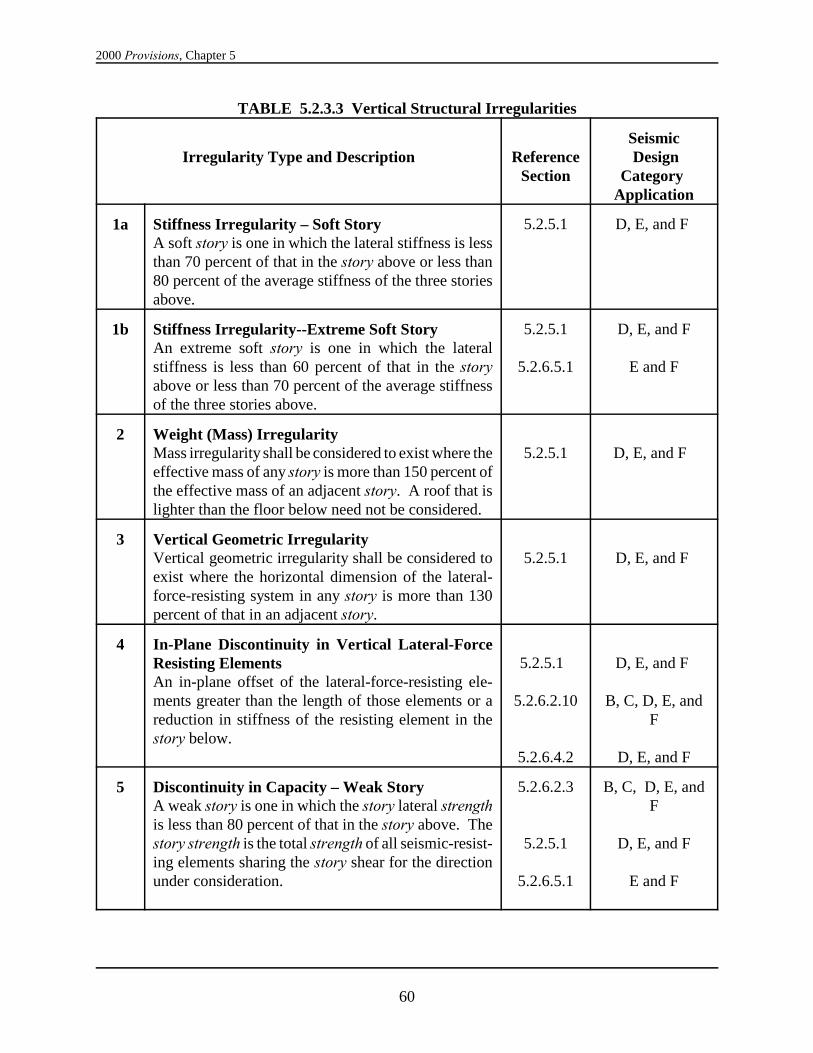
2000 Provisions, Chapter 5
60
TABLE 5.2.3.3 Vertical Structural Irregularities
Irregularity Type and Description ReferenceSection
Seismic Design
Category Application
1a Stiffness Irregularity – Soft Story A soft story is one in which the lateral stiffness is lessthan 70 percent of that in the story above or less than80 percent of the average stiffness of the three storiesabove.
5.2.5.1 D, E, and F
1b Stiffness Irregularity--Extreme Soft StoryAn extreme soft story is one in which the lateralstiffness is less than 60 percent of that in the storyabove or less than 70 percent of the average stiffnessof the three stories above.
5.2.5.1
5.2.6.5.1
D, E, and F
E and F
2 Weight (Mass) Irregularity Mass irregularity shall be considered to exist where theeffective mass of any story is more than 150 percent ofthe effective mass of an adjacent story. A roof that islighter than the floor below need not be considered.
5.2.5.1 D, E, and F
3 Vertical Geometric Irregularity Vertical geometric irregularity shall be considered toexist where the horizontal dimension of the lateral-force-resisting system in any story is more than 130percent of that in an adjacent story.
5.2.5.1 D, E, and F
4 In-Plane Discontinuity in Vertical Lateral-ForceResisting ElementsAn in-plane offset of the lateral-force-resisting ele-ments greater than the length of those elements or areduction in stiffness of the resisting element in thestory below.
5.2.5.1
5.2.6.2.10
5.2.6.4.2
D, E, and F
B, C, D, E, andF
D, E, and F
5 Discontinuity in Capacity – Weak StoryA weak story is one in which the story lateral strengthis less than 80 percent of that in the story above. Thestory strength is the total strength of all seismic-resist-ing elements sharing the story shear for the directionunder consideration.
5.2.6.2.3
5.2.5.1
5.2.6.5.1
B, C, D, E, andF
D, E, and F
E and F
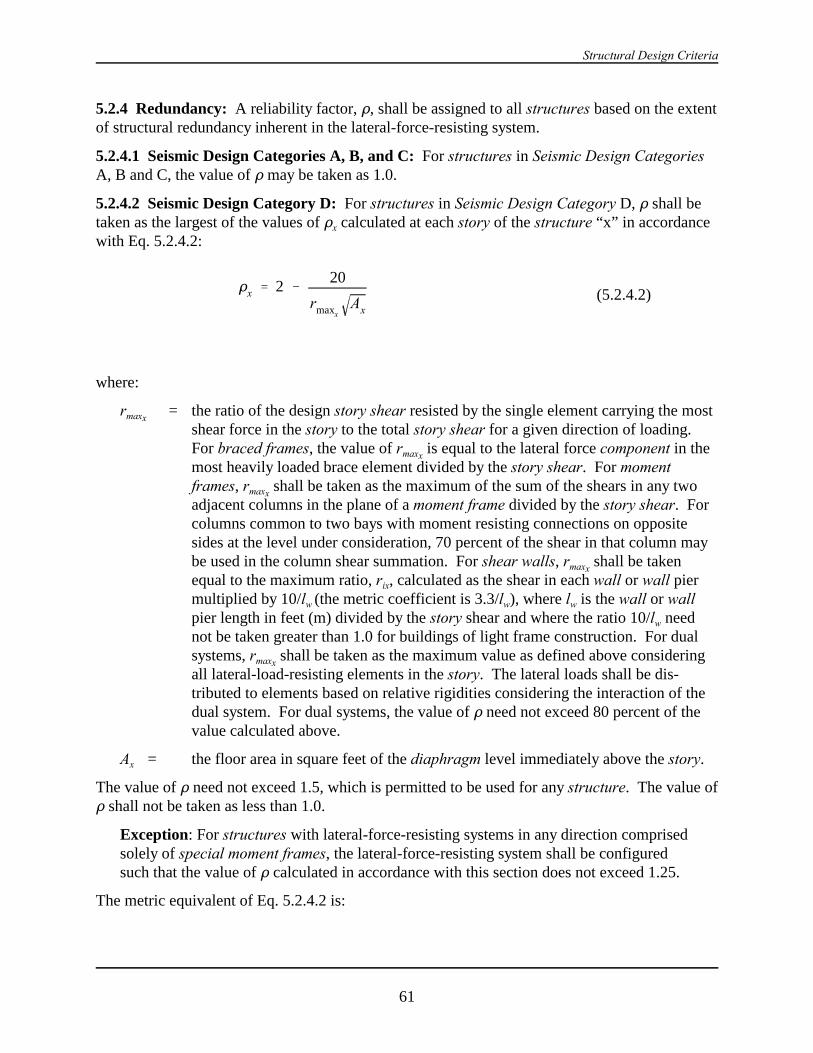
Structural Design Criteria
61
Dx ' 2 &20
rmaxxAx
(5.2.4.2)
5.2.4 Redundancy: A reliability factor, D, shall be assigned to all structures based on the extentof structural redundancy inherent in the lateral-force-resisting system.
5.2.4.1 Seismic Design Categories A, B, and C: For structures in Seismic Design CategoriesA, B and C, the value of D may be taken as 1.0.
5.2.4.2 Seismic Design Category D: For structures in Seismic Design Category D, D shall betaken as the largest of the values of Dx calculated at each story of the structure “x” in accordancewith Eq. 5.2.4.2:
where:
rmaxx= the ratio of the design story shear resisted by the single element carrying the most
shear force in the story to the total story shear for a given direction of loading. For braced frames, the value of rmaxx
is equal to the lateral force component in themost heavily loaded brace element divided by the story shear. For momentframes, rmaxx
shall be taken as the maximum of the sum of the shears in any twoadjacent columns in the plane of a moment frame divided by the story shear. Forcolumns common to two bays with moment resisting connections on oppositesides at the level under consideration, 70 percent of the shear in that column maybe used in the column shear summation. For shear walls, rmaxx
shall be takenequal to the maximum ratio, rix, calculated as the shear in each wall or wall piermultiplied by 10/lw (the metric coefficient is 3.3/lw), where lw is the wall or wallpier length in feet (m) divided by the story shear and where the ratio 10/lw neednot be taken greater than 1.0 for buildings of light frame construction. For dualsystems, rmaxx
shall be taken as the maximum value as defined above consideringall lateral-load-resisting elements in the story. The lateral loads shall be dis-tributed to elements based on relative rigidities considering the interaction of thedual system. For dual systems, the value of D need not exceed 80 percent of thevalue calculated above.
Ax = the floor area in square feet of the diaphragm level immediately above the story.
The value of D need not exceed 1.5, which is permitted to be used for any structure. The value ofD shall not be taken as less than 1.0.
Exception: For structures with lateral-force-resisting systems in any direction comprisedsolely of special moment frames, the lateral-force-resisting system shall be configuredsuch that the value of D calculated in accordance with this section does not exceed 1.25.
The metric equivalent of Eq. 5.2.4.2 is:

2000 Provisions, Chapter 5
62
Dx ' 2 &6.1
rmaxxAx
where Ax is in square meters.
5.2.4.3 Seismic Design Categories E and F: For structures in Seismic Design Categories Eand F, the value of D shall be calculated as indicated in Section 5.2.4.2, above.
Exception: For structures with lateral-force-resisting systems in any direction comprisedsolely of special moment frames, the lateral-force-resisting system shall be configuredsuch that the value of D calculated in accordance with Sec. 5.2.4.2 does not exceed 1.1.
5.2.5 Structural Analysis: A structural analysis conforming to one of the types permitted inSection 5.2.5.1 shall be made for all structures. Application of loading shall be as indicated inSec. 5.2.5.2 and as required by the selected analysis procedure. All members of the structure’sseismic-force-resisting system and their connections shall have adequate strength to resist theforces, QE, predicted by the analysis in combination with other loads as required by Sec. 5.2.7. Drifts predicted by the analysis shall be within the limits specified by Sec. 5.2.8. If a nonlinearanalysis is performed, component deformation demands shall not exceed limiting values asindicated in Sec. 5.7.3.2.
Exception: For structures in Seismic Design Category A, drift need not be evaluated.
5.2.5.1 Analysis Procedures: The structural analysis required by Sec. 5.2.5 shall consist of oneof the types permitted in Table 5.2.5.1 based on the structure’s Seismic Design Category,structural system, dynamic properties, and regularity or, with the approval of the authority havingjurisdiction, an alternative generally accepted procedure shall be permitted to be used.
5.2.5.2 Application of Loading: The directions of application of seismic forces used in thedesign shall be those that will produce the most critical load effects. It shall be permitted tosatisfy this requirement using the procedures of Sec. 5.2.5.2.1 for Seismic Design Category A orB, Sec. 5.2.5.2.2 for Seismic Design Category C, and Sec. 5.2.5.2.3 for Seismic Design CategoryD, E, or F.
5.2.5.2.1 Seismic Design Category A or B: For structures assigned to Seismic DesignCategory A or B, the design seismic forces are permitted to be applied separately in each of twoorthogonal directions and orthogonal interaction effects may be neglected.

63
TABLE 5.2.5.1 Permitted Analytical Procedures
SeismicDesignCategory Structural Characteristics
Index ForceAnalysis,Sec. 5.3
EquivalentLateralForce Anal-ysis, Sec.5.4
Modal Re-sponseSpectrumAnalysis,Sec. 5.5
LinearResponseHistoryAnalysis,Sec. 5.6
NonlinearResponseHistoryAnalysis,Sec. 5.7
A Regular or irregular P P P P P
B, C Regular or irregular NP P P P P
D, E, F Regular structures with T < 3.5Ts
and all structures of light frameconstruction
NP P P P P
Irregular structures with T < 3.5Ts
and having only plan irregularitiesType 2, 3, 4, or 5 Table 5.2.3.2 orvertical irregularities Type 4 or 5 ofTable 5.2.3.3.
NP P P P P
Irregular structures with T < 3.5Ts
and having either plan irregularitiesType 1a or 1b of Table 5.2.3.2 orvertical irregularities Type 1a or1b, 2, or 3 of Table 5.2.3.3.
NP NP P P P
All other structures NP NP P P P
Notes: P indicates permitted; NP indicates not permitted.
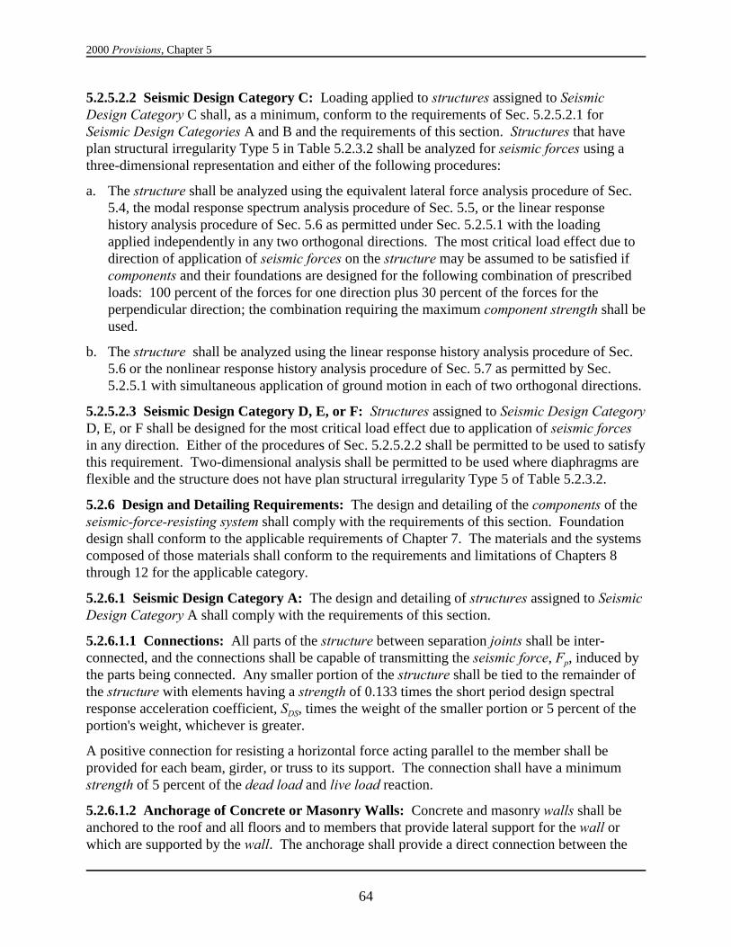
2000 Provisions, Chapter 5
64
5.2.5.2.2 Seismic Design Category C: Loading applied to structures assigned to SeismicDesign Category C shall, as a minimum, conform to the requirements of Sec. 5.2.5.2.1 forSeismic Design Categories A and B and the requirements of this section. Structures that haveplan structural irregularity Type 5 in Table 5.2.3.2 shall be analyzed for seismic forces using athree-dimensional representation and either of the following procedures:
a. The structure shall be analyzed using the equivalent lateral force analysis procedure of Sec.5.4, the modal response spectrum analysis procedure of Sec. 5.5, or the linear responsehistory analysis procedure of Sec. 5.6 as permitted under Sec. 5.2.5.1 with the loadingapplied independently in any two orthogonal directions. The most critical load effect due todirection of application of seismic forces on the structure may be assumed to be satisfied ifcomponents and their foundations are designed for the following combination of prescribedloads: 100 percent of the forces for one direction plus 30 percent of the forces for theperpendicular direction; the combination requiring the maximum component strength shall beused.
b. The structure shall be analyzed using the linear response history analysis procedure of Sec.5.6 or the nonlinear response history analysis procedure of Sec. 5.7 as permitted by Sec.5.2.5.1 with simultaneous application of ground motion in each of two orthogonal directions.
5.2.5.2.3 Seismic Design Category D, E, or F: Structures assigned to Seismic Design CategoryD, E, or F shall be designed for the most critical load effect due to application of seismic forcesin any direction. Either of the procedures of Sec. 5.2.5.2.2 shall be permitted to be used to satisfythis requirement. Two-dimensional analysis shall be permitted to be used where diaphragms areflexible and the structure does not have plan structural irregularity Type 5 of Table 5.2.3.2.
5.2.6 Design and Detailing Requirements: The design and detailing of the components of theseismic-force-resisting system shall comply with the requirements of this section. Foundationdesign shall conform to the applicable requirements of Chapter 7. The materials and the systemscomposed of those materials shall conform to the requirements and limitations of Chapters 8through 12 for the applicable category.
5.2.6.1 Seismic Design Category A: The design and detailing of structures assigned to SeismicDesign Category A shall comply with the requirements of this section.
5.2.6.1.1 Connections: All parts of the structure between separation joints shall be inter-connected, and the connections shall be capable of transmitting the seismic force, Fp, induced bythe parts being connected. Any smaller portion of the structure shall be tied to the remainder ofthe structure with elements having a strength of 0.133 times the short period design spectralresponse acceleration coefficient, SDS, times the weight of the smaller portion or 5 percent of theportion's weight, whichever is greater.
A positive connection for resisting a horizontal force acting parallel to the member shall beprovided for each beam, girder, or truss to its support. The connection shall have a minimumstrength of 5 percent of the dead load and live load reaction.
5.2.6.1.2 Anchorage of Concrete or Masonry Walls: Concrete and masonry walls shall beanchored to the roof and all floors and to members that provide lateral support for the wall orwhich are supported by the wall. The anchorage shall provide a direct connection between the
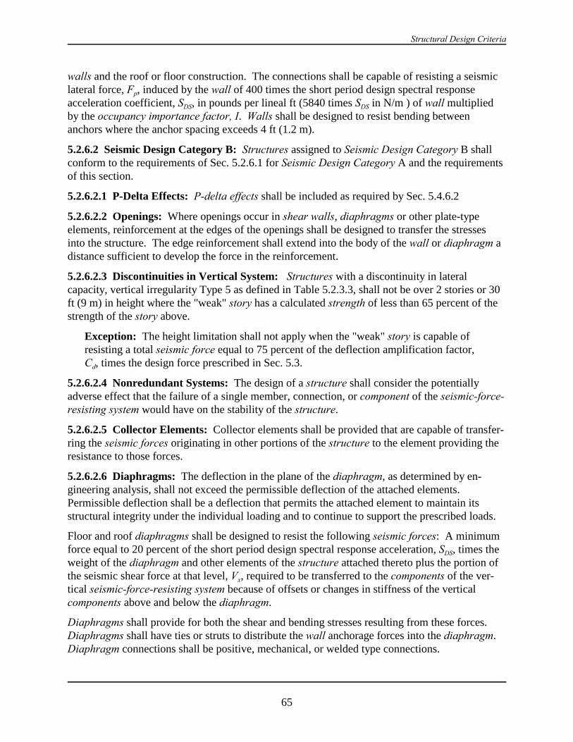
Structural Design Criteria
65
walls and the roof or floor construction. The connections shall be capable of resisting a seismiclateral force, Fp, induced by the wall of 400 times the short period design spectral responseacceleration coefficient, SDS, in pounds per lineal ft (5840 times SDS in N/m ) of wall multipliedby the occupancy importance factor, I. Walls shall be designed to resist bending betweenanchors where the anchor spacing exceeds 4 ft (1.2 m).
5.2.6.2 Seismic Design Category B: Structures assigned to Seismic Design Category B shallconform to the requirements of Sec. 5.2.6.1 for Seismic Design Category A and the requirementsof this section.
5.2.6.2.1 P-Delta Effects: P-delta effects shall be included as required by Sec. 5.4.6.2
5.2.6.2.2 Openings: Where openings occur in shear walls, diaphragms or other plate-typeelements, reinforcement at the edges of the openings shall be designed to transfer the stressesinto the structure. The edge reinforcement shall extend into the body of the wall or diaphragm adistance sufficient to develop the force in the reinforcement.
5.2.6.2.3 Discontinuities in Vertical System: Structures with a discontinuity in lateralcapacity, vertical irregularity Type 5 as defined in Table 5.2.3.3, shall not be over 2 stories or 30ft (9 m) in height where the "weak" story has a calculated strength of less than 65 percent of thestrength of the story above.
Exception: The height limitation shall not apply when the "weak" story is capable ofresisting a total seismic force equal to 75 percent of the deflection amplification factor,Cd, times the design force prescribed in Sec. 5.3.
5.2.6.2.4 Nonredundant Systems: The design of a structure shall consider the potentiallyadverse effect that the failure of a single member, connection, or component of the seismic-force-resisting system would have on the stability of the structure.
5.2.6.2.5 Collector Elements: Collector elements shall be provided that are capable of transfer-ring the seismic forces originating in other portions of the structure to the element providing theresistance to those forces.
5.2.6.2.6 Diaphragms: The deflection in the plane of the diaphragm, as determined by en-gineering analysis, shall not exceed the permissible deflection of the attached elements. Permissible deflection shall be a deflection that permits the attached element to maintain itsstructural integrity under the individual loading and to continue to support the prescribed loads.
Floor and roof diaphragms shall be designed to resist the following seismic forces: A minimumforce equal to 20 percent of the short period design spectral response acceleration, SDS, times theweight of the diaphragm and other elements of the structure attached thereto plus the portion ofthe seismic shear force at that level, Vx, required to be transferred to the components of the ver-tical seismic-force-resisting system because of offsets or changes in stiffness of the verticalcomponents above and below the diaphragm.
Diaphragms shall provide for both the shear and bending stresses resulting from these forces. Diaphragms shall have ties or struts to distribute the wall anchorage forces into the diaphragm. Diaphragm connections shall be positive, mechanical, or welded type connections.

2000 Provisions, Chapter 5
66
Fp ' 1.2SDS IWp (5.2.6.3.2)
5.2.6.2.7 Bearing Walls: Exterior and interior bearing walls and their anchorage shall be de-signed for a force equal to 40 percent of the short period design spectral response acceleration,SDS, times the weight of wall, Wc, normal to the surface, with a minimum force of 10 percent ofthe weight of the wall. Interconnection of wall elements and connections to supporting framingsystems shall have sufficient ductility, rotational capacity, or strength to resist shrinkage, thermalchanges, and differential foundation settlement when combined with seismic forces.
5.2.6.2.8 Inverted Pendulum-Type Structures: Supporting columns or piers of invertedpendulum-type structures shall be designed for the bending moment calculated at the base deter-mined using the procedures given in Sec. 5.3 and varying uniformly to a moment at the top equalto one-half the calculated bending moment at the base.
5.2.6.2.9 Anchorage of Nonstructural Systems: When required by Chapter 6, all portions orcomponents of the structure shall be anchored for the seismic force, Fp, prescribed therein.
5.2.6.2.10 Columns Supporting Discontinuous Walls or Frames: Columns supportingdiscontinuous walls or frames of structures having plan irregularity Type 4 of Table 5.2.3.2 orvertical irregularity Type 4 of Table 5.2.3.3 shall have the design strength to resist the maximumaxial force that can develop in accordance with the special combination of loads of Sec. 5.2.7.1.
5.2.6.3 Seismic Design Category C: Structures assigned to Seismic Design Category C shallconform to the requirements of Sec. 5.2.6.2 for Seismic Design Category B and to the re-quirements of this section.
5.2.6.3.1 Collector Elements: Collector elements shall be provided that are capable oftransferring the seismic forces originating in other portions of the structure to the elementproviding the resistance to those forces. Collector elements, splices, and their connections toresisting elements shall resist the of Sec. 5.2.7.1.
Exception: In structures or portions thereof braced entirely by light frame shear walls,collector elements, splices, and connections to resisting elements are permitted to bedesigned to resist forces in accordance with Eq. 5.2.6.4.4.
The quantity S0E in Eq. 5.2.7.1-1 need not exceed the maximum force that can be transferred tothe collector by the diaphragm and other elements of the lateral-force-resisting system.
5.2.6.3.2 Anchorage of Concrete or Masonry Walls: Concrete or masonry walls shall beanchored to all floors, roofs, and members that provide out-of-plane lateral support for the wallor that are supported by the wall. The anchorage shall provide a positive direct connectionbetween the wall and the floor, roof, or supporting member capable of resisting the horizontalforces specified in this section for structures with flexible diaphragms or of Sec. 6.1.3 forstructures with diaphragms that are not flexible.
Anchorage of walls to flexible diaphragms shall have the strength to develop the out-of-planeforce given by Eq. 5.2.6.3.2:
Structural Design Criteria
67
where:
Fp = the design force in the individual anchors,
SDS = the design spectral response acceleration at short periods in accordance with Sec.4.1.2.5,
I = the occupancy importance factor in accordance with Sec. 1.4, and
Wp = the weight of the wall tributary to the anchor.
Diaphragms shall be provided with continuous ties or struts between diaphragm chords todistribute these anchorage forces into the diaphragms. Added chords are permitted to be used toform subdiaphragms to transmit the anchorage forces to the main continuous cross-ties. Themaximum length to width ratio of the structural subdiaphragm shall be 2-1/2 to 1. Connectionsand anchorages capable of resisting the prescribed forces shall be provided between the di-aphragm and the attached components. Connections shall extend into the diaphragm a sufficientdistance to develop the force transferred into the diaphragm.
In wood diaphragms, the continuous ties shall be in addition to the diaphragm sheathing. Anchorage shall not be accomplished by use of toe nails or nails subject to withdrawal nor shallwood ledgers of framing be used in cross-grain bending or cross-grain tension. The diaphragmsheathing shall not be considered as effectively providing the ties or struts required by thissection.
In metal deck diaphragms, the metal deck shall not be used as the continuous ties required bythis section in the direction perpendicular to the deck span.
Diaphragm-to-wall anchorage using embedded straps shall be attached to or hooked around thereinforcing steel or otherwise terminated so as to effectively transfer forces to the reinforcingsteel.
5.2.6.4 Seismic Design Category D: Structures assigned to Seismic Design Category D shallconform to the requirements of Sec. 5.2.6.3 for Seismic Design Category C and to the re-quirements of this section.
5.2.6.4.1 Collector Elements: Collector elements shall be provided that are capable oftransferring the seismic forces originating in other portions of the structure to the elementproviding the resistance to those forces. Collector elements, splices, and their connections toresisting elements shall resist the forces determined in accordance with Eq. 5.2.6.4.4. Inaddition, collector elements, splices, and their connections to resisting elements shall have thedesign strength to resist the earthquake loads defined in the special load combination of Sec.5.2.7.1.
Exception: In structures or portions thereof braced entirely by light shear walls,collector elements, splices, and connections to resisting elements are permitted to bedesigned to resist forces in accordance with Eq. 5.2.5.4.
The quantity S0E in Eq. 5.2.7.1-1 need not exceed the maximum force that can be transferred tothe collector by the diaphragm and other elements of the lateral-force-resisting system.

2000 Provisions, Chapter 5
68
Fpx '
3n
i ' xFi
3n
i ' xwi
wpx (5.2.6.4.4)
5.2.6.4.2 Plan or Vertical Irregularities: The design shall consider the potential for adverseeffects when the ratio of the strength provided in any story to the strength required is sig-nificantly less than that ratio for the story immediately above and the strengths shall be adjustedto compensate for this effect.
For structures having a plan structural irregularity of Type 1a, 1b, 2, 3, or 4 in Table 5.2.3.2 or avertical structural irregularity of Type 4 in Table 5.2.3.3, the design forces determined from Sec.5.4.1 shall be increased 25 percent for connections of diaphragms to vertical elements and tocollectors and for connections of collectors to the vertical elements. Collectors also shall bedesigned for these increased forces unless subject to the requirements of Sec. 5.2.6.4.1 or Sec.8.6.2.
5.2.6.4.3 Vertical Seismic Forces: The vertical component of earthquake ground motion shallbe considered in the design of horizontal cantilever and horizontal prestressed components. Theload combinations used in evaluating such components shall include E as defined by Eq. 5.2.7-1and 5.2.7-2. Horizontal cantilever structural components shall be designed for a minimum netupward force of 0.2 times the dead load in addition to the applicable load combinations of Sec.5.2.7.
5.2.6.4.4 Diaphragms: Diaphragms shall be designed to resist design seismic forces de-termined in accordance with Eq. 5.2.6.4.4 as follows:
where:
Fpx = the diaphragm design force,
Fi = the design force applied to Level i,
wi = the weight tributary to Level I, and
wpx = the weight tributary to the diaphragm at Level x.
The force determined from Eq. 5.2.6.4.4 need not exceed 0.4SDSIwpx but shall not be less than0.2SDSIwpx. When the diaphragm is required to transfer design seismic forces from the vertical-resisting elements above the diaphragm to other vertical-resisting elements below the diaphragmdue to offsets in the placement of the elements or to changes in relative lateral stiffness in thevertical elements, these forces shall be added to those determined from Eq. 5.2.6.4.4.
5.2.6.5 Seismic Design Categories E and F: Structures assigned to Seismic Design CategoriesE and F shall conform to the requirements of Sec. 5.2.6.4 for Seismic Design Category D and tothe requirements of this section.

Structural Design Criteria
69
E ' DQE % 0.2SDS D (5.2.7-1)
E ' DQE & 0.2SDS D (5.2.7-2)
E ' S0 QE & 0.2SDS D (5.2.7.1-2)
E ' S0 QE % 0.2SDS D (5.2.7.1-1)
5.2.6.5.1 Plan or Vertical Irregularities: Structures having plan irregularity Type 1b of Table5.2.3.2 or vertical irregularities Type 1b or 5 of Table 5.2.3.3 shall not be permitted.
5.2.7 Combination of Load Effects: The effects on the structure and its components due togravity loads and seismic forces shall be combined in accordance with the factored loadcombinations as presented in ASCE7- 98 except that the effect of seismic loads, E, shall be asdefined herein.
The effect of seismic load E shall be defined by Eq. 5.2.7-1 as follows for load combinations inwhich the effects of gravity loads and seismic loads are additive:
where:
E = the effect of horizontal and vertical earthquake-induced forces,
SDS = the design spectral response acceleration at short periods obtained from Sec.4.1.2.5.
D = the effect of dead load,
D = the reliability factor, and
QE = the effect of horizontal seismic forces.
The effect of seismic load E shall be defined by Eq. 5.2.7-2 as follows for load combinations inwhich the effects of gravity counteract seismic load:
where E, D, QE, SDS, and D are as defined above.
5.2.7.1 Special Combination of Loads: When specifically required by the Provisions, thedesign seismic force on components sensitive to the effects of structural overstrength shall be asdefined by Eq. 5.2.7.1-1 and 5.2.7.1-2 when seismic load is, respectively, additive orcounteractive to the gravity forces as follows:
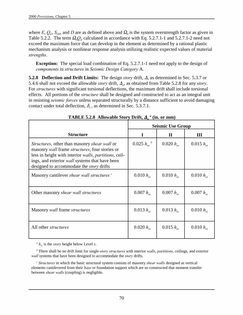
2000 Provisions, Chapter 5
70
where E, QE, SDS, and D are as defined above and S0 is the system overstrength factor as given inTable 5.2.2. The term S0QE calculated in accordance with Eq. 5.2.7.1-1 and 5.2.7.1-2 need notexceed the maximum force that can develop in the element as determined by a rational plasticmechanism analysis or nonlinear response analysis utilizing realistic expected values of materialstrengths.
Exception: The special load combination of Eq. 5.2.7.1-1 need not apply to the design ofcomponents in structures in Seismic Design Category A.
5.2.8 Deflection and Drift Limits: The design story drift, ), as determined in Sec. 5.3.7 or5.4.6 shall not exceed the allowable story drift, )a, as obtained from Table 5.2.8 for any story. For structures with significant torsional deflections, the maximum drift shall include torsionaleffects. All portions of the structure shall be designed and constructed to act as an integral unitin resisting seismic forces unless separated structurally by a distance sufficient to avoid damagingcontact under total deflection, *x , as determined in Sec. 5.3.7.1.
TABLE 5.2.8 Allowable Story Drift, ))))a a (in. or mm)
Structure
Seismic Use Group
I II III
Structures, other than masonry shear wall ormasonry wall frame structures, four stories orless in height with interior walls, partitions, ceil-ings, and exterior wall systems that have beendesigned to accommodate the story drifts
0.025 hsx b 0.020 hsx 0.015 hsx
Masonry cantilever shear wall structures c 0.010 hsx 0.010 hsx 0.010 hsx
Other masonry shear wall structures 0.007 hsx 0.007 hsx 0.007 hsx
Masonry wall frame structures 0.013 hsx 0.013 hsx 0.010 hsx
All other structures 0.020 hsx 0.015 hsx 0.010 hsx
a hsx is the story height below Level x.
b There shall be no drift limit for single-story structures with interior walls, partitions, ceilings, and exteriorwall systems that have been designed to accommodate the story drifts.
c Structures in which the basic structural system consists of masonry shear walls designed as verticalelements cantilevered from their base or foundation support which are so constructed that moment transferbetween shear walls (coupling) is negligible.
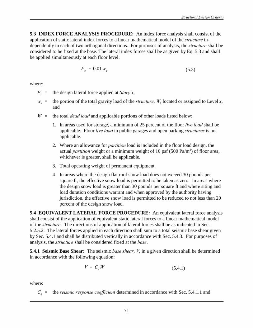
Structural Design Criteria
71
Fx ' 0.01wx (5.3)
V ' Cs W (5.4.1)
5.3 INDEX FORCE ANALYSIS PROCEDURE: An index force analysis shall consist of theapplication of static lateral index forces to a linear mathematical model of the structure in-dependently in each of two orthogonal directions. For purposes of analysis, the structure shall beconsidered to be fixed at the base. The lateral index forces shall be as given by Eq. 5.3 and shallbe applied simultaneously at each floor level:
where:
Fx = the design lateral force applied at Story x,
wx = the portion of the total gravity load of the structure, W, located or assigned to Level x,and
W = the total dead load and applicable portions of other loads listed below:
1. In areas used for storage, a minimum of 25 percent of the floor live load shall beapplicable. Floor live load in public garages and open parking structures is notapplicable.
2. Where an allowance for partition load is included in the floor load design, theactual partition weight or a minimum weight of 10 psf (500 Pa/m2) of floor area,whichever is greater, shall be applicable.
3. Total operating weight of permanent equipment.
4. In areas where the design flat roof snow load does not exceed 30 pounds persquare ft, the effective snow load is permitted to be taken as zero. In areas wherethe design snow load is greater than 30 pounds per square ft and where siting andload duration conditions warrant and when approved by the authority havingjurisdiction, the effective snow load is permitted to be reduced to not less than 20percent of the design snow load.
5.4 EQUIVALENT LATERAL FORCE PROCEDURE: An equivalent lateral force analysisshall consist of the application of equivalent static lateral forces to a linear mathematical modelof the structure. The directions of application of lateral forces shall be as indicated in Sec.5.2.5.2. The lateral forces applied in each direction shall sum to a total seismic base shear givenby Sec. 5.4.1 and shall be distributed vertically in accordance with Sec. 5.4.3. For purposes ofanalysis, the structure shall be considered fixed at the base.
5.4.1 Seismic Base Shear: The seismic base shear, V, in a given direction shall be determinedin accordance with the following equation:
where:
Cs = the seismic response coefficient determined in accordance with Sec. 5.4.1.1 and
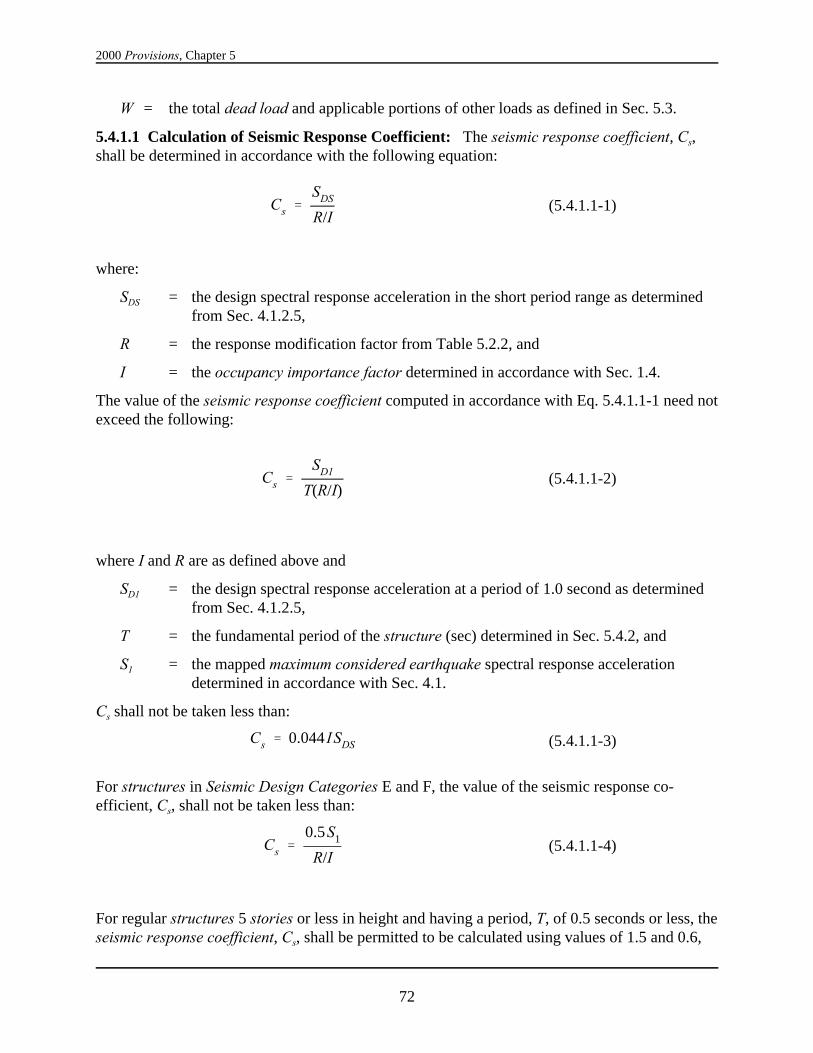
2000 Provisions, Chapter 5
72
Cs 'SDS
R/I(5.4.1.1-1)
Cs 'SD1
T(R/I)(5.4.1.1-2)
Cs ' 0.044 ISDS (5.4.1.1-3)
Cs '0.5S1
R/I(5.4.1.1-4)
W = the total dead load and applicable portions of other loads as defined in Sec. 5.3.
5.4.1.1 Calculation of Seismic Response Coefficient: The seismic response coefficient, Cs,shall be determined in accordance with the following equation:
where:
SDS = the design spectral response acceleration in the short period range as determinedfrom Sec. 4.1.2.5,
R = the response modification factor from Table 5.2.2, and
I = the occupancy importance factor determined in accordance with Sec. 1.4.
The value of the seismic response coefficient computed in accordance with Eq. 5.4.1.1-1 need notexceed the following:
where I and R are as defined above and
SD1 = the design spectral response acceleration at a period of 1.0 second as determinedfrom Sec. 4.1.2.5,
T = the fundamental period of the structure (sec) determined in Sec. 5.4.2, and
S1 = the mapped maximum considered earthquake spectral response accelerationdetermined in accordance with Sec. 4.1.
Cs shall not be taken less than:
For structures in Seismic Design Categories E and F, the value of the seismic response co-efficient, Cs, shall not be taken less than:
For regular structures 5 stories or less in height and having a period, T, of 0.5 seconds or less, theseismic response coefficient, Cs, shall be permitted to be calculated using values of 1.5 and 0.6,

Structural Design Criteria
73
Ta ' Cr h xn (5.4.2.1-1)
respectively, for the mapped maximum considered earthquake spectral response accelerations, SS
and S1.
A soil-structure interaction reduction is permitted when determined using Sec. 5.8 or othergenerally accepted procedures approved by the authority having jurisdiction.
5.4.2 Period Determination: The fundamental period of the building, T, in the direction underconsideration shall be established using the structural properties and deformational characteris-tics of the resisting elements in a properly substantiated analysis. The fundamental period, T, socalculated, shall not exceed the product of the coefficient for the upper limit on calculated period,Cu, from Table 5.4.2 and the approximate fundamental period, Ta, calculated in accordance withSec. 5.4.2.1. The approximate period formulae of Sec. 5.4.2.1 is permitted to be used directly asan alternative to performing an analysis to determine the fundamental period of the building, T.
TABLE 5.4.2 Coefficient for Upper Limit on Calculated Period
Design SpectralResponse Acceleration at 1 Second, SD1 Coefficient Cu
Greater than or equal to 0.4 1.4
0.3 1.4
0.2 1.5
0.15 1.6
0.1 1.7
Less than or equal to 0.05 1.7
5.4.2.1 Approximate Fundamental Period: The approximate fundamental period, Ta, inseconds, shall be determined from the following equation:
where hn is the height (ft or m) above the base to the highest level of the structure and the valuesof Cr and x shall be determined from Table 5.4.2.1.

2000 Provisions, Chapter 5
74
Ta ' 0.1N (5.4.2.1-2)
Ta '0.0019
Cw
hn Ta '0.0062
CW
hn (5.4.2.1-3)
Cw '100AB
jn
i ' 1
hn
hi
Ai
1 % 0.83hn
D
2 (5.4.2.1-4)
TABLE 5.4.2.1 Values of Approximate Period Parameters Cr and x
Structure Type COT x
Moment resisting frame systems of steel in which theframes resist 100 percent of the required seismic forceand are not enclosed or adjoined by more rigid com-ponents that will prevent the frames from deflecting whensubjected to seismic forces.
0.028(metric 0.0724)
0.8
Moment resisting frame systems of reinforced concrete inwhich the frames resist 100 percent of the required seis-mic force and are not enclosed or adjoined by more rigidcomponents that will prevent the frames from deflectingwhen subjected to seismic forces.
0.016(metric 0.0466)
0.9
Eccentrically braced steel frames 0.03(metric 0.0731)
0.75
All other structural systems 0.02(metric 0.0488)
0.75
Alternatively, the approximate fundamental period, Ta, in seconds, is permitted to be determinedfrom the following equation for concrete and steel moment resisting frame structures notexceeding 12 stories in height and having a minimum story height of 10 ft (3 m):
where N = number of stories.
The approximate fundamental period, Ta, in seconds, for masonry or concrete shear wallstructures is permitted to be determined from the following equation:
where Cw is a coefficient related to the effective shear wall area and hn is as defined above. The coefficient Cw shall be calculated from the following equation:

Structural Design Criteria
75
Fx ' Cvx V (5.4.3-1)
Cvx 'wx h k
x
3n
i'1wi h
ki
(5.4.3-2)
Vx ' 3n
i'xFi (5.4.4)
where:
AB = the base area of the structure (ft2. or m2),
Ai = the area of shear wall i (ft2. or m2),
Di = the length of shear wall i (ft or m),
hi = the height of shear wall i (ft or m), and
n = the number of shear walls in the building effective in resisting lateral forces in thedirection under consideration.
5.4.3 Vertical Distribution of Seismic Forces: The lateral force, Fx (kip or kN), induced at anylevel shall be determined from the following equations:
and
where:
Cvx = vertical distribution factor,
V = total design lateral force or shear at the base of the structure (kip or kN),
wi and wx = the portion of the total gravity load of the structure, W, located or assigned toLevel i or x,
hi and hx = the height (ft or m) from the base to Level i or x, and
k = an exponent related to the structure period as follows:
For structures having a period of 0.5 seconds or less, k = 1
For structures having a period of 2.5 seconds or more, k = 2
For structures having a period between 0.5 and 2.5 seconds, k shall be 2 orshall be determined by linear interpolation between 1 and 2
5.4.4 Horizontal Shear Distribution: The seismic design story shear in any story, Vx (kip orkN), shall be determined from the following equation:

2000 Provisions, Chapter 5
76
Ax '*max
1.2*avg
2
(5.4.4.3-1)
Mx ' 3n
i & xFi (hi & hx ) (5.4.5)
where Fi = the portion of the seismic base shear, V (kip or kN), induced at Level i.
The seismic design story shear, Vx (kip or kN), shall be distributed to the various verticalelements of the seismic-force-resisting system in the story under consideration based on therelative lateral stiffnesses of the vertical-resisting elements and the diaphragm.
5.4.4.1 Inherent Torsion: The distribution of lateral forces at each level shall consider theeffect of the inherent torsional moment, Mt (kip"ft or kN"m), resulting from eccentric location ofthe masses.
5.4.4.2. Accidental Torsion: In addition to the inherent torsional moment, the distribution oflateral forces also shall include accidental torsional moments, Mta (kip"ft or kN"m), caused by anassumed displacement of the mass each way from its actual location by a distance equal to 5percent of the dimension of the structure perpendicular to the direction of the applied forces.
5.4.4.3 Dynamic Amplification of Torsion: For structures of Seismic Design Categories C, D,E and F where Type 1a or 1b torsional irregularity exists as defined in Table 5.2.3.1, the effectsof torsional irregularity shall be accounted for by multiplying the sum of Mt plus Mta at each levelby a torsional amplification factor, Ax, determined from the following equation:
where:
*max = the maximum displacement at Level x (in. or mm) and
*avg = the average of the displacements at the extreme points of the structure at Level x(in. or mm).
The torsional amplification factor, Ax, is not required to exceed 3.0. The more severe loading foreach element shall be considered for design.
5.4.5 Overturning: The structure shall be designed to resist overturning effects caused by theseismic forces determined in Sec. 5.3.4. At any story, the increment of overturning moment inthe story under consideration shall be distributed to the various vertica- force-resisting elementsin the same proportion as the distribution of the horizontal shears to those elements.
The overturning moments at Level x, Mx (kip"ft or kN"m), shall be determined from the followingequation:
where:
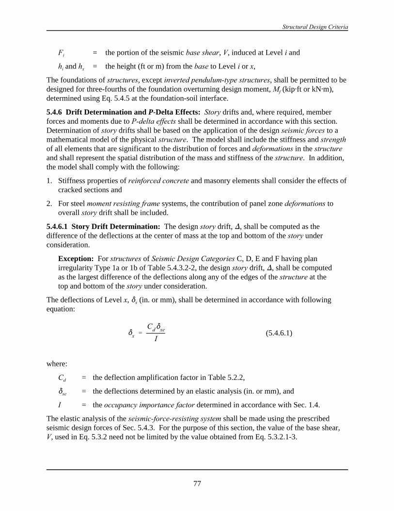
Structural Design Criteria
77
*x 'Cd*xe
I(5.4.6.1)
Fi = the portion of the seismic base shear, V, induced at Level i and
hi and hx = the height (ft or m) from the base to Level i or x,
The foundations of structures, except inverted pendulum-type structures, shall be permitted to bedesigned for three-fourths of the foundation overturning design moment, Mf (kip"ft or kN"m),determined using Eq. 5.4.5 at the foundation-soil interface.
5.4.6 Drift Determination and P-Delta Effects: Story drifts and, where required, memberforces and moments due to P-delta effects shall be determined in accordance with this section. Determination of story drifts shall be based on the application of the design seismic forces to amathematical model of the physical structure. The model shall include the stiffness and strengthof all elements that are significant to the distribution of forces and deformations in the structureand shall represent the spatial distribution of the mass and stiffness of the structure. In addition,the model shall comply with the following:
1. Stiffness properties of reinforced concrete and masonry elements shall consider the effects ofcracked sections and
2. For steel moment resisting frame systems, the contribution of panel zone deformations tooverall story drift shall be included.
5.4.6.1 Story Drift Determination: The design story drift, ), shall be computed as thedifference of the deflections at the center of mass at the top and bottom of the story underconsideration.
Exception: For structures of Seismic Design Categories C, D, E and F having planirregularity Type 1a or 1b of Table 5.4.3.2-2, the design story drift, ), shall be computedas the largest difference of the deflections along any of the edges of the structure at thetop and bottom of the story under consideration.
The deflections of Level x, *x (in. or mm), shall be determined in accordance with followingequation:
where:
Cd = the deflection amplification factor in Table 5.2.2,
*xe = the deflections determined by an elastic analysis (in. or mm), and
I = the occupancy importance factor determined in accordance with Sec. 1.4.
The elastic analysis of the seismic-force-resisting system shall be made using the prescribedseismic design forces of Sec. 5.4.3. For the purpose of this section, the value of the base shear,V, used in Eq. 5.3.2 need not be limited by the value obtained from Eq. 5.3.2.1-3.

2000 Provisions, Chapter 5
78
2 'Px)
Vx hsx Cd
(5.4.6.2-1)
2max '0.5$Cd
# 0.25 (5.4.6.2-2)
For determining compliance with the story drift limitation of Sec. 5.2.8, the deflections of Levelx, *x (in. or mm), shall be calculated as required in this section. For purposes of this driftanalysis only, it is permissible to use the computed fundamental period, T (secs), of the structurewithout the upper bound limitation specified in Sec. 5.4.2 when determining drift level seismicdesign forces.
Where applicable, the design story drift, ) (in. or mm), shall be increased by the incrementalfactor relating to the P-delta effects as determined in Sec. 5.4.6.2.
5.4.6.2 P-Delta Effects: P-delta effects on story shears and moments, the resulting memberforces and moments, and the story drifts induced by these effects are not required to be con-sidered when the stability coefficient, 2, as determined by the following equation is equal to orless than 0.10:
where:
Px = the total vertical design load at and above Level x (kip or kN). When calculatingthe vertical design load for purposes of determining P-delta, the individual loadfactors need not exceed 1.0.
) = the design story drift occurring simultaneously with Vx (in. or mm).
Vx = the seismic shear force acting between Level x and x - 1 (kip or kN).
hsx = the story height below Level x (in. or mm).
Cd = the deflection amplification factor in Table 5.2.2.
The stability coefficient, 2, shall not exceed 2max determined as follows:
where $ is the ratio of shear demand to shear capacity for the story between Levels x and x - 1. This ratio is permitted to be conservatively taken as 1.0.
When the stability coefficient, 2, is greater than 0.10 but less than or equal to 2max, the in-cremental factor related to P-delta effects, ad, shall be determined by rational analysis (see Part 2,Commentary). To obtain the story drift for including the P-delta effects, the design story driftdetermined in Sec. 5.4.6.1 shall be permitted to be multiplied by 1.0/(1 - 2).
When 2 is greater than 2max, the structure is potentially unstable and shall be redesigned.
5.5 MODAL RESPONSE SPECTRUM ANALYSIS PROCEDURE: A modal responsespectrum analysis shall consist of the analysis of a linear mathematical model of the structure to
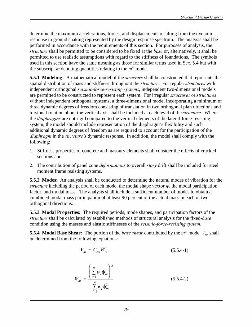
Structural Design Criteria
79
Vm ' Csm Wm (5.5.4-1)
Wm '
3n
i'1wiNim
2
3n
i'1wiN
2im
(5.5.4-2)
determine the maximum accelerations, forces, and displacements resulting from the dynamicresponse to ground shaking represented by the design response spectrum. The analysis shall beperformed in accordance with the requirements of this section. For purposes of analysis, thestructure shall be permitted to be considered to be fixed at the base or, alternatively, it shall bepermitted to use realistic assumptions with regard to the stiffness of foundations. The symbolsused in this section have the same meaning as those for similar terms used in Sec. 5.4 but withthe subscript m denoting quantities relating to the mth mode.
5.5.1 Modeling: A mathematical model of the structure shall be constructed that represents thespatial distribution of mass and stiffness throughout the structure. For regular structures withindependent orthogonal seismic-force-resisting systems, independent two-dimensional modelsare permitted to be constructed to represent each system. For irregular structures or structureswithout independent orthogonal systems, a three-dimensional model incorporating a minimum ofthree dynamic degrees of freedom consisting of translation in two orthogonal plan directions andtorsional rotation about the vertical axis shall be included at each level of the structure. Wherethe diaphragms are not rigid compared to the vertical elements of the lateral-force-resistingsystem, the model should include representation of the diaphragm’s flexibility and suchadditional dynamic degrees of freedom as are required to account for the participation of thediaphragm in the structure’s dynamic response. In addition, the model shall comply with thefollowing:
1. Stiffness properties of concrete and masonry elements shall consider the effects of crackedsections and
2. The contribution of panel zone deformations to overall story drift shall be included for steelmoment frame resisting systems.
5.5.2 Modes: An analysis shall be conducted to determine the natural modes of vibration for thestructure including the period of each mode, the modal shape vector N, the modal participationfactor, and modal mass. The analysis shall include a sufficient number of modes to obtain acombined modal mass participation of at least 90 percent of the actual mass in each of twoorthogonal directions.
5.5.3 Modal Properties: The required periods, mode shapes, and participation factors of thestructure shall be calculated by established methods of structural analysis for the fixed-basecondition using the masses and elastic stiffnesses of the seismic-force-resisting system.
5.5.4 Modal Base Shear: The portion of the base shear contributed by the mth mode, Vm, shallbe determined from the following equations:
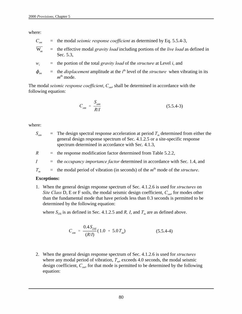
2000 Provisions, Chapter 5
80
Csm 'Sam
R/I(5.5.4-3)
Csm '0.4SDS
(R/I)(1.0 % 5.0Tm) (5.5.4-4)
where:
Csm = the modal seismic response coefficient as determined by Eq. 5.5.4-3,
= the effective modal gravity load including portions of the live load as defined inWmSec. 5.3,
wi = the portion of the total gravity load of the structure at Level i, and
Nim = the displacement amplitude at the ith level of the structure when vibrating in itsmth mode.
The modal seismic response coefficient, Csm, shall be determined in accordance with thefollowing equation:
where:
Sam = The design spectral response acceleration at period Tm determined from either thegeneral design response spectrum of Sec. 4.1.2.5 or a site-specific responsespectrum determined in accordance with Sec. 4.1.3,
R = the response modification factor determined from Table 5.2.2,
I = the occupancy importance factor determined in accordance with Sec. 1.4, and
Tm = the modal period of vibration (in seconds) of the mth mode of the structure.
Exceptions:
1. When the general design response spectrum of Sec. 4.1.2.6 is used for structures onSite Class D, E or F soils, the modal seismic design coefficient, Csm, for modes otherthan the fundamental mode that have periods less than 0.3 seconds is permitted to bedetermined by the following equation:
where SDS is as defined in Sec. 4.1.2.5 and R, I, and Tm are as defined above.
2. When the general design response spectrum of Sec. 4.1.2.6 is used for structureswhere any modal period of vibration, Tm, exceeds 4.0 seconds, the modal seismicdesign coefficient, Csm, for that mode is permitted to be determined by the followingequation:
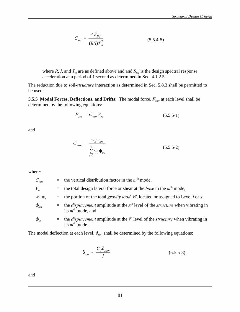
Structural Design Criteria
81
Csm '4SD1
(R/I)T 2m
(5.5.4-5)
Fxm ' Cvxm Vm (5.5.5-1)
Cvxm 'wxNxm
3n
i'1wiNim
(5.5.5-2)
*xm 'Cd*xem
I(5.5.5-3)
where R, I, and Tm are as defined above and and SD1 is the design spectral responseacceleration at a period of 1 second as determined in Sec. 4.1.2.5.
The reduction due to soil-structure interaction as determined in Sec. 5.8.3 shall be permitted tobe used.
5.5.5 Modal Forces, Deflections, and Drifts: The modal force, Fxm, at each level shall bedetermined by the following equations:
and
where:
Cvxm = the vertical distribution factor in the mth mode,
Vm = the total design lateral force or shear at the base in the mth mode,
wi, wx = the portion of the total gravity load, W, located or assigned to Level i or x,
Nxm = the displacement amplitude at the xth level of the structure when vibrating inits mth mode, and
Nim = the displacement amplitude at the ith level of the structure when vibrating inits mth mode.
The modal deflection at each level, *xm, shall be determined by the following equations:
and

2000 Provisions, Chapter 5
82
*xem 'g
4B2
T 2m Fxm
wx
(5.5.5-4)
0.85VVt
(5.5.7.1)
where:
Cd = the deflection amplification factor determined from Table 5.2.2,
*xem = the deflection of Level x in the mth mode at the center of the mass at Level xdetermined by an elastic analysis,
g = the acceleration due to gravity (ft/s2 or m/s2),
I = the occupancy importance factor determined in accordance with Sec. 1.4,
Tm = the modal period of vibration, in seconds, of the mth mode of the structure,
Fxm = the portion of the seismic base shear in the mth mode, induced at Level x, and
wx = the portion of the total gravity load of the structure, W, located or assigned toLevel x.
The modal drift in a story, )m, shall be computed as the difference of the deflections, *xm, at thetop and bottom of the story under consideration.
5.5.6 Modal Story Shears and Moments: The story shears, story overturning moments, andthe shear forces and overturning moments in vertical elements of the structural system at eachlevel due to the seismic forces determined from the appropriate equation in Sec. 5.5.5 shall becomputed for each mode by linear static methods.
5.5.7 Design Values: The design value for the modal base shear, Vt; each of the story shear,moment, and drift quantities; and the deflection at each level shall be determined by combiningtheir modal values as obtained from Sec. 5.5.5 and 5.5.6. The combination shall be carried outby taking the square root of the sum of the squares of each of the modal values or by thecomplete quadratic combination technique. The complete quadratic combination shall be usedwhere closely spaced periods in the translational and torsional modes will result in cross-correlation of the modes.
A base shear, V, shall be calculated using the equivalent lateral force procedure in Sec. 5.4. Forthe purpose of this calculation, the fundamental period of the structure, T (sec), shall not exceedthe coefficient for upper limit on the calculated period, Cu, times the approximate fundamentalperiod of the structure, Ta. Where the design value for the modal base shear, Vt, is less than 85percent of the calculated base shear, V, using the equivalent lateral force procedure, the designstory shears, moments, drifts, and floor deflections shall be multiplied by the followingmodification factor:

Structural Design Criteria
83
where:
V = the equivalent lateral force procedure base shear calculated in accordance with Sec.5.4 and
Vt = the modal base shear calculated in accordance with this section.
Where soil-structure interaction in accordance with Sec. 5.8 is considered, the reduced value of Vcalculated in accordance with that section may be used for V in Eq. 5.5.7.1.
5.5.8 Horizontal Shear Distribution: The horizontal distribution of shear shall be in ac-cordance with the requirements of Sec. 5.4.4 except that amplification of torsion per Sec.5.4.4.1.3 is not required for that portion of the torsion included in the dynamic analysis model.
5.5.9 Foundation Overturning: The foundation overturning moment at the foundation-soilinterface shall be permitted to be reduced by 10 percent.
5.5.10 P-Delta Effects: The P-delta effects shall be determined in accordance with Sec. 5.4.6. The story drifts and story shears shall be determined in accordance with Sec. 5.4.6.1.
5.6 LINEAR RESPONSE HISTORY ANALYSIS PROCEDURE: A linear response historyanalysis shall consist of an analysis of a linear mathematical model of the structure to determineits response, through methods of numerical integration, to suites of ground motion accelerationhistories compatible with the design response spectrum for the site. The analysis shall beperformed in accordance with the provisions of this section. For the purposes of analysis, thestructure shall be permitted to be considered to be fixed at the base or, alternatively, it shall bepermitted to use realistic assumptions with regard to the stiffness of foundations.
5.6.1 Modeling: Mathematical models shall conform to the requirements of Sec. 5.5.1.
5.6.2 Ground Motion: A suite of not less than three appropriate ground motions shall be usedin the analysis. Ground motion shall conform to the requirements of this section.
5.6.2.1 Two-Dimensional Analysis: When two-dimensional analyses are performed, eachground motion shall consist of a horizontal acceleration history selected from an actual recordedevent. Appropriate acceleration histories shall be obtained from records of events havingmagnitudes, fault distances, and source mechanisms that are consistent with those that control themaximum considered earthquake. Where the required number of appropriate recorded groundmotion records are not available, appropriate simulated ground motion records shall be used tomake up the total number required. The ground motions shall be scaled such that the averagevalue of the 5 percent damped response spectra for the suite of motions is not less than the designresponse spectrum for the site determined in accordance with Sec. 4.1.3 for periods ranging from0.2T to 1.5T seconds where T is the natural period of the structure in the fundamental mode forthe direction of response being analyzed.
5.6.2.2 Three-Dimensional Analysis: When three-dimensional analysis is performed, groundmotions shall consist of pairs of appropriate horizontal ground motion acceleration componentsthat shall be selected and scaled from individual recorded events. Appropriate ground motionsshall be selected from events having magnitudes, fault distances, and source mechanisms that areconsistent with those that control the maximum considered earthquake. Where the required

2000 Provisions, Chapter 5
84
number of recorded ground motion pairs are not available, appropriate simulated ground motionpairs shall be used to make up the total number required. For each pair of horizontal groundmotion components, the square root of the sum of the squares (SRSS) of the 5 percent dampedresponse spectrum of the scaled horizontal components shall be constructed. Each pair ofmotions shall be scaled such that the average value of the SRSS spectra from all horizontalcomponent pairs is not less than 1.3 times the 5 percent damped design response spectrumdetermined in accordance with Sec. 4.1.3 for periods ranging from 0.2T to 1.5T seconds where Tis the natural period of the fundamental mode of the structure.
5.6.3 Response Parameters: For each ground motion analyzed, the individual responseparameters shall be scaled by the quantity I/R where I is the occupancy importance factordetermined in accordance with Sec. 1.4 and R is the response modification coefficient selected inaccordance with Sec. 5.2.2. The maximum value of the base shear, Vj, member forces, QEj, andthe interstory drifts, *ij, at each story scaled as indicated above shall be determined. When themaximum scaled base shear predicted by the analysis, Vj, is less than given by Eq. 5.4.1.1-3 or, inSeismic Design Categories E and F, Eq. 5.4.1.1-4, the scaled member forces, QEj, shall beadditionally scaled by the factor V/Vj where V is the minimum base shear determined in accor-dance with Eq. 5.4.1.1-3 or, for structures in Seismic Design Category E or F, Eq. 5.4.1.1-4.
If at least seven ground motions are analyzed, the design member forces, QE, used in the loadcombinations of Sec. 5.2.7 and the design interstory drift, ), used in the evaluation of drift inaccordance with Sec. 5.2.8 shall be permitted to be taken, respectively, as the average of thescaled QEj and *ij values determined from the analyses and scaled as indicated above. If less thanseven ground motions are analyzed, the design member forces, QE, and the design interstory drift,), shall be taken as the maximum value of the scaled QEj and *ij values determined from theanalyses.
Where the Provisions require the consideration of the special load combinations of Sec. 5.2.7.1,the value of S0QE need not be taken larger than the maximum of the unscaled value, QEj,obtained from the suite of analyses.
5.7 NONLINEAR RESPONSE HISTORY ANALYSIS PROCEDURE : A nonlinearresponse history analysis shall consist of an analysis of a mathematical model of the structurethat directly accounts for the nonlinear hysteretic behavior of the structure's components todetermine its response, through methods of numerical integration, to suites of ground motionacceleration histories compatible with the design response spectrum for the site. The analysisshall be performed in accordance with the requirements of this section.
5.7.1 Modeling: A mathematical model of the structure shall be constructed that represents thespatial distribution of mass throughout the structure. The hysteretic behavior of elements shallbe modeled consistent with suitable laboratory test data and shall account for all significantyielding, strength degradation, stiffness degradation, and hysteretic pinching indicated by suchtest data. Strength of elements shall be based on expected values considering material over-strength, strain hardening, and hysteretic strength degradation. Linear properties consistent withthe provisions of Sec. 5.5.1 shall be permitted to be used for those elements demonstrated by theanalysis to remain within their linear range of response. The structure shall be assumed to have afixed base or, alternatively, it shall be permitted to use realistic assumptions with regard to the

Structural Design Criteria
85
stiffness and load carrying characteristics of the foundations consistent with site-specific soilsdata and rational principles of engineering mechanics.
For regular structures with independent orthogonal seismic-force-resisting systems, independenttwo-dimensional models shall be permitted to be constructed to represent each system. Forstructures having plan irregularity Type 1a, 1b, 4, or 5 of Table 5.2.3.2 or structures withoutindependent orthogonal systems, a three-dimensional model incorporating a minimum of threedynamic degrees of freedom consisting of translation in two orthogonal plan directions andtorsional rotation about the vertical axis at each level of the structure shall be used. Where thediaphragms are not rigid compared to the vertical elements of the lateral-force-resisting system,the model shall include representation of the diaphragm's flexibility and such additional dynamicdegrees of freedom as are required to account for the participation of the diaphragm in thestructure's dynamic response.
5.7.2 Ground Motion and Other Loading: Ground motion shall conform to the requirementsof Sec. 5.6.2. The structure shall be analyzed for the effects of these ground motions simul-taneously with the effects of dead load in combination with not less than 25 percent of therequired live loads.
5.7.3 Response Parameters: For each ground motion analyzed, individual response parametersconsisting of the maximum value of the individual member forces, QEj, member inelasticdeformations, (j, and interstory drifts, *ij, at each story shall be determined.
If at least seven ground motions are analyzed, the design values of member forces, QE, memberinelastic deformations, (i, and interstory drift, ) , shall be taken, respectively, as the average ofthe scaled QEj, (i, and *i values determined from the analyses. If less than seven ground motionsare analyzed, the design member forces, QE, design member inelastic deformations, (i and thedesign interstory drift, ), shall be taken as the maximum value of the scaled QEj, (j, and *ij valuesdetermined from the analyses.
5.7.3.1 Member Strength: The adequacy of members to resist the load combinations of Sec5.2.7 need not be evaluated.
Exception: Where the Provisions requires the consideration of the special load com-binations of Sec. 5.2.7.1, the maximum value of QEj obtained from the suite of analysesshall be taken in place of the quantity S0QE.
5.7.3.2 Member Deformation:. The adequacy of individual members and their connections towithstand the design deformation values, (i, predicted by the analyses shall be evaluated basedon laboratory test data for similar components. The effects of gravity and other loads on memberdeformation capacity shall be considered in these evaluations. Member deformation shall notexceed two thirds of the value that results in loss of ability to carry gravity loads or that results indeterioration of member strength to less than the 67 percent of the peak value.
5.7.3.3 Interstory Drift: The design interstory drift obtained from the analyses shall not exceed125 percent of the drift limit specified in Sec. 5.2.8.
5.7.4 Design Review: A design review of the seismic-force-resisting system and the structuralanalysis shall be performed by an independent team of registered design professionals in the
2000 Provisions, Chapter 5
86
V ' V & )V (5.8.2.1-1)
)V ' Cs & Cs0.05
$
0.4
W (5.8.2.1-2)
appropriate disciplines and others experienced in seismic analysis methods and the theory andapplication of nonlinear seismic analysis and structural behavior under extreme cyclic loads. Thedesign review shall include, but not be limited to, the following:
1. Review of any site-specific seismic criteria employed in the analysis including the develop-ment of site-specific spectra and ground motion time histories,
2. Review of acceptance criteria used to demonstrate the adequacy of structural elements andsystems to withstand the calculated force and deformation demands, together with thatlaboratory and other data used to substantiate these criteria,
3. Review of the preliminary design including the determination of the target displacement ofthe structure and the margins remaining beyond these displacements, and
4. Review of the final design of the entire structural system and all supporting analyses.
5.8 SOIL-STRUCTURE INTERACTION EFFECTS:
5.8.1 General: The requirements set forth in this section are permitted to be used to incorporatethe effects of soil-structure interaction in the determination of the design earthquake forces andthe corresponding displacements of the structure. The use of these requirements will decreasethe design values of the base shear, lateral forces, and overturning moments but may increase thecomputed values of the lateral displacements and the secondary forces associated with theP-delta effects.
The requirements for use with the equivalent lateral force procedure are given in Sec. 5.8.2 andthose for use with the modal analysis procedure are given in Sec. 5.8.3.
5.8.2 Equivalent Lateral Force Procedure: The following requirements are supplementary tothose presented in Sec. 5.4.
5.8.2.1 Base Shear: To account for the effects of soil-structure interaction, the base shear, V,determined from Eq. 5.4.1-1 may be reduced to:
The reduction, )V, shall be computed as follows:
where:
Cs = the seismic response coefficient computed from Eq. 5.4.1.1-1 using the fundamentalnatural period of the fixed-base structure (T or Ta) as specified in Sec.5.4.2,
= the seismic response coefficient computed from Eq. 5.4.1.1-1 using the fundamentalCsnatural period of the flexibly supported structure ( ) defined in Sec. 5.8.2.1.1,T
Structural Design Criteria
87
T'T 1 %k
Ky
1 %Ky h 2
K2
(5.8.2.1.1-1)
k ' 4B2 W
gT 2(5.8.2.1.1-2)
= the fraction of critical damping for the structure-foundation system determined inBSec. 5.8.2.1.2, and
= the effective gravity load of the structure, which shall be taken as 0.7W, except thatWfor structures where the gravity load is concentrated at a single level, it shall be takenequal to W.
The reduced base shear, , shall in no case be taken less than 0.7V.V
5.8.2.1.1 Effective Building Period: The effective period, , shall be determined as follows:T
where:
T = the fundamental period of the structure as determined in Sec. 5.4.2;
= the stiffness of the structure when fixed at the base, defined by the following:k
= the effective height of the structure, which shall be taken as 0.7 times the totalhheight, hn, except that for structures where the gravity load is effectively concen-trated at a single level, it shall be taken as the height to that level;
Ky = the lateral stiffness of the foundation defined as the horizontal force at the level ofthe foundation necessary to produce a unit deflection at that level, the force andthe deflection being measured in the direction in which the structure is analyzed;
K2 = the rocking stiffness of the foundation defined as the moment necessary toproduce a unit average rotation of the foundation, the moment and rotation beingmeasured in the direction in which the structure is analyzed; and
g = the acceleration of gravity.
The foundation stiffnesses, Ky and K2, shall be computed by established principles of foundationmechanics (see the Commentary) using soil properties that are compatible with the soil strainlevels associated with the design earthquake motion. The average shear modulus, G, for the soilsbeneath the foundation at large strain levels and the associated shear wave velocity, vs, needed inthese computations shall be determined from Table 5.8.2.1.1 where:
vso = the average shear wave velocity for the soils beneath the foundation at small strainlevels (10-3 percent or less),
Go = (v2so/g = the average shear modulus for the soils beneath the foundation at small
strain levels, and
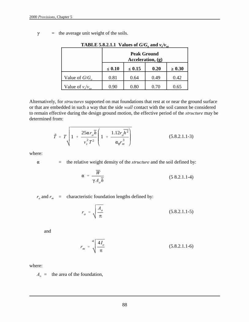
2000 Provisions, Chapter 5
88
T ' T 1 %25"ra h
v 2s T 2
1 %1.12rah
2
"2r3m
(5.8.2.1.1-3)
" 'W
(Ao h(5 8.2.1.1-4)
ra 'Ao
B(5.8.2.1.1-5)
rm '
4 4 Io
B(5.8.2.1.1-6)
( = the average unit weight of the soils.
TABLE 5.8.2.1.1 Values of G/Go and vs/vso
Peak Ground Acceleration, (g)
#### 0.10 #### 0.15 0.20 $$$$ 0.30
Value of G/Go 0.81 0.64 0.49 0.42
Value of vs/vso 0.90 0.80 0.70 0.65
Alternatively, for structures supported on mat foundations that rest at or near the ground surfaceor that are embedded in such a way that the side wall contact with the soil cannot be consideredto remain effective during the design ground motion, the effective period of the structure may bedetermined from:
where:
" = the relative weight density of the structure and the soil defined by:
ra and rm = characteristic foundation lengths defined by:
and
where:
Ao = the area of the foundation,

Structural Design Criteria
89
$ ' $o %0.05
TT
3(5.8.2.1.2-1)
r ' ra 'Ao
B(5.8.2.1.2-2)
r ' rm '
4 4 Io
B(5.8.2.1.2-3)
Io = the static moment of the foundation about a horizontal centroidal axis normal to thedirection in which the structure is analyzed, and
5.8.2.1.2 Effective Damping: The effective damping factor for the structure-foundation system,, shall be computed as follows:$
where $o = the foundation damping factor as specified in Figure 5.8.2.1.2.
The values of $o corresponding to SDS = 0.375 in Figure 5.8.2.1.2 shall be determined byaveraging the results obtained from the solid lines and the dashed lines.
The quantity r in Figure 5.8.2.1.2 is a characteristic foundation length that shall be determined asfollows:
For /Lo # 0.5,h
For /Lo $ 1,h
where:
Lo = the overall length of the side of the foundation in the direction being analyzed,
Ao = the area of the load-carrying foundation, and
Io = the static moment of inertia of the load-carrying foundation.
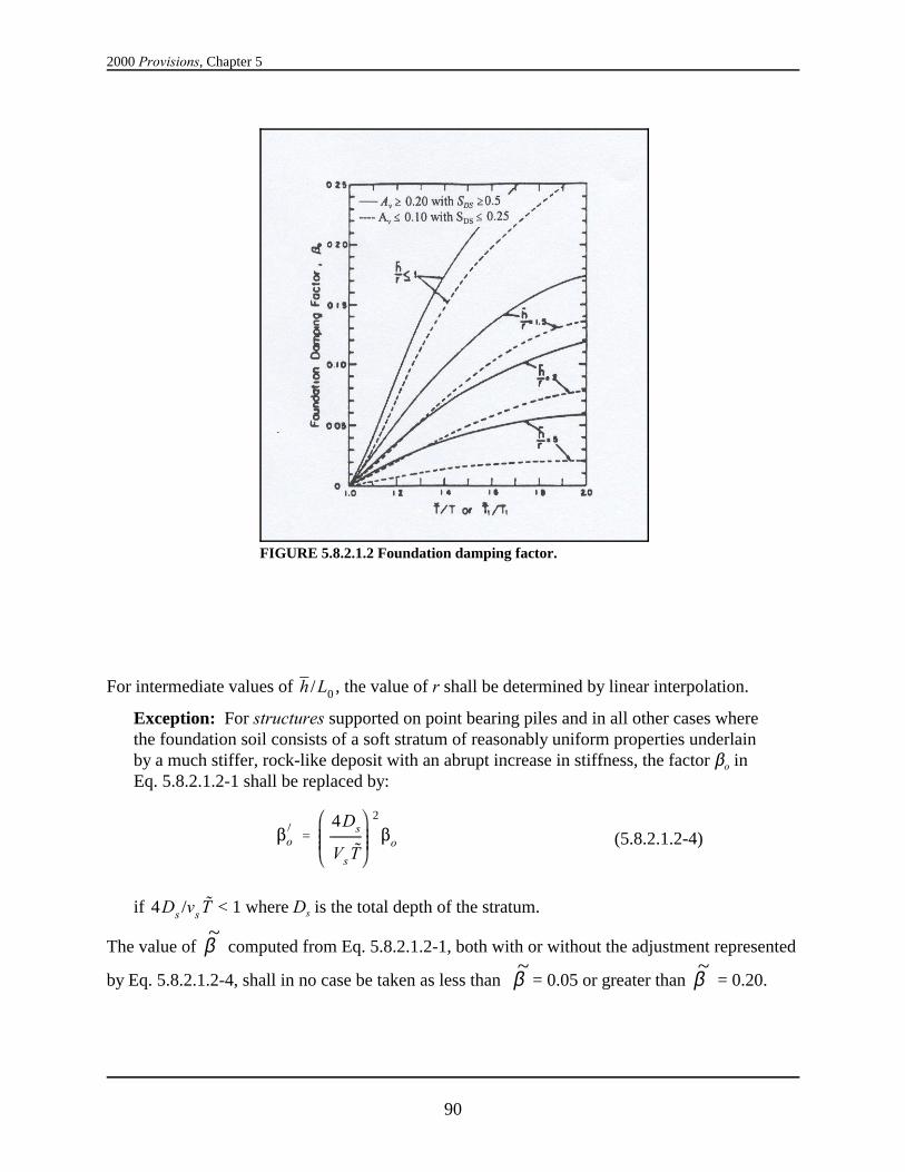
2000 Provisions, Chapter 5
90
FIGURE 5.8.2.1.2 Foundation damping factor.
$)
o '4Ds
Vs T
2
$o (5.8.2.1.2-4)
For intermediate values of , the value of r shall be determined by linear interpolation.h /L0
Exception: For structures supported on point bearing piles and in all other cases wherethe foundation soil consists of a soft stratum of reasonably uniform properties underlainby a much stiffer, rock-like deposit with an abrupt increase in stiffness, the factor $o inEq. 5.8.2.1.2-1 shall be replaced by:
if < 1 where Ds is the total depth of the stratum.4Ds /vs T
The value of computed from Eq. 5.8.2.1.2-1, both with or without the adjustment represented~β
by Eq. 5.8.2.1.2-4, shall in no case be taken as less than = 0.05 or greater than = 0.20.~β ~β
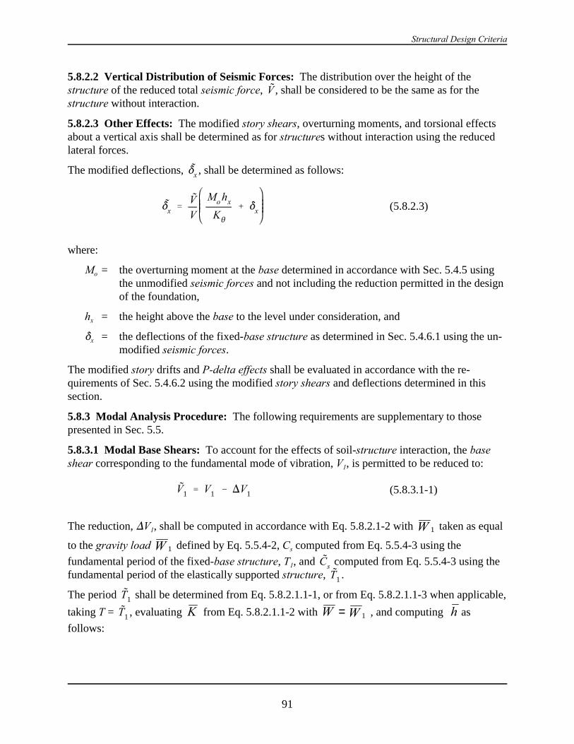
Structural Design Criteria
91
*x 'VV
Mo hx
K2
% *x (5.8.2.3)
V1 ' V1 & )V1 (5.8.3.1-1)
5.8.2.2 Vertical Distribution of Seismic Forces: The distribution over the height of thestructure of the reduced total seismic force, , shall be considered to be the same as for theVstructure without interaction.
5.8.2.3 Other Effects: The modified story shears, overturning moments, and torsional effectsabout a vertical axis shall be determined as for structures without interaction using the reducedlateral forces.
The modified deflections, , shall be determined as follows:*x
where:
Mo = the overturning moment at the base determined in accordance with Sec. 5.4.5 usingthe unmodified seismic forces and not including the reduction permitted in the designof the foundation,
hx = the height above the base to the level under consideration, and
*x = the deflections of the fixed-base structure as determined in Sec. 5.4.6.1 using the un-modified seismic forces.
The modified story drifts and P-delta effects shall be evaluated in accordance with the re-quirements of Sec. 5.4.6.2 using the modified story shears and deflections determined in thissection.
5.8.3 Modal Analysis Procedure: The following requirements are supplementary to thosepresented in Sec. 5.5.
5.8.3.1 Modal Base Shears: To account for the effects of soil-structure interaction, the baseshear corresponding to the fundamental mode of vibration, V1, is permitted to be reduced to:
The reduction, )V1, shall be computed in accordance with Eq. 5.8.2.1-2 with taken as equal1W
to the gravity load defined by Eq. 5.5.4-2, Cs computed from Eq. 5.5.4-3 using the1Wfundamental period of the fixed-base structure, T1, and computed from Eq. 5.5.4-3 using theCsfundamental period of the elastically supported structure, .T1
The period shall be determined from Eq. 5.8.2.1.1-1, or from Eq. 5.8.2.1.1-3 when applicable,T1
taking T = , evaluating from Eq. 5.8.2.1.1-2 with , and computing asT1 K W W= 1 hfollows:

2000 Provisions, Chapter 5
92
h '
3n
i'1wiNi1 hi
3n
i'1wiNi1
(5.8.3.1-2)
The above designated values of , T, and also shall be used to evaluate the factor " fromW h, TEq. 5.8.2.1.1-4 and the factor $o from Figure 5.8.2.1.2. No reduction shall be made in the shear
components contributed by the higher modes of vibration. The reduced base shear, , shall in1~
Vno case be taken less than 0.7V1.
5.8.3.2 Other Modal Effects: The modified modal seismic forces, story shears, and over-turning moments shall be determined as for structures without interaction using the modified
base shear, , instead of V1. The modified modal deflections, , shall be determined as1~
V *xm
follows:
xm
o xxl
VV
M h
K~
~δ δ
θ= +
1
1
1(5.8.3.2-1)
and
for m = 2, 3, ...... (5.8.3.2-2)xm x~δ δ=
where:
Mo1 = the overturning base moment for the fundamental mode of the fixed-base struc-ture, as determined in Sec. 5.5.6 using the unmodified modal base shear V1, and
*xm = the modal deflections at Level x of the fixed-base structure as determined inSec. 5.5.5 using the unmodified modal shears, Vm.
The modified modal drift in a story, , shall be computed as the difference of the deflections,)m, at the top and bottom of the story under consideration.*xm
5.8.3.3 Design Values: The design values of the modified shears, moments, deflections, andstory drifts shall be determined as for structures without interaction by taking the square root ofthe sum of the squares of the respective modal contributions. In the design of the foundation, theoverturning moment at the foundation-soil interface determined in this manner may be reducedby 10 percent as for structures without interaction.

Structural Design Criteria
93
The effects of torsion about a vertical axis shall be evaluated in accordance with the requirementsof Sec. 5.5.8 and the P-delta effects shall be evaluated in accordance with the requirements ofSec. 5.4.6.2, using the story shears and drifts determined in Sec. 5.8.3.2.
94
Appendix to Chapter 5
NONLINEAR STATIC ANALYSIS
PREFACE: This appendix introduces nonlinear static analysis, a new seismicanalysis procedure sometimes known as pushover analysis, for review andcomment and for later adoption into the body of the NEHRP Recommended Pro-visions.
Although nonlinear static analysis has not previously been included in designprovisions for new building construction, the procedure itself is not new and hasbeen used for many years in both research and design applications. For example,nonlinear static analysis has been used for many years as a standard methodology inthe design of offshore platform structures. It also has been adopted in severalstandard methodologies for the seismic evaluation and retrofit of buildingstructures, including the NEHRP Guidelines for the Seismic Rehabilitation ofBuildings (FEMA 273) and Methodolgies for Post-earthquake Evaluation and Repairof Concrete and Masonry Buildings (ATC 40). Nonlinear static analysis also formsthe basis for earthquake loss estimation procedures contained in HAZUS, FEMA’snationally applicable earthquake loss estimation model. Finally, although it doesnot explicitly appear in the NEHRP Recommended Provisions, the nonlinear staticanalysis methodology forms the basis for the equivalent lateral force procedurescontained in the Provisions for base-isolated structures and proposed for inclusionfor energy-dissipated structures.
One of the key controversies surrounding the introduction of this methodology intothe Provisions relates to the determination of the limit deformation, sometimes alsocalled a target displacement. Several methodologies for estimating the amount ofdeformation induced in a structure by the design earthquake have been proposed andare included in various adoptions of the procedure. The approach presented in thisappendix is based on statistical correlations of the displacements predicted by linearand nonlinear dynamic analyses of structures similar, but not identical, to theapproach contained in FEMA 273.
A second controversy relates to the lack of consensus-backed acceptance criteria tobe used to determine the adequacy of a design once the forces and deformationsproduced by design earthquake ground shaking are estimated. It should be notedthat this same lack of acceptance criteria applies equally to the nonlinear responsehistory approach, which already has been adopted into building codes.
Nonlinear static analysis provides a simplified method of directly evaluatingnonlinear response of structures to strong earthquake ground shaking that can bean attractive alternative to the more complex procedures of nonlinear responsehistory analysis. It is hoped that exposure of this approach through inclusion in this
Structural Design Criteria
95
appendix will allow the necessary consensus to be developed to permit later in-tegration into the Provisions as such.
Users of this appendix also should consult the Commentary for guidance. Pleasedirect all feedback on this appendix and its commentary to the BSSC.
5A.1 NONLINEAR STATIC ANALYSIS: A nonlinear static analysis shall consist of ananalysis of a mathematical model of the structure that directly accounts for the nonlinearbehavior of the structure’s components under an incrementally increased pattern of lateral forces. In this procedure, a mathematical model of the structure is incrementally displaced to a targetdisplacement through application of a series of lateral forces or until the structure collapses andthe resulting internal forces, QEj, and member deformations, (I, at each increment of loading aredetermined. At the target displacement for the structure, the resulting internal forces anddeflections should be less than the capacity of each element calculated according to the ap-plicable acceptance criteria in Sec. 5A.1.3. The analysis shall be performed in accordance with this section.
5A.1.1 Modeling: A mathematical model of the structure shall be constructed to represent thespatial distribution of mass and stiffness of the structural system considering the effects ofcomponent nonlinearity at deformation levels that exceed their elastic limit.
The nonlinear force-deformation characteristics of components shall be represented by suitablemultilinear models. Unless analysis indicates that a component remains elastic, as a minimum abilinear model shall be used for each component. The multilinear force-deformation char-acteristics for each component, termed a backbone, should include representation of the linearstiffness of the component before onset of yield, the yield strength, and the stiffness properties ofthe component after yield at various levels of deformation. These properties shall be consistentwith principles of mechanics or laboratory data. Linear properties representing componentbehavior before yield shall be consistent with the provisions of Sec. 5.5.1. Strength of elementsshall be based on expected values considering material overstrength and strain hardening. Theproperties of elements and components after yielding should account for strength and stiffnessdegradation due to softening or fracture as indicated by principles of mechanics or test data. Themodel for columns should reflect the influence of axial load when axial loads exceed 15 percentof the buckling load. The structure shall be assumed to have a fixed base or, alternatively, itshall be permitted to use realistic assumptions with regard to the stiffness and load-carrying char-acteristics of the foundations, consistent with site-specific soil data and rational principles ofengineering mechanics.
For regular structures with independent orthogonal seismic-force-resisting systems, independenttwo-dimensional models shall be permitted to be constructed to represent each system. Forstructures having plan irregularities Types 4 and 5 of Table 5.2.3.2 or structures withoutindependent orthogonal systems, a three-dimensional model incorporating a minimum of threedegrees of freedom, consisting of translation in two orthogonal plan directions and torsionalrotation about the vertical axis to each level of the structure, shall be used. Where the di-aphragms are not rigid compared to the vertical elements of the lateral-force-resisting system, themodel should include representation of the diaphragm’s flexibility. A control point shall beselected for each model. This control point normally shall be taken as the center of mass of the
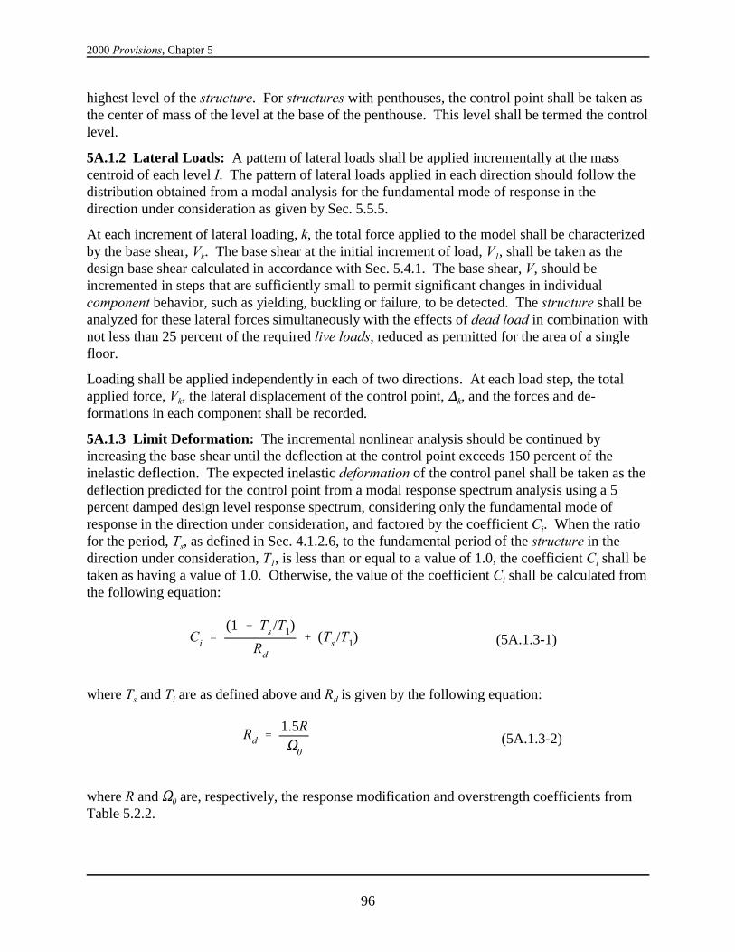
2000 Provisions, Chapter 5
96
Ci '(1 & Ts /T1)
Rd
% (Ts /T1) (5A.1.3-1)
Rd '1.5RS0
(5A.1.3-2)
highest level of the structure. For structures with penthouses, the control point shall be taken asthe center of mass of the level at the base of the penthouse. This level shall be termed the controllevel.
5A.1.2 Lateral Loads: A pattern of lateral loads shall be applied incrementally at the masscentroid of each level I. The pattern of lateral loads applied in each direction should follow thedistribution obtained from a modal analysis for the fundamental mode of response in thedirection under consideration as given by Sec. 5.5.5.
At each increment of lateral loading, k, the total force applied to the model shall be characterizedby the base shear, Vk. The base shear at the initial increment of load, V1, shall be taken as thedesign base shear calculated in accordance with Sec. 5.4.1. The base shear, V, should beincremented in steps that are sufficiently small to permit significant changes in individualcomponent behavior, such as yielding, buckling or failure, to be detected. The structure shall beanalyzed for these lateral forces simultaneously with the effects of dead load in combination withnot less than 25 percent of the required live loads, reduced as permitted for the area of a singlefloor.
Loading shall be applied independently in each of two directions. At each load step, the totalapplied force, Vk, the lateral displacement of the control point, )k, and the forces and de-formations in each component shall be recorded.
5A.1.3 Limit Deformation: The incremental nonlinear analysis should be continued byincreasing the base shear until the deflection at the control point exceeds 150 percent of theinelastic deflection. The expected inelastic deformation of the control panel shall be taken as thedeflection predicted for the control point from a modal response spectrum analysis using a 5percent damped design level response spectrum, considering only the fundamental mode ofresponse in the direction under consideration, and factored by the coefficient Ci. When the ratiofor the period, Ts, as defined in Sec. 4.1.2.6, to the fundamental period of the structure in thedirection under consideration, T1, is less than or equal to a value of 1.0, the coefficient Ci shall betaken as having a value of 1.0. Otherwise, the value of the coefficient Ci shall be calculated fromthe following equation:
where Ts and Ti are as defined above and Rd is given by the following equation:
where R and S0 are, respectively, the response modification and overstrength coefficients fromTable 5.2.2.

Structural Design Criteria
97
5A.1.4 Design Response Parameters: For each lateral force analyzed, the design responseparameters including interstory drift and member force and deformation shall be taken as thevalue obtained from the analysis at the expected inelastic displacement.
5A.1.4.1 Member Strength: The adequacy of members to resist the load combinations of Sec.5.2.7 need not be evaluated.
Exception: Where the Provisions require the consideration of the special load com-binations of Sec. 5.2.7.1, the value of SEi obtained from the analysis at the expectedinelastic deformation, as calculated from Sec. 5A.1.3, shall be taken in place of thequantity S0QE.
5A.1.4.2 Member Deformation: The adequacy of individual members and their connections towithstand the design deformation values, (i, predicted by the analyses shall be evaluated basedon laboratory test data for similar components. The effects of gravity and other loads on memberdeformation capacity shall be considered in these evaluations. Member deformation shall notexceed two thirds of a value that results in loss of ability to carry gravity loads or that results indeterioration of member strength to less than 67 percent of the peak value.
5A.1.4.3 Interstory Drift: The design interstory drift obtained from the analysis shall notexceed 125 percent of the drift limit specified in Sec. 5.2.8.
5A.1.5 Design Review: When the nonlinear static analysis method is used to design thestructure, a design review of the seismic-force-resisting system and the structural analysis shallbe performed by an independent team of registered design professionals in the appropriatedisciplines and others experienced in seismic analysis methods and the theory and application ofnonlinear seismic analysis and structural behavior under extreme cyclic loads. The design reviewshall include, but not be limited to, the following:
1. Review of any site-specific seismic criteria employed in the analysis including the develop-ment of site-specific spectra.,
2. Review of acceptance criteria used to demonstrate the adequacy of structural elements andsystems to withstand the calculated force and deformation demands togther with thatlaboratory and other data used to substantiate these criteria,
3. Review the preliminary design including the determination of the expected inelastic dis-placement of the structure and the margins remaining beyond these displacements, and
4. Review of the final design of the entire structural system and all supporting analyses.

99
Chapter 6
ARCHITECTURAL, MECHANICAL, ANDELECTRICAL COMPONENTS DESIGN REQUIREMENTS
6.1 GENERAL: This chapter establishes minimum design criteria for architectural,mechanical, electrical, and nonstructural systems, components, and elements permanentlyattached to structures, including supporting structures and attachments (hereinafter referred to as"components"). The design criteria establish minimum equivalent static force levels and relativedisplacement demands for the design of components and their attachments to the structure,recognizing ground motion and structural amplification, component toughness and weight, andperformance expectations.
This chapter also establishes minimum seismic design force requirements for nonbuildingstructures that are supported by other structures. Seismic design requirements for nonbuildingstructures that are supported at grade are prescribed in Chapter 14. However, the minimumseismic design forces for nonbuilding structures that are supported by another structure shall bedetermined in accordance with the requirements of Sec. 6.1.3 with Rp equal to the value of Rspecified in Chapter 14 and ap = 2.5 for nonbuilding structures with flexible dynamiccharacteristics and ap = 1.0 for nonbuilding structures with rigid dynamic characteristics. Thedistribution of lateral forces for the supported nonbuilding structure and all nonforcerequirements specified in Chapter 14 shall apply to supported nonbuilding structures.
Exception: For structures in Seismic Design Categories D, E and F if the combinedweight of the supported components and nonbuilding structures with flexible dynamiccharacteristics exceeds 25 percent of the weight of the structure, the structure shall bedesigned considering interaction effects between the structure and the supported items.
Seismic Design Categories for structures are defined in Sec. 4.2. For the purposes of thischapter, components shall be considered to have the same Seismic Design Category as that of the structure that they occupy or to which they are attached unless otherwise noted.
In addition, all components are assigned a component importance factor (Ip) in this chapter. Thedefault value for Ip is 1.00 for typical components in normal service. Higher values for Ip areassigned for components that contain hazardous substances, must have a higher level ofassurance of function, or otherwise require additional attention because of their life-safetycharacteristics. Component importance factors are prescribed in Sec. 6.1.5.
All architectural, mechanical, electrical, and other nonstructural components in structures shallbe designed and constructed to resist the equivalent static forces and displacements determined inaccordance with this chapter. The design and evaluation of support structures and architecturalcomponents and equipment shall consider their flexibility as well as their strength.
Exception: The following components are exempt from the requirements of this chapter:
2000 Provisions, Chapter 6
100
1. All components in Seismic Design Category A,
2. Architectural components in Seismic Design Category B other than parapetssupported by bearing walls or shear walls when the importance factor (Ip) is equal to1.00,
3. Mechanical and electrical components in Seismic Design Category B,
4. Mechanical and electrical components in Seismic Design Category C when theimportance factor (Ip) is equal to 1.00,
5. Mechanical and electrical components in Seismic Design Categories D, E, and Fwhere Ip= 1.0 and flexible connections between the components and associatedductwork, piping, and conduit are provided or that are mounted at 4 ft (1.22 m) or lessabove a floor level and weigh 400 lb (1780 N) or less, or
6. Mechanical and electrical components in Seismic Design Categories C, D, E, and Fwhere Ip= 1.0 and flexible connections between the components and associatedductwork, piping, and conduit are provided that weigh 20 lb (95 N) or less or, fordistribution systems, weight 5 lb/ft (7 N/m) or less.
The functional and physical interrelationship of components and their effect on each other shallbe considered so that the failure of an essential or nonessential architectural, mechanical, orelectrical component shall not cause the failure of an essential architectural, mechanical, orelectrical component.
6.1.1 References and Standards:
6.1.1.1 Consensus Standards: The following references are consensus standards and are to beconsidered part of these provisions to the extent referred to in this chapter:
ASME A17.1 American Society of Mechanical Engineers (ASME), ASMEA17.1, Safety Code For Elevators And Escalators, 1996.
ASTM C635 American Society For Testing And Materials (ASTM), ASTMC635, Standard Specification for the Manufacture,Performance, and Testing of Metal Suspension Systems forAcoustical Tile and Lay-in Panel Ceilings, 1997.
ASME/BPV American Society of Mechanical Engineers (ASME/BPV), Boiler andPressure Vessel Code, including addendums through 2000.
ASTM C636 American Society for Testing and Materials (ASTM), ASTMC636, Standard Practice for Installation of Metal CeilingSuspension Systems for Acoustical Tile and Lay-in Panels,1996.
Architectural, Mechanical, and Electrical Components Design Requirements
101
ANSI/ASME B31.1 American National Standards Institute/American Society ofMechanical Engineers, ANSI/ASME B31.1-98, Power Piping
ANSI/ASME B31.3 American National Standards Institute/American Society ofMechanical Engineers, ANSI/ASME B31.3-96, Process Piping
ANSI/ASME B31.4 American National Standards Institute/American Society ofMechanical Engineers, ANSI/ASME B31.4-92, Liquid TransportationSystems for Hydrocarbons, Liquid Petroleum Gas, AnhydrousAmmonia, and Alcohols
ANSI/ASME B31.5 American National Standards Institute/American Society ofMechanical Engineers, ANSI/ASME B31.5-92, Refrigeration Piping
ANSI/ASME B31.8 American National Standards Institute/American Society ofMechanical Engineers, ANSI/ASME B31.8-95, Gas Transmission andDistribution Piping Systems
ANSI/ASME B31.9 American National Standards Institute/American Society ofMechanical Engineers, ANSI/ASME B31.9-96, Building ServicesPiping
ANSI/ASME B.31.11 American National Standards Institute/American Society ofMechanical Engineers, ANSI/ASME B31.11-89 (Reaffirmed, 1998),Slurry Transportation Piping Systems
NFPA-13 National Fire Protection Association (NFPA), NFPA-13, Standard forthe Installation of Sprinkler Systems, 1999.
IEEE- 344 Institute of Electrical and Electronic Engineers (IEEE). Standard 344,Recommended Practice for Seismic Qualification of Class I EEquipment for Nuclear Power Generating Stations, 1987.
6.1.1.2 Accepted Standards: The following references are standards developed within theindustry and represent acceptable procedures for design and construction:
ASHRAE SRD American Society of Heating, Ventilating, and Air Conditioning(ASHRAE), Handbook, “Seismic Restraint Design,”1999.
CISCA Recs./Zones 0-2 Ceilings and Interior Systems Construction Association (CISCA),Recommendations for Direct-Hung Acoustical Tile and Lay-in PanelCeilings, Seismic Zones 0-2, 1991.
CISCA Recs/ Zones 3-4 Ceilings and Interior Systems Construction Association (CISCA),Recommendations for Direct-Hung Acoustical Tile and Lay-in PanelCeilings, Seismic Zones 3-4, 1991.
SMACNA HVAC Sheet Metal and Air Conditioning Contractors National Association(SMACNA), HVAC Duct Construction Standards, Metal and Flexible,1995.
2000 Provisions, Chapter 6
102
Fp '0.4ap SDS Wp
Rp
Ip
1 % 2zh (6.1.3-1)
Fp ' 1.6SDS Ip Wp (6.1.3-2)
Fp ' 0.3SDS Ip Wp (6.1.3-3)
SMACNA Rectangular Sheet Metal and Air Conditioning Contractors National Association(SMACNA), Rectangular Industrial Duct Construction Standards,1980.
SMACNA Restraint Sheet Metal and Air Conditioning Contractors National Association(SMACNA), Seismic Restraint Manual Guidelines for MechanicalSystems, 1991, including Appendix B, 1998.
AAMA 501.4 American Architectural Manufacturers Association (AAMA),Recommended Static Test Method for Evaluating Curtain Wall andStorefront Systems Subjected to Seismic and Wind Induced InterstoryDrifts. Publication No. AAMA 501.4-2000.
6.1.2 Component Force Transfer: Components shall be attached such that the componentforces are transferred to the structure. Component seismic attachments shall be bolted, welded,or otherwise positively fastened without consideration of frictional resistance produced by theeffects of gravity. A continuous load path of sufficient strength and stiffness between thecomponent and the supporting structure shall be verified. Local elements of the supportingstructure shall be verified for the component forces where they control the design of the elementsor their connections. The component forces shall be those determined in Section 6.1.3, exceptthat modifications to Fp and Rp due to anchorage conditions need not be considered. The designdocuments shall include sufficient information relating to the attachments to verify compliancewith the requirements of these provisions.
6.1.3 Seismic Forces: Seismic forces (Fp) shall be determined in accordance with Eq. 6.1.3-1:
Fp is not required to be taken as greater than:
and Fp shall not be taken as less than:
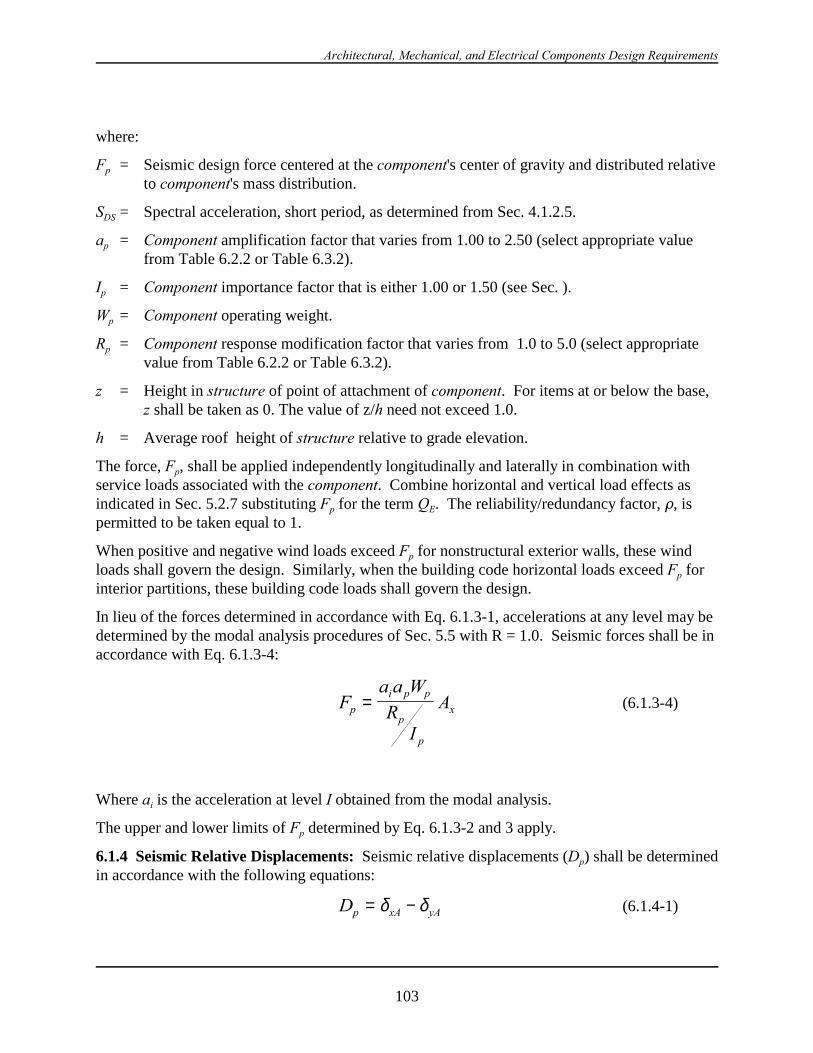
Architectural, Mechanical, and Electrical Components Design Requirements
103
where:
Fp = Seismic design force centered at the component's center of gravity and distributed relativeto component's mass distribution.
SDS = Spectral acceleration, short period, as determined from Sec. 4.1.2.5.
ap = Component amplification factor that varies from 1.00 to 2.50 (select appropriate valuefrom Table 6.2.2 or Table 6.3.2).
Ip = Component importance factor that is either 1.00 or 1.50 (see Sec. ).
Wp = Component operating weight.
Rp = Component response modification factor that varies from 1.0 to 5.0 (select appropriatevalue from Table 6.2.2 or Table 6.3.2).
z = Height in structure of point of attachment of component. For items at or below the base,z shall be taken as 0. The value of z/h need not exceed 1.0.
h = Average roof height of structure relative to grade elevation.
The force, Fp, shall be applied independently longitudinally and laterally in combination withservice loads associated with the component. Combine horizontal and vertical load effects asindicated in Sec. 5.2.7 substituting Fp for the term QE. The reliability/redundancy factor, D, ispermitted to be taken equal to 1.
When positive and negative wind loads exceed Fp for nonstructural exterior walls, these windloads shall govern the design. Similarly, when the building code horizontal loads exceed Fp forinterior partitions, these building code loads shall govern the design.
In lieu of the forces determined in accordance with Eq. 6.1.3-1, accelerations at any level may bedetermined by the modal analysis procedures of Sec. 5.5 with R = 1.0. Seismic forces shall be inaccordance with Eq. 6.1.3-4:
(6.1.3-4)Fa a W
RI
Ap
i p p
p
p
x=
Where ai is the acceleration at level I obtained from the modal analysis.
The upper and lower limits of Fp determined by Eq. 6.1.3-2 and 3 apply.
6.1.4 Seismic Relative Displacements: Seismic relative displacements (Dp) shall be determinedin accordance with the following equations:
(6.1.4-1)Dp xA yA= −δ δ
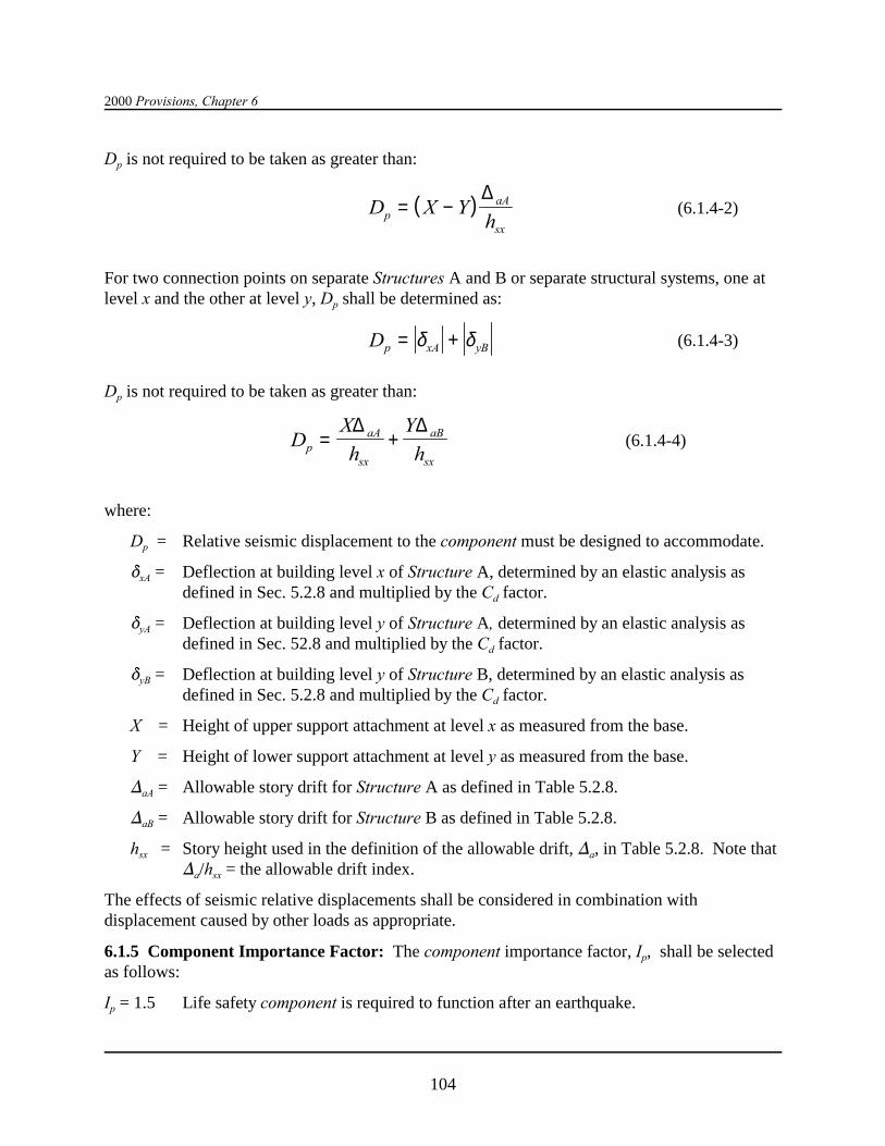
2000 Provisions, Chapter 6
104
Dp is not required to be taken as greater than:
(6.1.4-2)( )D X Yhp
aA
sx
= −∆
For two connection points on separate Structures A and B or separate structural systems, one atlevel x and the other at level y, Dp shall be determined as:
(6.1.4-3)Dp xA yB= +δ δ
Dp is not required to be taken as greater than:
(6.1.4-4)DX
h
Y
hpaA
sx
aB
sx
= +∆ ∆
where:
Dp = Relative seismic displacement to the component must be designed to accommodate.
*xA = Deflection at building level x of Structure A, determined by an elastic analysis asdefined in Sec. 5.2.8 and multiplied by the Cd factor.
*yA = Deflection at building level y of Structure A, determined by an elastic analysis asdefined in Sec. 52.8 and multiplied by the Cd factor.
*yB = Deflection at building level y of Structure B, determined by an elastic analysis asdefined in Sec. 5.2.8 and multiplied by the Cd factor.
X = Height of upper support attachment at level x as measured from the base.
Y = Height of lower support attachment at level y as measured from the base.
)aA = Allowable story drift for Structure A as defined in Table 5.2.8.
)aB = Allowable story drift for Structure B as defined in Table 5.2.8.
hsx = Story height used in the definition of the allowable drift, )a, in Table 5.2.8. Note that)a/hsx = the allowable drift index.
The effects of seismic relative displacements shall be considered in combination withdisplacement caused by other loads as appropriate.
6.1.5 Component Importance Factor: The component importance factor, Ip, shall be selectedas follows:
Ip = 1.5 Life safety component is required to function after an earthquake.
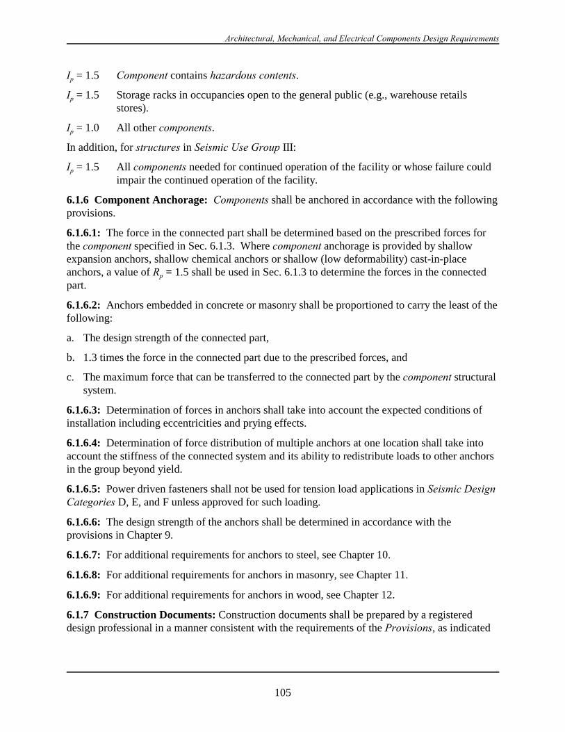
Architectural, Mechanical, and Electrical Components Design Requirements
105
Ip = 1.5 Component contains hazardous contents.
Ip = 1.5 Storage racks in occupancies open to the general public (e.g., warehouse retailsstores).
Ip = 1.0 All other components.
In addition, for structures in Seismic Use Group III:
Ip = 1.5 All components needed for continued operation of the facility or whose failure couldimpair the continued operation of the facility.
6.1.6 Component Anchorage: Components shall be anchored in accordance with the followingprovisions.
6.1.6.1: The force in the connected part shall be determined based on the prescribed forces forthe component specified in Sec. 6.1.3. Where component anchorage is provided by shallowexpansion anchors, shallow chemical anchors or shallow (low deformability) cast-in-placeanchors, a value of Rp = 1.5 shall be used in Sec. 6.1.3 to determine the forces in the connectedpart.
6.1.6.2: Anchors embedded in concrete or masonry shall be proportioned to carry the least of thefollowing:
a. The design strength of the connected part,
b. 1.3 times the force in the connected part due to the prescribed forces, and
c. The maximum force that can be transferred to the connected part by the component structuralsystem.
6.1.6.3: Determination of forces in anchors shall take into account the expected conditions ofinstallation including eccentricities and prying effects.
6.1.6.4: Determination of force distribution of multiple anchors at one location shall take intoaccount the stiffness of the connected system and its ability to redistribute loads to other anchorsin the group beyond yield.
6.1.6.5: Power driven fasteners shall not be used for tension load applications in Seismic DesignCategories D, E, and F unless approved for such loading.
6.1.6.6: The design strength of the anchors shall be determined in accordance with theprovisions in Chapter 9.
6.1.6.7: For additional requirements for anchors to steel, see Chapter 10.
6.1.6.8: For additional requirements for anchors in masonry, see Chapter 11.
6.1.6.9: For additional requirements for anchors in wood, see Chapter 12.
6.1.7 Construction Documents: Construction documents shall be prepared by a registereddesign professional in a manner consistent with the requirements of the Provisions, as indicated
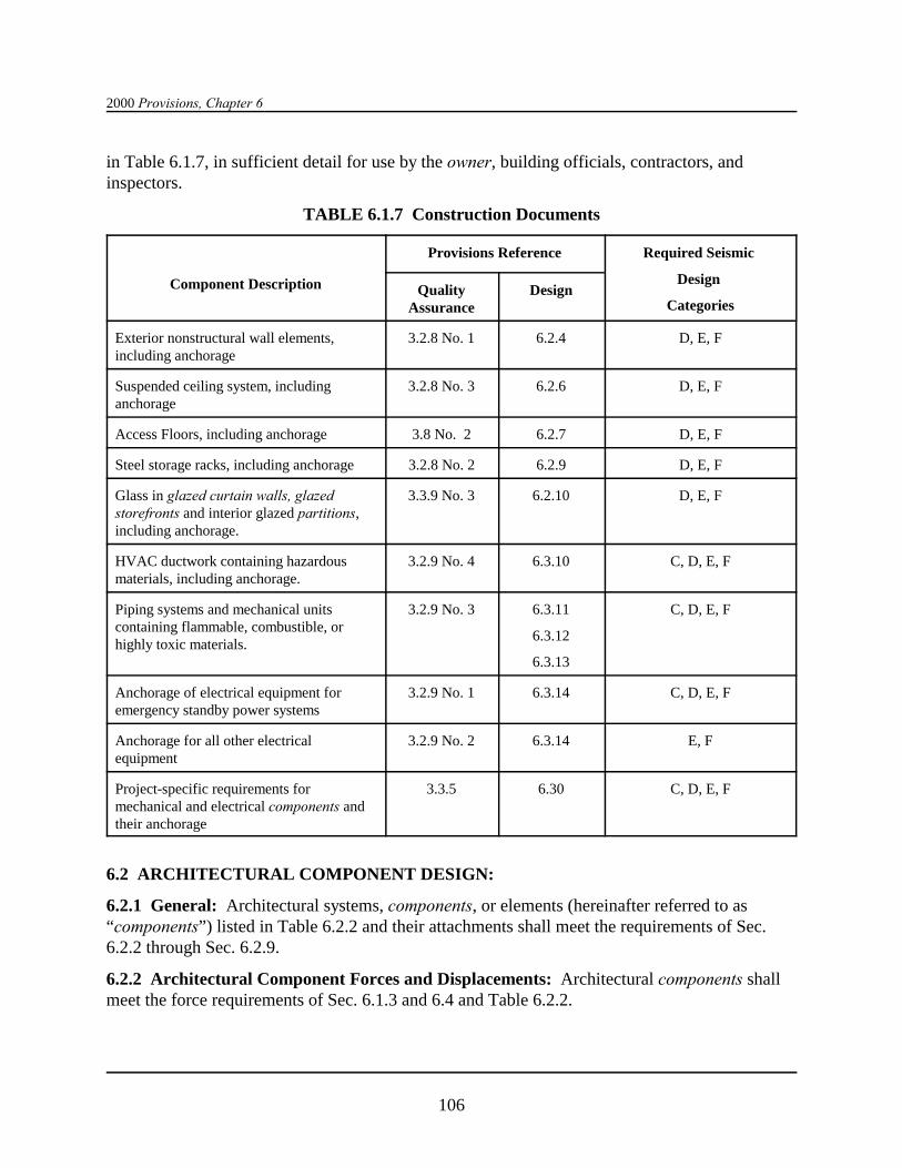
2000 Provisions, Chapter 6
106
in Table 6.1.7, in sufficient detail for use by the owner, building officials, contractors, andinspectors.
TABLE 6.1.7 Construction Documents
Component Description
Provisions Reference Required Seismic
Design
CategoriesQuality
AssuranceDesign
Exterior nonstructural wall elements,including anchorage
3.2.8 No. 1 6.2.4 D, E, F
Suspended ceiling system, includinganchorage
3.2.8 No. 3 6.2.6 D, E, F
Access Floors, including anchorage 3.8 No. 2 6.2.7 D, E, F
Steel storage racks, including anchorage 3.2.8 No. 2 6.2.9 D, E, F
Glass in glazed curtain walls, glazedstorefronts and interior glazed partitions,including anchorage.
3.3.9 No. 3 6.2.10 D, E, F
HVAC ductwork containing hazardousmaterials, including anchorage.
3.2.9 No. 4 6.3.10 C, D, E, F
Piping systems and mechanical unitscontaining flammable, combustible, orhighly toxic materials.
3.2.9 No. 3 6.3.11
6.3.12
6.3.13
C, D, E, F
Anchorage of electrical equipment foremergency standby power systems
3.2.9 No. 1 6.3.14 C, D, E, F
Anchorage for all other electricalequipment
3.2.9 No. 2 6.3.14 E, F
Project-specific requirements formechanical and electrical components andtheir anchorage
3.3.5 6.30 C, D, E, F
6.2 ARCHITECTURAL COMPONENT DESIGN:
6.2.1 General: Architectural systems, components, or elements (hereinafter referred to as“components”) listed in Table 6.2.2 and their attachments shall meet the requirements of Sec.6.2.2 through Sec. 6.2.9.
6.2.2 Architectural Component Forces and Displacements: Architectural components shallmeet the force requirements of Sec. 6.1.3 and 6.4 and Table 6.2.2.
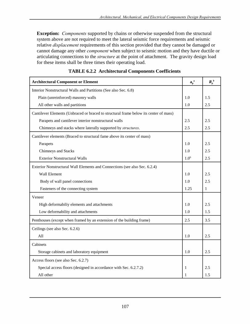
Architectural, Mechanical, and Electrical Components Design Requirements
107
Exception: Components supported by chains or otherwise suspended from the structuralsystem above are not required to meet the lateral seismic force requirements and seismicrelative displacement requirements of this section provided that they cannot be damaged orcannot damage any other component when subject to seismic motion and they have ductile orarticulating connections to the structure at the point of attachment. The gravity design loadfor these items shall be three times their operating load.
TABLE 6.2.2 Architectural Components Coefficients
Architectural Component or Element apa Rp
b
Interior Nonstructural Walls and Partitions (See also Sec. 6.8)
Plain (unreinforced) masonry walls
All other walls and partitions
1.0
1.0
1.5
2.5
Cantilever Elements (Unbraced or braced to structural frame below its center of mass)
Parapets and cantilever interior nonstructural walls
Chimneys and stacks where laterally supported by structures.
2.5
2.5
2.5
2.5
Cantilever elements (Braced to structural fame above its center of mass)
Parapets
Chimneys and Stacks
Exterior Nonstructural Walls
1.0
1.0
1.0b
2.5
2.5
2.5
Exterior Nonstructural Wall Elements and Connections (see also Sec. 6.2.4)
Wall Element
Body of wall panel connections
Fasteners of the connecting system
1.0
1.0
1.25
2.5
2.5
1
Veneer
High deformabiliy elements and attachments
Low deformability and attachments
1.0
1.0
2.5
1.5
Penthouses (except when framed by an extension of the building frame) 2.5 3.5
Ceilings (see also Sec. 6.2.6)
All 1.0 2.5
Cabinets
Storage cabinets and laboratory equipment 1.0 2.5
Access floors (see also Sec. 6.2.7)
Special access floors (designed in accordance with Sec. 6.2.7.2)
All other
1
1
2.5
1.5

2000 Provisions, Chapter 6
108
Appendages and Ornamentations 2.5 2.5
Signs and Billboards 2.5 2.5
Other Rigid Components
High deformability elements and attachments
Limited deformability elements and attachments
Low deformability elements and attachments
1.0
1.0
1.0
3.5
2.5
1.5
Other flexible components
High deformability elements and attachments
Limited deformability elements and attachments
Low deformability elements and attachments
2.5
2.5
2.5
3.5
2.5
1.5a A lower value for ap may be justified by detailed dynamic analysis. The value for ap shall not beless than 1.00. The value of ap = 1 is for equipment generally regarded as rigid and rigidly attached. The value of ap = 2.5 is for flexible components or flexibility attached components. See Chapter 2for definitions of rigid flexible components including attachments.
b Where flexible diaphragms provide lateral support for walls and partitions, the design forces foranchorage to the diaphragm shall be specified in Sec. 5.2.5.
6.2.3 Architectural Component: Architectural components that could pose a life-safety hazardshall be designed for the seismic relative displacement requirements of Sec. 6.1.4. Architecturalcomponents shall be designed for vertical deflection due to joint rotation of cantilever structuralmembers.
6.2.4 Exterior Nonstructural Wall Elements and Connections:
6.2.4.1 General: Exterior nonstructural wall panels or elements that are attached to or enclosethe structure shall be designed to resist the forces in accordance with Eq. 6.1.3-1 or 6.1.3-2 andshall accommodate movements of the structure resulting from response to the design basisground motion, Dp, or temperature changes. Such elements shall be supported by means ofpositive and direct structural supports or by mechanical connections and fasteners in accordancewith the following requirements:
a. Connections and panel joints shall allow for a relative movement between stories for not lessthan the calculated story drift Dp or ½ in. (13 mm), whichever is greater..
b. Connections to permit movement in the plane of the panel for story drift shall be slidingconnections using slotted or oversize holes, connections that permit movements by bendingof steel, or other connections that provide equivalent sliding or ductile capacity.
c. Bodies of connectors shall have sufficient deformability and rotation capacity to precludefracture of the concrete of low deformation failures at or near welds.
Architectural, Mechanical, and Electrical Components Design Requirements
109
d. All fasteners in the connecting system such as bolts, inserts, welds, and dowels and the bodyof the connectors shall be designed for the force, Fp, determined in by Eq. 6.1.3-2 withvallues of Rp and ap taken from Table 6.2.2 applied at the center of mass of the panel.
e. Anchorage using flat straps embedded in concrete or masonry shall be attached to or hookedaround reinforcing steel or otherwise terminated so as to effectively transfer forces to thereinforcing steel.
6.2.4.2 Glass: Glass is a glazed curtain walls and storefronts shall be designed and installed inaccordance with sec. 6.2.10.
6.2.5 Out-of-Plane-Bending: Transverse or out-of-plane bending or deformation of acomponent or system that is subjected to forces as determined in Sec. 6.1.3 shall not exceed thedeflection capacity of the component or system.
6.2.6 Suspended Ceilings: Suspended ceilings shall be designed to meet the seismic forcerequirements of Sec. 6.2.6.1. In addition, suspended ceilings shall meet the requirements ofeither Industry Standard Construction as modified in Sec. 6.2.6.2 or integral construction asspecified in Sec. 6.2.6.3.
6.2.6.1 Seismic Forces: Suspended ceilings shall be designed to meet the force requirements ofSec. 6.1.3.
The weight of the ceiling, Wp, shall include the ceiling grid and panels; light fixtures if attachedto, clipped to, or laterally supported by the ceiling grid; and other components that are laterallysupported by the ceiling. Wp shall be taken as not less than 4 psf (19 N/m2).
The seismic force, Fp, shall be transmitted through the ceiling attachments to the buildingstructural elements or the ceiling-structure boundary.
Design of anchorage and connections shall be in accordance with these provisions.
6.2.6.2 Industry Standard Construction: Unless designed in accordance with Sec. 6.2.6.3,suspended ceilings shall be designed and constructed in accordance with this section.
6.2.6.2.1 Seismic Design Category C: Suspended ceilings in Seismic Design Category C shallbe designed and installed in accordance with CISCA Rec for Zones 0-2, except that seismicforces shall be determined in accordance with Sec. 6.1.3 and 6.2.6.1.
Sprinkler heads and other penetrations in Seismic Design Category C shall have a minimum of1/4 inch (6 mm) clearance on all sides.
6.2.6.2.2 Seismic Design Categories D, E, and F: Suspended ceilings in Seismic DesignCategories D, E, and F be designed and installed in accordance with CISCA Rec for Zones 3-4and the additional requirements listed in this subsection.
a. A heavy duty T-bar grid system shall be used.
b. The width of the perimeter supporting closure angle shall be not less than 2 in. (50 mm). Ineach orthogonal horizontal direction, one end of the ceiling grid shall be attached to the
2000 Provisions, Chapter 6
110
closure angle. The other end in each horizontal direction shall have a 3/4 in. (19 mm)clearance from the wall and shall rest upon and be free to slide on a closure angle.
c. For ceiling areas exceeding 1000 ft2 (92.9 m2), horizontal restraint of the ceiling to thestructural system shall be provided. The tributary areas of the horizontal restraints shall beapproximately equal.
Exception: Rigid braces are permitted to be used instead of diagonal splaywires. Braces the attachments to the structural system above shall be adequateto limit relative lateral deflections at point of attachment of ceiling grid to lessthan 1/4 in. (6 mm) for the loads prescribed in Sec. 6.1.3.
d. For ceiling areas exceeding 2500 ft2 (232 m2), a seismic separation joint or full heightpartition that breaks the ceiling up into areas not exceeding 2500 ft2 shall be provided unlessstructural analyses are performed of the ceiling bracing system for the prescribed seismicforces which demonstrate ceiling system penetrations and closure angles provide sufficientclearance to accommodate the additional movement. Each areas shall be provided withclosure angles in accordance with Item b and horizontal restraints or bracing in accordancewith Item c.
e. Except where rigid braces are used to limit lateral deflections, sprinkler heads and otherpenetrations shall have a 2 in. (50 mm) oversize ring, sleeve, or adapter through the ceilingtile to allow for free movement of at least 1 in. (25 mm) in all horizontal directions. Alternatively, a swing joint can accommodate 1 in. (25 mm) of ceiling movements in allhorizontal directions are permitted to be provided at the top of the sprinkler head extension.
f. Changes in ceiling plan elevation shall be provided with positive bracing.
g. Cable trays and electrical conduits shall be supported independently of the ceiling.
h. Suspended ceilings shall be subject to the special inspection requirements of Sec. 3.3.9 of theProvisions.
6.2.6.3 Integral Ceiling/Sprinkler Construction: As a alternative to providing largeclearances around sprinkler system penetrations through ceiling systems, the sprinkler system andceiling grid are permitted to be designed and tied together as an integral unit. Such a design shallconsider the mass and flexibility of all elements involved, including: ceiling system, sprinklersystem, light fixtures, and mechanical (HVAC) appurtenances. The design shall be performed bya registered design professional.
6.2.7 Access Floors:
6.2.7.1 General: Access floors shall be designed to meet the force provisions of Sec. 6.1.3 andthe additional provisions of this section. The weight of the access floor, Wp, shall include theweight of the floor system, 100 percent of the weight of all equipment fastened to the floor, and25 percent of the weight of all equipment supported by but not fastened to the floor. The seismicforce, Fp, shall be transmitted from the top surface of the access floor to the supporting structure.

Architectural, Mechanical, and Electrical Components Design Requirements
111
Overturning effects of equipment fastened to the access floor panels also shall be considered. The ability of “slip on” heads for pedestals shall be evaluated for suitability to transferoverturning effects of equipment.
When checking individual pedestals for overturning effects, the maximum concurrent axial loadshall not exceed the portion of Wp assigned to the pedestal under construction.
6.2.7.2 Special Access Floors: Access floors shall be considered to be “special access floors” ifthey are designed to comply with the following considerations:
1. Connections transmitting seismic loads consist of mechanical fasteners, concrete anchors,welding, or bearing. Design load capacities comply with recognized design codes and/orcertified test results.
2. Seismic loads are not transmitted by friction produced solely by the effects of gravity,powder-actuated fasteners (shot pins), or adhesives.
3. The bracing system shall be designed considering the destabilizing effects of individualmembers buckling in compression.
4. Bracing and pedestals are of structural or mechanical shape produced to ASTM specificationsthat specify minimum mechanical properties. Electrical tubing shall be used.
5. Floor stingers that are designed to carry axial seismic loads that are mechanically fastened tothe supporting pedestals are used.
6.2.8 Partitions:
6.2.8.1 General: Partitions that are tied to the ceiling and all partitions greater than 6 ft (1.8 m)in height shall be laterally braced to the building structure. Such bracing shall be independent o fany ceiling splay bracing. Bracing shall be spaced to limit horizontal deflection at the partitionhead to comparable with ceiling deflection requirements as determined in Sec. 6.2.6 forsuspended ceilings and Sec. 6.2.2 for other systems.
6.2.8.2 Glass: Glass in glazed partitions shall be designed and installed in accordance with Sec.6.2.10.
6.2.9 Steel Storage Racks: Steel storage racks shall be designed to meet the force requirementsof Chapter 14.
6.2.10 Glass in Glazed Curtain Walls, Glazed Storefronts, and Glazed Partitions:
6.2.10.1 General: Glass in glazed curtain walls, glazed storefronts and glazed partitions shallmeet the relative displacement requirement of Eq. 6.2.10.1-1:
(6.2.10.1-1)fallout pID∆ ≥ 125.
or 0.5 inch (13 mm), whichever is greater, where:
)fallout = the relative seismic displacement (drift) causing glass fallout from thecurtain wall, storefront wall or partition (Section 6.2.10.2).

2000 Provisions, Chapter 6
112
Dp = the relative seismic displacement that the component must be designedto accommodate (Eq. 6.1.4-1). Dp shall be determined over the heightof the glass component under consideration.
I = the occupancy importance factor (Table 1.4).
Exceptions:
1. Glass with sufficient clearances from its frame such that physicalcontact between the glass and frame will not occur at the designdrift, as demonstrated by Eq. 6.2.10.1-2, shall be exempt from theprovisions of Eq. 6.2.10.1-1:
(6.2.10.1-2)D Dclear p≥ 125.
or 0.5 inch (13 mm); whichever is greater, where:
Dclear = 2 11
2
1
ch c
b cp
p
+
hp = the height of the rectangular glass,
bp = the width of the rectangular glass,
c1 = the clearance (gap) between the vertical glass edgesand the frame, and
c2 = the clearance (gap) between the horizontal glassedges and the frame.
2. Fully tempered monolithic glass in Seismic Use Groups I and II located nomore than 10 ft (3 m) above a walking surface shall be exempt from theprovisions of Eq. 6.2.10.1-1.
3. Annealed or heat-strengthened laminated glass in single thickness withinterlayer no less than 0.030 in. (0.76 mm) that is captured mechanically in awall system glazing pocket, and whose perimeter is secured to the frame by awet glazed gunable curing elastomeric sealant perimeter bead of ½ in. (13mm) minimum glass contact width, or other approved anchorage system, shallbe exempt from the provisions of Eq. 6.2.10.1-1.
6.2.10.2 Seismic Drift Limits for Glass Components: )fallout, the drift causing glass falloutfrom the curtain wall, storefront or partition, shall be determined in accordance with SMACNARestraint, or by engineering analysis.

Architectural, Mechanical, and Electrical Components Design Requirements
113
6.3 MECHANICAL AND ELECTRICAL COMPONENT DESIGN:
6.3.1 General: Attachments and equipment supports for the mechanical and electrical systems,components, or elements (hereinafter referred to as “components”) shall meet the requirements ofSec. 6.3.2 through Sec. 6.3.16.
6.3.2 Mechanical and Electrical Component Forces and Displacements: Mechanical andelectrical components shall meet the force and seismic relative displacement requirements of Sec.6.1.3, Sec. 6.1.4, and Table 6.3.2.
Some complex equipment such as valve operators, turbines and generators, and pumps andmotors are permitted to be functionally connected by mechanical links not capable of transferringthe seismic loads or accommodating seismic relative displacements and may require specialdesign considerations such as a common rigid support or skid.
Exception: Components supported by chains or similarly suspended from the structureabove or not required to meet the lateral seismic force requirements and seismic relativedisplacement requirements of this section provided that they cannot be damaged orcannot damage any other component when subject to seismic motion and they have highdeformation or articulating connections to the building at the point of attachment. Thegravity design load for these items shall be three times their operating load.
TABLE 6.3.2 Mechanical and Electrical Components Coefficients
Mechanical and Electrical Component or Elementb apa Rp
General Mechanical
Boilers and Furnaces
Pressure vessels on skirts and free-standing
Stacks
Cantilevered chimneys
Other
1.0
2.5
2.5
2.5
1.0
2.5
2.5
2.5
2.5
2.5
Manufacturing and Process Machinery
General
Conveyors (nonpersonnel)
1.0
2.5
2.5
2.5
Piping Systems
High deformability elements and attachments
Limited deformability elements and attachments
Low deformability elements and attachments
1.0
1.0
1.0
3.5
2.5
1.5
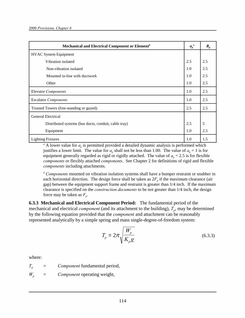
2000 Provisions, Chapter 6
Mechanical and Electrical Component or Elementb apa Rp
114
HVAC System Equipment
Vibration isolated
Non-vibration isolated
Mounted in-line with ductwork
Other
2.5
1.0
1.0
1.0
2.5
2.5
2.5
2.5
Elevator Components 1.0 2.5
Escalator Components 1.0 2.5
Trussed Towers (free-standing or guyed) 2.5 2.5
General Electrical
Distributed systems (bus ducts, conduit, cable tray)
Equipment
2.5
1.0
5
2.5
Lighting Fixtures 1.0 1.5a A lower value for ap is permitted provided a detailed dynamic analysis is performed whichjustifies a lower limit. The value for ap shall not be less than 1.00. The value of ap = 1 is forequipment generally regarded as rigid or rigidly attached. The value of ap = 2.5 is for flexiblecomponents or flexibly attached components. See Chapter 2 for definitions of rigid and flexiblecomponents including attachments.
b Components mounted on vibration isolation systems shall have a bumper restraint or snubber ineach horizontal direction. The design force shall be taken as 2Fp if the maximum clearance (airgap) between the equipment support frame and restraint is greater than 1/4 inch. If the maximumclearance is specified on the construction documents to be not greater than 1/4 inch, the designforce may be taken as Fp.
6.3.3 Mechanical and Electrical Component Period: The fundamental period of themechanical and electrical component (and its attachment to the building), Tp, may be determinedby the following equation provided that the component and attachment can be reasonablyrepresented analytically by a simple spring and mass single-degree-of-freedom system:
(6.3.3)TW
K gp
p
p
= 2π
where:
Tp = Component fundamental period,
Wp = Component operating weight,
Architectural, Mechanical, and Electrical Components Design Requirements
115
g = Gravitational acceleration, and
Kp = Stiffness of resilient support system of the component and attachment, determinedin terms of load per unit deflection at the center of gravity of the component.
Note that consistent units must be used.
Alternatively, determine the fundamental period of the component in seconds, Tp, fromexperimental test data or by a properly substantiated analysis.
6.3.4 Mechanical and Electrical Component Attachments: The stiffness of mechanical andelectrical component attachments shall be designed such that the load path for the componentperforms its intended function.
6.3.5 Component Supports: Mechanical and electrical component supports and the means bywhich they are attached to the component shall be designed for the forces determined in Sec.6.1.3 and in conformance with Chapters 5 though 9, as appropriate, for the materials comprisingthe means of attachment. Such supports include structural members, braces, frames, skirts, legs,saddles, pedestals, cables, guys, stays, snubbers, ans tethers. Component supports may be forgedor cast as a part of the mechanical or electrical component. If standard or proprietary supports areused, they shall be designed by either load rating (i.e., testing) or for the calculated seismicforces. In addition, the stiffness of the support, when appropriate, shall be designed such that theseismic load path for the component performs its intended function.
Component supports shall be designed to accommodate the seismic relative displacementsbetween points of support determined in accordance with Sec. 6.1.4.
In addition, the means by which supports are attached to the component, except when integral(i.e., cast or forged), shall be designed to accommodate both the forces and displacementsdetermined in accordance with Sec. 6.1.3 and 6.1.4. If the value of Ip = 1.5 for the component,the local region of the support attachment point to the component shall be evaluated for the effectof the load transfer on the component wall.
6.3.6 Component Certification: The manufacturer’s certificate of compliance with the forcerequirements of the Provisions shall be submitted to the regulatory agency when required by thecontract documents or when required by the regulatory agency.
6.3.7 Utility and Service Lines at Structure Interfaces: At the interface of adjacent structuresor portions of the same structure that may move independently, utility lines shall be providedwith adequate flexibility to accommodate the anticipated differential movement between theground and the structure. Differential displacement calculations shall be determined inaccordance with Sec. 6.1.4.
6.3.8 Site-Specific Considerations: The possible interruption of utility service shall beconsidered in relation to designated seismic systems in Seismic Use Group III as defined in Sec.1.3.1. Specific attention shall be given to the vulnerability of underground utilities and utilityinterfaces between the structure and the ground in all situations where Site Class E and F soil ispresent and where the seismic coefficient Ca is equal to or greater than 0.15.

2000 Provisions, Chapter 6
116
6.3.9 Storage Tanks:
6.3.9.1 Above-Grade Storage Tanks: For storage tanks mounted above grade in structures,attachments, supports, and the tank shall be designed to meet the force requirements of Chapter14.
6.3.10 HVAC Ductwork: Attachments and supports for HVAC ductwork systems shall bedesigned to meet the force and displacement requirements of Sec. 6.1.3 and 6.1.4 and theadditional requirements of this section. In addition to their attachments and supports, ductworksystems designated as having Ip greater than 1.0 shall be designed to meet the force anddisplacement requirements of Sec. 6.1.3 and 6.1.4 and the additional requirements of this section. Where HVAC ductwork runs between structures that could displace relative to one another andfor isolated structures where the HVAC ductwork crosses the isolation interface, the HVACductwork shall be designed to accommodate the seismic relative displacements specified in Sec.6.1.4.
Seismic restraints are not required for HVAC ducts with Ip = 1.0 if either of the followingconditions are met for the full length of each duct run:
a. HVAC ducts are suspended from hangers, and all hangers are 12 in. (305 mm) or less inlength from the top of the duct to the supporting structure and the hangers are detailed toavoid significant bending of the hangers and their attachments.
or
b. HVAC ducts have a cross-sectional area of less than 6 ft2 (0.557 m2).
HVAC duct systems fabricated and installed in accordance with the SMACNA HVAC,SMACNA Rectangular, and SMACNA Restraint shall be deemed to meet the lateral bracingrequirements of this section.
Equipment items installed in-line with the duct system (e.g., fans, heat exchangers, andhumidifiers) with an operating weight greater than 75 lb (334 N) shall be supported and laterallybraced independently of the duct system and shall meet the force requirements of Sec. 6.1.3. Appurtenances such as dampers, louvers, and diffusers shall be positively attached withmechanical fasteners. Unbraced piping attached to in-line equipment shall be provided withadequate flexibility to accommodate differential displacements.
6.3.11 Piping Systems: Attachments and supports for piping systems shall be designed to meetthe force and displacement requirements of Sec. 6.1.3 and 6.1.4 and the additional requirementsof this section. In addition to their attachments and supports, piping systems designated ashaving Ip greater than 1.0 shall be designed to meet the force and displacement provisions of Sec.6.1.3 and 6.1.4 and the additional requirements of this section. When piping systems areattached to structures that could displace relative to one another and for isolated structures,including foundations, where the piping system crosses the isolation interface, the piping systemshall be designed to accommodate the seismic relative displacements specified in Sec. 6.1.4.
Architectural, Mechanical, and Electrical Components Design Requirements
117
Seismic effects that shall be considered in the design of a piping system include the dynamiceffects of the piping system, its contents, and, when appropriate, its supports. The interactionbetween the piping system and the supporting structures, including other mechanical andelectrical equipment, also shall be considered.
See Sec. 6.3.16 for elevator system piping requirements.
6.3.11.1 Fire Protection Sprinkler Systems: Fire protection sprinkler systems designed andconstructed in accordance with NFPA 13 shall be deemed to meet the force, displacement, andother requirements of this section provided that the seismic design force and displacementcalculated in accordance with NFPA 13, multiplied by a factor of 1.4, is not less than thatdetermined using the Provisions.
6.3.11.2 Other Piping Systems. The following documents have been adopted as nationalstandards by the American National Standards Institute (ANSI) and are appropriate for use in theseismic design of piping systems provided that the seismic design forces and displacements usedare comparable to those determined using the Provisions: ANSI/ASME B31.1, ANSI/ASMEB31.3, ANSI/ASME B31.4, ANSI/ASME B31.5, ANSI/ASME B31.9, ANSI/ASME B31.11, andANSI/ASME 31.8.
Exception: Piping systems designated as having an Ip greater than 1.0 shall not bedesigned using the simplified analysis procedures of ANSI/ASME B31.9, Sec. 919.4.1(a).
The following requirements shall also be met for piping systems designated as having an Ip
greater than 1.0.
a. Under design loads and displacements, piping shall not be permitted to impact other components.
b. Piping shall accommodate the effects of relative displacements that may occur betweenpiping support points on the structure on the ground, other mechanical and/or electricalequipment, and other piping
6.3.11.2.1 Supports and Attachments for Other Piping: In addition to meeting the force,displacement, and other requirements of this section, attachments and supports for piping shall besubject to the following other requirements and limitations.
a. Attachments shall be designed in accordance with Sec. 6.1.6.
b. Seismic supports are not required for:
1. Piping supported by rod hangers provided that all hangers in the pipe run are 12 in.(305 mm) or less in length from the top of the pipe to the supporting structure and thepipe can accommodate the expected deflections. Rod hangers shall not beconstructed in a manner that would subject the rod to bending moments.
2. High deformability piping in Seismic Design Categories D, E, and F designated ashaving Ip greater than 1.0 and a nominal pipe size of 1 in. (25 mm) or less when

2000 Provisions, Chapter 6
118
provisions are made to protect the piping from impact or to avoid the impact of largerpiping or other mechanical equipment.
3. High deformability piping in Seismic Design Category C designated as having an Ip
greater than 1.0 and a nominal pipe size of 2 in. (51 mm) or less when provisions aremade to protect the piping from impact or to avoid the impact of larger piping or othermechanical equipment.
4. High deformability piping in Seismic Design Categories D, E, and F designated ashaving an Ip equal to 1.0 and a nominal pipe size of 3 in. (76 mm) or less.
c. Seismic supports shall be constructed so that support engagement is maintained.
6.3.12 Boilers and Pressure Vessels: Attachments and supports for boilers and pressurevessels shall be designed to meet the force and displacement provisions of Sec. 6.1.3 and 6.1.4and the additional provisions of this section. In addition to their attachments and supports,boilers and pressure vessels designated as having an Ip = 1.5 themselves shall be designed tomeet the force and displacement provisions of Sec. 6.1.3 and 6.1.4.
Seismic effects that shall be considered in the design of a boiler or pressure vessel include thedynamic effects of the boiler or pressure vessel and it supports, sloshing of liquid contents, loadsfrom attached components such as piping, and the interaction between the boiler or pressurevessel and its support.
6.3.12.1 ASME Boilers and Pressure Vessels: Boilers or pressure vessels designed inaccordance with ANSI/ASME B31.9 shall be deemed to meet the force, displacement, and otherrequirements of this section. In lieu of the specific force and displacement provisions providedin the ASME code, the force and displacement provisions of Sec. 6.1.3 and 6.1.4 shall be used.
6.3.12.2 Other Boilers and Pressure Vessels: Boilers and pressure vessels designated ashaving an Ip = 1.5 but not constructed in accordance with the provisions of ANSI/ASME B31.9shall meet the following provisions:
a. The design strength for seismic loads of combination with other service loads and appropriateenvironmental effects shall not exceed the following:
(1) For boilers and pressure vessels constructed with ductile materials (e.g., steelaluminum or copper), 90 percent of the material minimum specified yield strength .
(2) For threaded connections in boilers or pressure vessels or their supports constructedwith ductile materials, 70 percent of the material minimum specified yield strength.
(3) For boilers and pressure vessels constructed with nonductile materials (e.g., plastic,cast iron, or ceramics), 25 percent of the material minimum specified tensile strength.
(4) For threaded connections in boilers or pressures vessels or their supports constructedwith nonductile materials, 20 percent of the material minimum specified tensilestrength.

Architectural, Mechanical, and Electrical Components Design Requirements
119
b. Provisions shall be made to mitigate seismic impact for boiler and pressure vesselcomponents constructed of nonductile materials or in cases where material ductility isreduced (e.g., low temperature applications).
c. Boilers and pressure vessels shall be investigated to ensure that the interaction effectsbetween them and other constructions are acceptable.
6.3.12.3 Supports and Attachments for Boilers and Pressure Vessels: Attachments andsupports for boilers and pressure vessels shall meet the following provisions:
a. Attachments and supports transferring seismic loads shall be constructed of materials suitablefor the application and designed and constructed in accordance with nationally recognizedstructural code such as, when constructed of steel, AISC LRFD and AISC ASD (see Chapter8 for full references).
b. Attachments embedded in concrete shall be suitable for cyclic loads.
c. Seismic supports shall be constructed so that support engagement is maintained.
6.3.13 Mechanical Equipment Attachments and Supports: Attachments and supports formechanical equipment not covered in Sec. 6.3.8 through 6.3.12 or 6.3.16 shall be designed tomeet the force and displacement requirements of Sec. 6.1.3 and 6.1.4 and the additionalrequirements of this section. In addition, mechanical equipment designated as having an Ip
greater than 1.0 shall be designed to meet the force and displacement requirements of Sec. 6.1.3and 6.1.4 and the additional requirements of this section.
When required, seismic effects that shall be considered in the design of mechanical equipment,attachments and their supports include dynamic effects of the equipment, its contents, and whenappropriate its supports. The interaction between the equipment and the supporting structures,including other mechanical and electrical equipment, also shall be considered.
6.3.13.1 Mechanical Equipment: Mechanical equipment having an Ip greater than 1.0 shallmeet the following requirements:
a. Provisions shall be made to eliminate seismic impact for equipment components vulnerableto impact, equipment components constructed of nonductile materials, and in cases wherematerial ductility is reduced (e.g., low temperature applications).
b. The possibility for loadings imposed on the equipment by attached utility or service lines dueto differential motions of points of support from separate structures shall be evaluated.
In addition, components of mechanical equipment designated as having an Ip greater than 1.0 andcontaining sufficient material that would be hazardous if released shall be designed for seismicloads. The design strength for seismic loads in combination with other service loads andappropriate environmental effects such as corrosion shall be based on the following:
a. For mechanical equipment constructed with ductile materials (e.g., steel, aluminum, orcopper), 90 percent of the equipment material minimum specified yield strength.
2000 Provisions, Chapter 6
120
b. For threaded connections in equipment constructed with ductile materials, 70 percent of thematerial minimum specified yield strength.
c. For mechanical equipment constructed with nonductile materials (e.g., plastic, cast iron, orceramics), 25 percent of the equipment material minimum tensile strength.
d. For threaded connections in equipment constructed with nonductile, 20 percent of thematerial minimum specified yield strength.
6.3.13.2 Attachments and Supports for Mechanical Equipment: Attachments and supportsfor mechanical equipment shall meet the following requirements:
a. Attachments and supports transferring seismic loads shall be constructed of materials suitablefor the application and designated and constructed in accordance with a nationally recognizedstandard specification such as, when constructed of steel, AISC LRFD and AISC ASD.
b. Friction clips shall not be used for anchorage attachment.
c. Expansion anchors shall not be used for non-vibration isolated mechanical equipment ratedover 10 hp (7.45 kW).
Exception: Undercut expansion anchors are permitted.
d. Supports shall be specifically evaluated if weak-axis bending of cold-formed support steel isrelied on for the seismic load path.
e. Components mounted on vibration isolation systems shall have a bumper restraint or snubberin each horizontal direction, and vertical restraints shall be provided where required to resistoverturning. Isolator housings and restraints shall be constructed of ductile materials. (Seeadditional design force requirements in Table 6.3.2.) A viscoelastic pad or similar materialof appropriate thickness shall be used between the bumper and equipment item to limit theimpact load.
f. Seismic supports shall be constructed so that support engagement is maintained.
6.3.14 Electrical Equipment Attachments and Supports: Attachments and supports forelectrical equipment shall be designed to meet the force and displacement requirements of Sec.6.1.3 and 6.1.4 and the additional requirements of this section. In addition, electrical equipmentdesignated as having IP greater than 1.0 shall be designed to meet the force displacementrequirements of Sec. 6.1.3 and 6.1.4 and the additional requirements of this section.
Seismic effects that shall be considered in the design of other electrical equipment include thedynamic effects of the equipment, its contents, and, when appropriate, its supports. Theinteraction between the equipment and the supporting structures, including other mechanical andelectrical equipment, also shall be considered. When conduit, cable trays, or similar electricaldistribution components are attached to structures that could displace relative to one another andfor isolated structures where the conduit or cable trays cross the isolation interface, the conduit

Architectural, Mechanical, and Electrical Components Design Requirements
121
or cable trays shall be designed to accommodate the seismic relative displacements specified inSec. 6.1.4.
6.3.14.1 Electrical Equipment: Electrical equipment designed as having an Ip greater than 1.0shall meet the following requirements:
a. Provisions shall be made to eliminate seismic impact between the equipment and othercomponents.
b. The loading on the equipment imposed by attached utility or service lines that also areattached to separate structures shall be evaluated.
c. Batteries on racks shall have wrap-around restraints to ensure that the batteries will not falloff the rack. Spacers shall be used between restraints and cells to prevent damage to cases. Racks shall be evaluated for sufficient lateral load capacity.
d. Internal coils of dry type transformers shall be positively attached to their supportingsubstructure within the transformer enclosure
e. Slide out components in electrical control panels, computer equipment, etc., shall have alatching mechanism to hold contents in place.
f. Electrical cabinet design shall conform to the applicable National Electrical ManufacturersAssociation (NEMA) standards. Cut-outs in the lower shear panel that do not appear to havebeen made by the manufacturer and are judged to significantly reduce the strength of thecabinet shall be specifically evaluated.
g. The attachment of additional external items weighing more than 100 pounds (445 N) shall bespecifically evaluated if not provided by the manufacturer.
6.3.14.2 Attachments and Supports for Electrical Equipment: Attachments and supports forelectrical equipment shall meet the following requirements:
a. Attachments and supports transferring seismic loads shall be constructed of materials suitablefor the application and designed and constructed in accordance with a nationally recognizedstructural standard specification such as, when constructed of steel, AISC LRFD and AISCand ASD.
b. Friction clips shall not be used for anchorage attachment.
c. Oversized plate washers extending to the equipment wall shall be used at bolted connectionsthrough the base sheet metal if the base is not reinforced with stiffeners or not judged capableof transferring the required loads.
d. Supports shall be specifically evaluated if weak-axis bending of light gage support steel isrelied on for the seismic load path.
e. The supports for linear electrical equipment such as cable trays, conduit, and bus ducts shallbe designed to meet the force and displacement requirements of Sec. 6.1.3 and 6.1.4 if any ofthe following situations apply:

2000 Provisions, Chapter 6
122
(1) Supports are cantilevered up from the floor;
(2) Supports include bracing to limit deflection;
(3) Supports are constructed as rigid welded frames;
(4) Attachments into concrete utilize non-expanding insets, shot pins, or cast ironembedments;
(5) Attachments utilize spot welds, plug welds, or minimum size welds as defined byAISC.
f. Components mounted on vibration isolation systems shall have a bumper restraint or snubberin each horizontal direction, and vertical restraints shall be provided where required to resistoverturning. Isolator housings and restraints shall not be constructed of cast iron or othermaterials with limited ductility. (See additional design force requirements in Table 6.3.2.) Aviscoelastic pad or similar material or appropriate thickness shall be used between thebumper and equipment item to limit the impact load.
6.3.15 Alternate Seismic Qualification Methods: As an alternative to the analysis methodsimplicit in the design methodology described above, equipment testing is an acceptable methodto determine seismic capacity. Thus, adaptation of a nationally recognized standard, such asCISCA Recs for Zones 3-4, is acceptable so long as the equipment seismic capacity equals orexceeds the demand expressed in Sec. 6.1.3 and 6.1.4.
6.3.16 Elevator Design Requirements: Elevators shall meet the force and displacementprovisions of Sec. 6.3.2 unless exempted by either Sec. 1.2 or Sec. 6.1. Elevators designed inaccordance with the seismic provisions of ASME A17.1 shall be deemed to meet the seismicforce requirements of this section, except they also shall meet the additional requirementsprovided in Sec. 6.3.16.1 through 6.3.16.4.
6.3.16.1 Elevators and Hoistway Structural System: Elevators and hoistway structuralsystems shall be designed to meet the force and displacement provisions of Sec. 6.3.2.
6.3.16.2 Elevator Machinery and Controller Supports and Attachments: Elevatormachinery and controller supports and attachments shall be designed to meet the force anddisplacement provisions of Sec. 6.3.2.
6.3.16.3 Seismic Controls: Seismic switches shall be provided for all elevators addressed bySec. 6.3.16.1, including those meeting the requirements of ASME A17.1, provided they operatewith a speed of 150 ft/min (46 m/min) or greater. Seismic switched shall provide an electricalsignal indicating that structural motions are of such a magnitude that the operation of elevatorsmay be impaired. Upon activism of the seismic switch, elevator operations shall conform theprovisions of ASME A17.1 except as noted below. The seismic switch shall be located at orabove the highest floor serviced by the elevator. The seismic switch shall have two horizontalperpendicular axes of sensitivity. Its trigger level shall be set to 30 percent of the acceleration of

Architectural, Mechanical, and Electrical Components Design Requirements
123
gravity in facilities where the loss of the use of an elevator is a life-safety issue, the elevator maybe used after the seismic switch has triggered provided that:
1. The elevator shall operate no faster than the service speed,
2. The elevator shall be operated remotely from top to bottom and back to top to verify that it isoperable, and
3. The individual putting the elevator back in service should ride the elevator from top tobottom and back to top to verify acceptable performance.
6.3.16.4 Retainer Plates: Retainer plates are required at the top and bottom of the car andcounterweight.

125125
Chapter 7
FOUNDATION DESIGN REQUIREMENTS
7.1 GENERAL: This chapter includes only those foundation requirements that are specificallyrelated to seismic resistant construction. It assumes compliance with all other basicrequirements. These requirements include, but are not limited to, requirements for the extent ofthe foundation investigation, fills to be present or to be placed in the area of the structure, slopestability, subsurface drainage, and settlement control. Also included are pile requirements andcapacities and bearing and lateral soil pressure recommendations. Except as specifically noted,where the term “pile” is used in Sec. 7.4.4 and 7.5.4, it shall include all foundation piers,caissons, and piles. The term “pile cap” shall include all elements to which piles are connected,including grade beams and mats.
7.2 STRENGTH OF COMPONENTS AND FOUNDATIONS: The resisting capacities ofthe foundations, subjected to the prescribed seismic forces of Chapters 1, 4 and 5, shall meet therequirements of this chapter.
7.2.1 Structural Materials: The strength of foundation components subjected to seismic forcesalone or in combination with other prescribed loads and their detailing requirements shallconform to the requirements of Chapter 8, 9, 10, 11, or 12. The strength of foundation com-ponents shall not be less than that required for forces acting without seismic forces.
7.2.2 Soil Capacities: The capacity of the foundation soil in bearing or the capacity of the soilinterface between pile, pier, or caisson and the soil shall be sufficient to support the structurewith all prescribed loads, without seismic forces, taking due account of the settlement that thestructure can withstand. For the load combination including earthquake as specified in Sec. 5.2.7, the soil capacities must be sufficient to resist loads at acceptable strains considering boththe short duration of loading and the dynamic properties of the soil.
7.3 SEISMIC DESIGN CATEGORIES A AND B: Any construction meeting the require-ments of Sec. 7.1 and 7.2 is permitted to be be used for structures assigned to Seismic DesignCategory A or B.
7.4 SEISMIC DESIGN CATEGORY C: Foundations for structures assigned to SeismicDesign Category C shall conform to all of the requirements for Seismic Design Categories A andB and to the additional requirements of this section.
7.4.1 Investigation: The authority having jurisdiction may require the submission of a writtenreport that shall include, in addition to the requirements of Sec. 7.1 and the evaluations requiredin Sec. 7.2.2, the results of an investigation to determine the potential hazards due to slopeinstability, liquefaction, and surface rupture due to faulting or lateral spreading, all as a result ofearthquake motions.

2000 Provisions, Chapter 7
126126
7.4.2 Pole-Type Structures: Construction employing posts or poles as columns embedded inearth or embedded in concrete footings in the earth are permitted to be used to resist both axialand lateral loads. The depth of embedment required for posts or poles to resist seismic forcesshall be determined by means of the design criteria established in the foundation investigationreport.
7.4.3 Foundation Ties: Individual pile caps, drilled piers, or caissons shall be interconnectedby ties. All ties shall be capable of carrying, in tension or compression, a force equal to theproduct of the larger pile cap or column load times SDS divided by 10 unless it can bedemonstrated that equivalent restraint can be provided by reinforced concrete beams within slabson grade or reinforced concrete slabs on grade or confinement by competent rock, hard cohesivesoils, very dense granular soils, or other approved means.
7.4.4 Special Pile Requirements: The following special requirements for piles, piers, orcaissons are in addition to all other requirements in the code administered by the authority havingjurisdiction.
All concrete piles and concrete filled pipe piles shall be connected to the pile cap by embeddingthe pile reinforcement in the pile cap for a distance equal to the development length as specifiedin ACI 318 as modified by Chapter 9 of the Provisions. The pile cap connection can be made bythe use of field-placed dowel(s) anchored in the concrete pile. For deformed bars, thedevelopment length is the full development length for compression or tension, in the case ofuplift, without reduction in length for excess area.
Ends of rectangular hoops, spirals, and ties in piles shall be terminated with seismic hooks asdefined in Sec. 21.1 of ACI 318 turned into the confined concrete core. The ends of circularspirals and hoops shall be terminated with 90-degree hooks turned into the confined concretecore.
For resistance to uplift forces, anchorage of steel pipe (round HSS sections), concrete filled steelpipe or H piles to the pile cap shall be made by means other than concrete bond to the bare steelsection.
Exception: Anchorage of concrete filled steel pipe piles is permitted to be accomplishedusing deformed bars developed into the concrete portion of the pile.
Where a minimum length for reinforcement or the extent of closely spaced confinementreinforcement is specified at the top of the pile, provisions shall be made so that those specifiedlengths or extents are maintained after pile cut-off.
7.4.4.1 Uncased Concrete Piles: A minimum reinforcement ratio of 0.0025 shall be providedfor uncased cast-in-place concrete drilled or augured piles, piers, or caissons in the top one-thirdof the pile length, a minimum length of 10 ft (3 m) below the ground, or throughout the flexurallength of the pile, whichever length is greatest. There shall be a minimum of four bars withclosed ties (or equivalent spirals) of a minimum of a 3/8 in. (9 mm) diameter provided at 16longitudinal-bar-diameter maximum spacing. A maximum spacing of 6 in. (152mm) or eightlongitudinal-bar-diameters, whichever is less, shall be provided in the pile within three pilediameters of the bottom of the pile cap.
Foundation Design Requirements
127127
7.4.4.2 Metal-Cased Concrete Piles: Reinforcement requirements are the same as for uncasedconcrete piles.
Exception: Spiral welded metal-casing of a thickness not less than No. 14 gauge can beconsidered as providing concrete confinement equivalent to the closed ties or equivalentspirals required in an uncased concrete pile, provided that the metal casing is adequatelyprotected against possible deleterious action due to soil constituents, changing waterlevels, or other factors indicated by boring records of site conditions.
7.4.4.3 Concrete-Filled Pipe: Minimum reinforcement 0.01 times the cross-sectional area ofthe pile concrete shall be provided in the top of the pile with a length equal to two times therequired cap embedment anchorage into the pile cap.
7.4.4.4 Precast (non-prestressed) Concrete Piles: Longitudinal reinforcement shall be pro-vided for precast concrete piles with a minimum steel ratio of 0.01. The longitudinal reinforcingshall be confined with closed ties or equivalent spirals of a minimum 3/8 in. (10mm) diameter. Transverse confinement reinforcing shall be provided at a maximum spacing of eight times thediameter of the smallest longitudinal bar, but not to exceed 6 inches (152 mm), within three pilediameters of the bottom of the pile cap. Outside of the confinement region, closed ties orequivalent spirals shall be provided at a 16 longitudinal-bar-diameter maximum spacing, but notgreater than 8 in. (200 mm). Longitudinal reinforcement shall be full length.
7.4.4.5 Precast-Prestressed Piles: The minimum volumetric ratio of spiral reinforcement shallnot be less than 0.007 or the amount required by the following formula for the upper 20 ft (6 m)of the pile:
(7.4.4.5-1)sc
yh
f
fρ =
′012.
where:
Ds = spiral reinforcement index (vol. spiral/ vol. core)
fc! = specified compressive strength of concrete, psi (Mpa), and
fyh = yield strength of spiral reinforcement, which shall not be taken greater than 85,000 psi(586 MPa).
Below the 20 ft (6 m) length, provide at least one-half the volumetric ratio provided by Eq,7.4.4.5-1.
7.5 SEISMIC DESIGN CATEGORIES D, E, AND F: Foundations for structures assigned to Seismic Design Categories D, E, and F shall conform to all of the requirements for SeismicDesign Category C construction and to the additional requirements of this section. Design andconstruction of concrete foundation components shall conform with the requirements of ACI 318,Sec. 21.8, except as modified by the requirements of this section.
2000 Provisions, Chapter 7
128128
Exception: Detached one and two family dwellings of light frame construction notexceeding two stories in height above grade need only comply with the requirements ofSec.7.4 and Sec. 7.5.3.
7.5.1 Investigation: The owner shall submit to the authority having jurisdiction a written reportthat includes an evaluation of potential site hazards such as slope instability, liquefaction, andsurface rupture due to faulting or lateral spreading and the determination of lateral pressures onbasement and retaining walls due to earthquake motions.
7.5.2 Foundation Ties: Individual spread footings founded on soil defined in Sec. 4.1.2 as SiteClass E or F shall be interconnected by ties. Ties shall conform to Sec. 7.4.3.
7.5.3 Liquefaction Potential and Soil Strength Loss: The geotechnical report shall assesspotential consequences of any liquefaction and soil strength loss, including estimation ofdifferential settlement, lateral movement or reduction in foundation soil-bearing capacity, andshall discuss mitigation measures. Such measures shall be given consideration in the design ofthe structure and can include, but are not limited to, ground stabilization, selection of appropriatefoundation type and depths, selection of appropriate structural systems to accommodateanticipated displacements, or any combination of these measures.
The potential for liquefaction and soil strength loss shall be evaluated for site peak groundaccelerations, magnitudes, and source characteristics consistent with the design earthquakeground motions. Peak ground acceleration is permitted to be determined based on a site-specificstudy taking into account soil amplification effects or, in the absence of such a study, peakground accelerations shall be assumed equal to SDS/2.5.
7.5.4 Special Pile and Grade Beam Requirements: Piling shall be designed and constructedto withstand maximum imposed curvatures from earthquake ground motions and structureresponse. Curvatures shall include free-field soil strains (without the structure) modified forsoil-pile interaction coupled with pile deformations induced by lateral pile resistance to structureseismic forces. Concrete piles in Site Class E or F shall be designed and detailed in accordancewith Sec. 21.4.4.1, 21.4.4.2, and 21.4.4.3 of ACI 318 within seven pile diameters of the pile capand the interfaces of soft to medium stiff clay or liquefiable strata. For precast prestressedconcrete piles, detailing provisions as given in Sec. 7.5.4.4 shall apply.
Section 21.8.3.3 of ACI 318 need not apply when grade beams have the required strength toresist the forces from the load combinations of Section 5.2.7.1. Section 21.8.4.4(a) of ACI 318need not apply to concrete piles. Section 21.8.4.4(b) of ACI 318 need not apply to precastprestressed concrete piles.
Design of anchorage of piles into the pile cap shall consider the combined effect of axial forcesdue to uplift and bending moments due to fixity to the pile cap. For piles required to resist upliftforces or provide rotational restraint, anchorage into the pile cap shall be capable of developingthe following:
1. In the case of uplift, the lesser of the nominal tensile strength of the longitudinalreinforcement in a concrete pile, or the nominal tensile strength of a steel pile, or the pileuplift soil nominal strength factored by 1.3, or the axial tension force resulting from the loadcombinations of Sec. 5.2.7.1.
Foundation Design Requirements
129129
2. In the case of rotational restraint, the lesser of the axial and shear forces, and momentsresulting from the load combinations of Section 5.2.7.1 or development of the full axial,bending, and shear nominal strength of the pile.
Splices of pile segments shall develop the nominal strength of the pile section, but the spliceneed not develop the nominal strength of the pile in tension, shear, and bending when it has beendesigned to resist axial and shear forces, and moments from the load combinations of Sec.5.2.7.1.
Pile moments, shears, and lateral deflections used for design shall be established considering theinteraction of the shaft and soil. Where the ratio of the depth of embedment of the pile-to-the-pile diameter or width is less than or equal to 6, the pile may be assumed to be rigid with respectto the soil.
Pile group effects from soil on lateral pile nominal strength shall be included where pile center-to-center spacing in the direction of the lateral force is less than eight pile diameters. Pile groupeffects on vertical nominal strength shall be included where pile center-to-center spacing is lessthan three pile diameters. The pile uplift soil nominal strength shall be taken as the pile upliftstrength as limited by the frictional force developed between the soil and the pile.
The connection between batter piles and grade beams or pile caps shall be designed to resist thefull strength of the pile acting as a short column. Batter piles shall be capable of resisting forcesand moments from the load combinations of Sec. 5.2.7.1.
7.5.4.1 Uncased Concrete Piles: A minimum longitudinal reinforcement ratio of 0.005 shall beprovided for uncased cast-in-place drilled or augured concrete piles, piers, or caissons in the topone-half of the pile length, a minimum length of 10 ft (3 m) below ground, or throughout theflexural length of the pile, whichever length is greatest. The flexural length shall be taken as thelength of pile to a point where the concrete section cracking moment multiplied by the resistancefactor 0.4 exceeds the required factored moment at that point. There shall be a minimum of fourlongitudinal bars with transverse confinement reinforcing provided in the pile in accordance withSec. 21.4.4.1, 21.4.4.2, and 21.4.4.3 of ACI 318 within three pile diameters of the bottom of thepile cap.
It shall be permitted to use a transverse spiral reinforcing ratio of not less than one-half of thatrequired in Sec. 21.4.4.1(a) of ACI 318 for other than Class E, F, or liquefiable sites. Tie spacingof longitudinal bars throughout the remainder of the pile length shall not exceed 12 longitudinalbar diameters, one-half the diameter of the section, or 12 inches (305 mm). Ties shall be aminimum of No. 3 bars for up to 20-in.-diameter (500 mm) piles and No. 4 bars for piles oflarger diameter.
7.5.4.2 Metal-Cased Concrete Piles: Reinforcement requirements are the same as for uncasedconcrete piles.
Exception: Spiral welded metal-casing of a thickness not less than No. 14 gauge can beconsidered as providing concrete confinement equivalent to the closed ties or equivalentspirals required in an uncased concrete pile, provided that the metal casing is adequatelyprotected against possible deleterious action due to soil constituents, changing waterlevels, or other factors indicated by boring records of site conditions.
2000 Provisions, Chapter 7
130130
7.5.4.3 Precast (non-prestressed) Concrete Piles: Transverse confinement reinforcing ofclosed ties or equivalent spirals shall be provided in accordance with Sec. 21.4.4.1, 21.4.4.2, and21.4.4.3 of ACI 318 within three pile diameters of the bottom of the pile cap. It shall bepermitted to use a transverse spiral reinforcing ratio of not less than one-half of that required inSec. 21.4.4.1(a) of ACI 318 for other than Class E, F, or liquefiable sites.
7.5.4.4 Precast-Prestressed Piles: The requirements of ACI 318 need not apply unlessspecifically referenced.
Where the total pile length in the soil is 35 ft (10.7 m) or less, transverse confinementreinforcement shall be provided throughout the length of the pile. Where the pile length exceeds35 ft (10.7 m), transverse confinement reinforcement shall be provided for the greater of 35 ft(10.7 m) or the distance from the underside of the pile cap to the point of zero curvature plusthree times the least pile dimension.
The transverse confinement reinforcement shall be spiral or hoop reinforcement with a center-to-center spacing not greater than one-fifth of the least pile dimension, six times the diameter of thelongitudinal tendons, or 8 in. (203mm), whichever is smaller.
Circular spiral reinforcement shall be spliced by lapping one full turn and bending the end of thespiral to a 90-degree hook or by use of a mechanical or welded splice complying with Sec.12.14.3 of ACI 318. Where the transverse confinement reinforcement consists of circular spirals,the volumetric ratio of spiral transverse reinforcement shall comply with:
sc
yh
g
chc g
f
fA
A
P
f Aρ =
′
−
+ ′
0 25 10 0 5
14. . .
.(7.5.4.4-1)
but not less than
sc
yh c g
f
fP
f Aρ =
′
+ ′
012 05
14. .
.(7.5.4.4-2)
and need not exceed Ds = 0.021 where:
Ds = spiral reinforcement index (vol. spiral/ vol. core),
fc! = specified compressive strength of concrete, psi (MPa),
fyh = yield strength of spiral reinforcement, which shall not be taken as greater than 85,000psi (586 MPa),
Ag = pile cross-sectional area,
Ach = core area defined by spiral outside diameter, and
P = axial load on pile resulting from the load combinations of Sec. 5.2.7

Foundation Design Requirements
131131
The required amount of spiral reinforcement shall be permitted to be obtained by providing aninner and outer spiral.
When transverse confinement reinforcement consists of rectangular hoops and cross ties, the totalcross-sectional area of lateral transverse reinforcement in the ductile region with spacing s andperpendicular to dimension hc shall conform to:
sh cc
yh
g
ch c gA sh
f
fA
A
Pf A
=′
−
+ ′
012 1 05
14. .
.(7.5.4.4-3)
but not less than
sh cc
yh c g
A shf
fP
f A=
′
+ ′
012 05
14. .
.(7.5.4.4-4)
where
s = spacing of transverse reinforcement measured along length of pile,
hc = cross-sectional dimension of pile core measured center to center of hoopreinforcement,
fc! = specified compressive strength of concrete, psi (Mpa), and
fyh = yield strength of transverse confinement reinforcement which shall not be taken asgreater than 70,000 psi (483 MPa).
The hoops and cross ties shall be equivalent to deformed bars not less than No.3 in size. Rectangular hoop ends shall terminate at a corner with seismic hooks.
Outside of the length of the pile requiring transverse confinement reinforcing, the spiral or hoopreinforcing with a volumetric ratio not less than one-half of that required for transverseconfinement reinforcing shall be provided.
7.5.4.5 Steel Piles: The connection between the pile cap and steel piles or unfilled steel pipepiles shall be designed for a tensile force no less than 10 percent of the pile compressioncapacity.
Exception: The pile connection need not meet this requirement where it can bedemonstrated that the pile connection has the strength to resist the axial forces andmoments resulting from the load combinations of Sec. 5.2.7.1.
133133
Chapter 8
STEEL STRUCTURE DESIGN REQUIREMENTS
8.1 REFERENCE DOCUMENTS: The design, construction, and quality of steel componentsthat resist seismic forces shall conform to the requirements of the references listed in this sectionexcept as modified by the requirements of this chapter.
AISC LRFD American Institute of Steel Construction (AISC), Load and ResistanceFactor Design Specification for Structural Steel Buildings (LRFD),December 1993.
AISC ASD American Institute of Steel Construction (AISC), Allowable Stress Designand Plastic Design Specification for Structural Steel Buildings (ASD), June1, 1989.
AISC Seismic American Institute of Steel Construction (AISC)., Seismic Provisions forStructural Steel Buildings (1997), Part I, including Supplement No. 2(November 2000).
AISI American Iron and Steel Institute (AISI), Specification for the Design ofCold-Formed Steel Structural Members, 1996.
ANSI/ASCE 8-90 American Society of Civil Engineers, Specification for the Design of Cold--formed Stainless Steel Structural Members, ANSI/ASCE 8-90, 1990.
SJI Steel Joist Institute, Standard Specification, Load Tables and Weight Tablesfor Steel Joists and Joist Girders, 1994.
ASCE 19 American Society of Civil Engineers (ASCE), Structural Applications forSteel Cables for Buildings, ASCE 19, 1995.
8.2 SEISMIC REQUIREMENTS FOR STEEL STRUCTURES: The design of steelstructures to resist seismic forces shall be in accordance with Sec. 8.3 or 8.4 for the appropriateSeismic Design Category.
8.3 SEISMIC DESIGN CATEGORIES A, B, and C: Steel structures assigned to SeismicDesign Categories A, B, and C shall be of any construction permitted by the references in Sec.8.1. An R factor as set forth in Table 5.2.2 for the appropriate steel system is permitted when thestructure is designed and detailed in accordance with the requirements of AISC Seismic, Part I,or Sec. 8.6 for light framed cold-formed steel wall systems. Systems not detailed in accordancewith the above shall use the R factor in Table 5.2.2 designated for “steel systems not detailed forseismic.”
8.4 SEISMIC DESIGN CATEGORIES D, E, AND F: Steel structures assigned to SeismicDesign Categories D, E, and F shall be designed and detailed in accordance with AISC Seismic,
2000 Provisions, Chapter 8
134134
except as modified by other provisions in this section. Light framed cold-formed steel wallsystems shall be designed and detailed in accordance with Sec. 8.6.
8.4.1 Modifications to AISC Seismic:
8.4.1.1: Revise Sec. 7.3b as follows: After the words “Charpy V-Notch toughness of 20 ft-lbs at0o F, as determined by AWS classification or manufacturer certification” add the following: “Forstructures in which the steel frame is normally enclosed and maintained at a temperature of 50oFor higher, critical welded joints in seismic-force-resisting systems, including CJP welds of beamflanges to column flanges, CJP welds of shear tabs and beam webs to column flanges, columnsplices, and similar joints shall be made with weld filler metal capable of producing welds withminimum Charpy V-Notch toughness of 40 ft-lbs at 70oF and 20 ft-lbs at -20oF, under a range ofwelding conditions in accordance with FEMA 353, Recommended Specifications and QualityAssurance Guidelines for Moment Resisting Steel Frames for Seismic Applications. Forstructures with service temperatures lower than 50oF, the Charpy V-notch toughness shall be aminimum of 40 ft-lbs at 20o F above the lowest anticipated service temperature.”
8.4.1.2: Revise Sec. 9.2c and 10.2b.3 as follows: After the words “in the opposite sense on eachend of the beam” add the words “segment between the plastic hinge points.” Delete the words“The required shear strength need not exceed the shear resulting from load combination 4-1.”
8.4.1.3: Revise Sec. 11.2a1 by adding the following exception:
Exception: Where weld access holes are provided, they shall conform to Figure X.
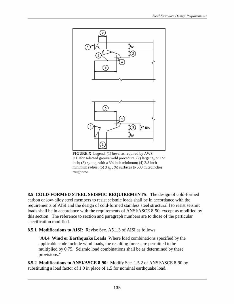
Steel Structure Design Requirements
135135
FIGURE X Legend: (1) bevel as required by AWSD1.1for selected groove weld procedure; (2) larger tbf or 1/2inch; (3) tbf to tbf with a 3/4 inch minimum; (4) 3/8 inchminimum radius; (5) 3 tbf , (6) surfaces to 500 microinchesroughness.
8.5 COLD-FORMED STEEL SEISMIC REQUIREMENTS: The design of cold-formedcarbon or low-alloy steel members to resist seismic loads shall be in accordance with therequirements of AISI and the design of cold-formed stainless steel structural l to resist seismicloads shall be in accordance with the requirements of ANSI/ASCE 8-90, except as modified bythis section. The reference to section and paragraph numbers are to those of the particularspecification modified.
8.5.1 Modifications to AISI: Revise Sec. A5.1.3 of AISI as follows:
"A4.4 Wind or Earthquake Loads Where load combinations specified by theapplicable code include wind loads, the resulting forces are permitted to bemultiplied by 0.75. Seismic load combinations shall be as determined by theseprovisions."
8.5.2 Modifications to ANSI/ASCE 8-90: Modify Sec. 1.5.2 of ANSI/ASCE 8-90 bysubstituting a load factor of 1.0 in place of 1.5 for nominal earthquake load.
2000 Provisions, Chapter 8
136136
8.6 LIGHT-FRAMED WALLS: When required by the requirements in Sec. 8.3 or 8.4, cold-formed steel stud walls designed in accordance with AISI and ANSI/ASCE 8-90 shall alsocomply with the requirements of this section.
8.6.1 Boundary Members: All boundary members, chords, and collectors shall be designed totransmit the specified induced axial forces.
8.6.2 Connections: Connections for diagonal bracing members, top chord splices, boundarymembers, and collectors shall have a design strength equal to or greater than the nominal tensilestrength of the members being connected or S0 times the design seismic force. The pull-outresistance of screws shall not be used to resist seismic forces.
8.6.3 Braced Bay Members: In stud systems where the lateral forces are resisted by bracedframes, the vertical and diagonal members in braced bays shall be anchored such that the bottomtracks are not required to resist uplift forces by bending of the track or track web. Both flangesof studs shall be braced to prevent lateral torsional buckling. In vertical diaphragm systems, thevertical boundary members shall be anchored so the bottom track is not required to resist upliftforces by bending of the track web.
8.6.4 Diagonal Braces: Provision shall be made for pretensioning or other methods ofinstallation of tension-only bracing to guard against loose diagonal straps.
8.6.5 Shear Walls: Nominal shear values for wall sheathing materials are given in Table 8.6.5. Design shear values shall be determined by multiplying the nominal values therein by a N factorof 0.55. In structures over one story in height, the assemblies in Table 8.6.5 shall not be used toresist horizontal loads contributed by forces imposed by masonry or concrete construction.
Panel thicknesses shown in Table 8.6.5 shall be considered to be minimums. No panels less than24 inches wide shall be used. Plywood or oriented strand board (OSB) structural panels shall beof a type that is manufactured using exterior glue. Framing members, blocking, or strappingshall be provided at the edges of all sheets. Fasteners along the edges in shear panels shall beplaced not less than 3/8 in. (9.5 mm) in from panel edges. Screws shall be of sufficient length toensure penetration into the steel stud by at least two full diameter threads.
The height to length ratio of wall systems listed in Table 8.6.5 shall not exceed 2:1.
Perimeter members at openings shall be provided and shall be detailed to distribute the shearingstresses. Wood sheathing shall not be used to splice these members.
Wall studs and track shall have a minimum uncoated base thickness of not less than 0.033 in.(0.84 mm) and shall not have an uncoated base metal thickness greater than 0.048 in. (1.22 mm). Panel end studs and their uplift anchorage shall have the design strength to resist the forcesdetermined by the seismic loads determined by Eq. 2.2.6-3 and Eq. 2.2.6-4.
TABLE 8.6.5 Nominal Shear Values for Seismic Forces for Shear WallsFramed with Cold-Formed Steel Studs (in pounds per foot)a, b
AssemblyDescription
Fastener Spacing at PanelEdges c (inches)
FramingSpacing
(inches o.c.)
Steel Structure Design Requirements
137137
6 4 3 2
15/32 rated Structural I sheathing(4-ply) plywood one side d
780 990 1465 1625 24
7/16 in. oriented strand board oneside d
700 915 1275 1700 24
NOTE: For fastener and framing spacing, multiply inches by 25.4 to obtain metric mm. a Nominal shear values shall be multiplied by the appropriate strength reduction factor N todetermine design strength as set forth in Sec. 8.6.5. b Studs shall be a minimum 1-5/8 in. by 3-1/2 in. with a 3/8-in. return lip. Track shall be aminimum 1-1/4 in. by 3-1/2 in. Both studs and track shall have a minimum uncoated base metalthickness of 0.033 in. and shall be ASTM A446 Grade A (or ASTM A653 SQ Grade 33 [newdesignation]). Framing screws shall be No. 8 x 5/8 in. wafer head self-drilling. Plywood and OSBscrews shall be a minimum No. 8 x 1 in. bugle head. Where horizontal straps are used to provideblocking, they shall be a minimum 1-1/2 in. wide and of the same material and thickness as the studand track. c Screws in the field of the panel shall be installed 12 in. o.c. unless otherwise shown. d Both flanges of the studs shall be braced in accordance with Sec. 8.6.3.
8.7 SEISMIC REQUIREMENTS FOR STEEL DECK DIAPHRAGMS: Steel deckdiaphragms shall be made from materials conforming to the requirements of AISI andANSI/ASCE 8-90. Nominal strengths shall be determined in accordance with approvedanalytical procedures or with test procedures prepared by a registered design professionalexperienced in testing of cold-formed steel assemblies and approved by the authority havingjurisdiction. Design strengths shall be determined by multiplying the nominal strength by aresistance factor, N, equal to 0.60 for mechanically connected diaphragms and equal to 0.50 forwelded diaphragms. The steel deck installation for the structure, including fasteners, shallcomply with the test assembly arrangement. Quality standards established for the nominalstrength test shall be the minimum standards required for the steel deck installation, includingfasteners.
8.8 STEEL CABLES: The design strength of steel cables shall be determined by therequirements of ASCE 19 except as modified by the Provisions. Sec. 5d of ASCE 19 shall bemodified by substituting 1.5(T4) where T4 is the net tension in cable due to dead load, prestress,live load, and seismic load. A load factor of 1.1 shall be applied to the prestress force to beadded to the load combination of Sec. 3.1.2 of ASCE 19.

139
Chapter 9
CONCRETE STRUCTURE DESIGN REQUIREMENTS
9.1 REFERENCE DOCUMENTS: The quality and testing of concrete and steel materials andthe design and construction of concrete components that resist seismic forces shall conform to therequirements of the reference listed in this section except as modified by the requirements of thischapter.
ACI 318 American Concrete Institute (ACI), Building Code Requirements for Struc-tural Concrete, excluding Appendix A, ACI 318, 1999.
ACI ITG/T1.1 American Concrete Institute (ACI), Acceptance Criteria for MomentFrames Based on Structural Testing (An ACI Provisional Standard), 1999.
ASME B1.1 American Society of Mechanical Engineers (ASME), Unified Inch ScrewThreads UN and UNR Thread Form, ASME B1.13, 1989.
ASME B18.2.1 American Society of Mechanical Engineers (ASME), Square and Hex Boltsand Screws, Inch Series, ASME B18.2.1, 1996
ASME B18.2.6.9 American Society of Mechanical Engineers (ASME),
ATC-24 Applied Technology Council (ATC), Guidelines for Seismic Testing ofComponents of Steel Structures, ATC-24, 1992
9.1.1 Modifications to ACI 318:
9.1.1.1: Insert the following notations in Sec. 21.0:
Ab = the area of the shank of the bolt or stud (in.2 or mm2)
bd = diaphragm width (ft)
cu! = neutral axis depth at Pu
! and Mn!.
Rp = height of the plastic hinge above critical section; shall be established on thebasis of substantiated test data or may be alternatively taken at 0.5Rw.
Pu! = 1.2D + 0.5L + E.
h = overall dimension of member in the direction of action considered.
hs = story height (ft)
Leff = length of diaphragm between inflection points (ft)
Sc Connection = nominal strength of connection cross section in flexural, shear, or axial loadper Sec. 21.2.7.3.

2000 Provisions Chapter 9
140
Se Connection = moment, shear, or axial force at strong connection cross section correspond-ing to probable strength at the nonlinear action location, taking gravity loadeffects into consideration per Sec. 21.2.8.3.
Sn Connection = nominal strength of connection cross section in flexural, shear, or axial loadper Sec. 21.2.7.3.
Spr = probable strength of connection cross section in flexural, shear, or axialload. See Sec. 21.11.5.
Sy = yield strength of connection cross section in flexural, shear, or axial loadaction as determined from physical experiments on the connection or the useof analytical models for the response of the connection that are based on theresults of physical experiments on connections with characteristics similarto those being modeled. See Sec. 21.11.5.
)E = elastic design displacement at the top of the wall using gross section proper-ties and code-specified seismic forces.
)i = inelastic deflection at top of wall = )t - )y.
)m = Cd)s.
)s = design level response displacement, which is the total drift or total storydrift that occurs when the structure is subjected to the design seismic forces.
)t = total deflection at the top of the wall equal to Cd times the elastic designdisplacement using cracked section properties or may be taken as(Ig/Ieff)Cd)E. Ig is the gross moment of inertia of the wall and Ieff is theeffective moment of inertia in the wall. Ieff may be taken as 0.5Ig.
)y = displacement at the top of the wall corresponding to yielding of the tensionreinforcement at critical section or may be taken as (Mn
!/ME))E where ME
equals moment at critical section when top of wall is displaced )E. Mn! is
nominal flexural strength of critical section at Pu!.
Ny = yield curvature which may be estimated as 0.003/Rw.
R = dynamic amplification factor from Sec. 21.2.8.3 and 21.2.8.4.
9.1.1.2: Insert the following definitions in Sec. 21.1:
Anchorage – The means by which, for precast construction, the force in the connection istransferred into the precast or cast-in-place member.
Connection – An element that joins two precast members or a precast member and a cast-in-place member.
Connection Region – The portion of the precast or cast-in-place member through which theconcentrated forces from the connection and anchorage are transferred to the concrete. Its extentfrom the connection is the distance for the forces to be distributed over the cross section and shallbe permitted to not exceed the largest dimension of that cross section.
Concrete Structure Design Requirements
141
Design Displacement – Design story drift as specified in Sec. 5.2.2.4.3 of the 2000 NEHRPRecommended Provisions.
Design Load Combinations – Combinations of factored loads and forces specified in Sec. 5.2.7of the the 2000 NEHRP Recommended Provisions.
Dry Connection – Connection used between precast members which does not qualify as a wetconnection.
Joint – The geometric volume common to intersecting members.
Moment Frame
Special moment frame – A cast-in-place frame complying with the requirements of Sec.21.2 through 21.5 in addition to the requirements for ordinary moment frames or a precastconcrete frame complying with the requirements for a cast-in-place frame and Sec. 21.11.
Nonlinear Action Location – Center of the region of yielding in flexure, shear, or axialaction.
Nonlinear Action Region – The member length over which nonlinear action takes place. It shallbe taken as extending a distance of no less than h/2 on either side of the nonlinear actionlocation.
Strong Connection – A connection that remains elastic while the designated nonlinear actionregions undergo inelastic response under the design basis ground motion.
Structural Walls
Ordinary precast concrete structural wall – A wall incorporating precast concreteelements and complying with the requirements of Chapters 1 through 18 with the require-ments of Chapter 16 superseding those of Chapter 14. Where connections between wallpanels are required or anchorage of wall panels to foundations is required for resistance tooverturning, Type Y or Type Z connections shall be provided as required by Sec. 21.11.6.
Special precast concrete structural wall – A wall complying with the requirements of Sec.21.11 in addition to the requirements for ordinary reinforced concrete structural walls.
Wall Pier – A wall segment with a horizontal length-to-thickness ratio of at least 2.5, but notexceeding 6, whose clear height is at least two times its horizontal length.
Wet Connection – A connection that uses any of the splicing methods permitted by Sec. 21.3.2.3or 21.3.2.4 to connect precast members and uses cast-in-place concrete or grout to fill thesplicing closure.
Wet Connection – A connection in precast construction that uses any of the splicing methodspermitted by Sec. 21.2.6, 21.2.7, or 21.3.2.3 to connect precast members and uses cast-in-placeconcrete or grout to fill the splicing closure.
9.1.1.3: Revise Sec. 21.2.1.2, 21.2.1.3, and 21.2.1.4 as follows:
“21.2.1.2 For structures assigned to Seismic Design Categories A and B, provisions ofChapters 1 through 18 and 22 shall apply except as modified by the requirements of

2000 Provisions Chapter 9
142
Chapter 9 of the 2000 NEHRP Recommended Provisions. Where the seismic designloads are computed using provisions for intermediate or special concrete systems, therequirements of Chapter 21 for intermediate or special systems, as applicable, shall besatisfied.
“21.2.1.3 For structures assigned to Seismic Design Category C, intermediate or specialmoment frames or ordinary or special reinforced concrete structural walls shall be usedto resist seismic forces induced by earthquake motions. Where the design seismic loadsare computed using the provisions for special concrete systems, the requirements ofChapter 21 for special systems, as applicable, shall be satisfied.
“21.2.1.4 For structures assigned to Seismic Design Categories D, E and F, specialmoment frames, special reinforced concrete structural walls, diaphragms and trusses, andfoundations complying with Sec. 21.2 through 21.8 and 21.11 shall be used to resistforces induced by earthquake motions. Frame members not proportioned to resistearthquake forces shall comply with Sec. 21.9.”
9.1.1.4: Insert the following new Sec. 21.2.1.6 and 21.2.1.7:
21.2.1.6 Precast concrete seismic-force-resisting systems used in regions of high seismicrisk or for structures assigned to high seismic performance or design categories shallsatisfy the requirements of Sec. 21.11 in addition to the requirements of Sec. 21.2through 21.9.
“21.2.1.7 In structures having precast gravity load-carrying systems, the seismic-force-resisting system shall be one of the systems listed in Table 5.2.2 of the 2000 NEHRPRecommended Provisions and shall be well distributed using one of the followingmethods:
“1. The diaphragm or diaphragm segment between seismic-force-resisting systems shallbe designed to resist a force not less than S0 times the force determined in accor-dance with Sec. 5.2.5.4 of the 2000 NEHRP Recommended Provisions. The chordforce determined in accordance with Sec. 21.7.8.1 of ACI 318 shall be increased bya factor equal to:
d
eff
d
sb
L
b
h
1 0 4
12
2
+
.
but not less than unity where:
Leff = length of diaphragm between inflection points, ft,
hs = story height, ft, and
bd = diaphragm width, ft
Concrete Structure Design Requirements
143
“Where the seismic-force-resisting system consists of moment resisting frames, atleast (Nb/4) + 1 of the bays (rounded up to the nearest integer) along any frame lineat any story shall be part of the seismic-force-resisting system where Nb is the totalnumber of bays along that line at that story. This requirement applies to only thelower two thirds of the stories of buildings three stories or taller.
“2. All beam-to-column connections that are not part of the seismic-force-resistingsystem shall be designed in accordance with the following:
“Connection Design Force. The connection shall be designed to developstrength M. M is the moment developed at the connection when the frame isdisplaced by )s assuming fixity at the connection and a beam flexural stiffnessof no less than one half of the gross section of stiffness. M shall be sustainedthrough a deformation of )m.
“Connection Characteristics. The connection shall be permitted to resist moment inone direction only, positive or negative. The connection at the opposite end of themember shall resist moment with the same positive or negative sign. The connectionshall be permitted to have zero flexural stiffness up to a frame displacement of )m.
“In addition, complete calculations for the deformation compatibility of the gravity loadcarrying system shall be made in accordance with Sec. 5.2.2.4.3 of the 2000 NEHRPRecommended Provisions using cracked section stiffness in the seismic-force-resistingsystem and the diaphragm.
“Where gravity columns are not provided with lateral support on all sides, a positiveconnection shall be provided along each unsupported direction parallel to a principalplan axis of the structure. The connection shall be designed for a horizontal force equalto 4 percent of the axial load strength, Po, of the column.
“The bearing length shall be calculated to include end rotation, sliding, and othermovements of precast ends at supports due to earthquake motions in addition to othermovements and shall be at least 2 inches more than that required for bearing strength.”
9.1.1.5: Change Sec. 21.2.5.1 as follows and insert the following new Sec. 21.2.5.2 and 21.2.5.3.
“21.2.5.1 Except as permitted in 21.2.5.2 and 21.2.5.3, reinforcement resisting earthquake-induced flexural and axial forces in the frame members and in wall boundary elements shallcomply with a ASTM A 706. ASTM A 615 Grades 40 and 60 reinforcement shall bepermitted if (a) the actual yield strength based on mill tests does not exceed the specifiedyield strength by more than 18,000 psi (retests shall not exceed this value by more than anadditional 3000 psi) and (b) the ratio of the actual ultimate tensile strength to the actualtensile yield strength is not less than 1.25.
“21.2.5.2 Prestressing tendons shall be permitted in the flexural members of framesprovided the average prestress, fpc, calculated for an area equal to the member’s shortestcross-sectional dimension multiplied by the perpendicular dimension shall not exceed the
lesser of 700 psi or at locations of nonlinear action where prestressing tendons aref c
′6
used in members of frames.
2000 Provisions Chapter 9
144
“21.2.5.3 Unless the seismic-force-resisting frame is qualified for use through structuraltesting as required by 21.8.3.1, for members in which prestressing tendons are used togetherwith mild steel reinforcement to resist earthquake-induced forces, prestressing tendons shallnot provide more than one quarter of the strength for either positive or negative moment atthe nonlinear action and be anchored at the exterior face of the joint or beyond.
“21.2.5.4 Anchorages for tendons shall be demonstrated to perform satisfactorily for seismicloadings. Anchorage assemblies shall withstand, without failure, a minimum of 50 cycles ofloading between 40 and 85 percent of the minimum tensile strength of the prestressing steel.
9.1.1.6: Add the following new Sec. 21.4.5.3:
“21.4.5.3 At any section where the design strength, NPn, of the column is less than the sumof the shear Ve computed in accordance with 21.4.5.1 for all the beams framing into thecolumn above the level under consideration, special transverse reinforcement shall beprovided. For beams framing into opposite sides of the column, the moment componentsmay be assumed to be of opposite sign. For determination of the nominal strength, Pn, of thecolumn, these moments may be assumed to result from the deformation of the frame in anyone principal axis.”
9.1.1.7: In Sec. 21.6.3, change “factored load combinations” to “design load combinations.”
9.1.1.8: Modify Sec. 21.6 by adding a new Sec. 21.6.10 to read as follows:
“21.6.10 Wall Piers and Wall Segments
“21.6.10.1 Wall piers not designed as part of a special moment frame shall have transversereinforcement designed to satisfy the requirements of Sec. 21.6.10.2
“Exceptions:
“1. Wall piers that satisfy Sec. 21.9.
“2. Wall piers along a wall line within a story where other shear wall segments providelateral support to the wall piers and such segments have a total stiffness of at leastsix times the sum of the stiffness of all the wall piers.
“21.6.10.2 Transverse reinforcement shall be designed to resist the shear forces determinedfrom Sec. 21.4.5.1 and 21.3.4.2. Where the axial compressive force, including earthquakeeffects , is less than As fc! /20, transverse reinforcement in wall piers is permitted to havestandard hooks at each free end and in lieu of hoops. Spacing of transverse reinforcementshall not exceed 6 inches (152 mm). Transverse reinforcement shall be extended beyond thepier clear height for at least the development length of the largest longitudinal reinforcementin the wall pier.”
9.1.1.9: Change Sec. 21.8.1.1 to read as follows:
“21.8.1.1 Foundations resisting earthquake-induced forces or transferring earthquake-induced forces between structure and ground shall comply with requirements of Sec. 21.8and other applicable code provisions unless modified by Chapter 7 of the 2000 NEHRPRecommended Provisions.
Concrete Structure Design Requirements
145
9.1.1.10: Revise Sec. 21.9.3.3 to read as follows:
“21.9.23.3 Members with factored gravity axial force exceeding Ag fc!/10 shall satisfy Sec.21.4.3.1, 21.4.4, 21.4.5, and 21.5.2.1. The maximum longitudinal spacing of ties shall be so
for the full column height. The spacing, so, shall not be more than six diameters of thesmallest longitudinal bar enclosed or 6 in. (152 mm), whichever is smaller. Lap splices oflongitudinal reinforcement in such members need not satisfy Sec. 21.4.3.2 in structureswhere the seismic-force-resisting system does not include special moment frames.”
9.1.1.11: Insert in Sec. 21.10 the following new Sec. 21.10.7:
“21.10.7 Precast concrete moment frames. For structure assigned to Seismic DesignCategory C, precast concrete seismic-force-resisting frames shall be permitted provided theframe conforms to 21.10.1 through 21.10.5 and Type Y or Type Z connections as defined in21.11.5 are used.”
9.1.1.12: Insert new Sec. 21.11 as follows:
“21.11 Precast concrete special moment frames and special structural walls.
“21.11.1 Scope.
Requirements of 21.11 apply to special moment frames, and to special reinforced concretestructural walls, resisting the earthquake induced forces and utilizing precast concreteelements.”
“21.11.2 Seismic-force-resisting system requirements.
“21.11.2.1 A precast seismic-force-resisting system shall be permitted providing it satisfieseither of the following criteria:
“1. The behavior of the system for forces up to and including those at the designdisplacement emulates the behavior of monolithic reinforced concrete construction andthe system satisfies 21.11.3 or
“2. The system relies on its unique properties as a structure composed of interconnectedprecast elements and is demonstrated by experimental evidence and analysis to satisfySec. 21.2 through 21.7 of Chapter 21. Substantiating experimental evidence of accept-able performance of those elements required to sustain inelastic deformations shall bebased upon cyclic testing of specimens representing those elements and shall satisfy21.11.4.1 for special precast concrete moment frames and 21.11.4.2 for special precastconcrete structural walls.
“21.11.3 Emulation Design. Precast structural systems emulating the behavior of mono-lithic reinforced concrete construction shall satisfy 21.11.3.1 where ductile connections areused and 21.11.3.2 where strong connections are used.
“21.11.3.1 Precast structural systems utilizing either wet or dry ductile connections atnonlinear action locations shall comply with all the applicable requirements of monolithicconcrete construction for resisting seismic forces and satisfy the following:

2000 Provisions Chapter 9
146
“1. Where the moment acting on the connection is assumed equal to Mpr, the co-existingshear on the connection shall be no greater than 0.5Sn Connection and
“2. The nominal shear strength for the connection shall not be less than the shear strengthsof the members immediately adjacent to that connection.
“21.11.3.2 Precast structural systems not meeting the requirements of 21.11.2 shall utilizestrong connections resulting in nonlinear response away from connections. Design shallsatisfy the requirements of 21.11.5 in addition to the applicable requirements of monolithic concrete construction for resisting seismic forces except that the provisions of 21.3.1.2 shallapply to segments between nonlinear action locations.
“21.11.4 Interconnected element design.
“21.11.4.1 For special moment frames composed of interconnected precast elements,substantiating experimental evidence and analysis shall satisfy the requirements of ACI ITG/T1.1. It shall also be demonstrated by experimental evidence that the modules used forthe validation testing of ACI ITG/T1.1 have the ability to carry, at 5 percent or greater driftratios, the gravity loads that act on them in the generic frame.
“21.11.4.2 For special structural wall systems composed of precast elements substantiatingexperimental evidence and analysis shall meet the requirements of Sec. 4.1, 4.2, 5.2, 5.3, 6.0,7.0 and 8.0 of ACI ITG/T1.1 and:
2. The minimum stack module shall be a stack of wall panels at least two panels high.
2. For the third cycle at drift ratios equal to or exceeding the limiting drift ratio, the criteriafor acceptance shall be that:
a. Lateral load resisting capacity of the module shall be at least 80 percent of the peaklateral load;
b. The relative energy dissipation ratio, as defined in ACI ITG/T1.1-99, shall equal orexceed 15 percent for that third cycle; and
c. The stiffness at zero drift shall equal or exceed that required by ACI ITG/T1.1-99.
“3. The limiting drift ratio in percent shall satisfy the following criterion:
[ ]10 0 67 0 5 30. . . .≤ + ≤h lw w
“21.11.4.3 Unless there is substantial experimental evidence obtained during a priordevelopment program, the validation tests required in Sec. 21.11.4.1 and 21.11.4.2 shall:
1. Be conducted at full scale and
2. Be at least two in number for each characteristic configuration of intersecting beams andcolumns or structural walls.
“21.11.4.4 The nonlinear response history analysis of Sec. 5.7 of the 2000 NEHRP Recom-mended Provisions shall be used to design the special precast concrete moment frame and
Concrete Structure Design Requirements
147
structural wall systems using the force-deformation characteristics from the subassemblagetests required by Sec. 21.11.4.1 or Sec. 21.11.4.2.
“21.11.5 Emulation design of frames using strong connections.
“21.11.5.1 Location. Nonlinear action location shall be selected so that there is a strongcolumn/weak beam deformation mechanism under seismic effects. The nonlinear actionlocation shall be no closer to the near face of strong connection than h/2. For column-to-footing connections where nonlinear action may occur at the column base to complete themechanism, the nonlinear action location shall be no closer to the near face of the connectionthan h/2.
“21.11.5.2 Anchorage and splices. Reinforcement in nonlinear action region shall be fullydeveloped outside both the strong connection region and the nonlinear action region. Noncontinuous anchorage reinforcement of strong connection shall be fully developedbetween the connection and the beginning of nonlinear action region. Lap splices areprohibited within connections adjacent to a joint.
“21.11.5.3 Design forces. Design strength of strong connections shall be based on :
φ ψS SnConnection eConnection≥
“ The dynamic amplification factor, R, shall be taken as 1.0.
“21.11.5.4 Column-to-column connection. The strength of such connection shall complywith 21.2.7.3 with the R taken as 1.4. Where the column-to-column connections occur, thecolumns shall be provided with transverse reinforcement as specified in 21.4.4.1 through21.4.4.3 over their full height in the factorial axial compressive force in these members,including seismic effects, exceeds Agfc
!/10.
“Exception: Where column-to-column connection is located within the middle third ofthe column clear height, the following shall apply: (a) the design moment strength, NMn, the connection shall not be less than 0.4 times the maximum Mpr for the column withinthe story height and (b) the design shear strength, NVn, of the connection shall not be lessthan that determined per 21.4.5.1.
“21.11.5.5 Column-face connection. Any strong connection located outside the middlehalf of a beam span shall be a wet connection unless a dry connection can be substantiated byapproved cyclic test results. Any mechanical connector located within such a column-facestrong connection shall develop in tension or compression, as required, at least 40 percent ofthe specified yield strength, fy, of the bar.
“21.11.6 Connections.
“21.11.6.1 At dry connections that are nonlinear action locations, displacements both in thedirection of the action of the connection and the transverse to it shall be controlled.
“21.11.6.2 Dry connections shall be mechanical splices that are Type 2 at nonlinear actionlocations. Type 1 mechanical splices and welded splices shall be permitted elsewhere.
2000 Provisions Chapter 9
148
“21.11.6.3 Based on the results of physical experiments and analytical modeling of connec-tions, their anchorage and their connection regions, both dry and wet connections at nonlin-ear action locations shall be classified as either Type Y or Type Z connections, as follows:
1. Type Y connections shall conform to 21.11.6.4 and develop, for the specified loading,ductility ratios greater than 4.0.
2. Type Z connections shall conform to 21.11.6.5 and develop, for the specified loadingductility ratios greater than 8.0.
“Testing of connections and evaluation of results shall be made in accordance with theprinciples specified in ACI ITG/T1.1 and ATC-24.
“21.11.6.4 Type Y connections shall develop under flexural, shear, and axial load actions, asrequired, a probable strength, Spr, determined using a N value of unity, that is not less than125 percent or more of the yield strength, Sy, of the connection. The anchorage on either side of the connection shall be designed to develop 1.3Spr in tension and shall be connecteddirectly by mechanical splice, welded splice, or tension lap splice to the principalreinforcement of the precast or cast-in-place element.
“21.11.6.5 Type Z connections shall develop under flexural, shear and axial load actions, asrequired, a probable strength, Spr, determined using a N value of unity, that is not less than140 percent of the yield strength, Sy of the connection. The anchorage on either side of theconnection shall be designed to satisfy the requirements for Type Y connections in tensionand in compression, and the connection region shall be able to develop 1.3Spr. Equilibrium-based plasticity models (strut-and-tie models) shall be permitted to be used for design of theconnection region. Confinement reinforcement in the form of closed hoops or spirals with ayield force equal to not less than 5 percent of the compressive force and having a spacing notgreater than 3 in. shall be provided where the local compressive stress exceeds 0.7fc
!.
“Exception: Connections in nonlinear action regions in test modules used to qualifyseismic-force resisting systems for use based on structural testing in accordance with21.11.3 shall be deemed to satisfy the requirements of this provision.
“21.11.6.6 Connections at nonlinear action locations shall be Type Z connections. Type Yconnections shall be permitted at cross sections other than nonlinear action locations.
“21.11.6.7 Connections and the structural components of which they are part shall have aquality assurance plan satisfying the requirements of the 2000 NEHRP RecommendedProvisions Sec. 3.2.1 and 3.2.2.”
9.2 ANCHORING TO CONCRETE:
9.2.1 Scope:
9.2.1.1: These provisions provide design requirements for structural anchors in concrete used totransmit structural loads from attachments into concrete members or from one connected memberto another by means of tension, shear, or a combination of tension and shear. Safety levelsspecified are intended for in-service conditions rather than for short-term handling andconstruction conditions.
Concrete Structure Design Requirements
149
9.2.1.2: These provisions apply to both cast-in concrete anchors such as headed studs, headedbolts or hooked bolts, and post-installed anchors, such as expansion anchors and undercutanchors. Specialty inserts, through bolts, bolts anchored to embedded large steel plates, adhesiveor grouted bounded anchors, and direct anchors, such as powder or pneumatic actuated nails orbolts are not included. Reinforcement used as a part of the embedment shall be designed inaccordance with ACI 318.
9.2.1.3: Headed studs and headed bolts that have a geometry consistent with ASME B1.1,B18.2.1, and B18.2.6.9 shall be designed by Sec. 9.2.4. Hooked bolts that have a geometry thathas been demonstrated to result in pullout strength without the benefit of friction in uncrackedconcrete equal to or exceeding 1.4 Np (where Np is given by Eq. 9.2.5.3.5) are included.
9.2.1.4: Post-installed anchors shall be tested before use to determine their nominal strength inuncracked concrete, cracked concrete, or both and also to verify their compliance with therequirements of these design provisions for reliability and performance under anticipatedconditions of service. Such tests shall be conducted by an independent testing agency and shallbe verified by a registered design professional with full description and details of the testingprogram, procedures, results, and conclusions. The test program shall be comprehensive andshall include tests, results, and analysis for the requirements of Sec. 9.2.1.4.1 and 9.2.1.4.3.
9.2.1.4.1 Reference Tests: Reference tests shall establish failure modes, technical data, and kfactors to use with these design provisions for uncracked or cracked concrete or both.
9.2.1.4.2 Reliability Tests: Reliability tests shall establish the appropriate category for thefastener using tests of sensitivity to reduced installation effort, sensitivity to low strengthconcrete with larger tolerance drill bit in cracked or uncracked concrete, and sensitivity to highstrength concrete with a lower tolerance drill bit in cracked or uncracked concrete. Tests shallalso be performed in uncracked concrete with repeated loading and in cracked concrete with anopening and closing crack of at least 1,000 cycles to establish the fastener suitability.
9.2.1.4.3 Service-condition Tests: Service-condition tests shall establish requirements for edgedistance, spacing between fasteners, splitting near an edge, shear capacity and pryout. Forcracked concrete, simulated seismic qualification tests shall establish the ability of the fastener toperform in tension and shear under seismic conditions.
9.2.1.5: Load applications that are predominantly high cycle fatigue or impact are not covered bythese provisions.
9.2.2 Notations and Definitions:
9.2.2.1 Notations:
Ab = bearing area of the head of the stud or anchor bolt (in2).
ANo = projected concrete failure area of one anchor, for calculation of strength in tension, whennot limited by edge distance or spacing, as defined in Sec. 9.2.5.2.1 (in2). (see FigureC9.2.5.2.2-1).

2000 Provisions Chapter 9
150
AN = projected concrete failure area of an anchor or group of anchors for calculation ofstrength in tension as defined in Sec. 9.2.5.2.1, in2. AN shall not be taken greater thannANo (see Figure C9.2.5.2.1-2).
Ase = effective cross-sectional area of anchor (in2).
Asl = effective cross-sectional area of expansion or undercut anchor sleeve, if sleeve is withinshear plane (in2).
AVo = projected concrete failure area of one anchor, for calculation of strength in shear, whennot limited by corner influences, spacing, or member thickness, as defined in Sec.9.2.6.2.1 ( in2) (See Figure C9.2.6.2.1-1).
AV = projected concrete failure area of an anchor or group of anchors, for calculation ofstrength in shear, as defined in Sec. 9.2.6.2.1 ( in2). AV shall not be taken greater thannAVo. (see Figure C9.2.6.2.1-2).
c = distance from center of an anchor shaft to the edge of concrete (in.).
c1 = distance from the center of an anchor shaft to the edge of the concrete in one direction(in). Where shear force is applied to an anchor, c1 is in the direction of the shear force(see Figure C9.2.6.2.1-2).
c2 = distance from center of an anchor shaft to the edge of the concrete in the directionorthogonal to c1 ( in.).
cmax = the largest of the edge distances that are less than or equal to 1.5 hef (in.) used only forthe case of 3 or 4 edges.
cmin = the smallest of the edge distances that are less than or equal to 1.5 hef (in.)
do = outside diameter of anchor or shaft diameter of headed stud, headed anchor bolt, orhooked anchor (in.) (see also Sec. 9.2.8.4).
du = diameter of head of stud or anchor bolt or equivalent diameter of effective perimeter ofan added plate or washer at the head of the anchor (in.).
eh = distance from the inner surface of the shaft of a J-bolt to the outer tip of the J- or L-bolt(in.).
eN! = eccentricity of normal force on a group of anchors; the distance between the resultant
tension load on a group of anchors in tension and the centroid of the group of anchorsloaded in tension (in.) (see Figures C9.2.5.2.4-1 and -2).
ev! = eccentricity of shear force on a group of anchors; the distance between the point of shear
force application and the centroid of the group of anchors resisting shear in the directionof the applied shear (in.).
fc! = specified compressive strength of concrete (psi).
fct = specified tensile strength of concrete (psi).
fr = modules of rapture of concrete (psi).
Concrete Structure Design Requirements
151
ft = calculated tensile stress in a region of a member (psi).
fy = specified yield strength of anchor steel (psi).
fut = specified tensile strength of anchor steel (psi).
futsl = specified tensile strength of anchor sleeve (psi).
h = thickness of member in which an anchor is anchored measured parallel to the anchor axis(in.).
hef = effective anchor embedment depth (in.) (see Sec. 9.2.8.5 and Figure C9.2.2.2).
k = coefficient for basic concrete breakout strength in tension.
kcp = coefficient for pryout strength.
l = load bearing length of anchor for shear, not to exceed 8do (in.).
l = hef for anchors with a constant stiffness over the full length of the embedded section,such as headed studs or post-installed anchors with one tubular shell over the full lengthof the embedment depth.
l = 2do for torque-controlled expansion anchors with a distance sleeve separated from theexpansion sleeve.
n = number of anchors in a group.
Nb = basic concrete breakout strength in tension of a single anchor in cracked concrete, asdefined in Sec. 9.2.5.2.2 (lb).
Ncb = nominal concrete breakout strength in tension of a single anchor, as defined in Sec.9.2.5.2.1 (lb).
Ncbg = nominal concrete breakout strength in tension of a group of anchors, as defined in Sec.
9.2.5.2.1 (lb).
Nn = nominal strength in tension (lb).
Np = pullout strength in tension of a single anchor in cracked concrete, as defined in Sec.9.2.5.3.4 or 9.2.5.3.5 (lb).
Npn = nominal pullout strength in tension of a single anchor, as defined in Sec. 9.2.5.3.1 (lb).
Nsb = side-face blowout strength of a single anchor (lb).
Nsbg = side-face blowout strength of a group of anchors (lb).
Ns = nominal strength of a single anchor in tension as governed by the steel strength, asdefined in Sec. 9.2.5.1.2 (lb).
Nu = factored tensile load (lb).
s = anchor center-to center spacing (in).
so = spacing of the outer anchors along the edge in a group (in).

2000 Provisions Chapter 9
152
t = thickness of washer or plate (in).
Vb = basic concrete breakout strength in shear of a single anchor in cracked concrete, asdefined in Sec. 9.2.6.2.2 or 9.2.6.2.3 (lb).
Vcb = nominal concrete breakout strength in shear of a single anchor as defined in Sec.9.2.6.2.1 (lb).
Vcbg = nominal concrete breakout strength in a shear group of anchors as defined in Sec.9.2.6.2.1 (lb).
Vcp = nominal concrete pryout strength, as defined in Sec. 9.2.6.3 (lb).
Vn = nominal shear strength (lb).
Vs = nominal strength in shear of a single anchor as governed by the steel strength as definedin Sec. 9.2.6.1.1 (lb).
Vu = factored shear load (lb).
N = strength reduction factor (see Sec. 9.2.4.4 and 9.2.4.5).
Q1 = modification factor, for strength in tension, to account for anchor groups loadedeccentrically as defined in Sec. 9.2.5.2.4.
Q2 = modification factor, for strength in tension, to account for edge distances smaller than1.5hef as defined in Sec. 9.2.5.2.5
Q3 = modification factor, for strength in tension, to account for cracking as defined in Sec.9.2.5.2.6 and 9.2.5.2.7.
Q4 = modification factor, for pullout strength, to account for cracking as defined in Sec. 9.2.5.3.1 and Sec. 9.2.5.3.6.
Q5 = modification factor, for strength in shear, to account for the anchor groups loadedeccentrically as defined in Sec. 9.2.6.2.5.
Q6 = modification factor, for strength in shear, to account for edge distances smaller than 1.5c1
as defined in Sec. 9.2.6.2.6.
Q- = modification factor, for strength in shear, to account for cracking, as defined in Sec.9.2.6.2.7
9.2.2.2 Definitions:
Anchor: A metallic element either cast into concrete or post-installed into a hardened concretemember and used to transmit applied loads including straight bolts, hooked bolts (J-or L-bolt),headed studs, expansion anchors, undercut anchors, or inserts.
Anchor Group: A number of anchors of approximately equal effective embedment depth witheach anchor spaced as less than three times its embedment depth from one or more adjacentanchors.
Concrete Structure Design Requirements
153
Anchor Pullout Strength: The strength corresponding to the anchoring device or a majorcomponent of the device sliding out from concrete without breaking out a substantial portion ofthe surrounding concrete.
Attachment: The structural assemble, external to the surface of the concrete, that transmitsloads to the anchor.
Brittle Steel Element: An element with a tensile test elongation of less than 14 percent over a 2in. gage length reduction in area of less than 40 percent, or both.
Concrete Breakout Strength: The strength corresponding to a volume of concrete surroundingthe anchor or group of anchors separating from the memeber.
Concrete Pryout Strength: The strength corresponding to formation of a concrete spall behinda short, stiff anchor with an embedded base that is displaced in the direction opposite to theapplied shear force.
Distance Sleeve: A sleeve that encases the center part of an undercut anchor, a torque-controlledexpansion anchor, or a displacement-controlled expansion anchor but does not expand.
Ductile Steel Element: An element with a tensile test elongation of at least 14 percent over a 2in. gage length and reduction in area of at least 40 percent.
Edge Distance: The distance from the edge of the concrete surface to the center of the nearestanchor.
Effective Embedment Depth: The overall depth through which the anchor transfers force to thesurrounding concrete. The effective embedment depth normally will be the depth of the failuresurface in tension applications. For cast-in headed anchor bolts and headed studs, the effectiveembedment depth is measured from the bearing contact surface of the head. (See FigureC9.2.2.1.)
Expansion Anchor: A post-installed anchor inserted into hardened concrete that transfers loadsinto the concrete by direct bearing and/or friction. Expansion anchors may be torque-controlled,where the expansion is achieved by a torque acting on the screw or bolt, or displacement-controlled, where the expansion is achieved by impact forces acting on a sleeve or a plug and theanchorage is controlled by the length of travel of the sleeve or plug.
Expansion Sleeve: The outer part of an expansion anchor that is forced outward by the centerpart, either by applied torque or impact, to bear against the sides of the pre-drilled hole.
5 Percent Fractile: A statistical term meaning 90 percent confidence that 95 percent of theactual strengths will exceed the nominal strength. Determination shall include the number oftests when evaluating data.
Hooked Bolt: A cast-in anchor anchored mainly by mechanical interlock from the 90-degreebend (L-bolt) or 180-degree bend (J-bolt) at its lower end.
Insert (specialty insert): Predesigned and pre-fabricated cast-in anchors specifically designedfor attachment of bolted or slotted connections. Inserts often are used for handling,transportation, and erection but are used also for anchoring structural elements.
2000 Provisions Chapter 9
154
Post-Installed Anchor: An anchor installed in hardened concrete. Expansion anchors andundercut anchors are examples of post-installed anchors.
Projected Area: The area on the free surface of the concrete member that is used to representthe larger base of the assumed rectilinear failure surface.
Side-Face Blowout Strength: The strength of the anchors with deeper embedment but thinnerside cover corresponding to concrete spalling on the side face around the embedded head whileno major breakout occurs at the top concrete surface.
Undercut Anchor: A post-installed anchor anchored mainly by mechanical interlock providedby an undercutting in the anchoring concrete. The undercutting is achieved with a special drillbefore installing the anchor or, alternatively, by the anchor itself during its installation.
9.2.3 General Requirements:
9.2.3.1: Anchors and anchor groups shall be designed for critical effects of factored loads asdetermined by elastic analysis. Plastic analysis approaches are permitted where nominal strengthis controlled by ductile steel elements provided that deformational compatibility is taken intoaccount.
9.2.3.2: Except for load combinations that include earthquake forces or effects, anchors shall bedesigned for all load combinations outlined in Sec. 9.2 of ACI 318. Where resistance tospecified earthquake loads or forces, E, are included in the design, the load combinations Sec.5.2.7 of this document shall apply.
9.2.3.3: When anchor design includes seismic loads, the following additional requirements shallapply.
9.2.3.3.1: In structures assigned to Seismic Design Categories C, D, E, or F post-installedstructural anchors for use under Sec. 9.2.3.2 shall have passed the simulated seismic tests inaccordance with Sec. 9.2.1.4.
9.2.3.3.2: In structures assigned to Seismic Design Categories C, D, E or F, the design strengthof anchors shall be taken as 0.75 N Vn, where N is given in Sec. 9.2.4.4 or 9.2.4.5 and Nn and Vn
are determined in accordance with Sec. 9.2.4.1.
9.2.3.3.3: In structures assigned to Seismic Design Categories C, D, E or F, anchors shall bedesigned to be governed by tensile or sheer strength of a ductile steel element unless Sec.9.2.3.3.4 is satisfied.
9.2.3.3.4: In lieu of Sec. 9.2.3.3.3, the attachment that the anchor is connecting to the structureshall be designed so that the member being attached will undergo ductile yielding at a load levelno greater than 75 percent of the minimum anchor design strength or the minimum anchor designstrength is at least S0 times the attachment force determined from design loads of the attachedstructure or 2.5 times the attachment force determined from the design loads of the attachednonstructural component.
9.2.3.4: All provisions for anchor axial tension and shear strength apply to normal-weightconcrete. When lightweight aggregate concrete is used, provisions for Nn and Vn shall be

Concrete Structure Design Requirements
155
modified by multiplying all values of affecting Nn and Vn by 0.75 for “all lightweight”′fc
concrete and 0.85 for “sand-lightweight” concrete. Linear interpolation shall be permitted whenpartial sand replacement is used.
9.2.3.5: The values of fc! used for calculations in these provisions shall not exceed 10,000 psi for
cast-in anchors and 8000 psi for post-installed anchors.
9.2.4 General Requirements for Strength of Structural Anchors:
9.2.4.1: Strength design of structural anchors shall be based on the computation or test evalua-tion of the following:
a. Steel strength of anchor in tension Sec. 9.2.5.1,
b. Steel strength of anchor is shear Sec. 9.2.6.1,
c. Concrete breakout strength of anchor in tension Sec. 9.2.4.2 and 9.2.5.2
d. Concrete breakout strength of anchor in shear Sec. 9.2.4.2 and 9.2.6.2,
e. Pullout strength of anchor in tension Sec. 9.2.4.2 and 9.2.5.3,
f. Concrete side-face blowout strength of anchor in tension Sec. 9.2.4.2 and 9.2.5.4,
g. Concrete pryout strength of anchor in shear Sec. 9.2.4.2 and 9.2.6.3,
h. Required edge distances, spacings and thickness to preclude splitting failure Sec. 9.2.4.2 and9.2.8.
9.2.4.1.1: For the design of anchors, except as required in Sec. 9.2.3.3:
(9.2.4.1.1-1)φN Nn u≥
(9.2.4.1.1-2) φV Vn u≥
9.2.4.1.2: When both Nu and Vu are present, interaction effects shall be considered in accordancewith 9.2.4.3.
9.2.4.1.3: In Eq. 9.2.4.1.1-1 and 9.2.4.1.1-2, NNn and NVn are the lowest design strengthsdetermined from all appropriate failure modes. NNn is the lowest design strength in tension of ananchor or group of anchors as determined from consideration of NNs, NNpn, either NNsb or NNsbg,and either NNcb or NNcbg. NVn is the lowest design strength in shear of an anchor or a group ofanchors as determined from consideration of NVs , either NVcb or NVcbg, and NVcp.
9.2.4.2: The nominal strength for any anchor and group of anchors shall be based on designmodels that result in predictions of strength in substantial agreement with results ofcomprehensive tests. The materials used in the tests shall be compatible with the materials usedin the structure. The nominal strength shall be based on the 5 percent fractile of the basicindividual anchor strength with the modifications made for the number of anchors, the effects of

2000 Provisions Chapter 9
156
close spacing of anchors, proximity to edges, depth of the concrete member, eccentric loadings ofanchor groups, and presence or absence of cracking. Limits on edge distances and anchorspacing in the design models shall be consistent with the tests that verified the model.
9.2.4.2.1: The effect of supplementary reinforcement provided to confine or restrain the concretebreakout, or both, shall be permitted to be included in the design models of Sec. 9.2.4.2.
9.2.4.2.2: For anchors with diameters not exceeding 2 in. and with tensile embedment notexceeding 25 in. in depth, the concrete breakout strength requirements of Sec. 9.2.4.2 shall beconsidered satisfied by the design procedure of Sec. 9.2.5.2 and 9.2.6.2.
9.2.4.3: Resistance to combined tensile and shear loads shall be considered in design using aninteraction expression that results in computation of strength in substantial agreement withresults of comprehensive tests. This requirement shall be considered satisfied by Sec. 9.2.7.
9.2.4.4: Strength reduction factor N for anchoring to concrete shall be as follows when the loadcombinations of Sec. 9.2 of ACI 318 and Sec. 5.2.7 of this document are used:
Anchor governed by tensile or shear strength of a ductile steel element 0.90
Anchor governed by tensile or shear strength of a brittle steel element 0.75
Anchor governed by concrete breakout, blowout, pullout, or pryout
Condition A Condition B
i. Shear loads 0.85 0.75
ii. Tension loads
Cast-in headed studs, headed bolts, or hooked bolts 0.85 0.75
Post-installed anchors with category as determinedfrom anchor pre-qualification tests of Sec. 9.2.1.4
Category 1 (low sensitivity to 0.85 0.75installation and high reliability)
Category 2 (medium sensitivity to 0.75 0.65installation and medium reliability)
Category 3 (high sensitivity to 0.65 0.55installation and lower reliability)
Condition A applies where the potential concrete failure surfaces are crossed by supplementaryreinforcement proportional to tie the potential concrete failure prism into the structural member. Condition B applies where such supplementary reinforcement is not provided to where pullout orpryout strength governs.
9.2.4.5: Strength reduction factor N for fastening to concrete shall be as follows when the loadcombinations referenced in ASCE 7 are used:
Anchor governed by tensile or shear strength of a ductile steel element 0.80

Concrete Structure Design Requirements
157
Anchor governed by tensile or shear strength of a brittle steel element 0.70
Anchor governed by concrete breakout, blowout, pullout, or pryout
Condition A Condition B
i. Shear loads 0.75 0.70
ii. Tension loads
Cast-in headed studs, headed bolts 0.75 0.70or hooked bolts
Post-installed anchors with category as determinedfrom anchor prequalification tests of Sec. 9.2.1.4
Category 1 (low sensitivity to 0.75 0.65installation and high reliability)
Category 2 (medium sensitivity to 0.65 0.55installation and medium reliability)
Category 3 (high sensitivity to 0.55 0.45installation and lower reliability)
Condition A applies where the potential concrete failure surfaces are crossed by supplementaryreinforcement proportioned to tie the potential concrete failure prism into the structural member. Condition B applies where such supplementary reinforcement is not provided where pullout orpryout strength governs.
9.2.5 Design Requirements for Tensile Loading:
9.2.5.1 Steel Strength of Anchor in Tension:
9.2.5.1.1: The nominal strength of an anchor in tension as governed by the steel, Ns, shall beevaluated by calculations based on the properties of the anchor material and the physicaldimensions of the anchor. Alternatively, it shall be permitted to use values based on the 5percent fractile of the test results to establish values of Ns
9.2.5.1.2: Unless determined by the 5 percent fractile of test results, nominal strength of ananchor or group of anchors in tension shall not exceed the following:
For anchor material with a well-defined yield point
N nA fs se y=
For anchor material without a well-defined yield point where fut shall not be taken greater than125,000 psi
( )N nA fs se ut= 0 8.
9.2.5.2 Concrete Breakout Strength of Anchor in Tension:
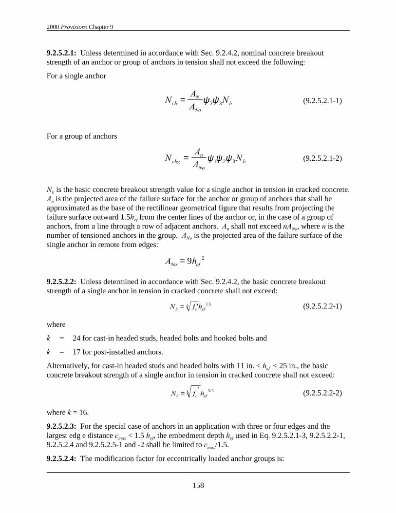
2000 Provisions Chapter 9
158
9.2.5.2.1: Unless determined in accordance with Sec. 9.2.4.2, nominal concrete breakoutstrength of an anchor or group of anchors in tension shall not exceed the following:
For a single anchor
(9.2.5.2.1-1)NA
ANcb
N
Nob= ψ ψ2 3
For a group of anchors
(9.2.5.2.1-2)NA
ANcbg
n
Nob= ψ ψ ψ1 2 3
Nb is the basic concrete breakout strength value for a single anchor in tension in cracked concrete. An is the projected area of the failure surface for the anchor or group of anchors that shall beapproximated as the base of the rectilinear geometrical figure that results from projecting thefailure surface outward 1.5hef from the center lines of the anchor or, in the case of a group ofanchors, from a line through a row of adjacent anchors. An shall not exceed nANo, where n is thenumber of tensioned anchors in the group. ANo is the projected area of the failure surface of thesingle anchor in remote from edges:
A hNo ef= 9 2
9.2.5.2.2: Unless determined in accordance with Sec. 9.2.4.2, the basic concrete breakoutstrength of a single anchor in tension in cracked concrete shall not exceed:
(9.2.5.2.2-1)N f hb ck
ef= ′ 1 5.
where
k = 24 for cast-in headed studs, headed bolts and hooked bolts and
k = 17 for post-installed anchors.
Alternatively, for cast-in headed studs and headed bolts with 11 in. < hef < 25 in., the basicconcrete breakout strength of a single anchor in tension in cracked concrete shall not exceed:
(9.2.5.2.2-2)N f hb ck
ef= ′ 5 3/
where k = 16.
9.2.5.2.3: For the special case of anchors in an application with three or four edges and thelargest edg e distance cmax < 1.5 hef, the embedment depth hef used in Eq. 9.2.5.2.1-3, 9.2.5.2.2-1,9.2.5.2.4 and 9.2.5.2.5-1 and -2 shall be limited to cmax/1.5.
9.2.5.2.4: The modification factor for eccentrically loaded anchor groups is:
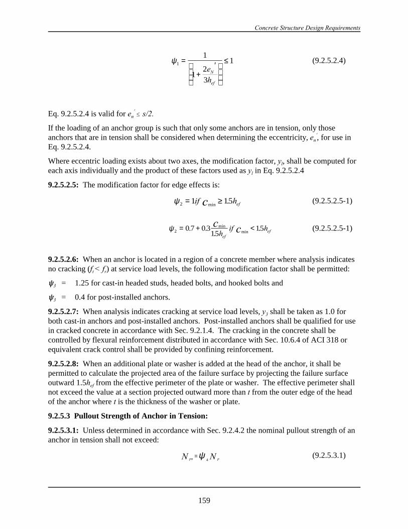
Concrete Structure Design Requirements
159
(9.2.5.2.4)ψ1
1
12
3
1=
+′
≤e
hN
ef
Eq. 9.2.5.2.4 is valid for en! # s/2.
If the loading of an anchor group is such that only some anchors are in tension, only thoseanchors that are in tension shall be considered when determining the eccentricity, en
!, for use inEq. 9.2.5.2.4.
Where eccentric loading exists about two axes, the modification factor, yl, shall be computed foreach axis individually and the product of these factors used as yl in Eq. 9.2.5.2.4
9.2.5.2.5: The modification factor for edge effects is:
(9.2.5.2.5-1)ψ2 1 15= ≥if hc efmin.
(9.2.5.2.5-1)ψ 2 0 7 0 315
15= + <. ..
.minmin
c chif h
efef
9.2.5.2.6: When an anchor is located in a region of a concrete member where analysis indicatesno cracking (ft < fr) at service load levels, the following modification factor shall be permitted:
R3 = 1.25 for cast-in headed studs, headed bolts, and hooked bolts and
R3 = 0.4 for post-installed anchors.
9.2.5.2.7: When analysis indicates cracking at service load levels, y3 shall be taken as 1.0 forboth cast-in anchors and post-installed anchors. Post-installed anchors shall be qualified for usein cracked concrete in accordance with Sec. 9.2.1.4. The cracking in the concrete shall becontrolled by flexural reinforcement distributed in accordance with Sec. 10.6.4 of ACI 318 orequivalent crack control shall be provided by confining reinforcement.
9.2.5.2.8: When an additional plate or washer is added at the head of the anchor, it shall bepermitted to calculate the projected area of the failure surface by projecting the failure surfaceoutward 1.5hef from the effective perimeter of the plate or washer. The effective perimeter shallnot exceed the value at a section projected outward more than t from the outer edge of the headof the anchor where t is the thickness of the washer or plate.
9.2.5.3 Pullout Strength of Anchor in Tension:
9.2.5.3.1: Unless determined in accordance with Sec. 9.2.4.2 the nominal pullout strength of ananchor in tension shall not exceed:
(9.2.5.3.1)pn pN N=
4ψ
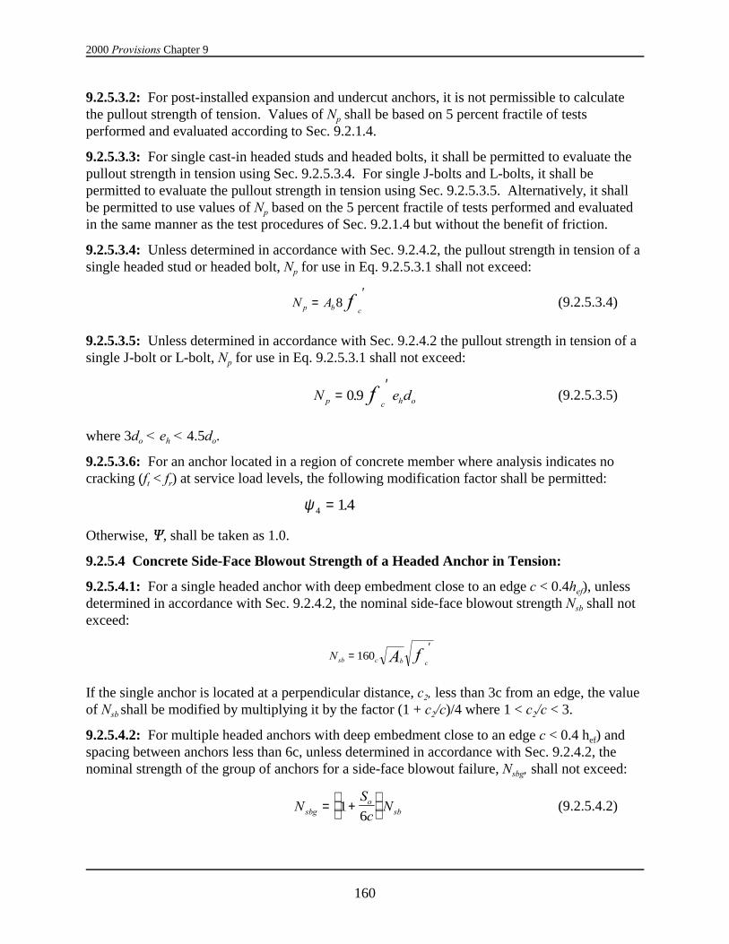
2000 Provisions Chapter 9
160
9.2.5.3.2: For post-installed expansion and undercut anchors, it is not permissible to calculatethe pullout strength of tension. Values of Np shall be based on 5 percent fractile of testsperformed and evaluated according to Sec. 9.2.1.4.
9.2.5.3.3: For single cast-in headed studs and headed bolts, it shall be permitted to evaluate thepullout strength in tension using Sec. 9.2.5.3.4. For single J-bolts and L-bolts, it shall bepermitted to evaluate the pullout strength in tension using Sec. 9.2.5.3.5. Alternatively, it shallbe permitted to use values of Np based on the 5 percent fractile of tests performed and evaluatedin the same manner as the test procedures of Sec. 9.2.1.4 but without the benefit of friction.
9.2.5.3.4: Unless determined in accordance with Sec. 9.2.4.2, the pullout strength in tension of asingle headed stud or headed bolt, Np for use in Eq. 9.2.5.3.1 shall not exceed:
(9.2.5.3.4)N Ap b cf=
′8
9.2.5.3.5: Unless determined in accordance with Sec. 9.2.4.2 the pullout strength in tension of asingle J-bolt or L-bolt, Np for use in Eq. 9.2.5.3.1 shall not exceed:
(9.2.5.3.5)N e dp c h of=′
0 9.
where 3do < eh < 4.5do.
9.2.5.3.6: For an anchor located in a region of concrete member where analysis indicates nocracking (ft < fr) at service load levels, the following modification factor shall be permitted:
ψ 4 14= .
Otherwise, Q, shall be taken as 1.0.
9.2.5.4 Concrete Side-Face Blowout Strength of a Headed Anchor in Tension:
9.2.5.4.1: For a single headed anchor with deep embedment close to an edge c < 0.4hef), unlessdetermined in accordance with Sec. 9.2.4.2, the nominal side-face blowout strength Nsb shall notexceed:
Nsb c b cA f=′
160
If the single anchor is located at a perpendicular distance, c2, less than 3c from an edge, the valueof Nsb shall be modified by multiplying it by the factor (1 + c2/c)/4 where 1 < c2/c < 3.
9.2.5.4.2: For multiple headed anchors with deep embedment close to an edge c < 0.4 hef) andspacing between anchors less than 6c, unless determined in accordance with Sec. 9.2.4.2, thenominal strength of the group of anchors for a side-face blowout failure, Nsbg, shall not exceed:
(9.2.5.4.2)NS
cNsbg
osb= +
1
6

Concrete Structure Design Requirements
161
where so is the spacing of the outer anchors along the edge in the group and Nsb is obtained fromEq. 9.2.5.4.1 without the modification for a perpendicular edge distance.
9.2.6 Design Requirements for Shear Loading:
9.2.6.1 Steel Strength of Anchor in Shear:
9.2.6.1.1: The nominal strength of anchor in shear as governed by steel, Vs, shall be evaluated bycalculations based on the properties of the anchor material and the physical dimensions of theanchor. Alternatively, it shall be permitted to use values based on the 5 percent fractile of testresults to establish values of Vs.
9.2.6.1.2: Unless determined by the 5 percent fractile of test results, nominal strength of ananchor or group of anchors in shear shall not exceed the following:
a. For anchor material with a well-defined yield point:
(9.2.6.1.2-1)V nA fs se y=
b. For cast-in anchors without a well defined yield point:
(9.2.6.1.2-2)V n A fs se ut= 0 6.
where fut shall not be taken greater than 125,000 psi.
c. For post-installed anchors without a well-defined yield point:
(9.2.6.1.2-3)( )V n A f A fs se ut sl utsl= +0 6 0 4. .
where fut shall be taken greater than 125,000 psi.
9.2.6.1.3: Where anchors are used with built-up grout pads, the nominal strengths of Sec.9.2.6.1.2 shall be reduced by 20 percent.
9.2.6.2: Concrete Breakout Strength of Anchors in Shear:
9.2.6.2.1: Unless determined in accordance with Sec. 9.2.4.2, nominal concrete breakoutstrength in shear of an anchor or group of anchors shall not exceed the following:
For shear force perpendicular to the edge on a single anchor:
(9.2.6.2.1-1)VA
AVb
V
Vob= ψ ψ6 7
For shear force perpendicular to the edge on a group of anchors:
(9.2.6.2.1-2)VA
AVcbg
v
vob= ψ ψ ψ5 6 7
For shear force parallel to an edge, Vch or Vcbg shall be permitted to be twice the value for theforce determined from Eq. 9.2.6.2.1-1 or 9.2.6.2.1-2- respectively, with R6 taken equal to 1.
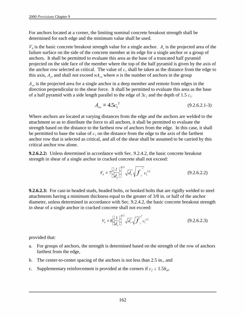
2000 Provisions Chapter 9
162
For anchors located at a corner, the limiting nominal concrete breakout strength shall bedetermined for each edge and the minimum value shall be used.
Vb is the basic concrete breakout strength value for a single anchor. Av is the projected area of thefailure surface on the side of the concrete member at its edge for a single anchor or a group ofanchors. It shall be permitted to evaluate this area as the base of a truncated half pyramidprojected on the side face of the member where the top of the half pyramid is given by the axis ofthe anchor row selected as critical. The value of c1 shall be taken as the distance from the edge tothis axis, Ay, and shall not exceed nAvo where n is the number of anchors in the group
Avo is the projected area for a single anchor in a deep member and remote from edges in thedirection perpendicular to the shear force. It shall be permitted to evaluate this area as the baseof a half pyramid with a side length parallel to the edge of 3c1 and the depth of 1.5 c1.
(9.2.6.2.1-3)A cvo = 4 5 12.
Where anchors are located at varying distances from the edge and the anchors are welded to theattachment so as to distribute the force to all anchors, it shall be permitted to evaluate thestrength based on the distance to the farthest row of anchors from the edge. In this case, it shallbe permitted to base the value of c1 on the distance from the edge to the axis of the farthestanchor row that is selected as critical, and all of the shear shall be assumed to be carried by thiscritical anchor row alone.
9.2.6.2.2: Unless determined in accordance with Sec. 9.2.4.2, the basic concrete breakoutstrength in shear of a single anchor in cracked concrete shall not exceed:
(9.2.6.2.2)Vl
dd cb
oo c
f=
′7
0 2
11 5
.
.
9.2.6.2.3: For cast-in headed studs, headed bolts, or hooked bolts that are rigidly welded to steelattachments having a minimum thickness equal to the greater of 3/8 in. or half of the anchordiameter, unless determined in accordance with Sec. 9.2.4.2, the basic concrete breakout strengthin shear of a single anchor in cracked concrete shall not exceed:
(9.2.6.2.3)Vd
d cbo
o cf=
′8
10 2
11 5
.
.
provided that:
a. For groups of anchors, the strength is determined based on the strength of the row of anchorsfarthest from the edge,
b. The center-to-center spacing of the anchors is not less than 2.5 in., and
c. Supplementary reinforcement is provided at the corners if c2 # 1.5hef.
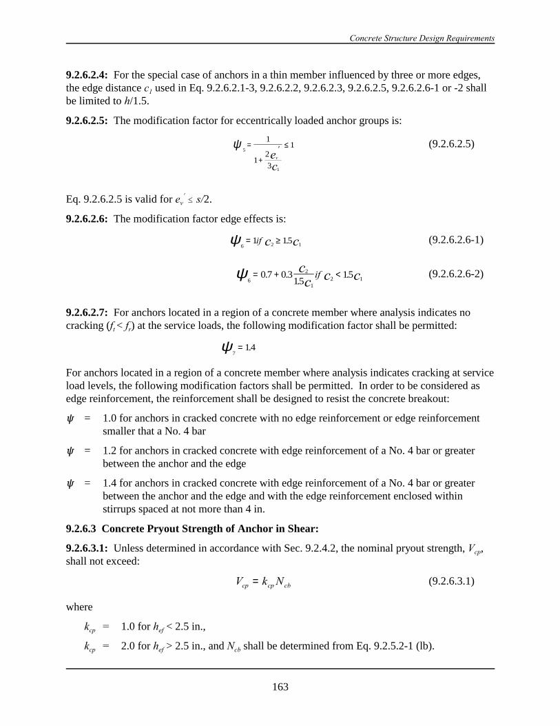
Concrete Structure Design Requirements
163
9.2.6.2.4: For the special case of anchors in a thin member influenced by three or more edges,the edge distance c1 used in Eq. 9.2.6.2.1-3, 9.2.6.2.2, 9.2.6.2.3, 9.2.6.2.5, 9.2.6.2.6-1 or -2 shallbe limited to h/1.5.
9.2.6.2.5: The modification factor for eccentrically loaded anchor groups is:
(9.2.6.2.5)5
1
1
12
3
1ψ =
+′ ≤
vec
Eq. 9.2.6.2.5 is valid for ev! # s/2.
9.2.6.2.6: The modification factor edge effects is:
(9.2.6.2.6-1)6 2 1
1 15ψ = ≥if c c.
(9.2.6.2.6-2)6
2
12 1
0 7 0 315
15ψ = + <. ..
.cc c cif
9.2.6.2.7: For anchors located in a region of a concrete member where analysis indicates nocracking (ft < fr) at the service loads, the following modification factor shall be permitted:
714ψ = .
For anchors located in a region of a concrete member where analysis indicates cracking at serviceload levels, the following modification factors shall be permitted. In order to be considered asedge reinforcement, the reinforcement shall be designed to resist the concrete breakout:
R = 1.0 for anchors in cracked concrete with no edge reinforcement or edge reinforcementsmaller that a No. 4 bar
R = 1.2 for anchors in cracked concrete with edge reinforcement of a No. 4 bar or greaterbetween the anchor and the edge
R = 1.4 for anchors in cracked concrete with edge reinforcement of a No. 4 bar or greaterbetween the anchor and the edge and with the edge reinforcement enclosed withinstirrups spaced at not more than 4 in.
9.2.6.3 Concrete Pryout Strength of Anchor in Shear:
9.2.6.3.1: Unless determined in accordance with Sec. 9.2.4.2, the nominal pryout strength, Vcp,shall not exceed:
(9.2.6.3.1)V k Ncp cp cb=
where
kcp = 1.0 for hef < 2.5 in.,
kcp = 2.0 for hef > 2.5 in., and Ncb shall be determined from Eq. 9.2.5.2-1 (lb).
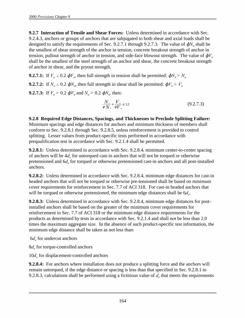
2000 Provisions Chapter 9
164
9.2.7 Interaction of Tensile and Shear Forces: Unless determined in accordance with Sec.9.2.4.3, anchors or groups of anchors that are subjugated to both shear and axial loads shall bedesigned to satisfy the requirements of Sec. 9.2.7.1 through 9.2.7.3. The value of NNn shall bethe smallest of shear strength of the anchor in tension, concrete breakout strength of anchor intension, pullout strength of anchor in tension, and side-face blowout strength. The value of NVn
shall be the smallest of the steel strength of an anchor and shear, the concrete breakout strengthof anchor in shear, and the pryout strength.
9.2.7.1: If Vu # 0.2 NVn, then full strength in tension shall be permitted: NNn > Nu
9.2.7.2: If Nu # 0.2 NNn, then full strength in shear shall be permitted: NVn > Vu
9.2.7.3: If Vu > 0.2 NVn and Nu > 0.2 NNn, then:
(9.2.7.3)u
n
u
n
NN
VVφ φ
+ ≤ 12.
9.2.8 Required Edge Distances, Spacings, and Thicknesses to Preclude Splitting Failure: Minimum spacings and edge distances for anchors and minimum thickness of members shallconform to Sec. 9.2.8.1 through Sec. 9.2.8.5, unless reinforcement is provided to controlsplitting. Lesser values from product-specific tests performed in accordance with prequalification test in accordance with Sec. 9.2.1.4 shall be permitted.
9.2.8.1: Unless determined in accordance with Sec. 9.2.8.4, minimum center-to-center spacingof anchors will be 4do for untorqued cast-in anchors that will not be torqued or otherwisepretensioned and 6do for torqued or otherwise pretensioned cast-in anchors and all post-installedanchors.
9.2.8.2: Unless determined in accordance with Sec. 9.2.8.4, minimum edge distances for cast-inheaded anchors that will not be torqued or otherwise pre-tensioned shall be based on minimumcover requirements for reinforcement in Sec. 7.7 of ACI 318. For cast-in headed anchors thatwill be torqued or otherwise pretensioned, the minimum edge distances shall be 6do.
9.2.8.3: Unless determined in accordance with Sec. 9.2.8.4, minimum edge distances for post-installed anchors shall be based on the greater of the minimum cover requirements forreinforcement in Sec. 7.7 of ACI 318 or the minimum edge distance requirements for theproducts as determined by tests in accordance with Sec. 9.2.1.4 and shall not be less than 2.0times the maximum aggregate size. In the absence of such product-specific test information, theminimum edge distance shall be taken as not less than:
6do for undercut anchors
8do for torque-controlled anchors
10do for displacement-controlled anchors
9.2.8.4: For anchors where installation does not produce a splitting force and the anchors willremain untorqued, if the edge distance or spacing is less than that specified in Sec. 9.2.8.1 to9.2.8.3, calculations shall be performed using a fictitious value of do that meets the requirements

Concrete Structure Design Requirements
165
of Sec.9.2.8.1 to 9.2.8.3. Calculated forces applied to the anchor shall be limited to valuescorresponding to an anchor having the fictitious diameter.
9.2.8.5: The value of hef for an expansion or undercut post-installed anchor shall not exceed thegreater of either two thirds of the member thickness or the member thickness less than 4 in.
9.2.8.6: Project drawings and project specifications shall specify use of anchors with a minimumedge distance as assumed in design.
9.2.9 Installation of Anchors: Anchors shall be installed in accordance with the projectdrawings and specifications.
9.3 CLASSIFICATION OF SHEAR WALLS: Structural concrete shear walls that resistseismic forces shall be classified in accordance with Sec. 9.3.1 through 9.3.4.
9.3.1 Ordinary Plain Concrete Shear Walls: Ordinary plain concrete shear walls are wallsconforming to the requirements of Chapter 22 of ACI 318.
9.3.2 Detailed Plain Concrete Shear Walls: Detailed plain concrete shear walls are wallsabove the base conforming to the requirements of Chapter 22 of ACI 318 and containingreinforcement as follows:
Vertical reinforcement of at least 0.20 in.2 (129 mm2) in cross-sectional area shall be providedcontinuously from support to support at each corner, at each side of each opening, and at the endsof walls. The continuous vertical bar required by Sec. 22.6.6.5 of ACI 318 shall be provided.
Horizontal reinforcement at least 0.20 in.2 (129 mm2) in cross-sectional area shall be provided:
a. Continuously at structurally connected roof and floor levels and at the top of walls,
b. At the bottom of load-bearing walls or in the top of foundations when doweled to the wall,and
c. At a maximum spacing of 120 inches (3050 mm).
Reinforcement at the top and bottom of openings, when used in determining the maximumspacing specified in Item c above, shall be continuous in the wall.
Basement, foundation, or other walls below the base shall be reinforced as required by Sec.22.6.6.5 of ACI 318.
9.3.2.1 Ordinary Reinforced Concrete Shear Walls: Ordinary reinforced concrete shearwalls are walls conforming to the requirements of ACI 318 exclusive of Chapters 21 and 22.
9.3.2.2 Special Reinforced Concrete Shear Walls: Special reinforced concrete shear wallsare walls conforming to the requirements of ACI 318 in addition to the requirements for ordinaryreinforced concrete shear walls.
9.4 SEISMIC DESIGN CATEGORY A: Structures assigned to Seismic Design Category Amay be of any construction permitted in ACI 318 and the Provisions.
9.5 SEISMIC DESIGN CATEGORY B: Structures assigned to Seismic Design Category Bshall conform to all the requirements for Seismic Design Category A and the additional
2000 Provisions Chapter 9
166
requirements for Seismic Design Category B of this section and in other chapters of the Provi-sions.
9.5.1 Ordinary Moment Frames: Flexural members of ordinary moment frames forming partof the seismic-force-resisting system shall be designed in accordance with Sec. 7.13.2 of ACI 318and at least two main flexural reinforcing bars shall be provided continuously top and bottomthroughout the beams, through or developed within exterior columns or boundary elements.
Columns of ordinary moment frames having a clear height to maximum plan dimension ratio of5 or less shall be designed for shear in accordance with Sec. 21.10.3 of ACI 318.
9.6 SEISMIC DESIGN CATEGORY C: Buildings assigned to Seismic Design Category Cshall conform to all requirements for Seismic Design Category B and to the additionalrequirements for Seismic Design Category C of this section an in other chapters of the Provi-sions.
9.6.1 Seismic-Force-Resisting Systems: Seismic-force-resisting systems shall conform to Sec.9.6.1.1 and Sec. 9.6.1.2.
9.6.1.1 Moment Frames: All moment frames that are part of the seismic-force-resisting systemshall be intermediate moment frames or special moment frames.
9.6.1.2 Shear Walls: All shear walls that are part of the seismic-force-resisting system shall beordinary reinforced concrete shear walls conforming to Sec. 9.3.3 or special reinforced concreteshear walls conforming to Sec. 9.3.4.
9.6.2 Discontinuous Members: Columns supporting reactions from discontinuous stiffmembers such as walls shall be designed for special load combinations in Sec. 5.2.7.1 and shallbe provided with transverse reinforcement at the spacing so as defined in Sec. 21.10.5.1 of ACI318 over their full height beneath the level at which the discontinuity occurs. This transversereinforcement shall be extended above and below the column as required in Sec. 21.4.4.5 of ACI318.
9.6.3 Plain Concrete: Structural plain concrete members in buildings assigned to SeismicDesign Category C shall conform to ACI 318 and the additional requirements and limitations ofthis section.
9.6.3.1 Walls: Structural plain concrete walls are not permitted in structures assigned to SeismicDesign Category C.
Exception: Structural plain concrete basement, foundation, or other walls below thebase are permitted in detached one- and two-family dwellings three stories or less inheight constructed with stud bearing walls. Such walls shall have reinforcement inaccordance with Sec. 22.6.6.5 of ACI 318.
9.6.3.2 Footings: Isolated footings of plain concrete supporting pedestals or columns arepermitted provided the projection of the footing beyond the face of the supported member doesnot exceed the footing thickness.
Exception: In detached one- and two-family dwellings three stories or less in height oflight-frame construction, structural plain concrete basement walls, foundation, or other
Concrete Structure Design Requirements
167
walls below the basement shall be permitted. Such concrete walls shall have reinforce-ment in accordance with Sec. 22.6.6.5 of ACI 318.
Plain concrete footings supporting walls shall be provided with no less than two continuouslongitudinal reinforcing bars. Bars shall not be smaller than No. 4 (#13) and shall have a totalarea of not less than 0.002 times the gross cross-sectional area of the footing. For footings thatexceed 8 in. in thickness, a minimum of one bar shall be provided at the top and bottom of thefooting. For foundation systems consisting of plain concrete footing and plain concretestemwall, a minimum of one bar shall be provided at the top of the stemwall and at the bottomthe footing. Continuity of reinforcement shall be provided at corners and intersections.
Exceptions:
1. In detached one- and two-family dwellings three stories or less in height andconstructed with stud bearing walls, plain concrete footings supporting walls shallbe permitted without longitudinal reinforcement.
2. Where a slab-on-ground is cast monolithically with the footing, one No. 5 (#16) baris permitted to be located at either the top or bottom of the footing.
9.6.3.3 Pedestals: Plain concrete pedestals shall not be used to resist lateral seismic forces.
9.6.4 Anchor Bolts in the Tops of Columns: Anchor bolts that are set in the top of a columnshall be provided with ties that completely enclose at least four longitudinal column bars. Thereshall be at least two No. 4 (#13) or three No. 3 (#10) ties within 5 inches of the top of thecolumn. The ties shall have hooks on each free end that comply with Sec. 7.1.3 of ACI 318.
9.7 SEISMIC DESIGN CATEGORIES D, E, OR F: Structures assigned to Seismic DesignCategory D, E, or F shall conform to all of the requirements for Seismic Design Category C andto the additional requirements in this section.
9.7.1 Seismic-Force-Resisting Systems: Seismic-force-resisting systems shall conform to Sec.9.7.1.1 and Sec. 9.7.1.2.
9.7.1.1 Moment Frames: All moment frames that are part of the seismic-force-resisting system,regardless of height, shall be special moment frames.
9.7.1.2 Shear Walls: All shear walls that are part of the seismic-force-resisting system shall bespacial reinforced concrete shear walls conforming to Sec. 9.3.4.
9.7.2 Frame Members Not Proportioned to Resist Forces Induced by Earthquake Motions: All frame members assumed not to contribute to lateral forces resistance shall conform to Sec.21.9 of ACI 318 is modified by Sec. 9.1.1.11 of this chapter.
168
Appendix to Chapter 9
REINFORCED CONCRETE DIAPHRAGMS CONSTRUCTED USINGUNTOPPED PRECAST CONCRETE ELEMENTS
Preface: Reinforced concrete diaphragms constructed using untopped precast concreteelements are permitted in the body of the 2000 NEHRP Recommended Provisions forSeismic Design Categories A, B, and C but not for Categories D, E, and F. For thelatter the precast elements must be topped and the topping designed as the diaphragm. For resisting seismic forces, a composite-topping slab cast in place on precast concreteelements must have a thickness no less than 2 in. and a topping slab not relying oncomposite action with the precast elements must have a thickness not less than 2-1/2 in.
There are two principal reasons why a framework for the design of untopped dia-phragms for Seismic Design Categories D, E, and F may be desirable. One relates tothe performance of topping slab diaphragms in recent earthquakes and the other todurability considerations. The 1997 Provisions incorporated ACI 318-95 for which theprovisions for topping slab diaphragms on precast elements were essentially the sameas those in ACI 318-89. In the 1994 Northridge earthquake, performance was poor forstructures where demands on the topping slab diaphragms on precast elements weremaximized and the structures had been designed using ACI 318-89. The toppingcracked along the edges of the precast elements and the welded wire reinforcementcrossing those cracks fractured. The diaphragms became the equivalent of anuntopped diaphragm with the connections between precast concrete elements, theconnectors, and the chords not detailed for that condition. Another problem foundwith topping slab diaphragms was that the chords often took the large diameter bars,grouped closely together at the topping slab edge. Under severe loading, these uncon-fined chord bars lost bond with the concrete and with it, ability to transfer seismicforces.
The 2000 NEHRP incorporates ACI 318-99 which recognizes that for topping slabdiaphragms a controlling condition is the in-plane shear in concrete along the edges ofthe precast elements. Ductility is provided by requiring that the topping slab reinforce-ment crossing the edges be spaced at not less than 10 in. on center. While thoserequirements are based on best available engineering judgement and evidence, theyhave not yet been proven to provide adequate safety either by laboratory testing orfield performance. Due to the dimensions of the precast element relative to thethickness of the topping slab, it may well be prudent to have seismic provisions fordiaphragms incorporating precast elements controlled by untopped diaphragmconsiderations and to have those provisions modified for topped diaphragms. Further,in geographic areas where corrosive environments are a significant concern, theconstruction of un-topped diaphragms using “pretopped” precast elements rather thantopped elements is desirable.

Concrete Structure Design Requirements
169
This appendix provides a compilation of current engineering judgment on a frameworkfor seismic provisions for untopped diaphragms. That framework does not, however,adequately address all the concerns needed for its incorporation into the body of theProvisions. This appendix proposes that a diaphragm composed of untopped elementsbe designed to remain elastic, and that the connectors be designed for limited ductilityin the event that design forces are exceeded during earthquake response and someinelastic action occurs when the demands on the diaphragm are maximized. Bycontrast, for all other systems for Seismic Design Categories D, E and F, the philosophyof the 2000 NEHRP is to require significant ductility. For the approach of this appen-dix, critical issues are how best to define:
1. The design forces for the diaphragm so that they are large enough to result inessentially elastic behavior when the demands on the diaphragm are maximized orwhether that criterion is even achievable;
2. The relation between the response of the diaphragm, its dimensions, and theductility demands on the connectors;
3. The ductility changes that occur for connectors under various combinations of in-plane and out-of-plane shear forces and tensile and compressive forces;
4. The boundary conditions necessary for testing and for application of the loadingfor the validation testing of connectors; and
5. The constraints on connector performance imposed by their size relative to the sizeof the diaphragm elements.
The use of this appendix as a framework for laboratory testing, analyses of theperformance of diaphragms in past earthquakes, analytical studies, and trial designs, isencouraged. Users should also consult the Commentary for guidance and references. Please direct all feedback on this appendix and its commentary to the BSSC.
9A.1 Background: ACI 318-99 was significantly revised for structural diaphragms to add newdetailing provisions in response to the poor performance of some cast-in-place composite toppingslab diaphragms during the 1994 Northridge earthquake. New code and commentary Sec. 21.7and R21.7 were inserted into Chapter 21. In those provisions, cast-in-place composite toppingslabs and cast-in-place topping slab diaphragms are permitted but no mention is made ofuntopped precast diaphragms. The evidence from the recently completed PRESS 5-storybuilding test (PCI Journal, November-December 1999), from Italian and English tests (M. J.NM. Priestley, D. Sritharan, J. R. Connley, and S. Pampanin, “Preliminary Results and Conclu-sions from the PRESSS Five-Story Precast Concrete Test Building,” PCI Journal, Vol. 44, No.6, November-December 1999; K. S. Elliott, G. Davies, and W. Omar, “Experimental Hollow-cored Slabs Used as Horizontal Floor Diaphragms,” The Structural Engineer, Vol. 70, No. 10,May 1922, pp. 175-187; M. Menegotto, Seismic Diaphragm Behavior of Untopped Hollow-CoreFloors, Proceedings, FIP Congress, Washington, D. C., May 1994), and from the 1999 Turkeyearthquake is that such diaphragms can perform satisfactorily if they are properly detailed and ifthey and their connections remain elastic under the force levels the diaphragms experience. However, further additions are needed to the ACI 318 requirements to make that possible both in
2000 Provisions Chapter 9
170
terms of the forces for which diaphragms should be designed and the ductilities that should beinherent in connections as a second line of defense.
In this appendix, the untopped precast diaphragm is designed to remain elastic by requiring thatits design forces be based on Eq. 5.2.5.4 and be not less than a minimum value dependent uponthe seismic response coefficient, with both values multiplied by the overstrength and redundancyfactors associated with the seismic-force-resisting system. In addition, the connections arerequired to be able to perform in a ductile manner in the unlikely event that the diaphragm isforced to deform inelastically.
9A.2 References: The following references are to be considered part of this appendix to theextent referred to in this document:
ACI 318-99/ American Concrete Institute (ACI), Building Code Requirements for Struc-tural
ACI 318-99R Concrete, 1999
ACI ITG/T1.1 American Concrete Institute (ACI), Acceptance Criteria For MomentFrames, Based on Structural Testing ( An ACI Provisional Standard),ITG/T1.1, 1999
ATC-24 Applied Technology Council (ATC), Guidelines for Seismic Testing ofComponents of Steel Structures, ATC-24, 1992.
9A.3 Untopped Precast Diaphragms:
9A.3.1: An untopped precast floor or roof shall be permitted as a structural diaphragm providedSec. 9A.3.2 through 9A.3.3 are satisfied. Untopped diaphragms shall not be permitted instructures having plan irregularity Type 4 as defined in Provisions Table 5.2.3.2.
9A.3.2: Rational elastic models shall be used to determine the in-plane shear andtension/compression forces acting on connections that cross joints. For any given joint, theconnections shall resist the total shear and total moment acting on the joint according to anelastic distribution of stresses
9A.3.3: The diaphragm design force shall be not less than the force calculated from either of thefollowing two criteria:
1. Deo times the Fpx value calculated from Eq. 5.2.5.4 but not less than DeoCswpx.
2. A shear force corresponding to 1.25 times that for yielding of the seismic-force-resistingsystem calculated using a M value of unity.
The overstrength factor, eo, shall be that for the seismic-force-resisting system specified in Provisions Table 5.2.2 unless derived by analysis of the probable strength of the seismic-force-resisting system and shall not be taken as less than 1.25 times the yield strength of that system. The redundancy factor, D, shall be as specified in Sec. 5.2.4 and the seismic response coefficient,Cs, shall be that determined in accordance with Provisions Sec. 5.3.2.1.

Concrete Structure Design Requirements
171
9A.3.4: For diaphragms in buildings having plan irregularities Type 1a, 1b, 2 or 5 as defined inProvisions Table 5.2.3.2, the analysis required by Sec. 9A.3.3 shall explicitly include the effectof such irregularities as required by Provisions Sec. 5.2.6.
9A.3.5: Mechanical connections shall have design strength for the body of the connector greaterthan the factored forces determined in accordance with Sec. 9A.3.3 and 9A.3.4.
9A.3.6: Mechanical connections used at joints shall be shown by analysis and test results todevelop, under reversed cyclic loading, the capacity in shear, tension, compression, or a combination as required by the analysis specified in Sec. 9A.3.2. Testing of connections andevaluation of results shall be made in accordance with the principles specified in ACI ITG/T1.1and ATC-24. Connections shall develop for the specified loading ductility ratios equal to orgrater than 2.0. Embedments for connections shall be governed by steel yielding and not byfracture of concrete or welds.
9A.3.7: Connections shall be designed using the strength reduction factors N specified in ACI318-99 and ACI 318-99R. When the N factor is modified by Sec. 9.3.4 of ACI 318-99 and ACI318-99R, the modified value shall be used for the diaphragm connections.
9A.3.8: Where the design relies on friction in grouted joints for shear transfer across the joints,shear friction resistance shall be provided by mechanical connectors or reinforcement.
9A.3.9: Cast-in place strips shall be permitted in the end or edge regions of precast componentsas chords or collectors. These strips shall meet the requirements for topping slab diaphragms. The reinforcement in the strips shall conform to 21.7.8.2 and 21.7.8.3 of ACI 318-99 and ACI 318-99R.
9A.3.10: In satisfying the compatibility requirement of Provisions Sec. 5.2.2.4.3, the additionaldeformation that results from the diaphragm flexibility shall be considered. The assumedflexural and shear stiffness properties of the elements that are part of the seismic-force-resistingsystem shall not exceed one-half of the gross-section properties, unless a rational cracked-sectionanalysis is performed.
9A.3.11: Diaphragms shall have a quality assurance plan satisfying the requirements of Provisions Sec. 3.2.1.
9A.3.12: Ties to supporting members and bearing lengths shall satisfy the requirements fordesign force and geometry characteristics specified for the connections in ACI 318, Sec. 21.2.1.7as modified by Provisions Sec. 9.1.1.4.
173173
Chapter 10
COMPOSITE STEEL AND CONCRETESTRUCTURE DESIGN REQUIREMENTS
10.1 REFERENCE DOCUMENTS: The design, construction, and quality of composite steel andconcrete components that resist seismic forces shall conform to the relevant requirements of thefollowing references except as modified by the provisions of this chapter.
ACI 318 American Concrete Institute (ACI), Building Code Requirements for StructuralConcrete, 1999, excluding Appendix A (Alternate Design Method) and Chapter22 (Structural Plain Concrete) and making Appendix C (Alternative Load andStrength Reduction Factors) mandatory
AISC/LRFD American Institute of Steel Construction (AISC), Load and Resistance FactorDesign Specification for Structural Steel Buildings (LRFD), 1999
AISC Seismic American Institute of Steel Construction (AISC), Seismic Provisions forStructural Steel Buildings, including Supplement No. 1, July 1997, Parts I and II
AISI American Iron and Steel Institute (AISI), Specification for the Design of Cold-Formed Steel Structural Members, 1996, including Supplement 2000, excludingASD provisions
10.1.1: When using ACI 318, Appendix A and Chapter 22 are excluded and Appendix C ismandatory.
10.2 REQUIREMENTS: An R factor as set forth in Table 5.2.2 for the appropriate composite steeland concrete system is permitted when the structure is designed and detailed in accordance with theprovisions of AISC Seismic, Part II.
In Seismic Design Categories B and above, the design of such systems shall conform to therequirements of AISC Seismic, Part II. Composite structures are permitted in Seismic DesignCategories D and above, subject to the limitations in Table 5.2.2, when substantiating evidence isprovided to demonstrate that the proposed system will perform as intended by AISC Seismic Part II.. The substantiating evidence shall be subject to the approval of the authority having jurisdiction. Wherecomposite elements or connections are required to sustain inelastic deformations, the substantiatingevidence shall be based upon cyclic testing.
175175
Chapter 11
MASONRY STRUCTURE DESIGN REQUIREMENTS
11.1 GENERAL:
11.1.1 Scope: The design and construction of reinforced and plain (unreinforced) masonrycomponents and systems and the materials used therein shall comply with the requirements of thischapter.
11.1.2 Reference Documents: The designation and title of documents cited in this chapter are listedin this section.
ACI 318 American Concrete Institute (ACI), Building Code Requirements for StructuralConcrete, excluding Appendix A, 1999
ACI 530 American Concrete Institute (ACI), Building Code Requirements for Masonry Structures,ACI 530/ASCE 5/TMS 402, 1999
ACI 530.1 American Concrete Institute (ACI), Specifications for Masonry Structures, ACI530.1/ASCE 6/TMS 602, 1999
Compliance with specific provisions of ACI 530 is mandatory where required by this chapter.
11.1.3 Definitions:
Anchor: Metal rod, wire, bolt, or strap that secures masonry to its structural support.
Area:
Gross Cross-Sectional Area: The area delineated by the out-to-out specified dimensions ofmasonry in the plane under consideration.
Net Cross-Sectional Area: The area of masonry units, grout, and mortar crossed by the planeunder consideration based on out-to-out specified dimensions.
Bed Joint: The horizontal layer of mortar on which a masonry unit is laid.
Backing: The wall surface to which veneer is secured. The backing can be concrete, masonry, steelframing, or wood framing.
Cleanout: An opening to the bottom of a grout space of sufficient size and spacing to allow removal ofdebris.
Collar Joint: Vertical longitudinal joint between wythes of masonry or between masonry wythe andback-up construction which is permitted to be filled with mortar or grout.

2000 Provisions Chapter 11
176176
Column: An isolated vertical member whose horizontal dimension measured at right angles to thethickness does not exceed three times its thickness and whose height is at least three times its thickness.
Composite Masonry: Multiwythe masonry members acting with composite action.
Connector: A mechanical device (including anchors, wall ties, and fasteners) for joining two or morepieces, parts, or members.
Cover: Distance between surface of reinforcing bar and edge of member.
Detailed Plain Masonry Shear Wall: A masonry shear wall designed to resist lateral forcesneglecting stresses in reinforcement and designed in accordance with Sec. 11.10.2.
Dimension:
Actual Dimension: The measured dimension of a designated item (e.g., a designated masonry unitor wall).
Nominal Dimension: The specified dimension plus an allowance for the joints with which the unitsare to be laid. Nominal dimensions are usually given in whole numbers. Thickness is given first,followed by height and then length.
Specified Dimension: The dimension specified for the manufacture or construction of masonry,masonry units, joints, or any other component of a structure.
Effective Height: For braced members, the effective height is the clear height between lateralsupports and is used for calculating the slenderness ratio. The effective height for unbraced members iscalculated in accordance with engineering mechanics.
Effective Period: Fundamental period of the structure based on cracked stiffness.
Glass Unit Masonry: Nonload-bearing masonry composed of glass units bonded by mortar.
Head Joint: Vertical mortar joint between masonry units within the wythe at the time the masonryunits are laid.
Intermediate Reinforced Masonry Shear Wall: A masonry shear wall designed to resist lateralforces considering stresses in reinforcement and designed in accordance with Sec. 11.10.4.
Masonry Unit:
Hollow Masonry Unit: A masonry unit whose net cross-sectional area in every plane parallel tothe bearing surface is less than 75 percent of the gross cross-sectional area in the same plane.
Solid Masonry Unit: A masonry unit whose net cross-sectional area in every plane parallel to thebearing surface is 75 percent or more of the gross cross-sectional area in the same plane.
Ordinary Plain Masonry Shear Wall: A masonry shear wall designed to resist lateral forcesneglecting stresses in reinforcement and designed in accordance with Sec. 11.10.1.
Masonry Structure Design Requirements
177177
Ordinary Reinforced Masonry Shear Wall: A masonry shear wall designed to resist lateral forcesconsidering stresses in reinforcement and designed in accordance with Sec. 11.10.3.
Plain Masonry: Masonry in which the tensile resistance of the masonry is taken into considerationand the effects of stresses in reinforcement are neglected.
Plastic Hinge: The zone in a structural member in which the yield moment is anticipated to beexceeded under loading combinations that include earthquake.
Reinforced Masonry: Masonry construction in which reinforcement acts in conjunction with themasonry to resist forces.
Running Bond: The placement of masonry units such that head joints in successive courses arehorizontally offset at least one-quarter the unit length.
Special Reinforced Masonry Shear Wall: A masonry shear wall designed to resist lateral forcesconsidering stresses in reinforcement and designed in accordance with Sec. 11.10.5.
Specified: Required by construction documents.
Specified Compressive Strength of Masonry, : Required compressive strength (expressed asf )m
force per unit of net cross-sectional area) of the masonry. Whenever the quantity is under thef )m
radical sign, the square root of numerical value only is intended and the result has units of pounds persquare inch (MPa).
Stack Bond: Stack bond is other than running bond. Usually, the placement of units is such that thehead joints in successive courses are aligned vertically.
Stirrup: Shear reinforcement in a beam or flexural member.
Strength:
Design Strength: Nominal strength multiplied by a strength reduction factor.
Nominal Strength: Strength of a member or cross section calculated in accordance with theseprovisions before application of any strength reduction factors.
Required Strength: Strength of a member or cross section required to resist factored loads.
Tie:
Lateral Tie: Loop of reinforcing bar or wire enclosing longitudinal reinforcement.
Wall Tie: A connector that joins wythes of masonry walls together.
Veneer:
Masonry Veneer: A masonry wythe that provides the exterior finish of a wall system andtransfers out-of-plane load directly to a backing but that is not considered to add load-resistingcapacity to the wall system.
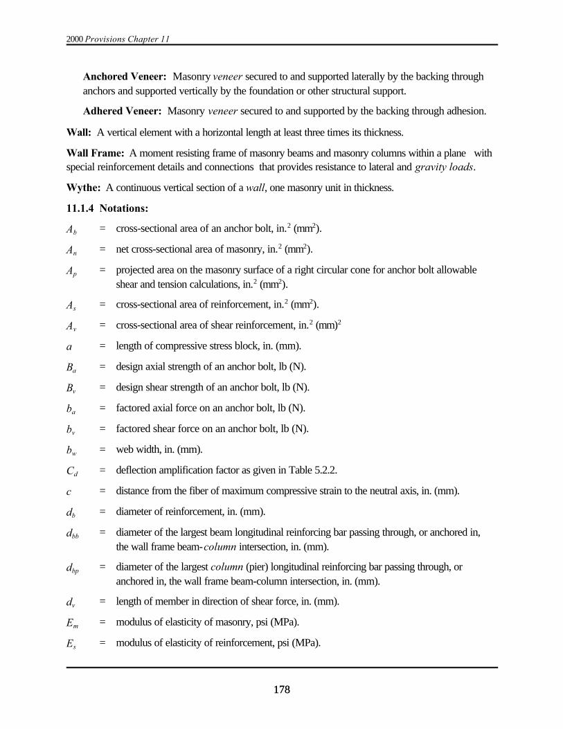
2000 Provisions Chapter 11
178178
Anchored Veneer: Masonry veneer secured to and supported laterally by the backing throughanchors and supported vertically by the foundation or other structural support.
Adhered Veneer: Masonry veneer secured to and supported by the backing through adhesion.
Wall: A vertical element with a horizontal length at least three times its thickness.
Wall Frame: A moment resisting frame of masonry beams and masonry columns within a plane withspecial reinforcement details and connections that provides resistance to lateral and gravity loads.
Wythe: A continuous vertical section of a wall, one masonry unit in thickness.
11.1.4 Notations:
Ab = cross-sectional area of an anchor bolt, in.2 (mm2).
An = net cross-sectional area of masonry, in.2 (mm2).
Ap = projected area on the masonry surface of a right circular cone for anchor bolt allowableshear and tension calculations, in.2 (mm2).
As = cross-sectional area of reinforcement, in.2 (mm2).
Av = cross-sectional area of shear reinforcement, in.2 (mm)2
a = length of compressive stress block, in. (mm).
Ba = design axial strength of an anchor bolt, lb (N).
Bv = design shear strength of an anchor bolt, lb (N).
ba = factored axial force on an anchor bolt, lb (N).
bv = factored shear force on an anchor bolt, lb (N).
bw = web width, in. (mm).
Cd = deflection amplification factor as given in Table 5.2.2.
c = distance from the fiber of maximum compressive strain to the neutral axis, in. (mm).
db = diameter of reinforcement, in. (mm).
dbb = diameter of the largest beam longitudinal reinforcing bar passing through, or anchored in,the wall frame beam-column intersection, in. (mm).
dbp = diameter of the largest column (pier) longitudinal reinforcing bar passing through, oranchored in, the wall frame beam-column intersection, in. (mm).
dv = length of member in direction of shear force, in. (mm).
Em = modulus of elasticity of masonry, psi (MPa).
Es = modulus of elasticity of reinforcement, psi (MPa).
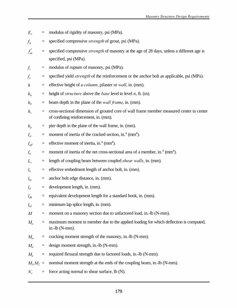
Masonry Structure Design Requirements
179179
Ev = modulus of rigidity of masonry, psi (MPa).
fg = specified compressive strength of grout, psi (MPa).
= specified compressive strength of masonry at the age of 28 days, unless a different age isf )mspecified, psi (MPa).
fr = modulus of rupture of masonry, psi (MPa).
fy = specified yield strength of the reinforcement or the anchor bolt as applicable, psi (MPa).
h = effective height of a column, pilaster or wall, in. (mm).
hn = height of structure above the base level to level n, ft. (m).
hb = beam depth in the plane of the wall frame, in. (mm).
hc = cross-sectional dimension of grouted core of wall frame member measured center to centerof confining reinforcement, in. (mm).
hp = pier depth in the plane of the wall frame, in. (mm).
Icr = moment of inertia of the cracked section, in.4 (mm4).
Ieff = effective moment of inertia, in.4 (mm4).
In = moment of inertia of the net cross-sectional area of a member, in.4 (mm4).
Lc = length of coupling beam between coupled shear walls, in. (mm).
lb = effective embedment length of anchor bolt, in. (mm).
lbe = anchor bolt edge distance, in. (mm).
ld = development length, in. (mm).
ldh = equivalent development length for a standard hook, in. (mm).
lld = minimum lap splice length, in. (mm).
M = moment on a masonry section due to unfactored load, in.-lb (N-mm).
Ma = maximum moment in member due to the applied loading for which deflection is computed,in.-lb (N-mm).
Mcr = cracking moment strength of the masonry, in.-lb (N-mm).
Md = design moment strength, in.-lb (N-mm).
Mu = required flexural strength due to factored loads, in.-lb (N-mm).
M1,M2 = nominal moment strength at the ends of the coupling beam, in.-lb (N-mm).
Nv = force acting normal to shear surface, lb (N).

2000 Provisions Chapter 11
180180
P = axial force on a masonry section due to unfactored loads, lb (N).
Pn = nominal axial load strength, lb (N).
Pu = required axial strength due to factored loads, lb (N).
r = radius of gyration, in. (mm).
S = section modulus based on net cross-sectional area of a wall, in.3 (mm3).
s = spacing of lateral reinforcement in wall frame members, in. (mm).
t = specified wall thickness dimension or least lateral dimension of a column, in. (mm).
V = shear on a masonry section due to unfactored loads, lb (N).
Vg = unfactored shear force due to gravity loads, lb (N).
Vm = shear strength provided by masonry, lb (N).
Vn = nominal shear strength, lb (N).
Vs = shear strength provided by shear reinforcement, lb (N).
Vu = required shear strength due to factored loads, lb (N).
) = design story drift as determined in Sec. 5.3.7.1, in. (mm).
)a = allowable story drift as specified in Sec. 5.2.8, in. (mm).
*max = the maximum displacement at level x, in. (mm).
D = ratio of the area of reinforcement to the net cross-sectional area of masonry in a planeperpendicular to the reinforcement.
Db = reinforcement ratio producing balanced strain conditions.
,mu = maximum usable compressive strain of masonry, in./in. (mm/mm).
N = strength reduction factor.
11.2 CONSTRUCTION REQUIREMENTS:
11.2.1 General: Masonry shall be constructed in accordance with the requirements of ACI 530.1.Materials shall conform to the requirements of the standards referenced in ACI 530.1.
11.2.2 Quality Assurance: Inspection and testing of masonry materials and construction shallcomply with the requirements of Chapter 3.
11.3 GENERAL REQUIREMENTS:
11.3.1 Scope: Masonry structures and components of masonry structures shall be designed inaccordance with the requirements of reinforced masonry design, plain (unreinforced) masonry design,empirical design or design for architectural components of masonry subject to the limitations of this

Masonry Structure Design Requirements
181181
section. All masonry walls, unless isolated on three sides from in-plane motion from the basic structuralsystem, shall be designed as shear walls. For design of glass-unit masonry and masonry veneer, seeSec. 11.12
11.3.2 Empirical Masonry Design: The requirements of Chapter 5 of ACI 530.1 shall apply to theempirical design of masonry.
11.3.3 Plain (Unreinforced) Masonry Design:
11.3.3.1: In the design of plain (unreinforced) masonry members, the flexural tensile strength ofmasonry units, mortar and grout in resisting design loads shall be permitted.
11.3.3.2: In the design of plain masonry members, stresses in reinforcement shall not be consideredeffective in resisting design loads.
11.3.3.3: Plain masonry members shall be designed to remain uncracked.
11.3.4 Reinforced Masonry Design: In the design of reinforced masonry members, stresses inreinforcement shall be considered effective in resisting design loads.
11.3.5 Seismic Design Category A: Structures assigned to Seismic Design Category A shallcomply with either the requirements of Sec. 11.3.2 (empirical masonry design), Sec. 11.3.3 (plainmasonry design), or Sec. 11.3.4 (reinforced masonry design).
11.3.6 Seismic Design Category B: Structures assigned to Seismic Design Category B shallconform to all the requirements for Seismic Design Category A and the lateral-force-resisting systemshall be designed in accordance with Sec. 11.3.3 or Sec. 11.3.4.
11.3.7 Seismic Design Category C: Structures assigned to Seismic Design Category C shallconform to the requirements for Seismic Design Category B and to the additional requirements of thissection.
11.3.7.1 Material Requirements: Structural clay load-bearing wall tile shall not be used as part ofthe basic structural system.
11.3.7.2 Masonry Shear Walls: Masonry shear walls shall comply with the requirements fordetailed plain masonry shear walls (Sec. 11.10.2), intermediate reinforced masonry shear walls(Sec. 11.10.4), or special reinforced masonry shear walls (Sec. 11.10.5).
11.3.7.3 Minimum Wall Reinforcement: Vertical reinforcement of at least 0.20 in.2 (129 mm2) incross-sectional area shall be provided continuously from support to support at each corner, at eachside of each opening, at the ends of walls, and at a maximum spacing of 4 feet (1219 mm) aparthorizontally throughout the walls. Horizontal reinforcement not less than 0.20 in.2 (129 mm2) in crosssection shall be provided as follows:
a. At the bottom and top of wall openings extending not less than 24 in. (610 mm) nor less than 40bar diameters past the opening,
b. Continuously at structurally connected roof and floor levels and at the top of walls,
2000 Provisions Chapter 11
182182
c. At the bottom of load-bearing walls or in the top of foundations when doweled to the wall, and
d. At maximum spacing of 120 in. (3048 mm) unless uniformly distributed joint reinforcement isprovided.
Reinforcement at the top and bottom of openings, when used in determining the maximum spacingspecified in Item d above, shall be continuous in the wall.
11.3.7.4 Stack Bond Construction: Where stack bond is used, the minimum horizontalreinforcement shall be 0.0007 times the gross cross-sectional area of the wall. This requirement shallbe satisfied with uniformly distributed joint reinforcement or with horizontal reinforcement spaced notover 48 in. (1219 mm) and fully embedded in grout or mortar.
11.3.7.5 Multiple Wythe Walls Not Acting Compositely: At least one wythe of a cavity wall shallbe reinforced masonry designed in accordance with Sec. 11.3.4. The other wythe shall be reinforcedwith a minimum of one W1.7 wire per 4-in. (102 mm) nominal wythe thickness and spaced at intervalsnot exceeding 16 in. (406 mm). The wythes shall be tied in accordance with ACI 530, Sec. 5.8.3.2.
11.3.7.6 Walls Separated from the Basic Structural System: Masonry walls, laterally supportedperpendicular to their own plane but otherwise structurally isolated on three sides from the basicstructural system, shall have minimum horizontal reinforcement of 0.0007 times the gross cross-sectional area of the wall. This requirement shall be satisfied with uniformly distributed jointreinforcement or with horizontal reinforcement spaced not over 48 in. (1219 mm) and fully embeddedin grout or mortar. Architectural components of masonry shall be exempt from this reinforcementrequirement.
11.3.7.7 Connections to Masonry Columns: Structural members framing into or supported bymasonry columns shall be anchored thereto. Anchor bolts located in the tops of columns shall be setentirely within the reinforcing cage composed of column bars and lateral ties. A minimum of two No. 4(13 mm) lateral ties shall be provided in the top 5 inches (127 mm) of the column.
11.3.8 Seismic Design Category D: Structures assigned to Seismic Design Category D shallconform to all of the requirements for Seismic Design Category C and the additional requirements ofthis section.
11.3.8.1 Material Requirements: Neither Type N mortar nor masonry cement shall be used as partof the basic structural system.
11.3.8.2 Masonry Shear Walls: Masonry shear walls shall comply with the requirements forspecial reinforced masonry shear walls (Sec. 11.10.5)
11.3.8.3 Minimum Wall Reinforcement: All walls shall be reinforced with both vertical andhorizontal reinforcement. The sum of the areas of horizontal and vertical reinforcement shall be at least0.002 times the gross cross-sectional area of the wall and the minimum area of reinforcement in eachdirection shall not be less than 0.0007 times the gross cross-sectional area of the wall. The spacing ofreinforcement shall not exceed 48 in. (1219 mm). Except for joint reinforcement, the bar size shall notbe less than a No. 3 (10-mm diameter). Reinforcement shall be continuous around wall corners and

Masonry Structure Design Requirements
183183
through intersections, unless the intersecting walls are separated. Only horizontal reinforcement that iscontinuous in the wall or element shall be included in computing the area of horizontal reinforcement. Reinforcement spliced in accordance with Sec. 11.4.5.6 shall be considered as continuous reinforce-ment. Architectural components of masonry shall be exempt from this reinforcement requirement.
11.3.8.4 Stack Bond Construction: Where masonry is laid in stack bond, the minimum amount ofhorizontal reinforcement shall be 0.0015 times the gross cross-sectional area of the wall. If open-endunits are used and grouted solid, the minimum amount of horizontal reinforcement shall be 0.0007 timesthe gross cross-sectional area of the wall. The maximum spacing of horizontal reinforcement shall notexceed 24 in. (610 mm). Architectural components of masonry shall be exempt from theserequirements.
11.3.8.5 Minimum Wall Thickness: The nominal thickness of masonry bearing walls shall not beless than 6 in. (152 mm). Nominal 4-in. (102 mm) thick load-bearing reinforced hollow clay unitmasonry walls with a maximum unsupported height or length to thickness ratio of 27 are permitted tobe used provided the net area unit strength exceeds 8,000 psi (55 MPa), units are laid in runningbond, bar sizes do not exceed No. 4 (13 mm) with not more than two bars or one splice in a cell, andjoints are not raked.
11.3.8.6 Minimum Column Reinforcement: Lateral ties in columns shall be spaced not more than8 in. (203 mm) on center for the full height of the column. Lateral ties shall be embedded in grout andshall be No. 3 (10 mm) or larger.
11.3.8.7 Minimum Column Dimension: The nominal dimensions of a masonry column shall not beless than 12 in. (305 mm).
11.3.8.8: Separation Joints: Where concrete abuts structural masonry and the joint between thematerials is not designed as a separation joint, the concrete shall be roughened so that the averageheight of aggregate exposure is 1/8 in. (3 mm) and shall be bonded to the masonry in accordance withthese requirements as if it were masonry. Vertical joints not intended to act as separation joints shall becrossed by horizontal reinforcement as required by Sec. 11.3.8.3.
11.3.9 Seismic Design Categories E and F: Structures assigned to Seismic Design Categories Eand F shall conform to the requirements of Seismic Design Category D and to the additionalrequirements and limitations of this section.
11.3.9.1 Material Requirements: Construction procedures or admixtures shall be used to minimizeshrinkage of grout and to maximize bond between reinforcement, grout, and units.
11.3.9.2 Masonry Shear Walls: Masonry shear walls shall comply with the requirements for specialreinforced masonry shear walls (Sec. 11.10.5).
11.3.9.3 Stack Bond Construction: Masonry laid in stack bond shall conform to the followingrequirements:
11.3.9.3.1: For masonry that is not part of the basic structural system, the minimum ratio of horizontalreinforcement shall be 0.0015 and the maximum spacing of horizontal reinforcement shall be 24 in. (610

2000 Provisions Chapter 11
184184
Em ' 750f )
m (11.3.10.2)
mm). For masonry that is part of the basic structural system, the minimum ratio of horizontalreinforcement shall be 0.0025 and the maximum spacing of horizontal reinforcement shall be 16 in. (406mm). For the purpose of calculating this ratio, joint reinforcement shall not be considered.
11.3.9.3.2: Reinforced hollow unit construction shall be grouted solid and all head joints shall bemade solid by the use of open end units.
11.3.10 Properties of Materials:
11.3.10.1 Steel Reinforcement Modulus of Elasticity: Unless otherwise determined by test, steelreinforcement modulus of elasticity, Es, shall be taken to be 29,000,000 psi (200,000 MPa).
11.3.10.2 Masonry Modulus of Elasticity: The modulus of elasticity of masonry. Em, shall bedetermined in accordance with Eq. 11.3.10.2 or shall be based on the modulus of elasticity determinedby prism test and taken between 0.05 and 0.33 times the masonry prism strength:
where Em = modulus of elasticity of masonry (psi) and = specified compressive strength off )m
masonry, psi. The metric equivalent of Eq. 11.3.10.2 is the same except that Em and are in MPa.f )m
11.3.10.3: The modulus of rigidity of masonry, Ev, shall be taken equal to 0.4 times the modulus ofelasticity of masonry, Em.
11.3.10.4 Masonry Compressive Strength:
11.3.10.4.1: The specified compressive strength of masonry, , shall equal or exceed 1,500 psi (10f )mMPa).
11.3.10.4.2: The value of used to determine nominal strength values in this chapter shall notf )m
exceed 4,000 psi (28 MPa) for concrete masonry and shall not exceed 6,000 psi (41 MPa) for claymasonry.
11.3.10.5 Modulus of Rupture:
11.3.10.5.1 Out-of-Plane Bending: The modulus of rupture, fr, for masonry elements subjected toout-of-plane bending shall be taken from Table 11.3.10.5.1.
TABLE 11.3.10.5.1 Modulus of Rupture for Out-of-Plane Bending (fr)

Masonry Structure Design Requirements
185185
Masonry type
Mortar types, psi (MPa)
Portland cement/lime
Masonry cement andair-entrained Portland
cement/lime
M or S N M or S N
Normal to bed joints Solid units Hollow unitsa
UngroutedFully grouted
80 (0.55)
50 (0.34)136 (0.94)
60 (0.41)
38 (0.26)116 (0.80)
48 (0.33)
30 (0.21)82 (0.57)
30 (0.21)
18 (0.12)52 (0.36)
Parallel to bed joints in running bond Solid units Hollow units
Ungrouted and partially groutedFully grouted (running bond masonry)
Parallel to bed joints in stack bond:
160 (1.10)
100 (0.69)160 (1.10)
0
120 (0.83)
76 (0.52)120 (0.83)
0
96 (0.66)
60 (0.41)96 (0.66)
0
60 (0.41)
38 (0.26)60 (0.41)
0
a For partially grouted masonry, modulus of rupture values shall be determined on the basis of linear interpolation betweenhollow units that are fully grouted and hollow units that are ungrouted based on amount (percentage) of grouting.
11.3.10.5.2 In-Plane Bending: The modulus of rupture, fr, for masonry elements subjected to in-plane forces shall be taken as 250 psi (1.7MPa). For grouted stack bond masonry, tension parallel tothe bed joints for in-plane bending shall be assumed to be resisted only by the continuous grout coresection.
11.3.10.6 Reinforcement Strength: Masonry design shall be based on a reinforcement strengthequal to the specified yield strength of reinforcement, fy, that shall not exceed 60,000 psi (400 MPa).
11.3.11 Section Properties:
11.3.11.1: Member strength shall be computed using section properties based on the minimum netbedded and grouted cores cross-sectional area of the member under consideration.
11.3.11.2: Section properties shall be based on specified dimensions.
11.3.12 Headed and Bent-Bar Anchor Bolts: All bolts shall be grouted in place with at least 1 in.(25 mm) grout between the bolt and masonry, except that 1/4-inch (6.4 mm) bolts may be placed inbed joints that are at least 1/2 in. (12.7 mm) in thickness.

2000 Provisions Chapter 11
186186
Ba ' 4 Ap f )
m(11.3.12.1-1)
Ba ' Ab fy (11.3.12.1-2)
Ap ' R2be (11.3.12.1.1-2)
Ap ' R2b (11.3.12.1.1-1)
11.3.12.1: The design axial strength, Ba, for headed anchor bolts embedded in masonry shall be thelesser of Eq. 11.3.12.1-1 (strength governed by masonry breakout) or Eq. 11.3.12.1-2 (strengthgoverned by steel):
where:
Ba = design axial strength of the headed anchor bolt, lb;
N = strength reduction factor where N = 0.5 for Eq. 11.3.12.1-1 and N = 0.9 for Eq.11.3.12.1-2;
Ap = projected area on the masonry surface of a right circular cone, in.2;
Ab = effective tensile stress area of the headed anchor bolt, in.2;
= specified compressive strength of the masonry, psi; andf )m
fy = specified yield strength of the headed anchor bolt, psi.
The metric equivalent of Eq. 11.3.12.1-1 is where Ba is in N, Ap is in mm2,Ba ' (0.33Ap f )m )
and is in MPa. The metric equivalent of Eq. 11.3.12.1-2 is the same except that Ba is in N, Ab is inf )m
mm2, and fy is in MPa.
11.3.12.1.1: The area Ap in Eq. 11.3.12.1-1 shall be the lesser of Eq. 11.3.12.1.1-1 or Eq.11.3.12.1.1-2:
where:
Ap = projected area on the masonry surface of a right circular cone, in.2;

Masonry Structure Design Requirements
187187
Ba ' 4 Ap f )
m (11.3.12.2-1)
Ba ' 1.5 f )
m edb % 200 lb % e % db db (11.3.12.2-3)
Ba ' Ab fy (11.3.12.2-2)
lb = effective embedment length of the headed anchor bolt, in.; and
lbe = anchor bolt edge distance, in..
The metric equivalents of Eq. 11.3.12.1.1-1 and Eq. 11.3.12.1.1-2 are the same except that Ap is inmm2 and lb and lbe are in mm.
Where the projected areas, Ap, of adjacent headed anchor bolts overlap, the projected area, Ap, ofeach bolt shall be reduced by one-half of the overlapping area. That portion of the projected areafalling in an open cell or core shall be deducted from the value of Ap calculated using Eq. 11.3.12.1.1-1or Eq. 11.3.12.1.1-2, whichever is less.
11.3.12.1.2: The effective embedment length of a headed bolt, lb , shall be the length of embedmentmeasured perpendicular from the surface of the masonry to the head of the anchor bolt.
11.3.12.1.3: The minimum effective embedment length of headed anchor bolts resisting axial forcesshall be 4 bolt diameters or 2 in. (51 mm), whichever is greater.
11.3.12.2: The design axial strength, Ba,,for bent-bar anchor bolts (J- or L-bolts) embedded inmasonry shall be the least of Eq. 11.3.12.2-1 (strength governed by masonry breakout), Eq.11.3.12.2-2 (strength governed by steel), or Eq. 11.3.12.2-3 (strength governed by anchor pullout):
where:
Ba = design axial strength of the bent-bar anchor bolt, lb;
N = strength reduction factor where N = 0.5 for Eq. 11.3.12.2-1, N = 0.9 for Eq. 11.3.12.2-2,and N = 0.65 for Eq. 11.3.12.2-3;
Ap = projected area on the masonry surface of a right circular cone, in.2;
Ab = effective tensile stress area of the bent-bar anchor bolt, in.2;
e = projected leg extension of bent-bar anchor bolt, measured from inside edge of anchor atbend to farthest point of anchor in the plane of the hook, in.; shall not be taken larger than2db for use in Eq. 11.3.12.2-3.
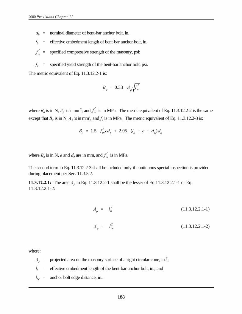
2000 Provisions Chapter 11
188188
Ba ' 0.33 Ap f )
m
Ba ' 1.5 f )
m edb % 2.05 (lb % e % db)db
Ap ' l 2b (11.3.12.2.1-1)
Ap ' l2be (11.3.12.2.1-2)
db = nominal diameter of bent-bar anchor bolt, in.
lb = effective embedment length of bent-bar anchor bolt, in.
= specified compressive strength of the masonry, psi;f )m
fy = specified yield strength of the bent-bar anchor bolt, psi.
The metric equivalent of Eq. 11.3.12.2-1 is:
where Ba is in N, Ap is in mm2, and is in MPa. The metric equivalent of Eq. 11.3.12.2-2 is the samef )m
except that Ba is in N, Ab is in mm2, and fy is in MPa. The metric equivalent of Eq. 11.3.12.2-3 is:
where Ba is in N, e and db are in mm, and is in MPa. f )m
The second term in Eq. 11.3.12.2-3 shall be included only if continuous special inspection is providedduring placement per Sec. 11.3.5.2.
11.3.12.2.1: The area Ap in Eq. 11.3.12.2-1 shall be the lesser of Eq.11.3.12.2.1-1 or Eq.11.3.12.2.1-2:
where:
Ap = projected area on the masonry surface of a right circular cone, in.2;
lb = effective embedment length of the bent-bar anchor bolt, in.; and
lbe = anchor bolt edge distance, in..
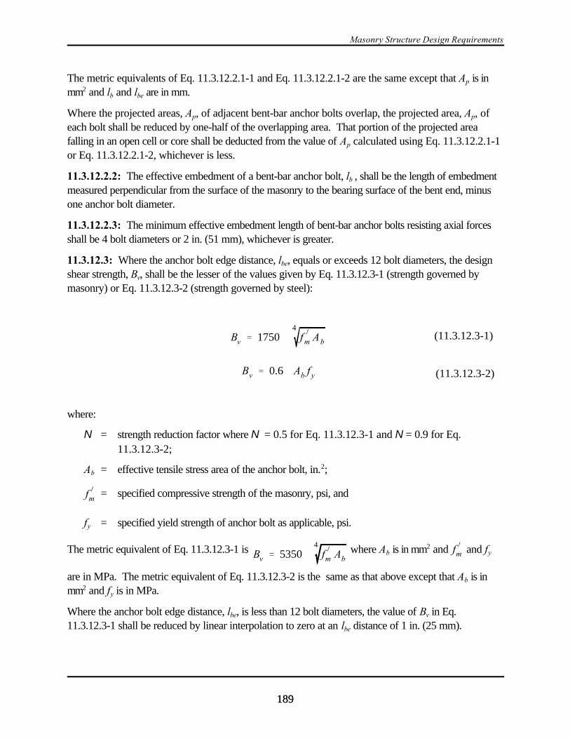
Masonry Structure Design Requirements
189189
Bv ' 17504
f)
m Ab(11.3.12.3-1)
Bv ' 0.6 Ab f y (11.3.12.3-2)
The metric equivalents of Eq. 11.3.12.2.1-1 and Eq. 11.3.12.2.1-2 are the same except that Ap is inmm2 and lb and lbe are in mm.
Where the projected areas, Ap, of adjacent bent-bar anchor bolts overlap, the projected area, Ap, ofeach bolt shall be reduced by one-half of the overlapping area. That portion of the projected areafalling in an open cell or core shall be deducted from the value of Ap calculated using Eq. 11.3.12.2.1-1or Eq. 11.3.12.2.1-2, whichever is less.
11.3.12.2.2: The effective embedment of a bent-bar anchor bolt, lb , shall be the length of embedmentmeasured perpendicular from the surface of the masonry to the bearing surface of the bent end, minusone anchor bolt diameter.
11.3.12.2.3: The minimum effective embedment length of bent-bar anchor bolts resisting axial forcesshall be 4 bolt diameters or 2 in. (51 mm), whichever is greater.
11.3.12.3: Where the anchor bolt edge distance, lbe, equals or exceeds 12 bolt diameters, the designshear strength, Bv, shall be the lesser of the values given by Eq. 11.3.12.3-1 (strength governed bymasonry) or Eq. 11.3.12.3-2 (strength governed by steel):
where:
N = strength reduction factor where N = 0.5 for Eq. 11.3.12.3-1 and N = 0.9 for Eq.11.3.12.3-2;
Ab = effective tensile stress area of the anchor bolt, in.2;
= specified compressive strength of the masonry, psi, andf )m
fy = specified yield strength of anchor bolt as applicable, psi.
The metric equivalent of Eq. 11.3.12.3-1 is where Ab is in mm2 and and fyBv ' 53504
f)
m Abf )m
are in MPa. The metric equivalent of Eq. 11.3.12.3-2 is the same as that above except that Ab is inmm2 and fy is in MPa.
Where the anchor bolt edge distance, lbe, is less than 12 bolt diameters, the value of Bv in Eq.11.3.12.3-1 shall be reduced by linear interpolation to zero at an lbe distance of 1 in. (25 mm).

2000 Provisions Chapter 11
190190
ba
Ba
%bv
Bv
# 1 (11.3.12.4)
11.3.12.4: Anchor bolts subjected to combined shear and tension shall be designed to satisfy Eq.11.3.12.4:
where:
ba = design axial force on the anchor bolt, lb (N);
Ba = design axial strength of the anchor bolt, lb (N);
bv = design shear force on the anchor bolt, lb (N); and
Bv = design shear strength of the anchor bolt, lb (N).
11.4 DETAILS OF REINFORCEMENT:
11.4.1 General:
11.4.1.1: Details of reinforcement shall be shown on the contract documents.
11.4.1.2: Reinforcing bars shall be embedded in grout.
11.4.2 Size of Reinforcement:
11.4.2.1: Reinforcing bars used in masonry shall not be larger than a No. 9 bar (29 mm diameter).The bar diameter shall not exceed one-eighth of the nominal wall thickness and shall not exceed one-quarter of the least clear dimension of the cell, course, or collar joint in which it is placed. The area ofreinforcing bars placed in a cell, or in a course, of hollow unit construction shall not exceed 4 percentof the cell area.
11.4.2.2: Longitudinal and cross wire joint reinforcement shall be a minimum W1.1 (0.011 mm2) andshall not exceed one-half the joint thickness.
11.4.3 Placement Limits for Reinforcement:
11.4.3.1: The clear distance between parallel reinforcing bars shall not be less than the nominaldiameter of the bars nor less than 1 in. (25 mm).
11.4.3.2: In columns and pilasters, the clear distance between vertical reinforcing bars shall not be lessthan one and one-half times the nominal bar diameter, nor less than 1-1/2 in. (38 mm).
11.4.3.3: The clear distance limitations between reinforcing bars also shall apply to the clear distancebetween a contact lap splice and adjacent splices or bars.
11.4.3.4: Reinforcing bars shall not be bundled.
11.4.4 Cover for Reinforcement:
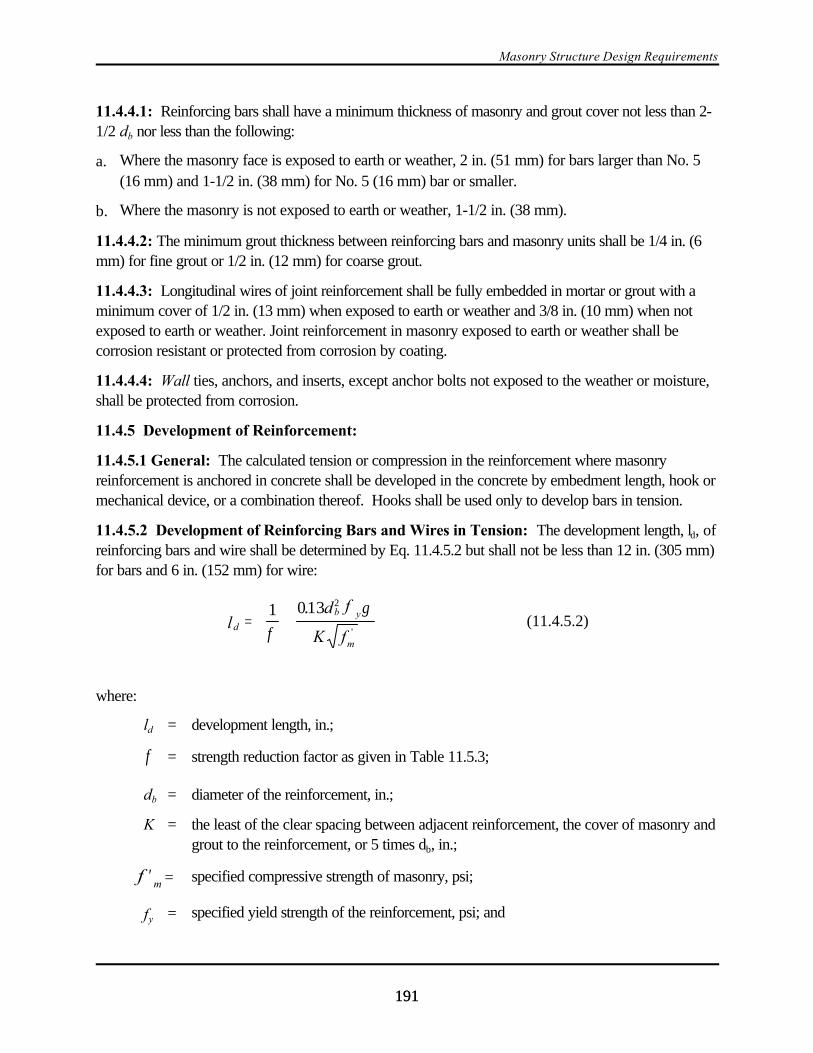
Masonry Structure Design Requirements
191191
11.4.4.1: Reinforcing bars shall have a minimum thickness of masonry and grout cover not less than 2-1/2 db nor less than the following:
a. Where the masonry face is exposed to earth or weather, 2 in. (51 mm) for bars larger than No. 5(16 mm) and 1-1/2 in. (38 mm) for No. 5 (16 mm) bar or smaller.
b. Where the masonry is not exposed to earth or weather, 1-1/2 in. (38 mm).
11.4.4.2: The minimum grout thickness between reinforcing bars and masonry units shall be 1/4 in. (6mm) for fine grout or 1/2 in. (12 mm) for coarse grout.
11.4.4.3: Longitudinal wires of joint reinforcement shall be fully embedded in mortar or grout with aminimum cover of 1/2 in. (13 mm) when exposed to earth or weather and 3/8 in. (10 mm) when notexposed to earth or weather. Joint reinforcement in masonry exposed to earth or weather shall becorrosion resistant or protected from corrosion by coating.
11.4.4.4: Wall ties, anchors, and inserts, except anchor bolts not exposed to the weather or moisture,shall be protected from corrosion.
11.4.5 Development of Reinforcement:
11.4.5.1 General: The calculated tension or compression in the reinforcement where masonryreinforcement is anchored in concrete shall be developed in the concrete by embedment length, hook ormechanical device, or a combination thereof. Hooks shall be used only to develop bars in tension.
11.4.5.2 Development of Reinforcing Bars and Wires in Tension: The development length, ld, ofreinforcing bars and wire shall be determined by Eq. 11.4.5.2 but shall not be less than 12 in. (305 mm)for bars and 6 in. (152 mm) for wire:
(11.4.5.2)d
b y
m
ld f
K f=
1 013 2
φγ.
'
where:
ld = development length, in.;
= strength reduction factor as given in Table 11.5.3;φ
db = diameter of the reinforcement, in.;
K = the least of the clear spacing between adjacent reinforcement, the cover of masonry andgrout to the reinforcement, or 5 times db, in.;
= specified compressive strength of masonry, psi;mf ′
fy = specified yield strength of the reinforcement, psi; and
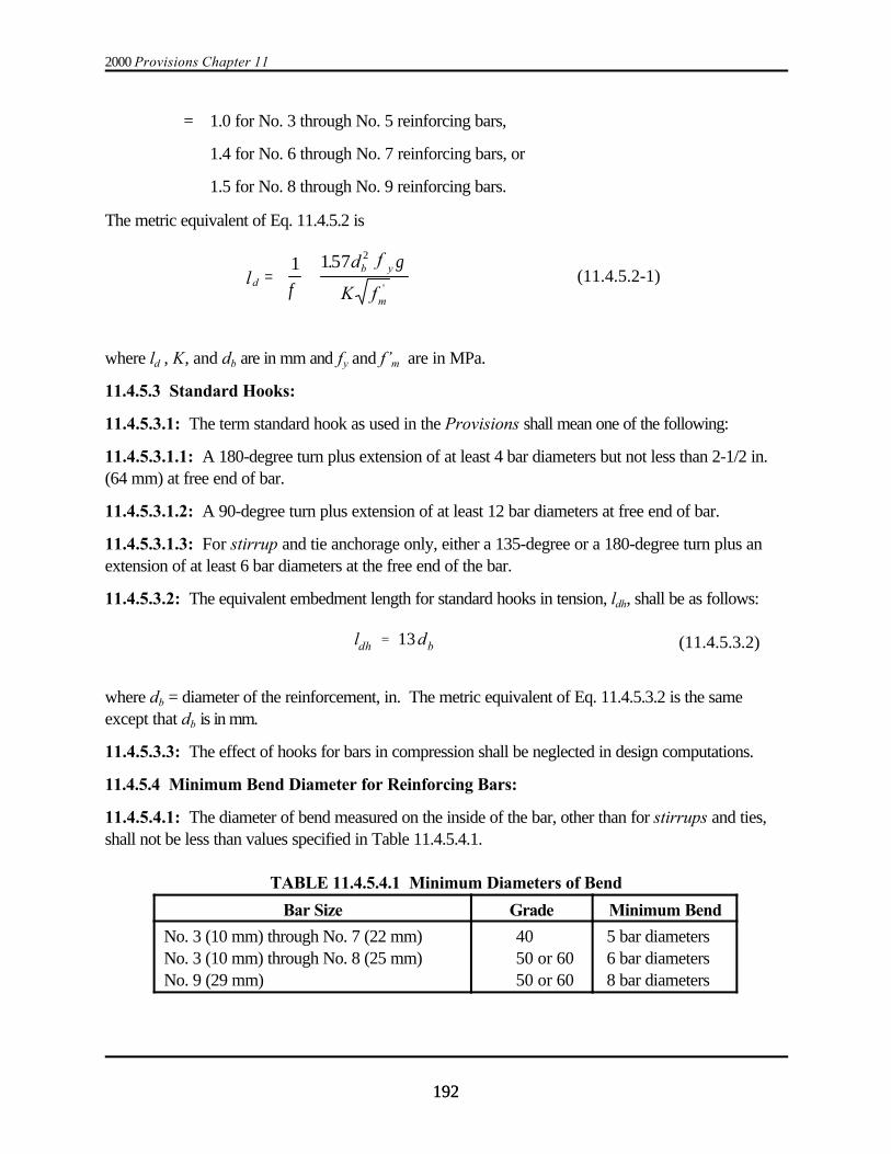
2000 Provisions Chapter 11
192192
ldh ' 13db (11.4.5.3.2)
= 1.0 for No. 3 through No. 5 reinforcing bars,
1.4 for No. 6 through No. 7 reinforcing bars, or
1.5 for No. 8 through No. 9 reinforcing bars.
The metric equivalent of Eq. 11.4.5.2 is
(11.4.5.2-1)db y
m
ld f
K f=
1 157 2
φγ.
'
where ld , K, and db are in mm and fy and f’m are in MPa.
11.4.5.3 Standard Hooks:
11.4.5.3.1: The term standard hook as used in the Provisions shall mean one of the following:
11.4.5.3.1.1: A 180-degree turn plus extension of at least 4 bar diameters but not less than 2-1/2 in.(64 mm) at free end of bar.
11.4.5.3.1.2: A 90-degree turn plus extension of at least 12 bar diameters at free end of bar.
11.4.5.3.1.3: For stirrup and tie anchorage only, either a 135-degree or a 180-degree turn plus anextension of at least 6 bar diameters at the free end of the bar.
11.4.5.3.2: The equivalent embedment length for standard hooks in tension, ldh, shall be as follows:
where db = diameter of the reinforcement, in. The metric equivalent of Eq. 11.4.5.3.2 is the sameexcept that db is in mm.
11.4.5.3.3: The effect of hooks for bars in compression shall be neglected in design computations.
11.4.5.4 Minimum Bend Diameter for Reinforcing Bars:
11.4.5.4.1: The diameter of bend measured on the inside of the bar, other than for stirrups and ties,shall not be less than values specified in Table 11.4.5.4.1.
TABLE 11.4.5.4.1 Minimum Diameters of Bend
Bar Size Grade Minimum Bend
No. 3 (10 mm) through No. 7 (22 mm)No. 3 (10 mm) through No. 8 (25 mm)No. 9 (29 mm)
4050 or 6050 or 60
5 bar diameters 6 bar diameters 8 bar diameters

Masonry Structure Design Requirements
193193
11.4.5.5 Development of Shear Reinforcement:
11.4.5.5.1: Shear reinforcement shall extend the depth of the member less cover distances.
11.4.5.5.2: The ends of single leg or U-stirrups shall be anchored by one of the following means:
a. A standard hook plus an effective embedment of 0.5 times the development length, ld. Theeffective embedment of a stirrup leg shall be taken as the distance between the mid-depth of themember and the start of the hook (point of tangency).
b. For No. 5 (16 mm) bar and D31 wire and smaller, bending around longitudinal reinforcementthrough at least 135 degrees plus an embedment of ld/3 . The ld/3 embedment of a stirrup leg shallbe taken as the distance between mid-depth of the member and the start of the hook (point oftangency).
c. Between the anchored ends, each bend in the continuous portion of a transverse U-stirrup shallenclose a longitudinal bar.
11.4.5.5.3: Except at wall intersections, the end of a reinforcing bar needed to satisfy shear strengthrequirements in accordance with Sec. 11.7.3.3 shall be bent around the edge vertical reinforcing barwith a 180-degree hook. At wall intersections, reinforcing bars used as shear reinforcement shall bebent around the edge vertical bar with a 90-degree standard hook and shall extend horizontally into theintersecting wall.
11.4.5.6 Splices of Reinforcement: Lap splices, welded splices, or mechanical connections shall bein accordance with the provisions of this section.
11.4.5.6.1 Lap Splices: Lap splices shall not be used in plastic hinge zones. The length of the plastichinge zone shall be taken as at least 0.15 times the distance between the point of zero moment and thepoint of maximum moment.
11.4.5.6.1.1: The minimum length of lap, lld, for bars in tension or compression shall be equal to thedevelopment length, ld, as determined by Eq. 11.4.5.2 but shall not be less than 12 in. (305 mm) forbars and 6 in (152 mm) for wire.
11.4.5.6.1.2: Bars spliced by non-contact lap splices shall not be spaced transversely farther apartthan one-fifth the required length of lap or more than 8 in. (203 mm).
11.4.5.6.2 Welded Splices: A welded splice shall be capable of developing in tension 125 percent ofthe specified yield strength, fy, of the bar. Welded splices shall only be permitted for ASTM A706 steelreinforcement. Welded splices shall not be permitted in plastic hinge zones of intermediate or specialreinforced walls or special moment frames of masonry.
11.4.5.6.3 Mechanical Splices: Mechanical splices shall be classified as Type 1 or Type 2 accordingto Sec. 21.2.6.1 of ACI 318.

2000 Provisions Chapter 11
194194
Type 1 mechanical splices shall not be used within a plastic hinge zone or within a beam-column joint ofintermediate or special reinforced masonry shear walls or special moment frames. Type 2 mechanicalsplices shall be permitted in any location within a member.
11.5 STRENGTH AND DEFORMATION REQUIREMENTS:
11.5.1 General: Masonry structures and masonry members shall be designed to have strength at allsections at least equal to the required strength calculated for the factored loads in such combinationsas are stipulated in these provisions.
11.5.2 Required Strength: The required strength shall be determined in accordance with Chapters 5 and 6.
11.5.3 Design Strength: Design strength provided by a member and its connections to othermembers and its cross sections in terms of flexure, axial load, and shear shall be taken as the nominalstrength multiplied by a strength reduction factor, N, as specified in Table 11.5.3.
TABLE 11.5.3 Strength Reduction Factor NN
Axial load, flexure, andcombinations of axial loadand flexure
Reinforced masonryPlain masonry
N = 0.85N = 0.60
Shear Reinforced masonry N = 0.80
Shear Plain masonry N = 0.80
Reinforcement development length and splices N = 0.80
Anchor bolt strength as governed by steel N = 0.90
Anchor bolt strength as governed by masonry N = 0.50
Bearing N = 0.60
11.5.4 Deformation Requirements:
11.5.4.1: Masonry structures shall be designed so the design story drift, ), does not exceed theallowable story drift, )a, obtained from Table 5.2.8.
11.5.4.1.1: Cantilever shear walls shall be proportioned such that the maximum displacement, *max, atLevel n does not exceed 0.01hn.
11.5.4.2: Deflection calculations for plain masonry members shall be based on uncracked sectionproperties.
11.5.4.3: Deflection calculations for reinforced masonry members shall be based on an effectivemoment of inertia in accordance with the following:
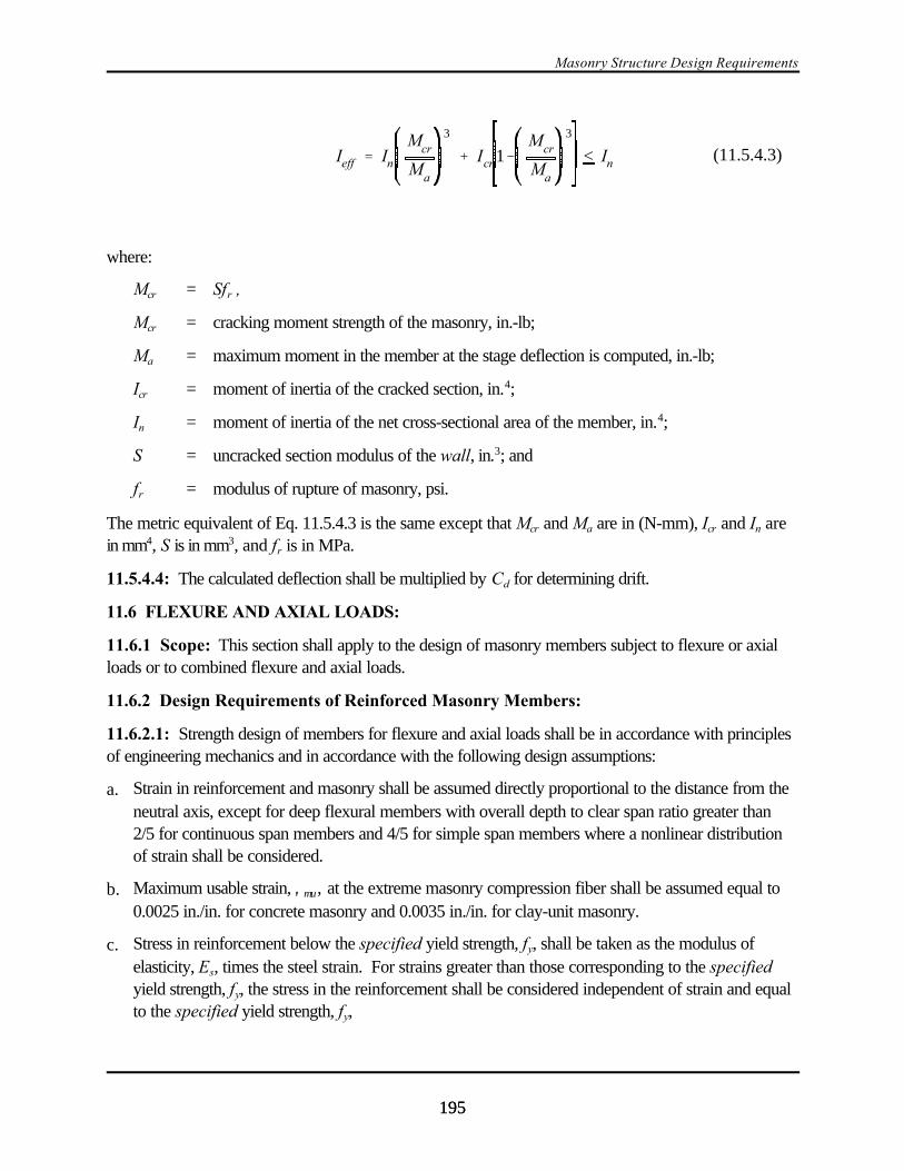
Masonry Structure Design Requirements
195195
Ieff ' In
Mcr
Ma
3
% Icr 1&Mcr
Ma
3
< In (11.5.4.3)
where:
Mcr = Sfr ,
Mcr = cracking moment strength of the masonry, in.-lb;
Ma = maximum moment in the member at the stage deflection is computed, in.-lb;
Icr = moment of inertia of the cracked section, in.4;
In = moment of inertia of the net cross-sectional area of the member, in.4;
S = uncracked section modulus of the wall, in.3; and
fr = modulus of rupture of masonry, psi.
The metric equivalent of Eq. 11.5.4.3 is the same except that Mcr and Ma are in (N-mm), Icr and In arein mm4, S is in mm3, and fr is in MPa.
11.5.4.4: The calculated deflection shall be multiplied by Cd for determining drift.
11.6 FLEXURE AND AXIAL LOADS:
11.6.1 Scope: This section shall apply to the design of masonry members subject to flexure or axialloads or to combined flexure and axial loads.
11.6.2 Design Requirements of Reinforced Masonry Members:
11.6.2.1: Strength design of members for flexure and axial loads shall be in accordance with principlesof engineering mechanics and in accordance with the following design assumptions:
a. Strain in reinforcement and masonry shall be assumed directly proportional to the distance from theneutral axis, except for deep flexural members with overall depth to clear span ratio greater than2/5 for continuous span members and 4/5 for simple span members where a nonlinear distributionof strain shall be considered.
b. Maximum usable strain, ,µυ, at the extreme masonry compression fiber shall be assumed equal to0.0025 in./in. for concrete masonry and 0.0035 in./in. for clay-unit masonry.
c. Stress in reinforcement below the specified yield strength, fy, shall be taken as the modulus ofelasticity, Es, times the steel strain. For strains greater than those corresponding to the specifiedyield strength, fy, the stress in the reinforcement shall be considered independent of strain and equalto the specified yield strength, fy,
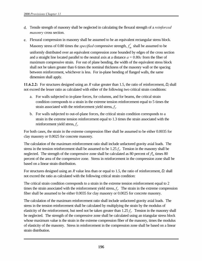
2000 Provisions Chapter 11
196196
d. Tensile strength of masonry shall be neglected in calculating the flexural strength of a reinforcedmasonry cross section.
e. Flexural compression in masonry shall be assumed to be an equivalent rectangular stress block.
Masonry stress of 0.80 times the specified compressive strength, shall be assumed to bef )muniformly distributed over an equivalent compression zone bounded by edges of the cross sectionand a straight line located parallel to the neutral axis at a distance a = 0.80c from the fiber ofmaximum compressive strain. For out of plane bending, the width of the equivalent stress blockshall not be taken greater than 6 times the nominal thickness of the masonry wall or the spacingbetween reinforcement, whichever is less. For in-plane bending of flanged walls, the samedimension shall apply.
11.6.2.2: For structures designed using an R value greater than 1.5, the ratio of reinforcement, D, shallnot exceed the lesser ratio as calculated with either of the following two critical strain conditions:
a. For walls subjected to in-plane forces, for columns, and for beams, the critical straincondition corresponds to a strain in the extreme tension reinforcement equal to 5 times thestrain associated with the reinforcement yield stress, fy.
b. For walls subjected to out-of-plane forces, the critical strain condition corresponds to astrain in the extreme tension reinforcement equal to 1.3 times the strain associated with thereinforcement yield stress, fy.
For both cases, the strain in the extreme compression fiber shall be assumed to be either 0.0035 forclay masonry or 0.0025 for concrete masonry.
The calculation of the maximum reinforcement ratio shall include unfactored gravity axial loads. Thestress in the tension reinforcement shall be assumed to be 1.25 fy. Tension in the masonry shall beneglected. The strength of the compressive zone shall be calculated as 80 percent of f!m times 80percent of the area of the compressive zone. Stress in reinforcement in the compression zone shall bebased on a linear strain distribution.
For structures designed using an R value less than or equal to 1.5, the ratio of reinforcement, D, shallnot exceed the ratio as calculated with the following critical strain condition:
The critical strain condition corresponds to a strain in the extreme tension reinforcement equal to 2times the strain associated with the reinforcement yield stress, fy. The strain in the extreme compressionfiber shall be assumed to be either 0.0035 for clay masonry or 0.0025 for concrete masonry.
The calculation of the maximum reinforcement ratio shall include unfactored gravity axial loads. Thestress in the tension reinforcement shall be calculated by multiplying the strain by the modulus ofelasticity of the reinforcement, but need not be taken greater than 1.25 fy. Tension in the masonry shallbe neglected. The strength of the compressive zone shall be calculated using an triangular stress blockwhose maximum value is the strain in the extreme compression fiber of the masonry, times the modulusof elasticity of the masonry. Stress in reinforcement in the compression zone shall be based on a linearstrain distribution.
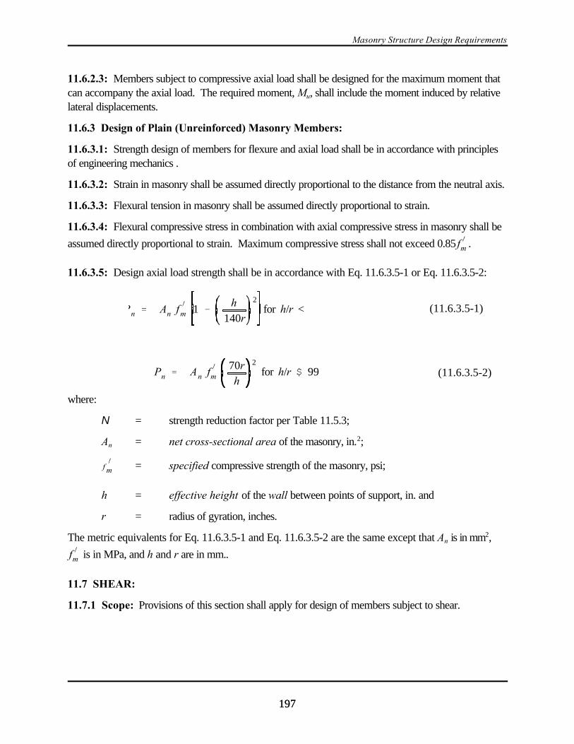
Masonry Structure Design Requirements
197197
Pn ' An f)
m 1 &h
140r
2for h/r < (11.6.3.5-1)
Pn ' An f)
m70r
h
2for h/r $ 99 (11.6.3.5-2)
11.6.2.3: Members subject to compressive axial load shall be designed for the maximum moment thatcan accompany the axial load. The required moment, Mu, shall include the moment induced by relativelateral displacements.
11.6.3 Design of Plain (Unreinforced) Masonry Members:
11.6.3.1: Strength design of members for flexure and axial load shall be in accordance with principlesof engineering mechanics .
11.6.3.2: Strain in masonry shall be assumed directly proportional to the distance from the neutral axis.
11.6.3.3: Flexural tension in masonry shall be assumed directly proportional to strain.
11.6.3.4: Flexural compressive stress in combination with axial compressive stress in masonry shall be
assumed directly proportional to strain. Maximum compressive stress shall not exceed 0.85 .f )m
11.6.3.5: Design axial load strength shall be in accordance with Eq. 11.6.3.5-1 or Eq. 11.6.3.5-2:
where:
N = strength reduction factor per Table 11.5.3;
An = net cross-sectional area of the masonry, in.2;
= specified compressive strength of the masonry, psi;f)
m
h = effective height of the wall between points of support, in. and
r = radius of gyration, inches.
The metric equivalents for Eq. 11.6.3.5-1 and Eq. 11.6.3.5-2 are the same except that An is in mm2,
is in MPa, and h and r are in mm..f )m
11.7 SHEAR:
11.7.1 Scope: Provisions of this section shall apply for design of members subject to shear.
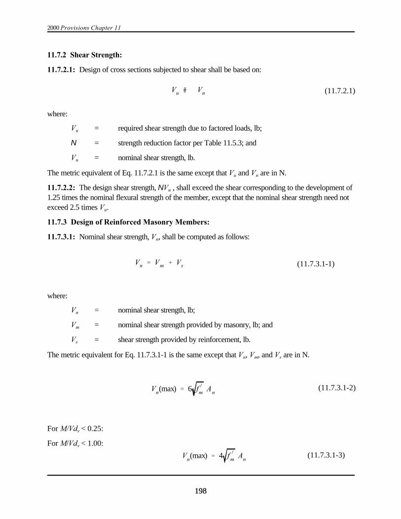
2000 Provisions Chapter 11
198198
Vu # Vn (11.7.2.1)
Vn ' Vm % Vs (11.7.3.1-1)
Vn(max) ' 6 f )m An(11.7.3.1-2)
Vn(max) ' 4 f )
m An(11.7.3.1-3)
11.7.2 Shear Strength:
11.7.2.1: Design of cross sections subjected to shear shall be based on:
where:
Vu = required shear strength due to factored loads, lb;
N = strength reduction factor per Table 11.5.3; and
Vn = nominal shear strength, lb.
The metric equivalent of Eq. 11.7.2.1 is the same except that Vu and Vn are in N.
11.7.2.2: The design shear strength, NVn , shall exceed the shear corresponding to the development of1.25 times the nominal flexural strength of the member, except that the nominal shear strength need notexceed 2.5 times Vu.
11.7.3 Design of Reinforced Masonry Members:
11.7.3.1: Nominal shear strength, Vn, shall be computed as follows:
where:
Vn = nominal shear strength, lb;
Vm = nominal shear strength provided by masonry, lb; and
Vs = shear strength provided by reinforcement, lb.
The metric equivalent for Eq. 11.7.3.1-1 is the same except that Vn, Vm, and Vs are in N.
For M/Vdv < 0.25:
For M/Vdv < 1.00:
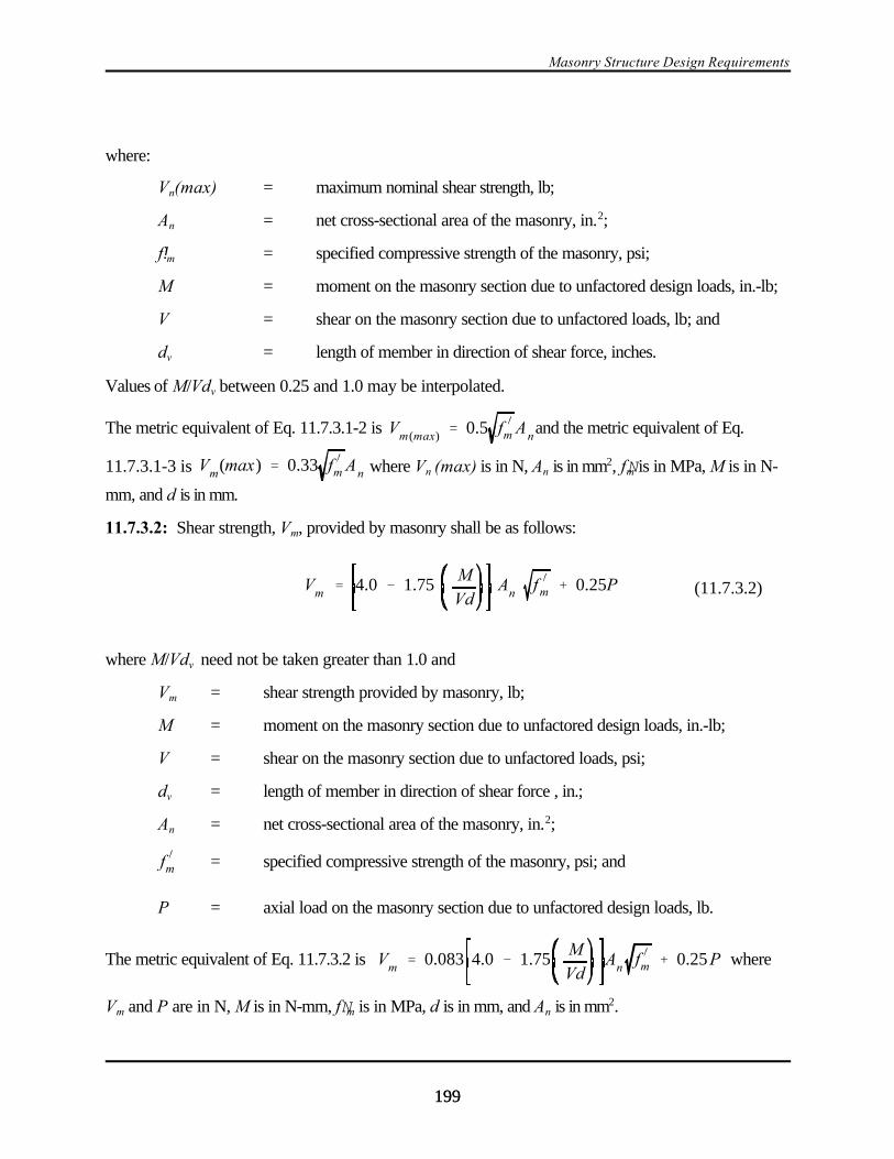
Masonry Structure Design Requirements
199199
Vm ' 4.0 & 1.75M
VdAn f )
m % 0.25P (11.7.3.2)
where:
Vn(max) = maximum nominal shear strength, lb;
An = net cross-sectional area of the masonry, in.2;
f!m = specified compressive strength of the masonry, psi;
M = moment on the masonry section due to unfactored design loads, in.-lb;
V = shear on the masonry section due to unfactored loads, lb; and
dv = length of member in direction of shear force, inches.
Values of M/Vdv between 0.25 and 1.0 may be interpolated.
The metric equivalent of Eq. 11.7.3.1-2 is and the metric equivalent of Eq.Vm(max) ' 0.5 f )
m An
11.7.3.1-3 is where Vn (max) is in N, An is in mm2, fNm is in MPa, M is in N-Vm(max) ' 0.33 f )m An
mm, and d is in mm.
11.7.3.2: Shear strength, Vm, provided by masonry shall be as follows:
where M/Vdv need not be taken greater than 1.0 and
Vm = shear strength provided by masonry, lb;
M = moment on the masonry section due to unfactored design loads, in.-lb;
V = shear on the masonry section due to unfactored loads, psi;
dv = length of member in direction of shear force , in.;
An = net cross-sectional area of the masonry, in.2;
= specified compressive strength of the masonry, psi; andf )m
P = axial load on the masonry section due to unfactored design loads, lb.
The metric equivalent of Eq. 11.7.3.2 is whereVm ' 0.083 4.0 & 1.75M
VdAn f )m % 0.25P
Vm and P are in N, M is in N-mm, fNm is in MPa, d is in mm, and An is in mm2.

2000 Provisions Chapter 11
200200
Vs ' 0.5Av
sfy dv (11.7.3.3)
11.7.3.3: Nominal shear strength, Vs, provided by reinforcement shall be as follows:
where:
Av = area of shear reinforcement, in.2 (mm2);
dv = length of member in direction of shear force, in. (mm);
s = spacing of shear reinforcement, in. (mm); and
fy = specified yield strength of the reinforcement or the anchor bolt as applicable, psi(MPa).
The metric equivalent of Eq. 11.7.3.3 is the same.
11.7.4 Design of Plain (Unreinforced) Masonry Members:
11.7.4.1: Nominal shear strength, Vn, shall be the least of the following:
a. 1.50 An, lb (the metric equivalent is 0.375 An, where is in MPa and An is in mm2);f )m f )m f )m
b. 120An, lb (the metric equivalent is 0.83An, N, where An is in mm2);
c. 37 An + 0.3 Nv for running bond masonry not grouted solid, lb (the metric equivalent is 0.26An
+ 0.3Nv where An is in mm2 and Nv is in N);
37 An + 0.3 Nv for stack bond masonry with open end units grouted solid, lb (the metricequivalent is 0.26An + 0.3Nv when An is in mm2 and Nv is in N);
60 An + 0.3 Nv for running bond masonry grouted solid, lb (the metric equivalent is 0.414An +0.3Nv when An is in mm2 and Nv is in N); and
15 An for stack bond masonry with other than open end units grouted solid, lb (the metricequivalent is 0.103An when An is in mm2
where:
= specified compressive strength of the masonry, psi;f)
m
An = net cross-sectional area of the masonry, in.2; and
Nv = force acting normal to shear surface, lb.
11.8 SPECIAL REQUIREMENTS FOR BEAMS:

Masonry Structure Design Requirements
201201
11.8.1: The spacing between lateral supports shall be determined by the requirements for out of-planeloading but shall not exceed 32 times the least width of beam.
11.8.2: The effects of lateral eccentricity of load shall be taken into account in determining spacing oflateral supports.
11.8.3: The minimum positive reinforcement ratio ρ in a beam shall not be less than 120/fy (the metricequivalent is 0.83/fy where fy is in MPa) except that this minimum positive steel reinforcement ratio neednot be satisfied if the area of reinforcement provided is one third greater than that required by analysisfor gravity loads and the Seismic Design Category is A, B, or C.
Where a concrete floor provides a flange and where the beam web is in tension, the ratio, D, shall becomputed using the web width.
11.8.4 Deep Flexural Members:
11.8.4.1: Flexural members with overall depth to clear span ratios greater than 2/5 for continuousspans or 4/5 for simple spans shall be designed as deep flexural members taking into account nonlineardistribution of strain and lateral buckling.
11.8.4.2: Minimum flexural tension reinforcement shall conform to Sec. 11.8.3.
11.8.4.3: Uniformly distributed horizontal and vertical reinforcement shall be provided throughout thelength and depth of deep flexural members such that the reinforcement ratios in both directions are atleast 0.001. Distributed flexural reinforcement is to be included in the determination of the actualreinforcement ratios.
11.9 SPECIAL REQUIREMENTS FOR COLUMNS:
11.9.1: Area of longitudinal reinforcement for columns shall be not less than 0.005 or more than 0.04times cross-sectional area of the column.
11.9.2: There shall be a minimum of four longitudinal bars in columns.
11.9.3: Lateral ties shall be provided to resist shear and shall comply with the following:
a. Lateral ties shall be at least 1/4 in. (6 mm) in diameter.
b. Vertical spacing of lateral ties shall not exceed 16 longitudinal bar diameters, 48 lateral tiediameters, nor the least cross sectional dimension of the column.
c. Lateral ties shall be arranged such that every corner and alternate longitudinal bar shall have lateralsupport provided by the corner of a lateral tie with an included angle of not more than 135 degreesand no bar shall be farther than 6 in. (152 mm) clear on each side along the lateral tie from such alaterally supported bar. Lateral ties shall be placed in either a mortar joint or grout. Wherelongitudinal bars are located around the perimeter of a circle, a complete circular lateral tie ispermitted. Minimum lap length for circular ties shall be 84 tie diameters.
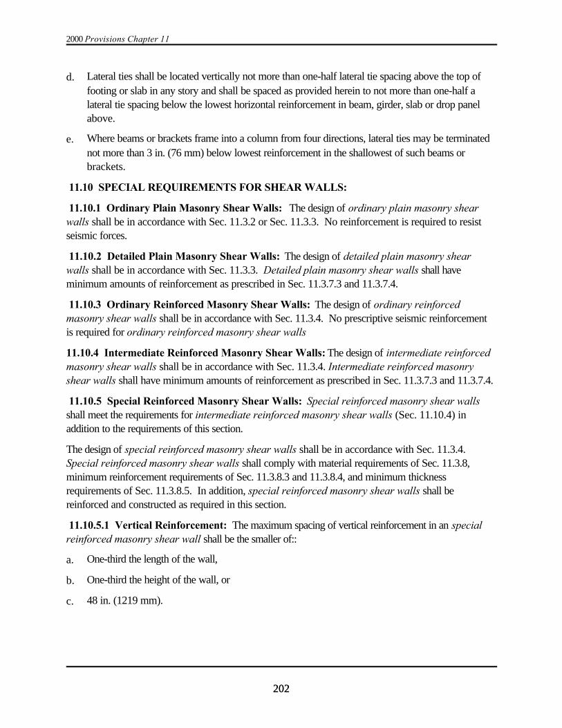
2000 Provisions Chapter 11
202202
d. Lateral ties shall be located vertically not more than one-half lateral tie spacing above the top offooting or slab in any story and shall be spaced as provided herein to not more than one-half alateral tie spacing below the lowest horizontal reinforcement in beam, girder, slab or drop panelabove.
e. Where beams or brackets frame into a column from four directions, lateral ties may be terminatednot more than 3 in. (76 mm) below lowest reinforcement in the shallowest of such beams orbrackets.
11.10 SPECIAL REQUIREMENTS FOR SHEAR WALLS:
11.10.1 Ordinary Plain Masonry Shear Walls: The design of ordinary plain masonry shearwalls shall be in accordance with Sec. 11.3.2 or Sec. 11.3.3. No reinforcement is required to resistseismic forces.
11.10.2 Detailed Plain Masonry Shear Walls: The design of detailed plain masonry shearwalls shall be in accordance with Sec. 11.3.3. Detailed plain masonry shear walls shall haveminimum amounts of reinforcement as prescribed in Sec. 11.3.7.3 and 11.3.7.4.
11.10.3 Ordinary Reinforced Masonry Shear Walls: The design of ordinary reinforcedmasonry shear walls shall be in accordance with Sec. 11.3.4. No prescriptive seismic reinforcementis required for ordinary reinforced masonry shear walls
11.10.4 Intermediate Reinforced Masonry Shear Walls: The design of intermediate reinforcedmasonry shear walls shall be in accordance with Sec. 11.3.4. Intermediate reinforced masonryshear walls shall have minimum amounts of reinforcement as prescribed in Sec. 11.3.7.3 and 11.3.7.4.
11.10.5 Special Reinforced Masonry Shear Walls: Special reinforced masonry shear wallsshall meet the requirements for intermediate reinforced masonry shear walls (Sec. 11.10.4) inaddition to the requirements of this section.
The design of special reinforced masonry shear walls shall be in accordance with Sec. 11.3.4. Special reinforced masonry shear walls shall comply with material requirements of Sec. 11.3.8,minimum reinforcement requirements of Sec. 11.3.8.3 and 11.3.8.4, and minimum thicknessrequirements of Sec. 11.3.8.5. In addition, special reinforced masonry shear walls shall bereinforced and constructed as required in this section.
11.10.5.1 Vertical Reinforcement: The maximum spacing of vertical reinforcement in an specialreinforced masonry shear wall shall be the smaller of::
a. One-third the length of the wall,
b. One-third the height of the wall, or
c. 48 in. (1219 mm).
Masonry Structure Design Requirements
203203
11.10.5.2 Horizontal Reinforcement: Reinforcement required to resist in-plane shear in a specialreinforced masonry shear wall shall be placed horizontally, shall be uniformly distributed, and shall beembedded in grout. The maximum spacing of horizontal reinforcement shall be the smaller of:
a. One-third the length of the wall,
b. One-third the height of the wall,
c. 48 in. (1219 mm), or
d. 24 in. (610 mm) for stack bond masonry.
11.10.5.3 Shear Keys: The surface of concrete upon which a special reinforced masonry shearwall is constructed shall have a minimum surface roughness of 1/8 in. (3.0 mm). Keys with thefollowing minimum requirements shall be placed at the base of special reinforced masonry shearwalls when the calculated strain in vertical reinforcement exceeds the yield strain under loadcombinations that include seismic forces based on a R factor equal to 1.5:
a. The width of the keys shall be at least equal to the width of the grout space
b. The depth of the keys shall be at least 1.5 in. (40 mm),
c. The length of the key shall be at least 6 in. (152 mm),
d. The spacing between keys shall be at least equal to the length of the key,
e. The cumulative length of all keys shall be at least 20 percent of the length of the shear wall,
f. A minimum of one key shall be placed within 16 in. (406 mm) of each end of a shear wall, and
g. Each key and the grout space above each key in the first course of masonry shall be grouted solid.
11.10.6: Flanged Shear Walls:
11.10.6.1: Wall intersections shall be considered effective in transferring shear when eitherconditions (a) or (b) and condition (c) as noted below are met:
a. The face shells of hollow masonry units are removed and the intersection is fully grouted.
b. Solid units are laid in running bond and 50 percent of the masonry units at the intersection areinterlocked.
c. Reinforcement from one intersecting wall continues past the intersection a distance not less than 40bar diameters or 24 in. (600 mm).
11.10.6.2: The width of flange considered effective in compression on each side of the web shall betaken equal to 6 times the thickness of the web or shall be equal to the actual flange on either side of theweb wall, whichever is less.
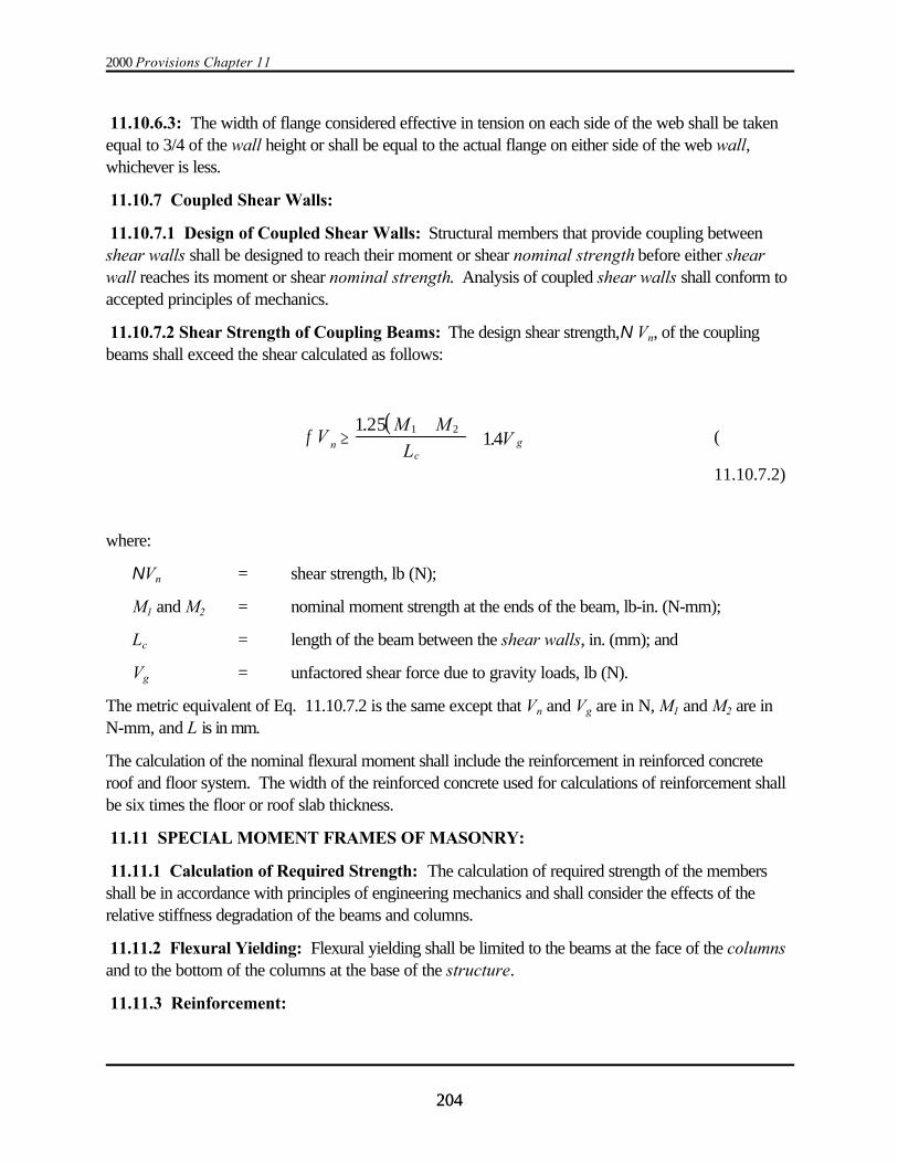
2000 Provisions Chapter 11
204204
11.10.6.3: The width of flange considered effective in tension on each side of the web shall be takenequal to 3/4 of the wall height or shall be equal to the actual flange on either side of the web wall,whichever is less.
11.10.7 Coupled Shear Walls:
11.10.7.1 Design of Coupled Shear Walls: Structural members that provide coupling betweenshear walls shall be designed to reach their moment or shear nominal strength before either shearwall reaches its moment or shear nominal strength. Analysis of coupled shear walls shall conform toaccepted principles of mechanics.
11.10.7.2 Shear Strength of Coupling Beams: The design shear strength,N Vn, of the couplingbeams shall exceed the shear calculated as follows:
(( )
nc
gVM M
LVφ ≥
++
1 2514
1 2..
11.10.7.2)
where:
NVn = shear strength, lb (N);
M1 and M2 = nominal moment strength at the ends of the beam, lb-in. (N-mm);
Lc = length of the beam between the shear walls, in. (mm); and
Vg = unfactored shear force due to gravity loads, lb (N).
The metric equivalent of Eq. 11.10.7.2 is the same except that Vn and Vg are in N, M1 and M2 are inN-mm, and L is in mm.
The calculation of the nominal flexural moment shall include the reinforcement in reinforced concreteroof and floor system. The width of the reinforced concrete used for calculations of reinforcement shallbe six times the floor or roof slab thickness.
11.11 SPECIAL MOMENT FRAMES OF MASONRY:
11.11.1 Calculation of Required Strength: The calculation of required strength of the membersshall be in accordance with principles of engineering mechanics and shall consider the effects of therelative stiffness degradation of the beams and columns.
11.11.2 Flexural Yielding: Flexural yielding shall be limited to the beams at the face of the columnsand to the bottom of the columns at the base of the structure.
11.11.3 Reinforcement:
Masonry Structure Design Requirements
205205
11.11.3.1: The nominal moment strength at any section along a member shall not be less than one-halfof the higher moment strength provided at the two ends of the member.
11.11.3.2: Lap splices are permitted only within the center half of the member length.
11.11.3.3: Welded splices and mechanical connections may be used for splicing the reinforcement atany section provided not more than alternate longitudinal bars are spliced at a section and the distancebetween splices on alternate bars is at least 24 in. (610 mm) along the longitudinal axis.
11.11.3.4: Reinforcement shall have a specified yield strength of 60,000 psi (414 MPa). The actualyield strength shall not exceed 1.5 times the specified yield strength.
11.11.4 Wall Frame Beams:
11.11.4.1: Factored axial compression force on the beam shall not exceed 0.10 times the net cross-
sectional area of the beam, An , times the specified compressive strength, .f )m
11.11.4.2: Beams interconnecting vertical elements of the lateral-load-resisting system shall be limitedto a reinforcement ratio of 0.15f!m/fy or that determined in accordance with Sec. 11.6.2.2. Allreinforcement in the beam and adjacent to the beam in a reinforced concrete roof or floor system shallbe used to calculate the reinforcement ratio.
11.11.4.3: Clear span for the beam shall not be less than 4 times its depth.
11.11.4.4: Nominal depth of the beam shall not be less than 4 units or 32 in. (813 mm), whichever isgreater. The nominal depth to nominal width ratio shall not exceed 4.
11.11.4.5: Nominal width of the beams shall equal or exceed all of the following criteria:
a. 8 in. (203 mm),
b. Width required by Sec. 11.8.1, and
c. 1/26 of the clear span between column faces.
11.11.4.6: Longitudinal Reinforcement:
11.11.4.6.1: Longitudinal reinforcement shall not be spaced more than 8 in. (203 mm) on center.
11.11.4.6.2: Longitudinal reinforcement shall be uniformly distributed along the depth of the beam.
11.11.4.6.3: In lieu of the limitations of Sec. 11.8.3, the minimum reinforcement ratio shall be 130/fy
(the metric equivalent is 0.90/fy where fy is in MPa).
11.11.4.6.4: At any section of a beam, each masonry unit through the beam depth shall containlongitudinal reinforcement.

2000 Provisions Chapter 11
206206
11.11.4.7 Transverse Reinforcement:
11.11.4.7.1: Transverse reinforcement shall be hooked around top and bottom longitudinal bars andshall be terminated with a standard 180-degree hook.
11.11.4.7.2: Within an end region extending one beam depth from wall frame column faces and atany region at which beam plastic hinges may form during seismic or wind loading, maximum spacing oftransverse reinforcement shall not exceed one-fourth the nominal depth of the beam.
11.11.4.7.3: The maximum spacing of transverse reinforcement shall not exceed one-half the nominaldepth of the beam or that required for shear strength.
11.11.4.7.4: Minimum transverse reinforcement ratio shall be 0.0015.
11.11.4.7.5: The first transverse bar shall not be more than 4 in. (102 mm) from the face of the pier.
11.11.5 Wall Frame Columns:
11.11.5.1: Factored axial compression force on the wall frame column shall not exceed 0.15 times
the net cross-sectional area of the column, An, times the specified compressive strength, . Thef )mcompressive stress shall also be limited by the maximum reinforcement ratio.
11.11.5.2: Nominal dimension of the column parallel to the plane of the wall frame shall not be lessthan two full units or 32 in. (810 mm), whichever is greater.
11.11.5.3: Nominal dimension of the column perpendicular to the plane of the wall frame shall notbe less than 8 in. (203 mm) or 1/14 of the clear height between beam faces.
11.11.5.4: The clear height-to-depth ratio of column members shall not exceed 5.
11.11.5.5 Longitudinal Reinforcement:
11.11.5.5.1: A minimum of 4 longitudinal bars shall be provided at all sections of every wall framecolumn member.
11.11.5.5.2: The flexural reinforcement shall be uniformly distributed across the member depth.
11.11.5.5.3: The nominal moment strength at any section along a member shall be not less than 1.6times the cracking moment strength and the minimum reinforcement ratio shall be 130/fy (the metricequivalent is 0.90/fy where fy is in MPa).
11.11.5.5.4: Vertical reinforcement in wall-frame columns shall be limited to a maximumreinforcement ratio equal to the lesser of 0.15f!m / fy or that determined in accordance with Sec.11.6.2.2.
11.11.5.6 Transverse Reinforcement:
11.11.5.6.1: Transverse reinforcement shall be hooked around the extreme longitudinal bars and shallbe terminated with a standard 180-degree hook.
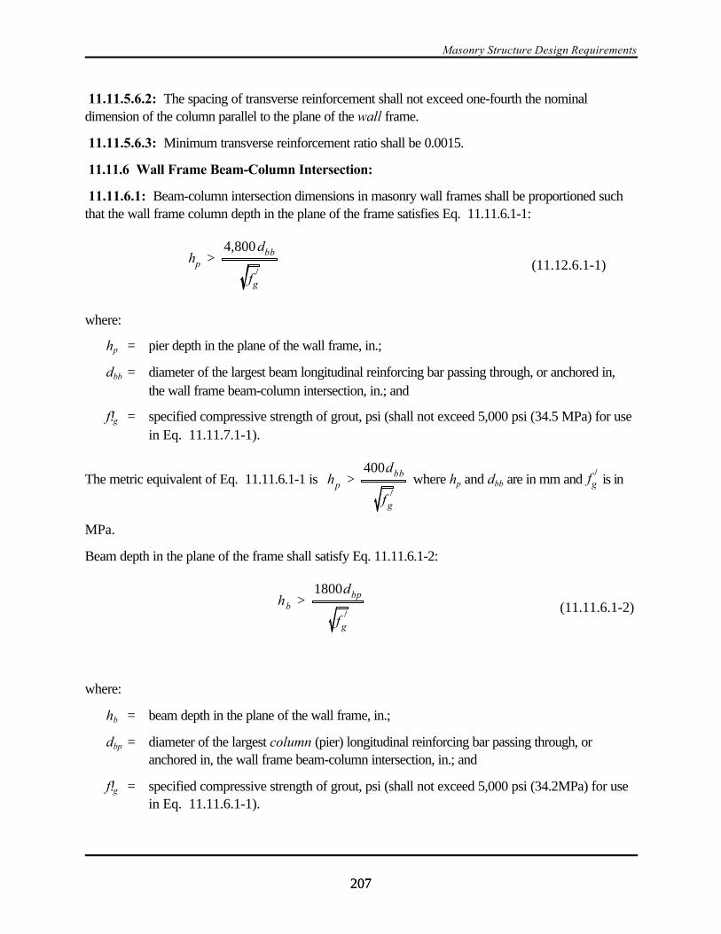
Masonry Structure Design Requirements
207207
hp >4,800dbb
f)
g
(11.12.6.1-1)
hb >1800dbp
f)
g
(11.11.6.1-2)
11.11.5.6.2: The spacing of transverse reinforcement shall not exceed one-fourth the nominaldimension of the column parallel to the plane of the wall frame.
11.11.5.6.3: Minimum transverse reinforcement ratio shall be 0.0015.
11.11.6 Wall Frame Beam-Column Intersection:
11.11.6.1: Beam-column intersection dimensions in masonry wall frames shall be proportioned suchthat the wall frame column depth in the plane of the frame satisfies Eq. 11.11.6.1-1:
where:
hp = pier depth in the plane of the wall frame, in.;
dbb = diameter of the largest beam longitudinal reinforcing bar passing through, or anchored in,the wall frame beam-column intersection, in.; and
f!g = specified compressive strength of grout, psi (shall not exceed 5,000 psi (34.5 MPa) for usein Eq. 11.11.7.1-1).
The metric equivalent of Eq. 11.11.6.1-1 is where hp and dbb are in mm and is inhp >400dbb
f)
g
f )g
MPa.
Beam depth in the plane of the frame shall satisfy Eq. 11.11.6.1-2:
where:
hb = beam depth in the plane of the wall frame, in.;
dbp = diameter of the largest column (pier) longitudinal reinforcing bar passing through, oranchored in, the wall frame beam-column intersection, in.; and
f!g = specified compressive strength of grout, psi (shall not exceed 5,000 psi (34.2MPa) for usein Eq. 11.11.6.1-1).
2000 Provisions Chapter 11
208208
As $0.5Vn
f y(11.11.6.2)
The metric equivalent of Eq. 11.11.6.1-2 is where hb and dbp are in mm and is inhb >150dbp
f)
g
f )g
MPa.
Nominal shear strength of beam-column intersections shall exceed the shear occurring when wall framebeams develop their nominal flexural strength.
11.11.6.2: Beam longitudinal reinforcement terminating in a wall frame column shall be extended tothe far face of the column and shall be anchored by a standard hook bent back into the wall framecolumn.
Special horizontal shear reinforcement crossing a potential diagonal beam column shear crack shall beprovided such that:
where:
As = cross-sectional area of reinforcement in.2;
Vn = nominal shear strength, lb; and
fy = specified yield strength of the reinforcement or the anchor bolt as applicable, psi.
The metric equivalent of Eq. 11.11.6.2 is the same except that As is in mm2, Vn is in N, and fy is inMPa.
Special horizontal shear reinforcement shall be anchored by a standard hook around the extreme wallframe column reinforcing bars.
Vertical shear forces may be considered to be carried by a combination of masonry shear-resistingmechanisms and truss mechanisms involving intermediate column reinforcing bars.
The nominal horizontal shear stress at the beam-column intersection shall not exceed the lesser of 350
psi (2.5 MPa) or (the metric equivalent is MPa).7 f )m 0.58 f )m
11.12 GLASS-UNIT MASONRY AND MASONRY VENEER:
11.12.1 Design Lateral Forces and Displacements: Glass-unit masonry and masonry veneer shallbe designed and detailed to resist the design lateral forces as described in Sec. 6.1 and 6.2.
11.12.2 Glass-Unit Masonry Design:
11.12.2.1: The requirements of Chapter 7 of ACI 530 shall apply to the design of glass unitmasonry. The out-of-plane seismic strength shall be considered as the same as the strength to resistwind pressure as specified in Sec. 7.3 of ACI 530 .

Masonry Structure Design Requirements
209209
11.12.3 Masonry Veneer Design:
11.12.3.1: The requirements of Chapter 6 of ACI 530 shall apply to the design of masonry veneer.
11.12.3.2: For structures in Seismic Design Category E, corrugated sheet metal anchors shall notbe used.

209209
Chapter 12
WOOD STRUCTURE DESIGN REQUIREMENTS
12.1 GENERAL:
12.1.1 Scope: The design and construction of wood structures to resist seismic forces and thematerial used therein shall comply with the requirements of this chapter.
12.1.2 Reference Documents: The quality, testing, design, and construction of members andtheir fastenings in wood systems that resist seismic forces shall conform to the requirements ofthe reference documents listed in this section except as modified by the provisions of this chap-ter.
12.1.2.1 Engineered Wood Construction:
ASCE 16 American Society of Civil Engineers (ASCE), Load and ResistanceFactor Standard for Engineered Wood Construction, includingsupplements, ASCE 16, 1995.
APA Y510T American Plywood Association (APA), Plywood DesignSpecifications 1998
APA N375B American Plywood Association (APA), Design Capacities of APAPerformance-Rated Structural-Use Panels, N375B, 1995
APA E315H American Plywood Association (APA), Diaphragms, Research Report138, 1991
12.1.2.2 Conventional Light-Frame Construction:
CABO Code Council of American Building Officials (CABO), One- and Two-Family Dwelling Code, 1995
NFoPA T903 National Forest and Paper Association (NFoPA), Span Tables forJoists and Rafters, T903, 1992
12.1.2.3 Materials Standards:
PS 20 U.S. Department of Commerce, Natioanal Institute of Standards andTechnology, American Softwood Lumber Standard, PS 20, 1999
ANSI/AITC A190.1 American National Standards Institute/American Institute of TimberConstruction (ANSI/AITC), American National Standard for WoodProducts Structural Glues Laminated Timber, A190.1, 1992
ASTM D5055-95A American Society of Testing and Materials (ASTM), StandardSpecification for Establishing and Monitoring Structural Capacities ofPrefabricated Wood I-Joists, D5055-95A, 1995

2000 Provisions Chapter 12
210210
PS 1 U.S. Department of Commerce, National Institute of Standards andTechnology, Construction and Industrial Plywood American, PS 1,1995
PS 2 U.S. Department of Commerce, Natioanal Institute of Standards andTechnology, Performance Standard for Wood-Based Structural-usePanels, PS 2, 1992
ANSI 05.1 American National Standards Institute (ANSI), Wood Poles, ANSI05.1, 1992
ANSI A208.1 American National Standards Institute (ANSI), Wood Particleboard,ANSI A208.1, 1992
AWPA C1, 2, 3, 9, 28 American Wood Preservers Association (AWPA), PreservativeTreatment by Pressure Process, AWPA C1, 1991; C2 and C3, 1991;C9, 1990; and C28, 1991
12.1.3 Notations:
D = Reference resistance.
D’ = Adjusted resistance.
h = The height of a shear wall measured as:
1. The maximum clear height from top of foundation to bottom of diaphragmframing above or
2. The maximum clear height from top of diaphragm to bottom of diaphragmframing above.
l = The dimension of a diaphragm perpendicular to the direction of application of force. For open-front structures, l is the length from the edge of the diaphragm at the openfront to the vertical resisting elements parallel to the direction of the applied force. For a cantilevered diaphragm, l is the length of the cantilever.
w = The width of a diaphragm or shear wall in the direction of application of forcemeasured as the sheathed dimension of the shear wall or diaphragm.
8 = Time effect factor.
N = Resistance factor.
8ND = Factored resistance.
12.2 DESIGN METHODS: Design of wood structures to resist seismic forces shall be by oneof the methods described in Sec. 12.2.1 and 12.2.2.
12.2.1 Engineered Wood Design: Engineered design of wood structures shall use load andresistance factor design (LRFD) and shall be in accordance with this chapter and the referencedocuments specified in Sec. 12.1.2.1.
Wood Structure Design Requirements
211211
12.2.2 Conventional Light-Frame Construction: Where permitted by Sec.12.7 and 12.8,wood structures shall be permitted to be constructed in accordance with the provisions of Sec.12.5.
12.2.2.1 When a structure of otherwise conventional construction contains structural elementsnot conforming to Sec.12.5, those elements shall be designed in accordance with Sec. 12.2.1 andforce resistance and stiffness shall be maintained.
12.3 GENERAL DESIGN REQUIREMENTS FOR ENGINEERED WOOD CON-STRUCTION:
12.3.1 General: The proportioning, design, and detailing of engineered wood systems,members, and connections shall be in accordance with the reference documents except asmodified by this section.
12.3.2 Shear Resistance Based on Principles of Mechanics: Shear resistance of diaphragmsand shear walls shall be permitted to be calculated by principles of mechanics using values offastener strength and sheathing shear resistance provided consideration is given to the combinedfastener and sheathing performance under cyclic loading.
12.3.3 Deformation Compatibility Requirements: Deformation compatibility of connectionswithin and between structural elements shall be considered in design such that the deformation ofeach element and connection comprising the seismic-force-resisting system is compatible withthe deformations of the other seismic-force-resisting elements and connections and with theoverall system. See Sec. 5.2.8 for story drift limitations.
12.3.4 Framing Requirements: All wood columns and posts shall be framed to provide fullend bearing. Alternatively, column and post end connections shall be designed to resist the fullcompressive loads, neglecting all end bearing capacity. Column and post end connections shallbe fastened to resist lateral and net induced uplift forces.
Shear wall and diaphragm boundary elements shall be provided to transmit the design tensionand compression forces. Diaphragm and shear wall sheathing shall not be used to spliceboundary elements. Diaphragm chords and drag struts shall be placed in, or tangent to, theplane of the diaphragm framing unless it can be demonstrated that the moments, shears, anddeflections and deformations, considering eccentricities resulting from other configurations, canbe tolerated without exceeding the adjusted resistance and drift limits.
12.3.5 Sheathing Requirements: Wood structural panel sheathing shall have nominal sheetsizes of 4 ft by 8 ft (1200 mm by 2400 mm) or larger except where reduced widths are permittedper Sec. 12.4.1.3 and 12.4.2.6. Sheathing fasteners shall be placed at least 3/8 in. (10 mm) fromends and edges of boards and sheets. It is advised that the edge distance be increased wherepossible to reduce the potential for splitting of the framing and nail pull through in the sheathing. Sheathing nails or other approved sheathing connectors shall be driven flush with the surface ofthe sheathing.
Where wood structural panel sheathing is used as the exposed finish on the exterior of outsidewalls, it shall have an exterior exposure durability classification. Where wood structural panelsheathing is used on the exterior of outside walls but not as the exposed finish, it shall be of a
2000 Provisions Chapter 12
212212
type manufactured with exterior glue. Where wood structural panel sheathing is used elsewhere,it shall be of a type manufactured with intermediate or exterior glue.
Panel materials other than wood structural panel sheathing have no recognized capacity forseismic-force resistance and are not permitted as part of the seismic-force-resisting system exceptin conventional light-frame construction, Sec.12.5.
12.3.6 Wood Members Resisting Horizontal Seismic Forces Contributed by Masonry andConcrete: Wood shear walls, diaphragms, horizontal trusses, and other members shall not beused to resist horizontal seismic forces contributed by masonry or concrete construction instructures over one story in height.
Exceptions:
1. Wood floor and roof members shall be permitted to be used in horizontal trusses anddiaphragms to resist horizontal seismic forces (including those due to masonryveneer, fireplaces, and chimneys) provided such forces do not result in torsional forcedistribution through the truss or diaphragm.
2. Vertical wood structural panel sheathed shear walls shall be permitted to be used toprovide resistance to seismic forces in two-story structures of masonry or concreteconstruction provided the following requirements are met:
a. Story-to-story wall heights shall not exceed 12 ft (3660 mm).
b. Diaphragms shall not be considered to transmit lateral forces by torsional forcedistribution or cantilever past the outermost supporting shear wall.
c. Combined deflections of diaphragms and shear walls shall not permit per storydrift of supported masonry or concrete walls to exceed the limits of Table 5.2.8.
d. Wood structural panel sheathing in diaphragms shall have all unsupported edgesblocked. Wood structural panel sheathing for both stories of shear walls shallhave all unsupported edges blocked and, for the lower story, shall have aminimum thickness of 15/32 inch (12 mm).
e. There shall be no out-of-plane horizontal offsets between the first and secondstories of wood structural panel shear walls.
12.4 DIAPHRAGMS AND SHEAR WALLS:
12.4.1 Diaphragms:
12.4.1.1 Horizontal Distribution of Shear: Diaphragms shall be defined as flexible for thepurposes of distribution of story shear and torsional moment when the maximum lateraldeformation of the diaphragm is more than two times the average story drift of the associatedstory determined by comparing the computed maximum in-plane deflection of the diaphragmitself under lateral load with the story drift of adjoining vertical-resisting elements underequivalent tributary lateral load. Other diaphragms shall be defined as rigid. Design ofstructures with rigid diaphragms shall include the structure configuration requirements of Sec.5.2.3.1 and the horizontal shear distribution requirements of Sec. 5.4.4.

Wood Structure Design Requirements
213213
FIGURE 12.4.1.1-1 Diaphragm length and width for plan view of open front building.
Open-front structures with rigid wood diaphragms resulting in torsional force distribution shallbe permitted provided the length, l, of the diaphragm normal to the open side does not exceed 25ft (7620 mm), the diaphragm sheathing conforms to Sec.12.4.1.3 through 12.4.1.5, and the l/wratio (as shown in Figure 12.4.1.1-1) is less than 1/1 for one-story structures or 1/1.5 forstructures over one story in height.
Exception: Where calculations show that diaphragm deflections can be tolerated, thelength, l, normal to the open end shall be permitted to be increased to a l/w ratio notgreater than 1.5/1 when sheathed in conformance with Sec. 12.4.1.3 or 12.4.3.5 or to 1/1when sheathed in conformance with Sec. 12.4.1.4.
Rigid wood diaphragms shall be permitted to cantilever past the outermost supporting shear wall(or other vertical resisting element) a length, l, of not more than 25 ft (7620 mm) or two thirds ofthe diaphragm width, w, whichever is the smaller. Figure 12.4.1.1-2 illustrates the dimensions ofl and w for a cantilevered diaphragm.
Structures with rigid wood diaphragms having a torsional irregularity in accordance with Table5.2.3.2, Item 1, shall meet the following requirements: The l/w ratio shall not exceed 1/1 for one-story structures or 1/1.5 for structures greater than one story in height where l is the dimensionparallel to the load direction for which the irregularity exists.
Exception: Where calculations demonstrate that the diaphragm deflections can be tolerated,the width is permitted to be increased and the l/w ratio may be increased to 1.5/1 whensheathed in conformance with Sec. 12.4.1.3 or to 1/1 when sheathed in conformance with Sec12.4.1.4 or 12.4.1.5.
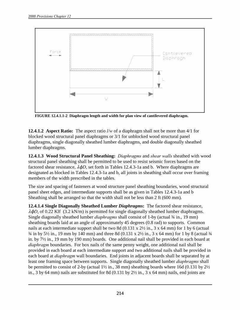
2000 Provisions Chapter 12
214214
FIGURE 12.4.1.1-2 Diaphragm length and width for plan view of cantilevered diaphragm.
12.4.1.2 Aspect Ratio: The aspect ratio l/w of a diaphragm shall not be more than 4/1 forblocked wood structural panel diaphragms or 3/1 for unblocked wood structural paneldiaphragms, single diagonally sheathed lumber diaphragms, and double diagonally sheathedlumber diaphragms.
12.4.1.3 Wood Structural Panel Sheathing: Diaphragms and shear walls sheathed with woodstructural panel sheathing shall be permitted to be used to resist seismic forces based on the factored shear resistance, 8ND, set forth in Tables 12.4.3-1a and b. Where diaphragms aredesignated as blocked in Tables 12.4.3-1a and b, all joints in sheathing shall occur over framingmembers of the width prescribed in the tables.
The size and spacing of fasteners at wood structure panel sheathing boundaries, wood structuralpanel sheet edges, and intermediate supports shall be as given in Tables 12.4.3-1a and bSheathing shall be arranged so that the width shall not be less than 2 ft (600 mm).
12.4.1.4 Single Diagonally Sheathed Lumber Diaphragms: The factored shear resistance,8ND, of 0.22 Klf (3.2 kN/m) is permitted for single diagonally sheathed lumber diaphragms.Single diagonally sheathed lumber diaphragms shall consist of 1-by (actual ¾ in., 19 mm)sheathing boards laid at an angle of approximately 45 degrees (0.8 rad) to supports. Commonnails at each intermediate support shall be two 8d (0.131 x 2½ in., 3 x 64 mm) for 1 by 6 (actual¾ in by 5½ in., 19 mm by 140 mm) and three 8d (0.131 x 2½ in., 3 x 64 mm) for 1 by 8 (actual ¾in. by 7½ in., 19 mm by 190 mm) boards. One additional nail shall be provided in each board atdiaphragm boundaries. For box nails of the same penny weight, one additional nail shall beprovided in each board at each intermediate support and two additional nails shall be provided ineach board at diaphragm wall boundaries. End joints in adjacent boards shall be separated by atleast one framing space between supports. Single diagonally sheathed lumber diaphragms shallbe permitted to consist of 2-by (actual 1½ in., 38 mm) sheathing boards where 16d (0.131 by 2½in., 3 by 64 mm) nails are substituted for 8d (0.131 by 2½ in., 3 x 64 mm) nails, end joints are
Wood Structure Design Requirements
215215
located as above, and the support is not less than 3 in. (actual 2½ in., 64 mm) width or 4 in.(actual 3½ in., 89 mm) depth.
12.4.1.5 Double Diagonally Sheathed Lumber Diaphragms: Double diagonally sheathedlumber diaphragms conform to the requirements for single diagonally sheathed lumberdiaphragms in Sec. 12.4.1.4 and the requirements of this section, and shall be permitted to beused to resist seismic forces based on the factored shear resistance, 8ND, of 0.66 Klf (9.6 kN/m).
Double diagonally sheathed lumber diaphragms shall be sheathed with two layers of diagonalboards placed perpendicular to each other on the same face of the supports. Each chord shall bedesigned for the axial force induced and for flexure between supports due to a uniform load equalto 50 percent of the shear per foot in the diaphragm
12.4.2 Shear Walls:
12.4.2.1 Summing Shear Capacities: The shear values for shear panels of different capacitiesapplied to the same side of the wall are not cumulative except as allowed in Tables 12.4.3-2a and12.4.3.2b. The shear values for material of the same capacity applied to both faces of the samewall are cumulative. Where the material capacities are not equal, the allowable shear shall beeither two times the smaller shear capacity or the capacity of the stronger side, whichever isgreater. Summing shear capacities of dissimilar materials applied to opposite faces or to thesame wall line is not allowed.
12.4.2.2 Adhesives: Adhesive attachment of shear wall sheathing is not permitted.
Exception: Approved adhesive attachment systems shall be permitted in Seismic DesignCategory B where R = 1.5 and S0 = 2.5 unless other values are approved.
12.4.2.3 Aspect Ratio: The shear wall aspect ratio, h/w, shall not exceed 2/1. See Sec. 12.1.3for definitions of w and h.
Exception: Shear wall aspect ratios greater than 2/1, but not exceeding 3.5/1, shall bepermitted provided the factored shear resistance values in Tables 12.4.3-2a and 12.4.3-2b aremultiplied by 2w/h.
12.4.2.4 Shear Wall Anchorage: Where net uplift is induced, tie-down (hold-down) devicesshall be used. Tie-down (hold-down) devices shall be attached to the end posts with nails,screws, or other fasteners. All tie-down devices shall be used only where the uplift resistancevalues are based on cyclic testing of wall assemblies and the test results indicate that the tie-down device does not reduce the stiffness, ductility, or capacity of the shear wall when comparedto nailed-on devices. Nominal strength of the tie-down assemblies shall be equal to or greaterthan the forces resulting from factored resistance values of Tables 12.4.3-2a and 12.4.3-2b timesSo/1.3. The nominal strength of the tie-down device shall be defined as the average maximumtest load the device can resist under cyclic testing without connection failure by either metal orwood failure. The stiffness of the tie-down assemblies shall be such as to prevent prematurefailure of the sheathing fasteners, and the effect of the tie-down displacement shall be included indrift calculations. End posts shall be selected such that failure across the net section of the postis not a limit state for the connection of the tie-down.
2000 Provisions Chapter 12
216216
Foundation anchor bolts shall have a plate washer under each nut. The minimum plate washersizes are as follows:
Plate washer sizeBolt size for shear walls
2 and 5/8 in. 1/4x3x3 in. (13 and 16 mm) (6x75x75 mm)
3/4, 7/8, and 1 in. 3/8x3x3 in.(19, 22, and 25 mm) (10x75x75 mm)
Hole diameters in the plate washer 3/16 in. (5 mm) larger than the bolt diameter are permittedprovided that a standard cut washer is placed between the plate washer and the nut. Foundationanchor bolt embedment shall conform to the requirements of Chapters 6 and 8.
Bolts shall be placed a maximum of 2 in. (50 mm) from the sheathed side of wall sheathed onone face. Walls sheathed on both faces shall have the bolts staggered with the bolt a maximumof 2 in. (50 mm) from either side of the wall. Alternatively, for wall sheathed on both faces, thebolts shall be placed at the center of the foundation sill with the edge of the plate washer within 2in. (13 mm) of each face of the wall. The plate washer width shall be a minimum of 3 in. (75mm) and the plate thickness shall be determined by analysis using the upward force on the plateequal to the tension capacity of the bolt.
Anchor bolt and tie-down nuts shall be tightened without crushing the wood, and provision forpreventing nuts from loosening shall be made just prior to covering the framing.
12.4.2.5 Framing: All framing used for shear wall construction shall conform to PS 20 for 2-by(1.5 in., 38 mm) or larger members.
12.4.2.6 Wood Structural Panel Sheathing: Shear walls sheathed with wood structural panelsheathing shall be permitted to be used to resist seismic forces based on the factored shearresistance, 8ND, set forth in Tables 12.4.2-6a and 12.4.2-6b.
The size and spacing of fasteners at wood structural panel sheathing boundaries, wood structuralpanel sheet edges, and intermediate supports shall be as given in Tables 12.4.2-6a and b.
All panel sheathing joints shall occur over studs or blocking. Sheathing shall be arranged so thatthe width shall not be less than 2 ft (600mm).
Exception: For sheathing attached with the long direction of the panels perpendicular tothe studs, a single sheathing panel with a minimum vertical dimension of 1 ft (300 mm)and a minimum horizontal dimension of 4 ft (1200 mm) is permitted to be used if it islocated at mid-height of the wall, and is fully blocked and nailed.
12.4.2.7 Single Diagonally Sheathed Lumber Shear Walls: Single diagonally sheathedlumber diaphragms are permitted using the construction and resistance provisions of Sec.12.4.1.4.

Wood Structure Design Requirements
217217
12.4.2.8 Double Diagonally Sheathed Lumber Shear Walls: Double diagonally sheathedlumber diaphragms are permitted using the construction and resistance provisions of Sec.12.4.1.5.
12.4.2.9 Shear Walls With Openings Designed for Force Transfer Around Openings: Where structural-use panel shear walls with openings are designed for force transfer around theopenings, the aspect ratio, h/w, limitations of Sec. 12.4.2.3 shall apply to the overall shear wallincluding openings and to each wall pier at the side of an opening. The height of a wall pier shallbe defined as the clear height of the pier at the side of an opening. The width of a wall pier shallbe defined as the sheathed width of the pier. Design and detailing of boundary elements aroundthe opening shall be provided in accordance with Sec. 12.2.1 or ASCE 16. The width of a wallpier shall not be less than 2 ft (610mm).
12.4.3 Perforated Shear Walls: The provisions of Sec. 12.4.3 shall be permitted to be used forthe design of perforated shear walls.
12.4.3.1 Definitions:
Adjusted shear resistance: The unadjusted factored shear resistance multiplied by the shearresistance adjustment factors of Table 12.4.3-1.
Perforated shear wall: A wood structural panel sheathed wall with openings but notspecifically designed and detailed for force transfer around wall openings.
Perforated shear wall segment: A section of shear wall with full height sheathing that meetsthe aspect ratio limits of Sec. 12.4.2.3.
Unadjusted factored shear resistance: The factored shear resistance set forth in Tables 12.4.2-6a and 12.4.2-6b when the aspect ratio of any perforated shear wall segment used in calculationof perforated shear wall resistance does not exceed 2/1. When the aspect ratio of any perforatedshear wall segment used in calculation of perforated shear wall resistance is greater than 2/1, butnot exceeding 3.5/1, the unadjusted factored shear resistance shall be the factored shearresistance set forth in Tables 12.4.2-6a and 12.4.2-6b multiplied by 2w/h.
12.4.3.2 Limitations: The following limitations shall apply to the use of Sec. 12.4.4:
a. A perforated shear wall segment shall be located at each end of a perforated shear wall.Openings shall be permitted to occur beyond the ends of the perforated shear wall, howeverthe width of such openings shall not be included in the width of the perforated shear wall.
b. The factored shear resistance set fort in Tables 12.4.2-6a and 12.4.2-6b shall not exceed 0.64klf (9.4 kN/m).
c. A perforated shear wall shall not have out of plane (horizontal) offsets. Where out of planeoffsets occur, portions of the wall on each side of the offset shall be considered as separateperforated shear walls.
d. Collectors for shear transfer shall be provided through the full length of the perforated shearwall.

2000 Provisions Chapter 12
218218
e. A perforated shear wall shall have uniform top of wall and bottom of wall elevations. Perforated shear walls not having uniform elevations shall be designed by other methods.
f. Perforated shear wall height, h, shall not exceed 20 ft.
12.4.3.3 Perforated Shear Wall Resistance: The resistance of a perforated shear wall shall becalculated in accordance with the following:
12.4.3.3.1 Percent full height sheathing: The percent of full height sheathing shall becalculated as the sum of widths of perforated shear wall segments divided by the total width ofthe perforated shear wall including openings.
12.4.3.3.2 Maximum opening height ratio: The maximum opening height ratio shall becalculated by dividing the maximum opening clear height by the shear wall height, h.
12.4.3.3.3 Adjusted shear resistance: The adjusted shear resistance shall be calculated bymultiplying the unadjusted factored shear resistance by the shear resistance adjustment factors ofTable 12.4.4-1. For intermediate percentages of full height sheathing the values in Table 12.4.4-1 are permitted to be interpolated.
12.4.3.3.4 Perforated shear wall resistance: The perforated shear wall resistance shall beequal to the adjusted shear resistance times the sum of the widths of the perforated shear wallsegments.
12.4.3.4 Anchorage and Load Path: Design of perforated shear wall anchorage and load pathshall conform to the requirements of this section or shall be calculated using principles ofmechanics. Except as modified by this section, wall framing, sheathing, sheathing attachment,and fastener schedules shall conform to the requirements of 12.4.2.6 and Tables 12.4.3-2a and12.4.3-2b.
12.4.3.4.1 Uplift anchorage at perforated shear wall ends: Anchorage for uplift forces due tooverturning shall be provided at each end of the perforated shear wall. The uplift anchorage shallconform to the requirements of Sec. 12.4.2.4 using the factored resistance values set forth inTables 12.4.2-6a and 12.4.2-6b times S0/1.3.
12.4.3.4.2 Anchorage for in-plane shear: The unit shear force ,v, transmitted into the top of aperforated shear wall, out of the base of the perforated shear wall at full height sheathing, andinto collectors (drag struts) connecting shear wall segments, shall be calculated in accordancewith the following:
vV
C Lo i
=∑
where:
v = unit shear force (klf, kN/m),
V = shear force in perforated shear wall (kips, kN),
h = shear wall height (ft, mm/1000),
Wood Structure Design Requirements
219219
Co = shear resistance adjustment factor from Table 12.4.4-1, and
ELi = sum of widths of perforated shear wall segments (ft, mm/1000).
12.4.3.4.3 Uplift anchorage between perforated shear wall ends: In addition to therequirements of Sec. 12.4.4.4.1, perforated shear wall bottom plates at full height sheathing shallbe anchored for a uniform uplift force, t, equal to the unit shear force, v, determined in Sec.12.4.4.4.2.
12.4.3.4.4. Compression chords: Each end of each perforated shear wall segment shall bedesigned for a compression force, C, from each story calculated in accordance with thefollowing:
C = V h / (Co 3 Li)
where:
C = compression chord force (kips, kN),
V = shear force in perforated shear wall (kips, kN),
h = shear wall height (ft, mm/1000),
Co = shear resistance adjustment factor from Table 12.4.4-1, and
3Li = sum of widths of shear wall segments (ft, mm/1000).
12.4.3.4.5. Load path: A load path to the foundation shall be provided for each uplift force, Tand t, for each shear force, v, and for each compression force, C. Elements resisting shear wallforces contributed by multiple stories shall be designed for the sum of forces contributed by eachstory.
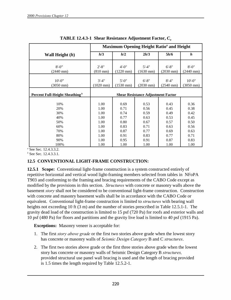
2000 Provisions Chapter 12
220220
TABLE 12.4.3-1 Shear Resistance Adjustment Factor, Co
Maximum Opening Height Ratioa and Height
Wall Height (h) h/3 h/2 2h/3 5h/6 h
8'-0” (2440 mm)
2'-8" (810 mm)
4'-0"(1220 mm)
5'-4"(1630 mm)
6'-8"(2030 mm)
8'-0"(2440 mm)
10'-0” (3050 mm)
3'-4"(1020 mm)
5'-0"(1530 mm)
6'-8"(2030 mm)
8'-4"(2540 mm)
10'-0"(3050 mm)
Percent Full-Height Sheathing b Shear Resistance Adjustment Factor
10%20%30%40%50%60%70%80%90%
100%
1.001.001.001.001.001.001.001.001.001.00
0.690.710.740.770.800.830.870.910.951.00
0.530.560.590.630.670.710.770.830.911.00
0.430.450.490.530.570.630.690.770.871.00
0.360.380.420.450.500.560.630.710.831.00
a See Sec. 12.4.3.3.2.b See Sec. 12.4.3.3.1.
12.5 CONVENTIONAL LIGHT-FRAME CONSTRUCTION:
12.5.1 Scope: Conventional light-frame construction is a system constructed entirely ofrepetitive horizontal and vertical wood light-framing members selected from tables in NFoPAT903 and conforming to the framing and bracing requirements of the CABO Code except asmodified by the provisions in this section. Structures with concrete or masonry walls above thebasement story shall not be considered to be conventional light-frame construction. Constructionwith concrete and masonry basement walls shall be in accordance with the CABO Code orequivalent. Conventional light-frame construction is limited to structures with bearing wallheights not exceeding 10 ft (3 m) and the number of stories prescribed in Table 12.5.1-1. Thegravity dead load of the construction is limited to 15 psf (720 Pa) for roofs and exterior walls and10 psf (480 Pa) for floors and partitions and the gravity live load is limited to 40 psf (1915 Pa).
Exceptions: Masonry veneer is acceptable for:
1. The first story above grade or the first two stories above grade when the lowest storyhas concrete or masonry walls of Seismic Design Category B and C structures.
2. The first two stories above grade or the first three stories above grade when the loweststory has concrete or masonry walls of Seismic Design Category B structures,provided structural use panel wall bracing is used and the length of bracing providedis 1.5 times the length required by Table 12.5.2-1.
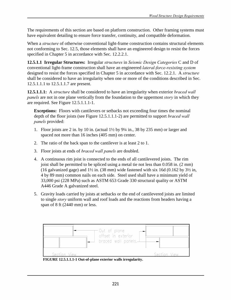
Wood Structure Design Requirements
221221
FIGURE 12.5.1.1.1-1 Out-of-plane exterior walls irregularity.
The requirements of this section are based on platform construction. Other framing systems musthave equivalent detailing to ensure force transfer, continuity, and compatible deformation.
When a structure of otherwise conventional light-frame construction contains structural elementsnot conforming to Sec. 12.5, those elements shall have an engineered design to resist the forcesspecified in Chapter 5 in accordance with Sec. 12.2.2.1.
12.5.1.1 Irregular Structures: Irregular structures in Seismic Design Categories C and D ofconventional light-frame construction shall have an engineered lateral-force-resisting systemdesigned to resist the forces specified in Chapter 5 in accordance with Sec. 12.2.1. A structureshall be considered to have an irregularity when one or more of the conditions described in Sec.12.5.1.1.1 to 12.5.1.1.7 are present.
12.5.1.1.1: A structure shall be considered to have an irregularity when exterior braced wallpanels are not in one plane vertically from the foundation to the uppermost story in which theyare required. See Figure 12.5.1.1.1-1.
Exceptions: Floors with cantilevers or setbacks not exceeding four times the nominaldepth of the floor joists (see Figure 12.5.1.1.1-2) are permitted to support braced wallpanels provided:
1. Floor joists are 2 in. by 10 in. (actual 1½ by 9¼ in., 38 by 235 mm) or larger andspaced not more than 16 inches (405 mm) on center.
2. The ratio of the back span to the cantilever is at least 2 to 1.
3. Floor joists at ends of braced wall panels are doubled.
4. A continuous rim joist is connected to the ends of all cantilevered joists. The rimjoist shall be permitted to be spliced using a metal tie not less than 0.058 in. (2 mm)(16 galvanized gage) and 1½ in. (38 mm) wide fastened with six 16d (0.162 by 3½ in,4 by 89 mm) common nails on each side. Steel used shall have a minimum yield of33,000 psi (228 MPa) such as ASTM 653 Grade 330 structural quality or ASTMA446 Grade A galvanized steel.
5. Gravity loads carried by joists at setbacks or the end of cantilevered joists are limitedto single story uniform wall and roof loads and the reactions from headers having aspan of 8 ft (2440 mm) or less.

2000 Provisions Chapter 12
222222
FIGURE 12.5.1.1.1-2 Cantilever/setback irregularity for exterior walls.
FIGURE 12.5.1.1.2-1 Unsupported diaphragm irregularity.
12.5.1.1.2: A structure shall be considered to have an irregularity when a section of floor orroof is not laterally supported by braced wall lines on all edges. See Figure 12.5.1.1.2-1.
Exception: Portions of roofs or floors that do not support braced wall panels above shallbe permitted to extend up to 6 ft (1830 mm) beyond a braced wall line. See Figure12.5.1.1.2-2.
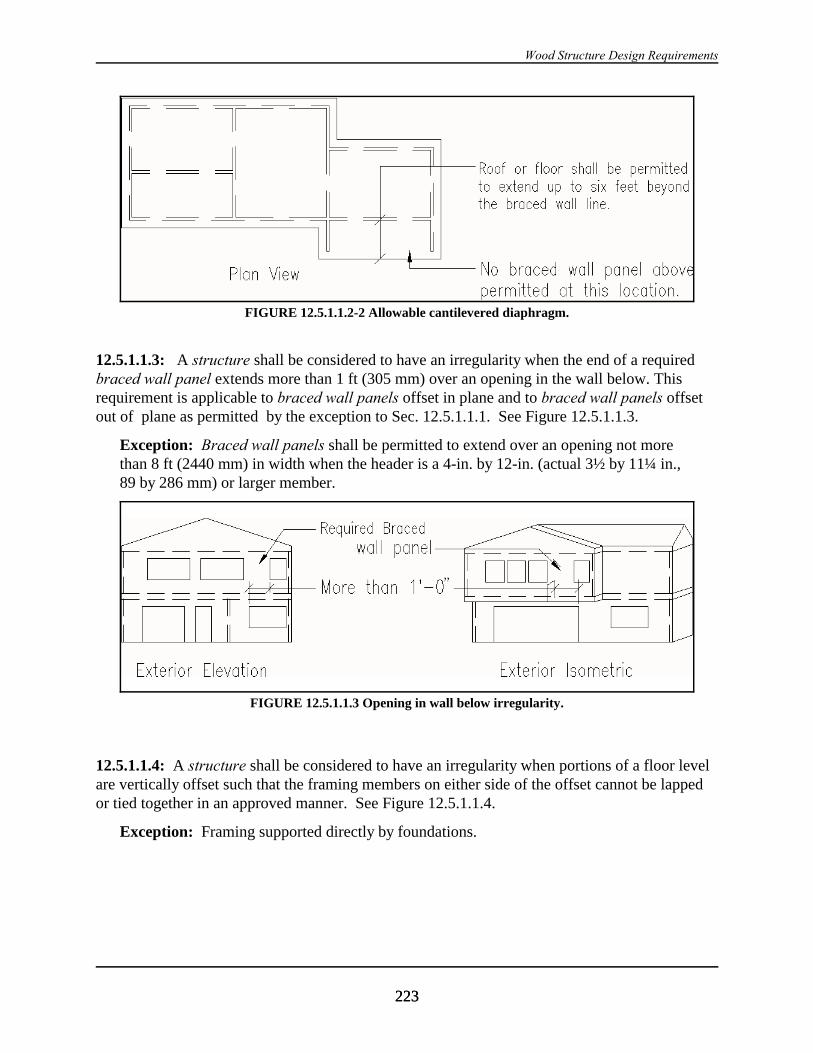
Wood Structure Design Requirements
223223
FIGURE 12.5.1.1.2-2 Allowable cantilevered diaphragm.
FIGURE 12.5.1.1.3 Opening in wall below irregularity.
12.5.1.1.3: A structure shall be considered to have an irregularity when the end of a requiredbraced wall panel extends more than 1 ft (305 mm) over an opening in the wall below. Thisrequirement is applicable to braced wall panels offset in plane and to braced wall panels offsetout of plane as permitted by the exception to Sec. 12.5.1.1.1. See Figure 12.5.1.1.3.
Exception: Braced wall panels shall be permitted to extend over an opening not morethan 8 ft (2440 mm) in width when the header is a 4-in. by 12-in. (actual 3½ by 11¼ in.,89 by 286 mm) or larger member.
12.5.1.1.4: A structure shall be considered to have an irregularity when portions of a floor levelare vertically offset such that the framing members on either side of the offset cannot be lappedor tied together in an approved manner. See Figure 12.5.1.1.4.
Exception: Framing supported directly by foundations.
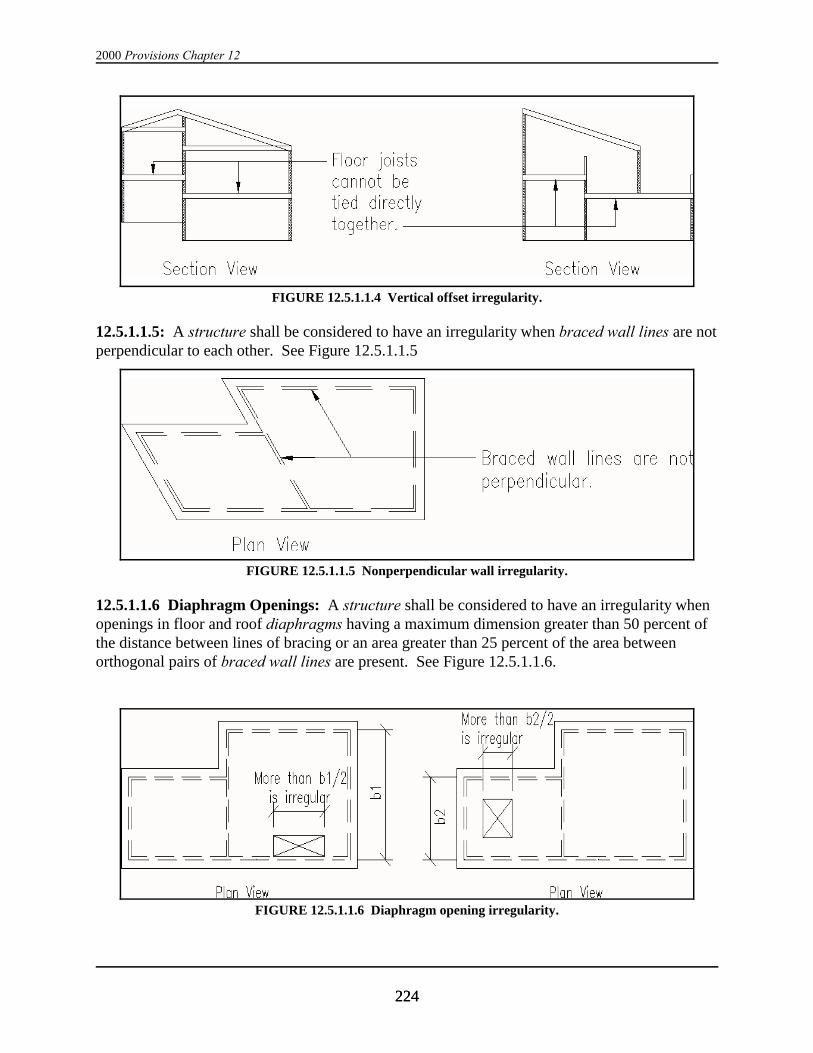
2000 Provisions Chapter 12
224224
FIGURE 12.5.1.1.4 Vertical offset irregularity.
FIGURE 12.5.1.1.5 Nonperpendicular wall irregularity.
FIGURE 12.5.1.1.6 Diaphragm opening irregularity.
12.5.1.1.5: A structure shall be considered to have an irregularity when braced wall lines are notperpendicular to each other. See Figure 12.5.1.1.5
12.5.1.1.6 Diaphragm Openings: A structure shall be considered to have an irregularity whenopenings in floor and roof diaphragms having a maximum dimension greater than 50 percent ofthe distance between lines of bracing or an area greater than 25 percent of the area betweenorthogonal pairs of braced wall lines are present. See Figure 12.5.1.1.6.
Wood Structure Design Requirements
225225
12.5.1.1.7 Stepped Foundation: A structure shall be considered to have an irregularity whenthe shear walls of a single story vary in height more than 6 ft (1800 mm).
12.5.2 Braced Walls: The following are the minimum braced wall requirements.
12.5.2.1 Spacing Between Braced Wall Lines: Interior and exterior braced wall lines shall belocated at the spacing indicated in Table 12.5.1-1.
12.5.2.2 Braced Wall Line Sheathing Requirements: All braced wall lines shall be braced byone of the types of sheathing prescribed in Table 12.5.2-1. The required sum of lengths of b-raced wall panels at each braced wall line is prescribed in Table 12.5.2-1. Braced wall panelsshall be distributed along the length of the braced wall line with sheathing placed at each end ofthe wall or partition or as near thereto as possible. To be considered effective as bracing, eachbraced wall panel shall conform to Sec. 602.9 of the CABO Code. All panel sheathing jointsshall occur over studs or blocking. Sheathing shall be fastened to all studs and top and bottomplates and at panel edges occurring over blocking. All wall framing to which sheathing used forbracing is applied shall be 2-by (actual 1½ in., 38 mm) or larger members.
Cripple walls shall be braced as required for braced wall lines and shall be considered anadditional story. Where interior post and girder framing is used, the capacity of the braced wallpanels at exterior cripple walls shall be increased to compensate for length of interior bracedwall eliminated by increasing the length of the sheathing or increasing the number of fasteners.
12.5.2.3 Attachment:
12.5.2.3.1: Nailing of braced wall panel sheathing shall be not less than the minimum includedin Tables 12.4.2-6a and 12.4.2-6b or as prescribed in Table 12.5.2-1.
12.5.2.3.2: Nailing for diagonal boards shall be as prescribed in Sec. 12.4.3.3 and 12.4.3.4.
12.5.2.3.3 : Adhesive attachment of wall sheathing is not permitted.
12.5.3 Detailing Requirements: The following requirements for framing and connectiondetails shall apply as a minimum.
12.5.3.1 Wall Anchorage: Anchorage of braced wall line sills to concrete or masonryfoundations shall be provided. Such anchorage shall conform to the requirements in Figure403.1a of Sec. 403 of the CABO code except that such anchors shall be spaced at not more than4 ft (1220 mm) on center for structures over two stories in height. For Seismic DesignCategories C, D and E, plate washers, a minimum of ¼ in. by 3 in. by 3 in. in size, shall beprovided between the foundation sill plate and the nut. Other anchorage devices havingequivalent capacity shall be permitted.
12.5.3.2 Top Plates: Stud walls shall be capped with double-top plates installed to provideoverlapping at corners and intersections. End joints in double-top plates shall be offset at least 4ft (1220 mm). Single top plates shall be permitted to be used when they are spliced by framingdevices providing capacity equivalent to the lapped splice prescribed for double top plates.
12.5.3.3 Bottom Plates: Studs shall have full bearing on a 2-by (actual 1½ in., 38 mm) or largerplate or sill having a width at least equal to the width of the studs.
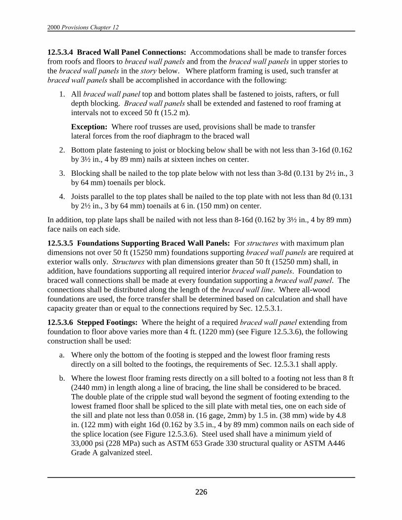
2000 Provisions Chapter 12
226226
12.5.3.4 Braced Wall Panel Connections: Accommodations shall be made to transfer forcesfrom roofs and floors to braced wall panels and from the braced wall panels in upper stories tothe braced wall panels in the story below. Where platform framing is used, such transfer atbraced wall panels shall be accomplished in accordance with the following:
1. All braced wall panel top and bottom plates shall be fastened to joists, rafters, or fulldepth blocking. Braced wall panels shall be extended and fastened to roof framing atintervals not to exceed 50 ft (15.2 m).
Exception: Where roof trusses are used, provisions shall be made to transferlateral forces from the roof diaphragm to the braced wall
2. Bottom plate fastening to joist or blocking below shall be with not less than 3-16d (0.162by 3½ in., 4 by 89 mm) nails at sixteen inches on center.
3. Blocking shall be nailed to the top plate below with not less than 3-8d (0.131 by 2½ in., 3by 64 mm) toenails per block.
4. Joists parallel to the top plates shall be nailed to the top plate with not less than 8d (0.131by 2½ in., 3 by 64 mm) toenails at 6 in. (150 mm) on center.
In addition, top plate laps shall be nailed with not less than 8-16d (0.162 by 3½ in., 4 by 89 mm)face nails on each side.
12.5.3.5 Foundations Supporting Braced Wall Panels: For structures with maximum plandimensions not over 50 ft (15250 mm) foundations supporting braced wall panels are required atexterior walls only. Structures with plan dimensions greater than 50 ft (15250 mm) shall, inaddition, have foundations supporting all required interior braced wall panels. Foundation tobraced wall connections shall be made at every foundation supporting a braced wall panel. Theconnections shall be distributed along the length of the braced wall line. Where all-woodfoundations are used, the force transfer shall be determined based on calculation and shall havecapacity greater than or equal to the connections required by Sec. 12.5.3.1.
12.5.3.6 Stepped Footings: Where the height of a required braced wall panel extending fromfoundation to floor above varies more than 4 ft. (1220 mm) (see Figure 12.5.3.6), the followingconstruction shall be used:
a. Where only the bottom of the footing is stepped and the lowest floor framing restsdirectly on a sill bolted to the footings, the requirements of Sec. 12.5.3.1 shall apply.
b. Where the lowest floor framing rests directly on a sill bolted to a footing not less than 8 ft(2440 mm) in length along a line of bracing, the line shall be considered to be braced. The double plate of the cripple stud wall beyond the segment of footing extending to thelowest framed floor shall be spliced to the sill plate with metal ties, one on each side ofthe sill and plate not less than 0.058 in. (16 gage, 2mm) by 1.5 in. (38 mm) wide by 4.8in. (122 mm) with eight 16d (0.162 by 3.5 in., 4 by 89 mm) common nails on each side ofthe splice location (see Figure 12.5.3.6). Steel used shall have a minimum yield of33,000 psi (228 MPa) such as ASTM 653 Grade 330 structural quality or ASTM A446Grade A galvanized steel.
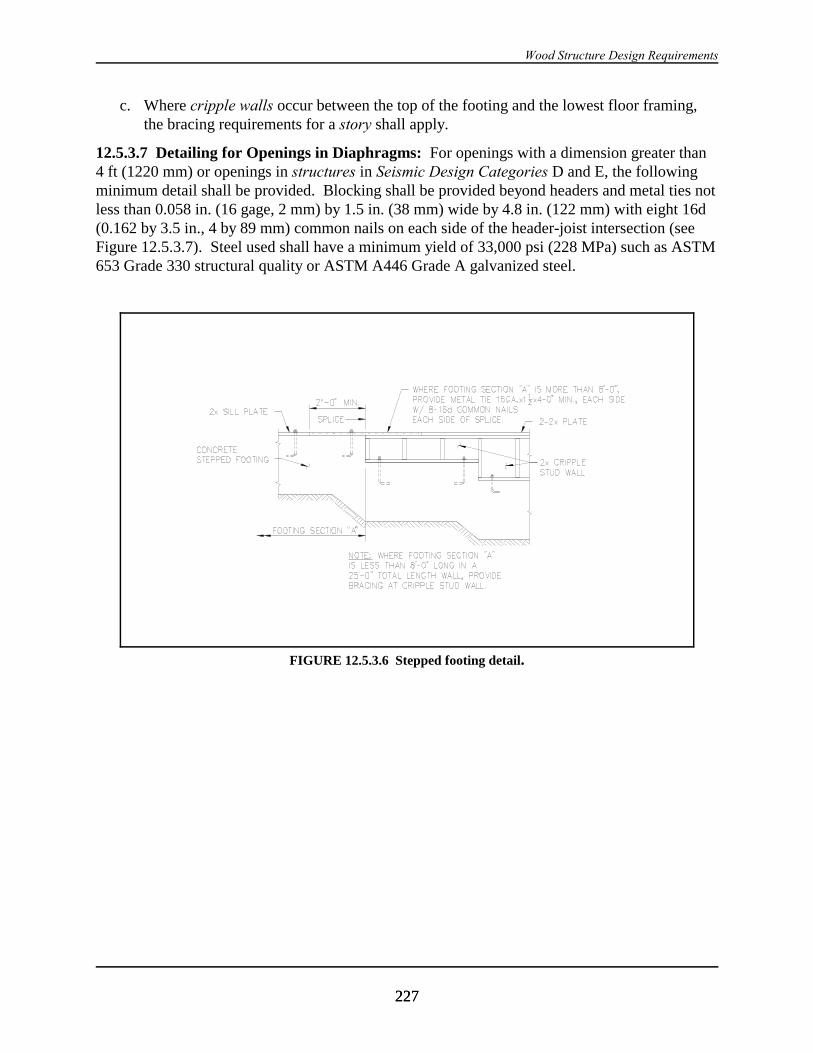
Wood Structure Design Requirements
227227
FIGURE 12.5.3.6 Stepped footing detail.
c. Where cripple walls occur between the top of the footing and the lowest floor framing,the bracing requirements for a story shall apply.
12.5.3.7 Detailing for Openings in Diaphragms: For openings with a dimension greater than4 ft (1220 mm) or openings in structures in Seismic Design Categories D and E, the followingminimum detail shall be provided. Blocking shall be provided beyond headers and metal ties notless than 0.058 in. (16 gage, 2 mm) by 1.5 in. (38 mm) wide by 4.8 in. (122 mm) with eight 16d(0.162 by 3.5 in., 4 by 89 mm) common nails on each side of the header-joist intersection (seeFigure 12.5.3.7). Steel used shall have a minimum yield of 33,000 psi (228 MPa) such as ASTM653 Grade 330 structural quality or ASTM A446 Grade A galvanized steel.
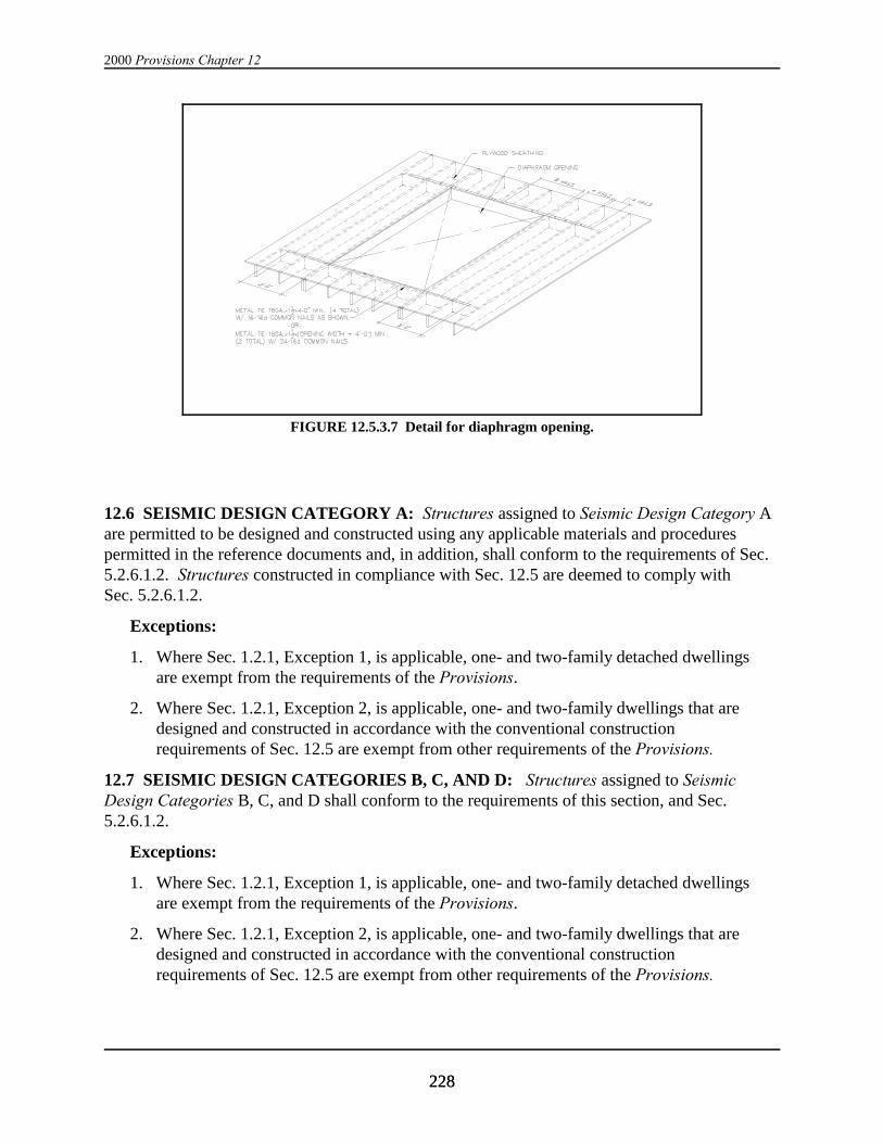
2000 Provisions Chapter 12
228228
FIGURE 12.5.3.7 Detail for diaphragm opening.
12.6 SEISMIC DESIGN CATEGORY A: Structures assigned to Seismic Design Category Aare permitted to be designed and constructed using any applicable materials and procedurespermitted in the reference documents and, in addition, shall conform to the requirements of Sec.5.2.6.1.2. Structures constructed in compliance with Sec. 12.5 are deemed to comply withSec. 5.2.6.1.2.
Exceptions:
1. Where Sec. 1.2.1, Exception 1, is applicable, one- and two-family detached dwellingsare exempt from the requirements of the Provisions.
2. Where Sec. 1.2.1, Exception 2, is applicable, one- and two-family dwellings that aredesigned and constructed in accordance with the conventional constructionrequirements of Sec. 12.5 are exempt from other requirements of the Provisions.
12.7 SEISMIC DESIGN CATEGORIES B, C, AND D: Structures assigned to SeismicDesign Categories B, C, and D shall conform to the requirements of this section, and Sec.5.2.6.1.2.
Exceptions:
1. Where Sec. 1.2.1, Exception 1, is applicable, one- and two-family detached dwellingsare exempt from the requirements of the Provisions.
2. Where Sec. 1.2.1, Exception 2, is applicable, one- and two-family dwellings that aredesigned and constructed in accordance with the conventional constructionrequirements of Sec. 12.5 are exempt from other requirements of the Provisions.

Wood Structure Design Requirements
229229
12.7.1 Conventional Light-Frame Construction: Conventional light-frame construction shallmeet the requirements of Sec. 12.5. Alternatively, such structures shall meet the requirements ofSec. 12.7.2. See Sec. 12.2.2.1 for design of nonconventional elements.
12.7.2 Engineered Construction: All engineered wood construction shall meet therequirements of Sec. 12.3 and 12.4.
12.8 SEISMIC DESIGN CATEGORIES E AND F: Structures assigned to Seismic DesignCategories E and F shall conform to all of the requirements for engineered construction inaccordance with Sec. 12.3 and 12.4 and to the additional requirements of this section.
Exception: Structures assigned to Seismic Use Group I that are designed and constructedin accordance with the requirements of Sec. 12.5 are permitted.
12.8.1 Limitations: Structures shall comply with the requirements given below.
12.8.1.1 Unblocked structural-use panel sheathing diaphragms shall not be considered to bepart of the seismic-force-resisting system. Structural-use panel sheathing used for diaphragmsand shear walls that are part of the seismic-force-resisting system shall be applied directly to theframing members.
Exception: Structural-use panel sheathing may be used as a diaphragm when fastenedover solid lumber planking or laminated decking provided the panel joints and lumberplanking or laminated decking joints do not coincide.
12.8.1.2 In addition to the requirements of Sec. 12.3.4.1, the factored shear resistance, 8ND, forstructural-use panel sheathed shear walls used to resist seismic forces in structures with concreteor masonry walls shall be one-half the values set forth in Tables 12.4.3-2a and 12.4.3-2b.

TABLE 12.4.3-1a Factored Shear Resistance in Kips per Foot for Horizontal Wood Diaphragmswith Framing Members of Douglas Fir-Larch or Southern Pine for Seismic Loadinga,b
Fastenerc Blocked Diaphragms UnblockedDiaphragmsd
Panel Grade Type Minimumpenetration
Minimumnominal
Minimumnominal
Lines ofFastener spacing at diaphragm boundaries (all cases), at continuous panel
edges parallel to load (Cases 3 and 4) and at all panel edges (Cases 5 and 6)eFastener spacing at
6 in. centersat
in framing(in.)
panel thick-ness (in.)
width offraming
fasteners 6 4 2-1/2f 2f supported edges
(in.) Spacing per line at other panel edges (in.)Case
Cases2, 3
6 6 4 4 3 3 21 4, 5,
and 6
Structural I6d
common1-1/4 3/8 2
311
0.240.27
0.330.36
------
0.490.55
------
0.550.62
------
0.210.24
0.160.18
8dcommon
1-3/8 3/8 23
11
0.350.39
0.470.52
------
0.690.78
------
0.780.88
------
0.310.34
0.230.26
10dg
common1-1/2 15/32 2
311
0.420.47
0.550.62
------
0.830.94
------
0.951.07
------
0.370.42
0.280.31
10dg
common1-1/2 23/32 3
44
223
---------
0.850.981.22
1.131.271.70
1.221.401.79
1.601.832.35
---------
---------
---------
---------
14 gaugestaples
2 23/32 34
23
------
0.781.09
0.781.17
1.091.48
1.171.76
1.351.87
1.562.34
------
------
Sheathing,6d common 1-1/4 3/8 2
311
0.240.27
0.330.36
------
0.490.55
------
0.550.62
------
0.210.24
0.160.18
single floor8d common 1-3/8 3/8 2
311
0.310.35
0.420.47
------
0.620.70
------
0.710.79
------
0.280.31
0.210.23
and other7/16 2
311
0.330.37
0.440.49
------
0.660.74
------
0.750.84
------
0.300.33
0.220.25
grades15/32 2
311
0.350.39
0.470.52
------
0.690.78
------
0.780.88
------
0.310.34
0.230.26
covered10dg
common1-1/2 15/32 2
311
0.380.42
0.500.56
------
0.750.85
------
0.850.96
------
0.330.38
0.250.28
in Ref.19/32 2
311
.0420.47
0.550.62
------
0.830.94
------
0.951.07
------
0.370.42
0.280.31
9-10 and 9-1123/32 3
44
223
---------
0.840.981.22
1.131.271.70
1.221.401.78
1.591.811.96
---------
---------
---------
---------
14 gaugestaples
2 23/32 34
23
------
0.781.07
0.781.17
1.071.46
1.171.76
1.331.82
1.561.96
------
------

Wood Structure Design Requirements
231231
NOTES for TABLE 12.4.3-1a
a 8 = 1.0 n = 0.65
b l/w shall not be more than 4/1 for blocked diaphragms or more than 3/1 for unblocked diaphragms. For framingmembers of other species set forth in Ref. 12-1, Table 12A, with the range of specific gravity (SG) noted, allowableshear values shall be calculated for all panel grades by multiplying the values from the table above for nail size andactual panel grade by the following factor: Specific Gravity Adjustment Factor = (1-(0.5 - SG)), Where SG =Specific Gravity of the framing lumber. This adjustment factor shall not be greater than 1.
c Space nails along intermediate framing members at 12 in. centers except where spans aregreater than 32 in..; space nails at 6 in. centers.
d Blocked values are permitted to be used for 1-1/8 in. panels with tongue-and-groove edges where 1 in. by 3/8 in..crown by No. 16 gauge staples are driven through the tongue-and-groove edges 3/8 in. from the panel edge so as topenetrate the tongue. Staples shall be spaced at one half the boundary nail spacing for Cases 1 and 2 and at onethird the boundary nail spacing for Cases 3 through 6.
e Maximum shear for Cases 3 through 6 is limited to 1500 pounds per foot.
f For values listed for 2 in. nominal framing member width, the framing members at adjoining panel edges shall be 3in. nominal width. Nails at panel edges shall be placed in two lines at these locations.
g Framing at adjoining panel edges shall be 3 in. nominal or wider and nails shall be staggered where 10d nailshaving penetration into framing of more than 1-5/8 in. are spaced 3 in. or less on center.
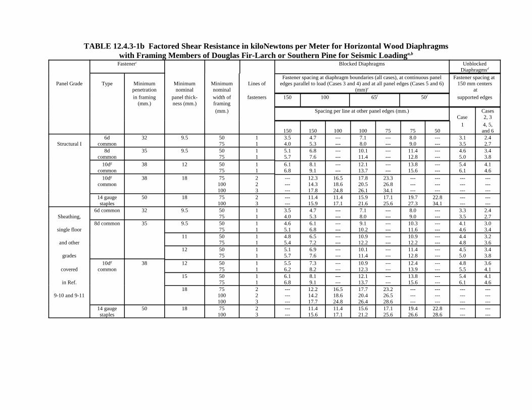
TABLE 12.4.3-1b Factored Shear Resistance in kiloNewtons per Meter for Horizontal Wood Diaphragmswith Framing Members of Douglas Fir-Larch or Southern Pine for Seismic Loadinga,b
Fastenerc Blocked Diaphragms UnblockedDiaphragmsd
Panel Grade Type Minimumpenetration
Minimumnominal
Minimumnominal
Lines ofFastener spacing at diaphragm boundaries (all cases), at continuous panel
edges parallel to load (Cases 3 and 4) and at all panel edges (Cases 5 and 6)(mm)e
Fastener spacing at 150 mm centers
at
in framing(mm.)
panel thick-ness (mm.)
width offraming
fasteners 150 100 65f 50f supported edges
(mm.) Spacing per line at other panel edges (mm.)Case
Cases2, 3
150 150 100 100 75 75 501 4, 5,
and 6
Structural I6d
common32 9.5 50
7511
3.54.0
4.75.3
------
7.18.0
------
8.09.0
------
3.13.5
2.42.7
8dcommon
35 9.5 5075
11
5.15.7
6.87.6
------
10.111.4
------
11.412.8
------
4.65.0
3.43.8
10dg
common38 12 50
7511
6.16.8
8.19.1
------
12.113.7
------
13.815.6
------
5.46.1
4.14.6
10dg
common38 18 75
100100
223
---------
12.314.317.8
16.518.624.8
17.820.526.1
23.326.834.1
---------
---------
---------
---------
14 gaugestaples
50 18 75100
23
------
11.415.9
11.417.1
15.921.6
17.125.6
19.727.3
22.834.1
------
------
Sheathing,6d common 32 9.5 50
7511
3.54.0
4.75.3
------
7.18.0
------
8.09.0
------
3.33.5
2.42.7
single floor8d common 35 9.5 50
7511
4.65.1
6.16.8
------
9.110.2
------
10.311.6
------
4.14.6
3.03.4
and other11 50
7511
4.85.4
6.57.2
------
10.912.2
------
10.912.2
------
4.44.8
3.23.6
grades12 50
7511
5.15.7
6.97.6
------
10.111.4
------
11.412.8
------
4.55.0
3.43.8
covered10dg
common38 12 50
7511
5.56.2
7.38.2
------
10.912.3
------
12.413.9
------
4.85.5
3.64.1
in Ref.15 50
7511
6.16.8
8.19.1
------
12.113.7
------
13.815.6
------
5.46.1
4.14.6
9-10 and 9-1118 75
100100
223
---------
12.214.217.7
16.518.624.8
17.720.426.4
23.226.528.6
---------
---------
---------
---------
14 gaugestaples
50 18 75100
23
------
11.415.6
11.417.1
15.621.2
17.125.6
19.426.6
22.828.6
------
------

Wood Structure Design Requirements
233233
NOTES for TABLE 12.4.3-1b
a 8 = 1.0 n = 0.65
b l/w shall not be more than 4/1 for blocked diaphragms or more than 3/1 for unblocked diaphragms. For framingmembers of other species set forth in ASCE 16, Table 12A, with the range of specific gravity (SG) noted, allowableshear values shall be calculated for all panel grades by multiplying the values from the table above for nail size andactual panel grade by the following factor: Specific Gravity Adjustment Factor = (1-(0.5 - SG)), Where SG = Specific Gravity of the framing lumber. Thisadjustment factor shall not be greater than 1.
c Space nails along intermediate framing members at 300 mm centers except where spans are greater than 810 mm;space nails at 150 mm centers.
d Blocked values are permitted to be used for 28.5 mm panels with tongue-and-groove edges where 25 mm by 9 mmcrown by No. 16 gauge staples are driven through the tongue-and-groove edges 9 mm. from the panel edge so as topenetrate the tongue. Staples shall be spaced at one half the boundary nail spacing for Cases 1 and 2 and at onethird the boundary nail spacing for Cases 3 through 6.
e Maximum shear for Cases 3 through 6 is limited to 22.8 kiloNewtons per meter.
f For values listed for 50 mm nominal framing member width, the framing members at adjoining panel edges shallbe 75 mm nominal width. Nails at panel edges shall be placed in two lines at these locations.
g Framing at adjoining panel edges shall be 75 mm nominal or wider and nails shall be staggered where 10d nailshaving penetration into framing of more than 41 mm are spaced 75 mm or less on center.
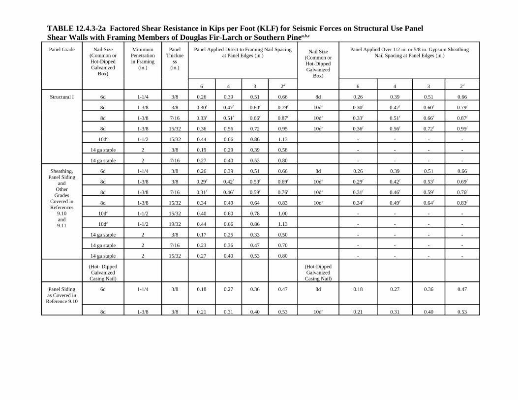
TABLE 12.4.3-2a Factored Shear Resistance in Kips per Foot (KLF) for Seismic Forces on Structural Use PanelShear Walls with Framing Members of Douglas Fir-Larch or Southern Pinea,b,c
Panel Grade Nail Size(Common orHot-DippedGalvanized
Box)
MinimumPenetrationin Framing
(in.)
PanelThickne
ss(in.)
Panel Applied Direct to Framing Nail Spacingat Panel Edges (in.)
Nail Size(Common orHot-DippedGalvanized
Box)
Panel Applied Over 1/2 in. or 5/8 in. Gypsum SheathingNail Spacing at Panel Edges (in.)
6 4 3 2d 6 4 3 2d
Structural I 6d 1-1/4 3/8 0.26 0.39 0.51 0.66 8d 0.26 0.39 0.51 0.66
8d 1-3/8 3/8 0.30f 0.47f 0.60f 0.79f 10de 0.30f 0.47f 0.60f 0.79f
8d 1-3/8 7/16 0.33f 0.51f 0.66f 0.87f 10de 0.33f 0.51f 0.66f 0.87f
8d 1-3/8 15/32 0.36 0.56 0.72 0.95 10de 0.36f 0.56f 0.72f 0.95f
10de 1-1/2 15/32 0.44 0.66 0.86 1.13 - - - -
14 ga staple 2 3/8 0.19 0.29 0.39 0.58 - - - -
14 ga staple 2 7/16 0.27 0.40 0.53 0.80 - - - -
Sheathing,Panel Siding
andOther
GradesCovered inReferences
9.10and9.11
6d 1-1/4 3/8 0.26 0.39 0.51 0.66 8d 0.26 0.39 0.51 0.66
8d 1-3/8 3/8 0.29f 0.42f 0.53f 0.69f 10de 0.29f 0.42f 0.53f 0.69f
8d 1-3/8 7/16 0.31f 0.46f 0.59f 0.76f 10de 0.31f 0.46f 0.59f 0.76f
8d 1-3/8 15/32 0.34 0.49 0.64 0.83 10de 0.34f 0.49f 0.64f 0.83f
10de 1-1/2 15/32 0.40 0.60 0.78 1.00 - - - -
10de 1-1/2 19/32 0.44 0.66 0.86 1.13 - - - -
14 ga staple 2 3/8 0.17 0.25 0.33 0.50 - - - -
14 ga staple 2 7/16 0.23 0.36 0.47 0.70 - - - -
14 ga staple 2 15/32 0.27 0.40 0.53 0.80 - - - -
(Hot- DippedGalvanized
Casing Nail)
(Hot-DippedGalvanized
Casing Nail)
Panel Sidingas Covered in
Reference 9.10
6d 1-1/4 3/8 0.18 0.27 0.36 0.47 8d 0.18 0.27 0.36 0.47
8d 1-3/8 3/8 0.21 0.31 0.40 0.53 10de 0.21 0.31 0.40 0.53
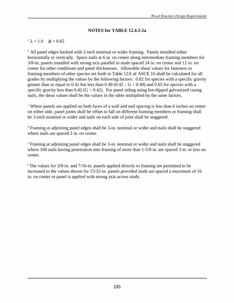
Wood Structure Design Requirements
235235
NOTES for TABLE 12.4.3-2a
a 8 = 1.0 N = 0.65
b All panel edges backed with 2-inch nominal or wider framing. Panels installed eitherhorizontally or vertically. Space nails at 6 in. on center along intermediate framing members for3/8-in. panels installed with strong axis parallel to studs spaced 24 in. on center and 12 in. oncenter for other conditions and panel thicknesses. Allowable shear values for fasteners inframing members of other species set forth in Table 12A of ASCE 16 shall be calculated for allgrades by multiplying the values by the following factors: 0.82 for species with a specific gravitygreater than or equal to 0.42 but less than 0.49 (0.42 # G < 0.49) and 0.65 for species with aspecific gravity less than 0.42 (G < 0.42). For panel siding using hot-dipped galvanized casingnails, the shear values shall be the values in the table multiplied by the same factors.
c Where panels are applied on both faces of a wall and nail spacing is less than 6 inches on centeron either side, panel joints shall be offset to fall on different framing members or framing shallbe 3-inch nominal or wider and nails on each side of joint shall be staggered.
d Framing at adjoining panel edges shall be 3-in. nominal or wider and nails shall be staggeredwhere nails are spaced 2 in. on center.
e Framing at adjoining panel edges shall be 3-in. nominal or wider and nails shall be staggeredwhere 10d nails having penetration into framing of more than 1-5/8 in. are spaced 3 in. or less oncenter.
f The values for 3/8-in. and 7/16-in. panels applied directly to framing are permitted to beincreased to the values shown for 15/32-in. panels provided studs are spaced a maximum of 16in. on center or panel is applied with strong axis across studs.
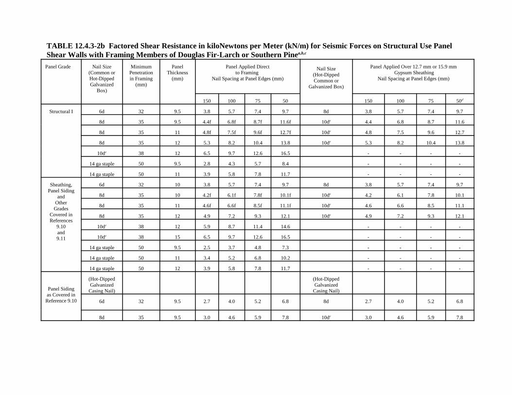
TABLE 12.4.3-2b Factored Shear Resistance in kiloNewtons per Meter (kN/m) for Seismic Forces on Structural Use PanelShear Walls with Framing Members of Douglas Fir-Larch or Southern Pinea,b,c
Panel Grade Nail Size(Common orHot-DippedGalvanized
Box)
MinimumPenetrationin Framing
(mm)
PanelThickness
(mm)
Panel Applied Directto Framing
Nail Spacing at Panel Edges (mm)
Nail Size(Hot-DippedCommon or
Galvanized Box)
Panel Applied Over 12.7 mm or 15.9 mm Gypsum Sheathing
Nail Spacing at Panel Edges (mm)
150 100 75 50 150 100 75 50d
Structural I 6d 32 9.5 3.8 5.7 7.4 9.7 8d 3.8 5.7 7.4 9.7
8d 35 9.5 4.4f 6.8f 8.7f 11.6f 10de 4.4 6.8 8.7 11.6
8d 35 11 4.8f 7.5f 9.6f 12.7f 10de 4.8 7.5 9.6 12.7
8d 35 12 5.3 8.2 10.4 13.8 10de 5.3 8.2 10.4 13.8
10de 38 12 6.5 9.7 12.6 16.5 - - - -
14 ga staple 50 9.5 2.8 4.3 5.7 8.4 - - - -
14 ga staple 50 11 3.9 5.8 7.8 11.7 - - - -
Sheathing,Panel Siding
andOther
GradesCovered inReferences
9.10and9.11
6d 32 10 3.8 5.7 7.4 9.7 8d 3.8 5.7 7.4 9.7
8d 35 10 4.2f 6.1f 7.8f 10.1f 10de 4.2 6.1 7.8 10.1
8d 35 11 4.6f 6.6f 8.5f 11.1f 10de 4.6 6.6 8.5 11.1
8d 35 12 4.9 7.2 9.3 12.1 10de 4.9 7.2 9.3 12.1
10de 38 12 5.9 8.7 11.4 14.6 - - - -
10de 38 15 6.5 9.7 12.6 16.5 - - - -
14 ga staple 50 9.5 2.5 3.7 4.8 7.3 - - - -
14 ga staple 50 11 3.4 5.2 6.8 10.2 - - - -
14 ga staple 50 12 3.9 5.8 7.8 11.7 - - - -
Panel Sidingas Covered in
Reference 9.10
(Hot-DippedGalvanized
Casing Nail)
(Hot-DippedGalvanized
Casing Nail)
6d 32 9.5 2.7 4.0 5.2 6.8 8d 2.7 4.0 5.2 6.8
8d 35 9.5 3.0 4.6 5.9 7.8 10de 3.0 4.6 5.9 7.8
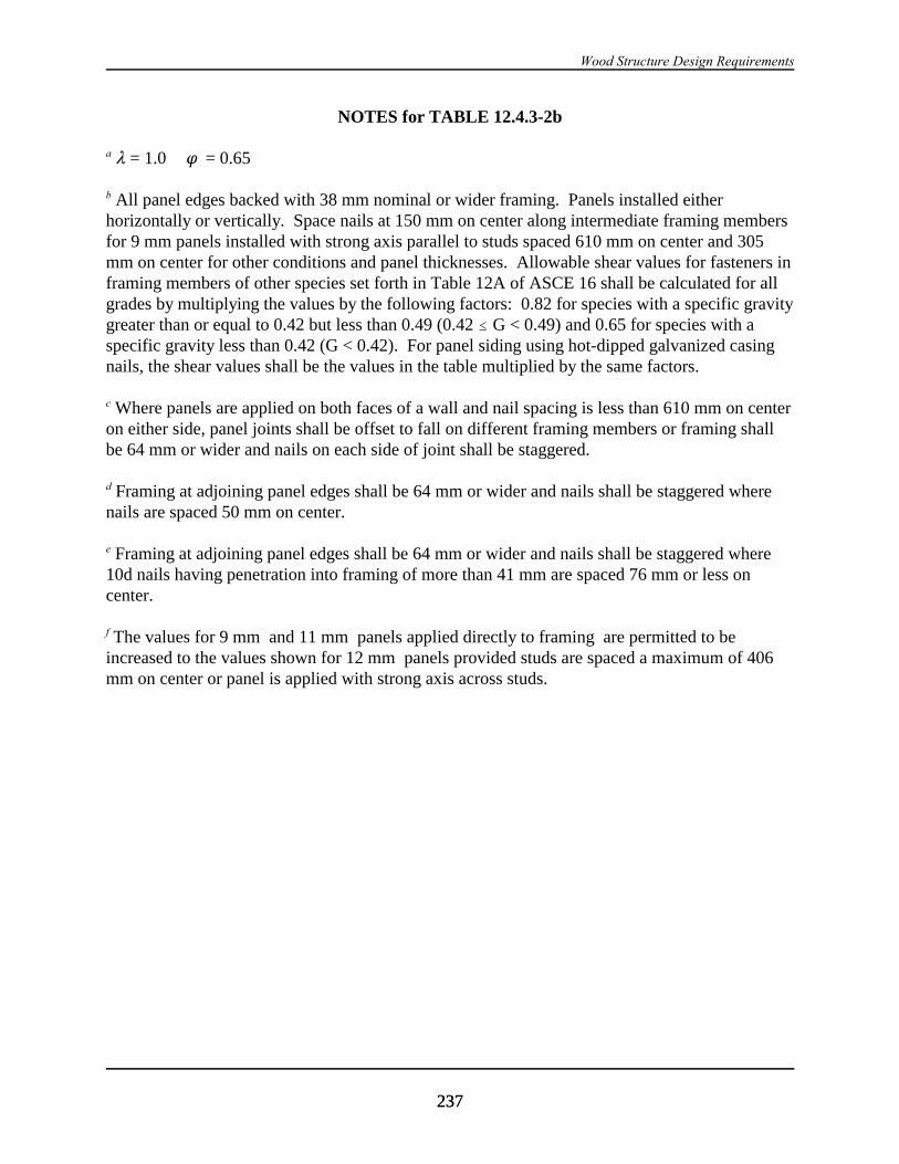
Wood Structure Design Requirements
237237
NOTES for TABLE 12.4.3-2b
a 8 = 1.0 n = 0.65
b All panel edges backed with 38 mm nominal or wider framing. Panels installed eitherhorizontally or vertically. Space nails at 150 mm on center along intermediate framing membersfor 9 mm panels installed with strong axis parallel to studs spaced 610 mm on center and 305mm on center for other conditions and panel thicknesses. Allowable shear values for fasteners inframing members of other species set forth in Table 12A of ASCE 16 shall be calculated for allgrades by multiplying the values by the following factors: 0.82 for species with a specific gravitygreater than or equal to 0.42 but less than 0.49 (0.42 # G < 0.49) and 0.65 for species with aspecific gravity less than 0.42 (G < 0.42). For panel siding using hot-dipped galvanized casingnails, the shear values shall be the values in the table multiplied by the same factors.
c Where panels are applied on both faces of a wall and nail spacing is less than 610 mm on centeron either side, panel joints shall be offset to fall on different framing members or framing shallbe 64 mm or wider and nails on each side of joint shall be staggered.
d Framing at adjoining panel edges shall be 64 mm or wider and nails shall be staggered wherenails are spaced 50 mm on center.
e Framing at adjoining panel edges shall be 64 mm or wider and nails shall be staggered where10d nails having penetration into framing of more than 41 mm are spaced 76 mm or less oncenter.
f The values for 9 mm and 11 mm panels applied directly to framing are permitted to beincreased to the values shown for 12 mm panels provided studs are spaced a maximum of 406mm on center or panel is applied with strong axis across studs.
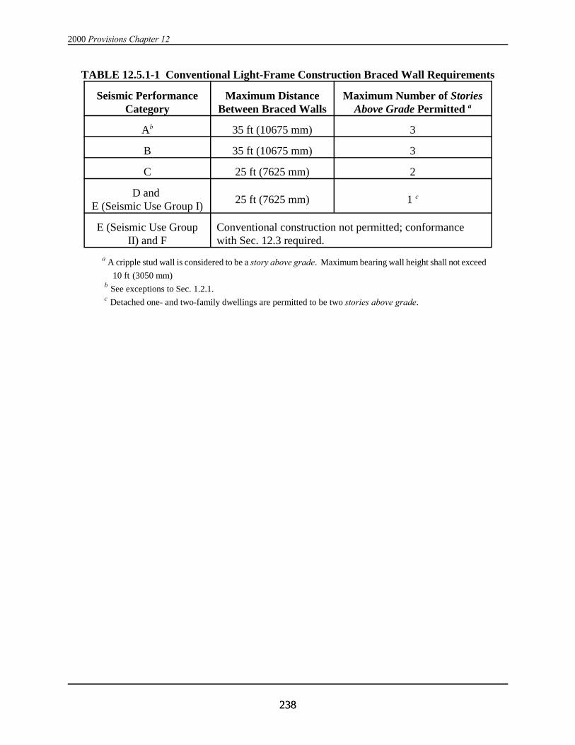
2000 Provisions Chapter 12
238238
TABLE 12.5.1-1 Conventional Light-Frame Construction Braced Wall Requirements
Seismic PerformanceCategory
Maximum DistanceBetween Braced Walls
Maximum Number of StoriesAbove Grade Permitted a
Ab 35 ft (10675 mm) 3
B 35 ft (10675 mm) 3
C 25 ft (7625 mm) 2
D and E (Seismic Use Group I)
25 ft (7625 mm) 1 c
E (Seismic Use GroupII) and F
Conventional construction not permitted; conformancewith Sec. 12.3 required.
a A cripple stud wall is considered to be a story above grade. Maximum bearing wall height shall not exceed
10 ft (3050 mm)
b See exceptions to Sec. 1.2.1.
c Detached one- and two-family dwellings are permitted to be two stories above grade.

Wood Structure Design Requirements
239239
TABLE 12.5.2-1 Conventional Light-Frame Construction Braced Wall Requirementsin Minimum Length of Wall Bracing per Each 25 Lineal Feet (7625 mm) of Braced Wall
Linea
StoryLoca-tion
SheathingTypeb
0.125 ####SDS < 0.25
0.25 #### SDS < 0.375
0.375 #### SDS < 0.50
0.50 #### SDS < 0.75
0.75 #### SDS
< 1.0e
Top oronlystoryabovegrade
G-Pd 8 ft 0 in.(2440 mm)
8 ft 0 in.(2440 mm)
10 ft 8 in.(3250 mm)
14 ft 8 in.(4470 mm)
18 ft 8 in.c
(5690 mm)
S-W 4 ft 0 in.(1220 mm)
4 ft 0 in.(1220 mm)
5 ft 4 in.(1625 mm)
8 ft 0 in.(2440 mm)
9 ft 4 in.c
(2845 mm)
Story be-low topstoryabovegrade
G-Pd 10 ft 8 in(3250 mm)
14 ft 8 in.(4470 mm)
18 ft 8 in.c
(6590 mm)NP NP
S-W 5 ft 4 in.(1625 mm)
6 ft 8 in.(2030 mm)
10 ft 8 in.c
(3250 mm)13 ft 4 in.c
(4065 mm)17 ft 4 in.c
(5280 mm)
Bottomstory of3 storiesabovegrade
G-Pd 14 ft 8 in.(4470 mm)
Conventional construction not permitted;conformance with Sec. 12.3 required.
S-W 8 ft 0 in.(2440 mm)
a Minimum length of panel bracing of one face of wall for S-W sheathing or both faces of wall for G-Psheathing; h/w ratio shall not exceed 2/1, except structures in Seismic Design Category B need only meet therequirements of Sec. 602.9 of the CABO Code. For S-W panel bracing of the same material on two faces of thewall, the minimum length is permitted to be one half the tabulated value but the h/w ratio shall not exceed 2/1 anddesign for uplift is required.
b G-P = gypsumboard, fiberboard, particleboard, lath and plaster, or gypsum sheathing boards; S-W =structural-use panels and diagonal wood sheathing. NP = not permitted.
c Applies to one- and two-family detached dwellings only.
d Nailing shall be as follows:For ½ in. (13 mm) gypsum board, 5d ( 0.086 in., 2.2 mm diameter) coolers at 7 in. (178 mm) centers;For e in. (16mm) gypsum board, 6d ( 0.092 in. ( 2.3 mm) diameter) at 7 in (178 mm) centers;For gypsum sheathing board, 1¾ in. long by 7/16 in. (44 by 11 mm) head, diamond point galvanized at 4 in.(100mm) centers;For gypsum lath, No. 13 gauge (0.092 in., 2.3 mm) by 1c in. long, 19/64 in. (29 by 7.5 mm) head, plasterboardat 5 in. (125 mm) centers;For Portland cement plaster, No. 11 gauge (0.120 in., 3 mm) by 1½ in. long, 7/16 in. head (89 by 11 mm) at 6 in.(150 mm) centers; For fiberboard and particleboard, No. 11 gauge (0.120 in., 3 mm) by 1½ in. (38 mm) long, 7/16 in. ( 11 mm)head, galvanized at 3 in. (76 mm) centers. For structural wood sheathing, the minimum nail size and maximum spacing shall be in accordance with theminimum nails size and maximum spacing allowed for each thickness sheathing in Tables 12.4.3-2a and b. Nailing as specified above shall occur at all panel edges at studs, at top and bottom plates, and, whereoccurring, at blocking. e Where SDS > 1.0, conventional construction is not permitted.


241241
Chapter 13
SEISMICALLY ISOLATED STRUCTURES DESIGN REQUIREMENTS
13.1 GENERAL: Every seismically isolated structure and every portion thereof shall bedesigned and constructed in accordance with the requirements of this section and the applicablerequirements of Chapter 1. The lateral-force-resisting system and the isolation system shall bedesigned to resist the deformations and stresses produced by the effects of seismic groundmotions as provided in this section.
13.2 CRITERIA SELECTION:
13.2.1 Basis for Design: The procedures and limitations for the design of seismically isolatedstructures shall be determined considering zoning, site characteristics, vertical acceleration,cracked section properties of concrete and masonry members, Seismic Use Group, configuration,structural system, and height in accordance with Sec. 5.2 except as noted below.
13.2.2 Stability of the Isolation System: The stability of the vertical load-carrying elements ofthe isolation system shall be verified by analysis and test, as required, for lateral seismicdisplacement equal to the total maximum displacement.
13.2.3 Seismic Use Group: All portions of the structure, including the structure above theisolation system, shall be assigned a Seismic Use Group in accordance with the requirements ofSec. 1.3. The Occupancy Importance Factor shall be taken as 1.0 for a seismically isolatedstructure, regardless of its Seismic Use Group categorization. The Component Importance Factorshall be selected in accordance with Sec. 6.1.5.
13.2.4 Configuration Requirements: Each structure shall be designated as being regular orirregular on the basis of the structural configuration above the isolation system in accordancewith the requirements of Sec. 5.2.
13.2.5 Selection of Lateral Response Procedure:
13.2.5.1 General: Any seismically isolated structure is permitted to be and certain seismicallyisolated structures defined below shall be designed using the dynamic lateral response procedureof Sec. 13.4.
13.2.5.2 Equivalent Lateral Force Procedure: The equivalent-lateral-response procedure ofSec. 13.3 is permitted to be used for design of a seismically isolated structure provided that:
1. The structure is located at a site with S1 less than or equal to 0.60 ;
2. The structure is located on a Class A, B, C, or D site;
3. The structure above the isolation interface is not more than four stories or 65 ft (20 m) inheight;
4. The effective period of the isolated structure, TM, is less than or equal to 3.0 sec.

2000 Provisions Chapter 13
242242
5. The effective period of the isolated structure, TD, is greater than three times the elastic, fixed-base period of the structure above the isolation system as determined by Eq. 5.4.2.1-1 or5.4.2.1-2;
6. The structure above the isolation system is of regular configuration; and
7. The isolation system meets all of the following criteria:
a. The effective stiffness of the isolation system at the design displacement is greater thanone third of the effective stiffness at 20 percent of the design displacement,
b. The isolation system is capable of producing a restoring force as specified in Sec.13.6.2.4,
c. The isolation system has force-deflection properties that are independent of the rate ofloading,
d. The isolation system has force-deflection properties that are independent of vertical loadand bilateral load, and
e. The isolation system does not limit maximum capable earthquake displacement to lessthan SM1/SD1 times the total design displacement.
13.2.5.3 Dynamic Analysis: A dynamic analysis is permitted to be used for the design of anystructure but shall be used for the design of all isolated structures not satisfying Sec. 13.2.5.2.The dynamic lateral response procedure of Sec. 13.4 shall be used for design of seismicallyisolated structures as specified below.
13.2.5.3.1 Response-Spectrum Analysis: Response-spectrum analysis is permitted to be usedfor design of a seismically isolated structure provided that:
1. The structure is located on a Class A, B, C, or D site and
2. The isolation system meets the criteria of Item 7 of Sec. 13.2.5.2.
13.2.5.3.2 Time-History Analysis: Time-history analysis is permitted to be used for design ofany seismically isolated structure and shall be used for design of all seismically isolatedstructures not meeting the criteria of Sec. 13.2.5.3.1.
13.2.5.3.3 Site-Specific Design Spectra: Site-specific ground-motion spectra of the designearthquake and the maximum considered earthquake developed in accordance with Sec. 13.4.4.1shall be used for design and analysis of all seismically isolated structures if any one of thefollowing conditions apply:
1. The structure is located on a Class F site or
2. The structure is located at a site with S1 greater than 0.60 .

Base Isolation and Energy Dissipation
243243
DD 'g
4B2
SD1 TD
BD
(13.3.3.1)
13.3 EQUIVALENT LATERAL FORCE PROCEDURE:
13.3.1 General: Except as provided in Sec. 13.4, every seismically isolated structure or portionthereof shall be designed and constructed to resist minimum earthquake displacements and forcesas specified by this section and the applicable requirements of Sec. 5.4.
13.3.2 Deformation Characteristics of the Isolation System: Minimum lateral earthquakedesign displacement and forces on seismically isolated structures shall be based on thedeformation characteristics of the isolation system. The deformation characteristics of theisolation system shall explicitly include the effects of the wind-restraint system if such a systemis used to meet the design requirements of these Provisions. The deformation characteristics ofthe isolation system shall be based on properly substantiated tests performed in accordance withSec. 13.9.
13.3.3 Minimum Lateral Displacements:
13.3.3.1 Design Displacement: The isolation system shall be designed and constructed towithstand minimum lateral earthquake displacements that act in the direction of each of the mainhorizontal axes of the structure in accordance with the following:
where:
g = acceleration of gravity. The units of the acceleration of gravity, g, are in./sec2
(mm/sec2) if the units of the design displacement, DD, are inches (mm);
SD1 = design 5 percent damped spectral acceleration at 1 sec period as determined in Sec.4.1.1;
TD = effective period, in seconds (sec), of seismically isolated structure at the designdisplacement in the direction under consideration, as prescribed by Eq. 13.3.3.2; and
BD = numerical coefficient related to the effective damping of the isolation system at thedesign displacement, $D, as set forth in Table 13.3.3.1.
TABLE 13.3.3.1 Damping Coefficient, BD or BM
Effective Damping, $$$$D or $$$$M
(Percentage of Critical)a,bBD or BM
Factor # 2% 0.8
5% 1.010% 1.220% 1.530% 1.740% 1.9
$ 50% 2.0

2000 Provisions Chapter 13
244244
TD ' 2B WkDmin g
(13.3.3.2)
DM '
g
4B2SM1 TM
B
(13.3.3.3)
NOTES for Table 13.3.3.1 a The damping coefficient shall be based on the effective damping of theisolation system determined in accordance with the requirements of Sec.13.9.5.2.
b The damping coefficient shall be based on linear interpolation for effectivedamping values other than those given.
13.3.3.2 Effective Period: The effective period of the isolated structure, TD, shall be determinedusing the deformational characteristics of the isolation system in accordance with the followingequation:
where:
W = total seismic dead load weight of the structure above the isolation interface asdefined in Sec. 5.4.1 and 5.5.3 (kip or kN);
kDmin = minimum effective stiffness, in kips/inch (kN/mm), of the isolation system at thedesign displacement in the horizontal direction under consideration asprescribed by Eq. 13.9.5.1-2; and
g = acceleration of gravity. The units of the acceleration of gravity, g, are in./sec2
(mm/sec2) if the units of the design displacement, DD, are inches (mm).
13.3.3.3 Maximum Displacement: The maximum displacement of the isolation system, DM, inthe most critical direction of horizontal response shall be calculated in accordance with theformula:
where:
g = acceleration of gravity. The units of the acceleration of gravity, g, are in./sec2
(mm/sec2) if the units of the design displacement, DD, are inches (mm);
SM1 = maximum considered 5 percent damped spectral acceleration at 1 sec period asdetermined in Sec. 4.1.1;

Base Isolation and Energy Dissipation
245245
TM ' 2B WkMming
(13.3.3.4)
DTM ' DM 1 % y12e
b 2 % d 2(13.3.3.5-2)
DTD ' DD 1 % y12e
b 2 % d 2(13.3.3.5-1)
TM = effective period, in seconds (sec), of seismic-isolated structure at the maximumdisplacement in the direction under consideration as prescribed by Eq. 13.3.3.4;and
BM = numerical coefficient related to the effective damping of the isolation system atthe maximum displacement, $D, as set forth in Table 13.3.3.1.
13.3.3.4 Effective Period at Maximum Displacement: The effective period of the isolatedstructure at maximum displacement, TM, shall be determined using the deformationalcharacteristics of the isolation system in accordance with the equation:
where:
W = total seismic dead load weight of the structure above the isolation interface asdefined in Sec. 5.3.2 and 5.5.3 (kip or kN);
kMmin = minimum effective stiffness, in kips/inch (kN/mm), of the isolation system at themaximum displacement in the horizontal direction under consideration asprescribed by Eq. 13.9.5.1-4; and
g = the acceleration due to gravity. The units of the acceleration of gravity, g, arein./sec2 (mm/sec2) if the units of the design displacement, DD, are inches (mm).
13.3.3.5 Total Displacement: The total design displacement, DTD, and the total maximumdisplacement, DTM, of elements of the isolation system shall include additional displacement dueto actual and accidental torsion calculated considering the spatial distribution of the lateralstiffness of the isolation system and the most disadvantageous location of mass eccentricity.
The total design displacement, DTD, and the total maximum displacement, DTM, of elements of anisolation system with uniform spatial distribution of lateral stiffness shall not be taken as lessthan that prescribed by the following equations:
where:
DD = design displacement, in inches (mm), at the center of rigidity of the isolation systemin the direction under consideration as prescribed by Eq. 13.3.3.1;

2000 Provisions Chapter 13
246246
Vb ' kDmax DD (13.3.4.1)
DM = maximum displacement, in inches (mm), at the center of rigidity of the isolationsystem in the direction under consideration as prescribed in Eq. 13.3.3.3;
y = the distance, in feet (mm), between the center of rigidity of the isolation systemrigidity and the element of interest measured perpendicular to the direction ofseismic loading under consideration;
e = the actual eccentricity, in feet (mm), measured in plan between the center of mass ofthe structure above the isolation interface and the center of rigidity of the isolationsystem, plus accidental eccentricity, in feet (mm), taken as 5 percent of the longestplan dimension of the structure perpendicular to the direction of force underconsideration,
b = the shortest plan dimension of the structure, in feet (mm), measured perpendicular tod, and
d = the longest plan dimension of the structure, in feet (mm).
The total design displacement, DTD, and the total maximum displacement, DTM, is permitted to betaken as less than the value prescribed by Eq. 13.3.3.5-1 and Eq. 13.3.3.5-2, respectively, but notless than 1.1 times DD and DM, respectively, provided the isolation system is shown bycalculation to be configured to resist torsion accordingly.
13.3.4 Minimum Lateral Forces:
13.3.4.1 Isolation System and Structural Elements At or Below the Isolation System: Theisolation system, the foundation, and all structural elements below the isolation system shall bedesigned and constructed to withstand a minimum lateral seismic force, Vb, using all of theappropriate provisions for a nonisolated structure where:
where:
kDmax = maximum effective stiffness, in kips/inch (kN/mm), of the isolation system atthe design displacement in the horizontal direction under consideration asprescribed by Eq. 13.9.5.1-1, and
DD = design displacement, in inches (mm), at the center of rigidity of the isolationsystem in the direction under consideration as prescribed by Eq. 13.3.3.1.
In all cases, Vb shall not be taken as less than the maximum force in the isolation system at anydisplacement up to and including the design displacement.

Base Isolation and Energy Dissipation
247247
Vs 'kDmax DD
RI
(13.3.4.2)
Fx 'Vs wx hx
jn
i'1
wi hi
(13.3.5)
13.3.4.2 Structural Elements Above the Isolation System: The structure above the isolationsystem shall be designed and constructed to withstand a minimum shear force, Vs, using all of theappropriate provisions for a nonisolated structure where:
where:
kDmax = maximum effective stiffness, in kips/inch (kN/mm), of the isolation system atthe design displacement in the horizontal direction under consideration asprescribed by Eq. 13.9.5.1-1;
DD = design displacement, in inches (mm), at the center of rigidity of the isolationsystem in the direction under consideration as prescribed by Eq. 13.3.3.1; and
RI = numerical coefficient related to the type of lateral-force-resisting system abovethe isolation system.
The RI factor shall be based on the type of lateral-force-resisting system used for the structureabove the isolation system and shall be 3/8 of the R value given in Table 5.2.2 with an upperbound value not to exceed 2.0 and a lower bound value not to be less than 1.0.
13.3.4.3 Limits on Vs: The value of Vs shall be taken as not less than the following:
1. The lateral seismic force required by Sec. 5.3 for a fixed-base structure of the same weight,W, and a period equal to the isolated period, TD;
2. The base shear corresponding to the factored design wind load; and
3. The lateral seismic force required to fully activate the isolation system (e.g., the yield level ofa softening system, the ultimate capacity of a sacrificial wind-restraint system, or the break-away friction level of a sliding system) factored by 1.5.
13.3.5 Vertical Distribution of Force: The total force shall be distributed over the height ofthe structure above the isolation interface in accordance with the following equation:
where:
Vs = total lateral seismic design force or shear on elements above the isolation systemas prescribed by Eq. 13.3.4.2;
Wx = portion of W that is located at or assigned to Level x;.

2000 Provisions Chapter 13
248248
D )
D 'DD
1 %TTD
2 (13.4.2-1)
D )
M 'DM
1 %T
TM
2 (13.4.2-2)
hx = height above the base Level x;
wi = portion of W that is located at or assigned to Level I , respectively; and
hi = height above the base Level I .
At each level designated as x, the force, Fx, shall be applied over the area of the structure inaccordance with the mass distribution at the level. Stresses in each structural element shall becalculated as the effect of force, Fx, applied at the appropriate levels above the base.
13.3.6 Drift Limits: The maximum interstory drift of the structure above the isolation systemshall not exceed 0.015hsx. The drift shall be calculated by Eq. 5.4.6-1 with the Cd factor of theisolated structure equal to the RI factor defined in Sec. 13.3.4.2.
13.4 DYNAMIC LATERAL RESPONSE PROCEDURE:
13.4.1 General: As required by Sec. 13.2, every seismically isolated structure or portionthereof shall be designed and constructed to resist earthquake displacements and forces asspecified in this section and the applicable requirements of Sec. 5.5.
13.4.2 Isolation System and Structural Elements Below the Isolation System: The totaldesign displacement of the isolation system shall be taken as not less than 90 percent of DTD asspecified by Sec. 13.3.3.5.
The total maximum displacement of the isolation system shall be taken as not less than 80percent of DTM as specified by Sec. 13.3.3.5 .
The design lateral shear force on the isolation system and structural elements below the isolationsystem shall be taken as not less than 90 percent of Vb as prescribed by Eq. 13.3.4.1.
The limits of the first and second paragraphs of Sec. 13.4.2 shall be evaluated using values ofDTD and DTM determined in accordance with Sec. 13.3.3 except that is permitted to be used inD )
Dlieu of DD and is permitted to be used in lieu of DM where and D!M are prescribed by theD )
M D )
Dfollowing equations:
Base Isolation and Energy Dissipation
249249
where:
DD = design displacement, in inches (mm), at the center of rigidity of the isolation systemin the direction under consideration as prescribed by Eq. 13.3.3.1;
DM = maximum displacement in inches (mm), at the center of rigidity of the isolationsystem in the direction under consideration as prescribed by Eq. 13.3.3.3;
T = elastic, fixed-base period of the structure above the isolation system as determinedby Sec. 5.3.3;
TD = effective period, in seconds (sec), of the seismically isolated structure at the designdisplacement in the direction under consideration as prescribed by Eq. 13.3.3.2; and
TM = effective period, in seconds (sec), of the seismically isolated structure at themaximum displacement in the direction under consideration as prescribed by Eq.13.3.3.4.
13.4.3 Structural Elements Above the Isolation System: The design lateral shear force on thestructure above the isolation system, if regular in configuration, shall be taken as not less than 80percent of Vs, as prescribed by Eq. 13.3.4.2 and the limits specified by Sec. 13.3.4.3.
Exception: The design lateral shear force on the structure above the isolation system, ifregular in configuration, is permitted to be taken as less than 80 percent, but not less than60 percent of Vs, provided time-history analysis is used for design of the structure.
The design lateral shear force on the structure above the isolation system, if irregular inconfiguration, shall be taken as not less than Vs, as prescribed by Eq. 13.3.4.2 and the limitsspecified by Sec. 13.3.4.3.
Exception: The design lateral shear force on the structure above the isolation system, ifirregular in configuration, is permitted to be taken as less than 100 percent, but not lessthan 80 percent of Vs, provided time-history analysis is used for design of the structure.
13.4.4 Ground Motion:
13.4.4.1 Design Spectra: Properly substantiated site-specific spectra are required for the designof all structures located on a Class F site or located at a site with S1 greater than 0.60 . Structuresthat do not require site-specific spectra and for which site specific spectra have not beencalculated shall be designed using the response spectrum shape given in Figure 4.1.2.6.
A design spectrum shall be constructed for the design earthquake. This design spectrum shall betaken as not less than the design earthquake response spectrum given in Figure 4.1.2.6.
Exception: If a site-specific spectrum is calculated for the design earthquake, the designspectrum is permitted to be taken as less than 100 percent but not less than 80 percent of thedesign earthquake response spectrum given in Figure 4.1.2.6.
A design spectrum shall be constructed for the maximum considered earthquake. This designspectrum shall be taken as not less than 1.5 times the design earthquake response spectrum givenin Figure 4.1.2.6. This design spectrum shall be used to determine the total maximumdisplacement and overturning forces for design and testing of the isolation system.
2000 Provisions Chapter 13
250250
Exception: If a site-specific spectrum is calculated for the maximum consideredearthquake, the design spectrum is permitted to be taken as less than 100 percent but notless than 80 percent of 1.5 times the design earthquake response spectrum given inFigure 4.1.2.6.
13.4.4.2 Time Histories: Pairs of appropriate horizontal ground motion time historycomponents shall be selected and scaled from not less than three recorded events. Appropriatetime histories shall be based on recorded events with magnitudes, fault distances and sourcemechanisms that are consistent with those that control the design earthquake (or maximumconsidered earthquake). Where three appropriate recorded ground motion time history pairs arenot available, appropriate simulated ground motion time history pairs are permitted to be used tomake up the total number required. For each pair of horizontal ground-motion components, thesquare root sum of the squares of the 5 percent damped spectrum of the scaled, horizontalcomponents shall be constructed. The motions shall be scaled such that the average value of thesquare-root-sum-of-the-squares spectra does not fall below 1.3 times the 5 percent dampedspectrum of the design earthquake (or maximum considered earthquake) by more than 10 percentfor periods from 0.5TD seconds to 1.25TM seconds.
13.4.5 Mathematical Model:
13.4.5.1 General: The mathematical models of the isolated structure including the isolationsystem, the lateral-force-resisting system, and other structural elements shall conform to Sec.5.5.2 and to the requirements of Sec. 13.4.5.2 and 13.4.5.3, below.
13.4.5.2 Isolation System: The isolation system shall be modeled using deformationalcharacteristics developed and verified by test in accordance with the requirements of Sec. 13.3.2.The isolation system shall be modeled with sufficient detail to:
1. Account for the spatial distribution of isolator units;
2. Calculate translation, in both horizontal directions, and torsion of the structure above theisolation interface considering the most disadvantageous location of mass eccentricity;
3. Assess overturning/uplift forces on individual isolator units; and
4. Account for the effects of vertical load, bilateral load, and/or the rate of loading if the forcedeflection properties of the isolation system are dependent on one or more of these attributes.
13.4.5.3 Isolated Building:
13.4.5.3.1 Displacement: The maximum displacement of each floor and the total designdisplacement and total maximum displacement across the isolation system shall be calculatedusing a model of the isolated structure that incorporates the force-deflection characteristics ofnonlinear elements of the isolation system and the lateral-force-resisting system.
Lateral-force-resisting systems with nonlinear elements include, but are not limited to, irregularstructural systems designed for a lateral force less than 100 percent and regular structural systemsdesigned for a lateral force less than 80 percent of Vs as prescribed by Eq. 13.3.4.2 and the limitsspecified by Sec. 13.3.4.3.

Base Isolation and Energy Dissipation
251251
13.4.5.3.2 Forces and Displacements in Elements of the Lateral-Force-Resisting System:Design forces and displacements in elements of the lateral-force-resisting system are permittedto be calculated using a linear elastic model of the isolated structure provided that:
1. Stiffness properties assumed for nonlinear isolation-system components are based on themaximum effective stiffness of the isolation system and
2. No elements of the lateral-force-resisting system of the structure above the isolation systemare nonlinear.
13.4.6 Description of Analysis Procedures:
13.4.6.1 General: Response-spectrum and time-history analyses shall be performed inaccordance with Sec. 5.4 and the requirements of this section.
13.4.6.2 Input Earthquake: The design earthquake shall be used to calculate the total designdisplacement of the isolation system and the lateral forces and displacements of the isolatedstructure. The maximum considered earthquake shall be used to calculate the total maximumdisplacement of the isolation system.
13.4.6.3 Response-Spectrum Analysis: Response-spectrum analysis shall be performed usinga modal damping value for the fundamental mode in the direction of interest not greater than theeffective damping of the isolation system or 30 percent of critical, whichever is less. Modaldamping values for higher modes shall be selected consistent with those appropriate for responsespectrum analysis of the structure above the isolation system with a fixed base.
Response-spectrum analysis used to determine the total design displacement and the totalmaximum displacement shall include simultaneous excitation of the model by 100 percent of themost critical direction of ground motion and 30 percent of the ground motion on the orthogonalaxis. The maximum displacement of the isolation system shall be calculated as the vectorial sumof the two orthogonal displacements.
The design shear at any story shall not be less than the story shear obtained using Eq. 13.3.5 anda value of Vs taken as that equal to the base shear obtained from the response-spectrum analysisin the direction of interest.
13.4.6.4 Time-History Analysis: Time-history analysis shall be performed with at least threeappropriate pairs of horizontal time-history components as defined in Sec. 13.4.4.2.
Each pair of time histories shall be applied simultaneously to the model considering the mostdisadvantageous location of mass eccentricity. The maximum displacement of the isolationsystem shall be calculated from the vectorial sum of the two orthogonal components at each timestep.
The parameter of interest shall be calculated for each time-history analysis. If three time-historyanalyses are performed, the maximum response of the parameter of interest shall be used fordesign. If seven or more time-history analyses are performed, the average value of the responseparameter of interest shall be used for design.
13.4.7 Design Lateral Force:
2000 Provisions Chapter 13
252252
13.4.7.1 Isolation System and Structural Elements At or Below the Isolation System: Theisolation system, foundation, and all structural elements below the isolation system shall bedesigned using all of the appropriate requirements for a nonisolated structure and the forcesobtained from the dynamic analysis without reduction.
13.4.7.2 Structural Elements Above the Isolation System: Structural elements above theisolation system shall be designed using the appropriate provisions for a nonisolated structureand the forces obtained from the dynamic analysis divided by a factor of RI. The RI factor shall bebased on the type of lateral-force-resisting system used for the structure above the isolationsystem.
13.4.7.3 Scaling of Results: When the factored lateral shear force on structural elements,determined using either response spectrum or time-history analysis, is less than the minimumlevel prescribed by Sec. 13.4.2 and 13.4.3, all response parameters, including member forces andmoments, shall be adjusted proportionally upward.
13.4.7.4 Drift Limits: Maximum interstory drift corresponding to the design lateral forceincluding displacement due to vertical deformation of the isolation system shall not exceed thefollowing limits:
1. The maximum interstory drift of the structure above the isolation system calculated byresponse spectrum analysis shall not exceed 0.015hsx and
2. The maximum interstory drift of the structure above the isolation system calculated by time-history analysis considering the force-deflection characteristics of nonlinear elements of thelateral-force-resisting system shall not exceed 0.020hsx.
Drift shall be calculated using Eq. 5.3.8.1 with the Cd factor of the isolated structure equal to theRI factor defined in Sec. 13.3.4.2.
The secondary effects of the maximum considered earthquake lateral displacement ) of thestructure above the isolation system combined with gravity forces shall be investigated if theinter story drift ratio exceeds 0.010/RI.
13.5 LATERAL LOAD ON ELEMENTS OF STRUCTURES AND NONSTRUCTURALCOMPONENTS SUPPORTED BY BUILDINGS:
13.5.1 General: Parts or portions of an isolated structure, permanent nonstructural componentsand the attachments to them, and the attachments for permanent equipment supported by astructure shall be designed to resist seismic forces and displacements as prescribed by thissection and the applicable requirements of Chapter 6.
13.5.2 Forces and Displacements:
13.5.2.1 Components At or Above the Isolation Interface: Elements of seismically isolatedstructures and nonstructural components, or portions thereof, that are at or above the isolationinterface shall be designed to resist a total lateral seismic force equal to the maximum dynamicresponse of the element or component under consideration.
Base Isolation and Energy Dissipation
253253
Exception: Elements of seismically isolated structures and nonstructural components orportions thereof are permitted to be designed to resist total lateral seismic force asprescribed in Sec. 5.2.6 and 6.1.3 as appropriate.
13.5.2.2 Components Crossing the Isolation Interface: Elements of seismically isolatedstructures and nonstructural components, or portions thereof, that cross the isolation interfaceshall be designed to withstand the total maximum displacement.
13.5.2.3 Components Below the Isolation Interface: Elements of seismically isolatedstructures and nonstructural components, or portions thereof, that are below the isolationinterface shall be designed and constructed in accordance with the requirements of Sec. 5.2.
13.6 DETAILED SYSTEM REQUIREMENTS:
13.6.1 General: The isolation system and the structural system shall comply with the materialrequirements of these Provisions. In addition, the isolation system shall comply with the detailedsystem requirements of this section and the structural system shall comply with the detailedsystem requirements of this section and the applicable portions of Sec. 5.2.
13.6.2 Isolation System:
13.6.2.1 Environmental Conditions: In addition to the requirements for vertical and lateralloads induced by wind and earthquake, the isolation system shall be designed with considerationgiven to other environmental conditions including aging effects, creep, fatigue, operatingtemperature, and exposure to moisture or damaging substances.
13.6.2.2 Wind Forces: Isolated structures shall resist design wind loads at all levels above theisolation interface. At the isolation interface, a wind restraint system shall be provided to limitlateral displacement in the isolation system to a value equal to that required between floors of thestructure above the isolation interface.
13.6.2.3 Fire Resistance: Fire resistance rating for the isolation system shall be consistent withthe requirements of columns, walls, or other such elements in the same area of the structure.
13.6.2.4 Lateral-Restoring Force: The isolation system shall be configured to produce arestoring force such that the lateral force at the total design displacement is at least 0.025Wgreater than the lateral force at 50 percent of the total design displacement.
Exception: The isolation system need not be configured to produce a restoring force, asrequired above, provided the isolation system is capable of remaining stable under fullvertical load and accommodating a total maximum displacement equal to the greater ofeither 3.0 times the total design displacement or 36SM1 in. (or 915 SM1 mm).
13.6.2.5 Displacement Restraint: The isolation system is permitted to be configured to includea displacement restraint that limits lateral displacement due to the maximum consideredearthquake to less than SM1/SD1 times the total design displacement provided that the seismicallyisolated structure is designed in accordance with the following criteria when more stringent thanthe requirements of Sec. 13.2:
2000 Provisions Chapter 13
254254
1. Maximum considered earthquake response is calculated in accordance with the dynamicanalysis requirements of Sec. 13.4 explicitly considering the nonlinear characteristics of theisolation system and the structure above the isolation system.
2. The ultimate capacity of the isolation system and structural elements below the isolationsystem shall exceed the strength and displacement demands of the maximum consideredearthquake.
3. The structure above the isolation system is checked for stability and ductility demand of themaximum considered earthquake, and
4. The displacement restraint does not become effective at a displacement less than 0.75 timesthe total design displacement unless it is demonstrated by analysis that earlier engagementdoes not result in unsatisfactory performance.
13.6.2.6 Vertical-Load Stability: Each element of the isolation system shall be designed to bestable under the maximum vertical load (1.2D + 1.0L + *E*) and the minimum vertical load(0.8D - *E*) at a horizontal displacement equal to the total maximum displacement. The deadload, D, and the live load, L, are specified in Sec. 5.2.7. The seismic load, E, is given by Eq.5.2.7-1 and 5.2.7-2 where SDS in these equations is replaced by SMS and the vertical load due toearthquake, QE, shall be based on peak response due to the maximum considered earthquake.
13.6.2.7 Overturning: The factor of safety against global structural overturning at the isolationinterface shall not be less than 1.0 for required load combinations. All gravity and seismicloading conditions shall be investigated. Seismic forces for overturning calculations shall bebased on the maximum considered earthquake and W shall be used for the vertical restoringforce.
Local uplift of individual elements is permitted provided the resulting deflections do not causeoverstress or instability of the isolator units or other structure elements.
13.6.2.8 Inspection and Replacement:
1. Access for inspection and replacement of all components of the isolation system shall beprovided.
2. A registered design professional shall complete a final series of inspections or observationsof structure separation areas and components that cross the isolation interface prior to theissuance of the certificate of occupancy for the seismically isolated structure. Suchinspections and observations shall indicate that the conditions allow free and unhindereddisplacement of the structure to maximum design levels and that all components that crossthe isolation interface as installed are able to accommodate the stipulated displacements.
3. Seismically isolated structures shall have a periodic monitoring, inspection and maintenanceprogram for the isolation system established by the registered design professionalresponsible for the design of the system.
4. Remodeling, repair or retrofitting at the isolation system interface, including that ofcomponents that cross the isolation interface, shall be performed under the direction of aregistered design professional.
Base Isolation and Energy Dissipation
255255
13.6.2.9 Quality Control: A quality control testing program for isolator units shall beestablished by the registered design professional responsible for the structural design inaccordance with Sec. 3.2.1.
13.6.3 Structural System:
13.6.3.1 Horizontal Distribution of Force: A horizontal diaphragm or other structuralelements shall provide continuity above the isolation interface and shall have adequate strengthand ductility to transmit forces (due to nonuniform ground motion) from one part of the structureto another.
13.6.3.2 Building Separations: Minimum separations between the isolated structure andsurrounding retaining walls or other fixed obstructions shall not be less than the total maximumdisplacement.
13.6.3.3 Nonbuilding Structures: These shall be designed and constructed in accordance withthe requirements of Chapter 14 using design displacements and forces calculated in accordancewith Sec. 13.3 or 13.4.
13.7 FOUNDATIONS: Foundations shall be designed and constructed in accordance with therequirements of Chapter 7 using design forces calculated in accordance with Sec. 13.3 or 13.4, asappropriate.
13.8 DESIGN AND CONSTRUCTION REVIEW:
13.8.1 General: A design review of the isolation system and related test programs shall beperformed by an independent team of registered design professionals in the appropriatedisciplines and others experienced in seismic analysis methods and the theory and application ofseismic isolation.
13.8.2 Isolation System: Isolation system design review shall include, but not be limited to, thefollowing:
1. Review of site-specific seismic criteria including the development of site-specific spectraand ground motion time histories and all other design criteria developed specifically for theproject;
2. Review of the preliminary design including the determination of the total designdisplacement of the isolation system design displacement and the lateral force design level;
3. Overview and observation of prototype testing (Sec. 13.9);
4. Review of the final design of the entire structural system and all supporting analyses; and
5. Review of the isolation system quality control testing program (Sec. 13.6.2.9).
13.9 REQUIRED TESTS OF THE ISOLATION SYSTEM:
13.9.1 General: The deformation characteristics and damping values of the isolation systemused in the design and analysis of seismically isolated structures shall be based on tests of aselected sample of the components prior to construction as described in this section.
2000 Provisions Chapter 13
256256
The isolation system components to be tested shall include the wind-restraint system if such asystem is used in the design.
The tests specified in this section are for establishing and validating the design properties of theisolation system and shall not be considered as satisfying the manufacturing quality control testsof Sec. 13.6.2.9.
13.9.2 Prototype Tests:
13.9.2.1 General: Prototype tests shall be performed separately on two full-size specimens (orsets of specimens, as appropriate) of each predominant type and size of isolator unit of theisolation system. The test specimens shall include the wind restraint system as well as individualisolator units if such systems are used in the design. Specimens tested shall not be used forconstruction unless accepted by the registered design professional.
13.9.2.2 Record: For each cycle of tests, the force-deflection behavior of the test specimen shallbe recorded.
13.9.2.3 Sequence and Cycles: The following sequence of tests shall be performed for theprescribed number of cycles at a vertical load equal to the average dead load plus one-half theeffects due to live load on all isolator units of a common type and size:
1. Twenty fully reversed cycles of loading at a lateral force corresponding to the wind designforce;
2. Three fully reversed cycles of loading at each of the following increments of the total designdisplacement -- 0.25DD, 0.5DD, 1.0DD, and 1.0DM;
3. Three fully reversed cycles of loading at the total maximum displacement, 1.0DTM; and
4. 30SD1BD/SDS, but not less than ten, fully reversed cycles of loading at 1 total designdisplacement, 1.0DTD.
If an isolator unit is also a vertical-load-carrying element, then Item 2 of the sequence of cyclictests specified above shall be performed for two additional vertical load cases: 1.1.2D + 0.5L +|E| and 2.0.8D - |E| where dead load, D, and live load, L, are specified in Sec. 5.2.7. The seismicload, E, is given by Eq. 5.2.7-1 and 5.2.7-2 and the load increment due to earthquake overturning,QE, shall be equal to or greater than the peak earthquake vertical force response corresponding tothe test displacement being evaluated. In these tests, the combined vertical load shall be taken asthe typical or average downward force on all isolator units of a common type and size.
13.9.2.4 Units Dependent on Loading Rates: If the force-deflection properties of the isolatorunits are dependent on the rate of loading, then each set of tests specified in Sec. 13.9.2.3 shall beperformed dynamically at a frequency equal to the inverse of the effective period, TD.
If reduced-scale prototype specimens are used to quantify rate-dependent properties of isolators,the reduced-scale prototype specimens shall be of the same type and material and bemanufactured with the same processes and quality as full-scale prototypes and shall be tested at afrequency that represents full-scale prototype loading rates.
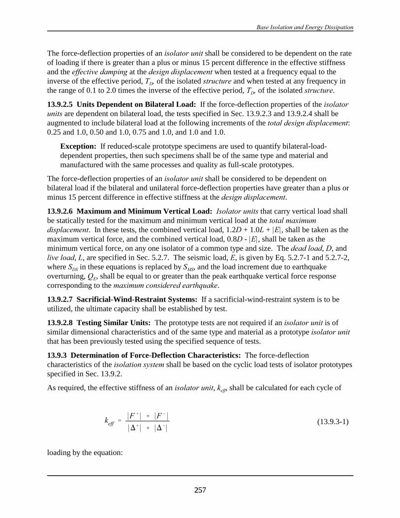
Base Isolation and Energy Dissipation
257257
keff '*F %* % *F &*
*)%* % *)&*(13.9.3-1)
The force-deflection properties of an isolator unit shall be considered to be dependent on the rateof loading if there is greater than a plus or minus 15 percent difference in the effective stiffnessand the effective damping at the design displacement when tested at a frequency equal to theinverse of the effective period, TD, of the isolated structure and when tested at any frequency inthe range of 0.1 to 2.0 times the inverse of the effective period, TD, of the isolated structure.
13.9.2.5 Units Dependent on Bilateral Load: If the force-deflection properties of the isolatorunits are dependent on bilateral load, the tests specified in Sec. 13.9.2.3 and 13.9.2.4 shall beaugmented to include bilateral load at the following increments of the total design displacement:0.25 and 1.0, 0.50 and 1.0, 0.75 and 1.0, and 1.0 and 1.0.
Exception: If reduced-scale prototype specimens are used to quantify bilateral-load-dependent properties, then such specimens shall be of the same type and material andmanufactured with the same processes and quality as full-scale prototypes.
The force-deflection properties of an isolator unit shall be considered to be dependent onbilateral load if the bilateral and unilateral force-deflection properties have greater than a plus orminus 15 percent difference in effective stiffness at the design displacement.
13.9.2.6 Maximum and Minimum Vertical Load: Isolator units that carry vertical load shallbe statically tested for the maximum and minimum vertical load at the total maximumdisplacement. In these tests, the combined vertical load, 1.2D + 1.0L + |E|, shall be taken as themaximum vertical force, and the combined vertical load, 0.8D - |E|, shall be taken as theminimum vertical force, on any one isolator of a common type and size. The dead load, D, andlive load, L, are specified in Sec. 5.2.7. The seismic load, E, is given by Eq. 5.2.7-1 and 5.2.7-2,where SDS in these equations is replaced by SMS, and the load increment due to earthquakeoverturning, QE, shall be equal to or greater than the peak earthquake vertical force responsecorresponding to the maximum considered earthquake.
13.9.2.7 Sacrificial-Wind-Restraint Systems: If a sacrificial-wind-restraint system is to beutilized, the ultimate capacity shall be established by test.
13.9.2.8 Testing Similar Units: The prototype tests are not required if an isolator unit is ofsimilar dimensional characteristics and of the same type and material as a prototype isolator unitthat has been previously tested using the specified sequence of tests.
13.9.3 Determination of Force-Deflection Characteristics: The force-deflectioncharacteristics of the isolation system shall be based on the cyclic load tests of isolator prototypesspecified in Sec. 13.9.2.
As required, the effective stiffness of an isolator unit, keff, shall be calculated for each cycle of
loading by the equation:

2000 Provisions Chapter 13
258258
$eff '2B
Eloop
keff *)%* % *)&* 2 (13.9.3-2)
where F+ and F- are the positive and negative forces at )+ and )-, respectively.
As required, the effective damping, $eff, of an isolator unit shall be calculated for each cycle ofloading by the equation:
where the energy dissipated per cycle of loading, Eloop, and the effective stiffness, keff, shall bebased on peak test displacements of )+ and )-.
13.9.4 Test Specimen Adequacy: The performance of the test specimens shall be assessed asadequate if the following conditions are satisfied:
1. The force-deflection plots of all tests specified in Sec. 13.9.2 have a positive incrementalforce carrying capacity.
1.1. For each increment of test displacement specified in Item 2 of Sec. 13.9.2.3 and foreach vertical load case specified in Sec. 13.9.2.3:
There is no greater than a plus or minus 15 percent difference between the effectivestiffness at each of the three cycles of test and the average value of effective stiffnessfor each test specimen;
1.2. For each increment of test displacement specified in Item 2 of Sec. 13.9.2.3 and foreach vertical load case specified in Sec. 13.9.2.3;
There is no greater than a 15 percent difference in the average value of effectivestiffness of the two test specimens of a common type and size of the isolator unit overthe required three cycles of test;
2. For each specimen there is no greater than a plus or minus 20 percent change in the initialeffective stiffness of each test specimen over the 30SD1BD/SDS, but not less than 10, cycles oftest specified in Item 3 of Sec. 13.9.2.3;
3. For each specimen there is no greater than a 20 percent decrease in the initial effectivedamping over for the 30SD1BD/SDS, but not less than 10, cycles of test specified in Item 3 ofSec. 13.9.2.3; and
4. All specimens of vertical-load-carrying elements of the isolation system remain stable up tothe total maximum displacement for static load as prescribed in Sec. 13.9.2.6 .
13.9.5 Design Properties of the Isolation System:
13.9.5.1 Maximum and Minimum Effective Stiffness: At the design displacement, themaximum and minimum effective stiffness of the isolated system, kDmax and kDmin, shall be basedon the cyclic tests of Item 2 of Sec. 13.9.2.3 and calculated by the equations:
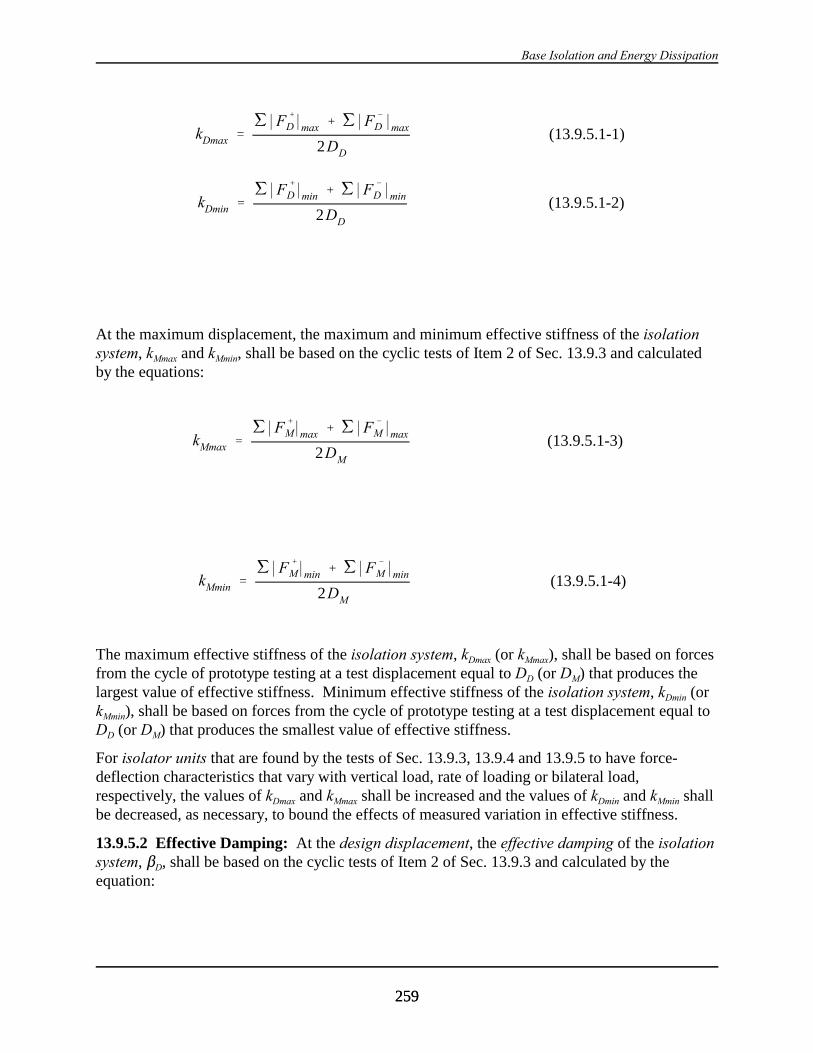
Base Isolation and Energy Dissipation
259259
kDmax ''*F %
D*max % '*F &
D *max
2DD
(13.9.5.1-1)
kDmin ''*F %
D*min % '*F &
D *min
2DD
(13.9.5.1-2)
kMmax ''*F %
M*max % '*F &
M*max
2DM
(13.9.5.1-3)
kMmin ''*F %
M*min % '*F &
M*min
2DM
(13.9.5.1-4)
At the maximum displacement, the maximum and minimum effective stiffness of the isolationsystem, kMmax and kMmin, shall be based on the cyclic tests of Item 2 of Sec. 13.9.3 and calculatedby the equations:
The maximum effective stiffness of the isolation system, kDmax (or kMmax), shall be based on forcesfrom the cycle of prototype testing at a test displacement equal to DD (or DM) that produces thelargest value of effective stiffness. Minimum effective stiffness of the isolation system, kDmin (orkMmin), shall be based on forces from the cycle of prototype testing at a test displacement equal toDD (or DM) that produces the smallest value of effective stiffness.
For isolator units that are found by the tests of Sec. 13.9.3, 13.9.4 and 13.9.5 to have force-deflection characteristics that vary with vertical load, rate of loading or bilateral load,respectively, the values of kDmax and kMmax shall be increased and the values of kDmin and kMmin shallbe decreased, as necessary, to bound the effects of measured variation in effective stiffness.
13.9.5.2 Effective Damping: At the design displacement, the effective damping of the isolationsystem, $D, shall be based on the cyclic tests of Item 2 of Sec. 13.9.3 and calculated by theequation:

2000 Provisions Chapter 13
260260
$D '1
2B
'ED
kDmax D 2D
(13.9.5.2-1)
$M '1
2B
'EM
kMmax D 2M
(13.9.5.2-2)
In Eq. 13.9.5.2-1, the total energy dissipated per cycle of design displacement response, GED,shall be taken as the sum of the energy dissipated per cycle in all isolator units measured at a testdisplacement equal to DD. The total energy dissipated per cycle of design displacement response,GED, shall be based on forces and deflections from the cycle of prototype testing at testdisplacement DD that produces the smallest value of effective damping.
At the maximum displacement, the effective damping of the isolation system, $M, shall be basedon the cyclic tests of Item 2 of Sec. 13.9.3 and calculated by the equation:
In Eq. 13.9.5.2-2, the total energy dissipated per cycle of design displacement response, GEM,shall be taken as the sum of the energy dissipated per cycle in all isolator units measured at a testdisplacement equal to DM. The total energy dissipated per cycle of maximum displacementresponse, GEM, shall be based on forces and deflections from the cycle of prototype testing at testdisplacement DM that produces the smallest value of effective damping.

261261
Appendix to Chapter 13
STRUCTURES WITH DAMPING SYSTEMS
PREFACE: Appendix A13 is an entirely new addition to the 2000 Provisions andcontains design criteria, analysis methods, and testing recommendations that haveno or only limited history of use.
The appendix is intended for the trial use by design professionals, code groups, andregulatory agencies. Design (peer) review is recommended for all structures with adamping system and should be considered essential when this appendix is used as abasis for regulating or approving the design of actual construction.
13A.1 GENERAL: Every structure with a damping system and every portion thereof shall bedesigned and constructed in accordance with the requirements of this appendix and the applicablerequirements of Chapter 1.
Exception: Motion and accelerations of seismically isolated structures which containdamping devices across the plane of isolation shall be determined in accordance with theprovisions of Chapter 13. Testing and strength requirements of damping devices andother elements of the damping system shall be determined in accordance with theapplicable provisions of this Appendix.
13A.2 CRITERIA SELECTION:
13A.2.1 Basis for Design: The procedure and limitations for the design of structures with adamping system shall be determined considering zoning, site characteristics, vertical acceleration,cracked section properties of concrete and masonry members, Seismic Use Group, configuration,structural system, and height in accordance with Sec. 5.2, except as noted below.
13A.2.2 Seismic Use Group: All portions of the structure shall be assigned a Seismic UseGroup in accordance with the requirements of Sec. 1.3.
13A.2.3 Seismic Design Category: Each structure shall be assigned to a Seismic DesignCategory based on the Seismic Use Group and the design spectral response acceleration inaccordance with Sec. 4.2.
Exception: Seismic Design Category A structures with a damping system shall bedesigned using the design spectral response acceleration determined in accordance withSec. 4.1.2.5 and the analysis methods and design provisions required for Seismic DesignCategory B structures.
13A.2.4 Configuration Requirements: Structure design shall consider the combination offorces that occur in the basic seismic-force-resisting system and the damping system, as definedin the following sections.
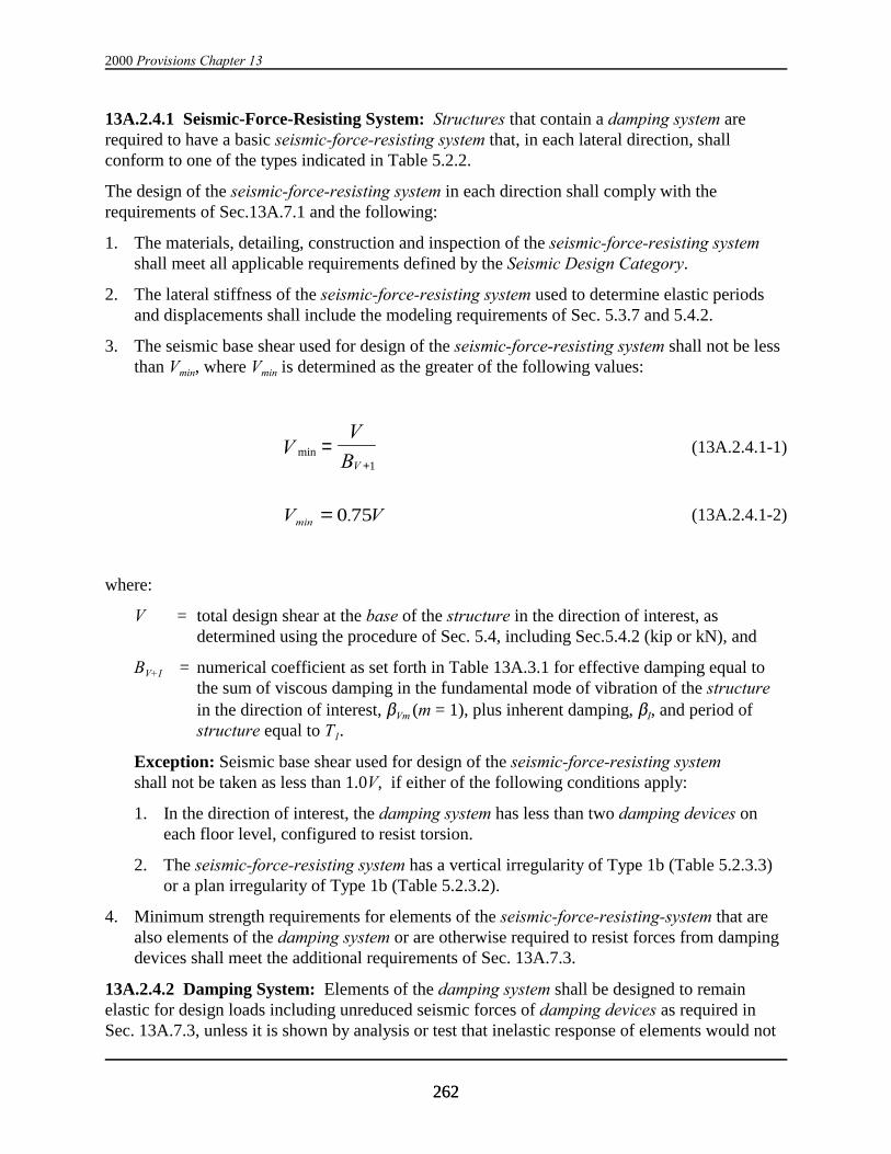
2000 Provisions Chapter 13
262262
13A.2.4.1 Seismic-Force-Resisting System: Structures that contain a damping system arerequired to have a basic seismic-force-resisting system that, in each lateral direction, shallconform to one of the types indicated in Table 5.2.2.
The design of the seismic-force-resisting system in each direction shall comply with therequirements of Sec.13A.7.1 and the following:
1. The materials, detailing, construction and inspection of the seismic-force-resisting systemshall meet all applicable requirements defined by the Seismic Design Category.
2. The lateral stiffness of the seismic-force-resisting system used to determine elastic periodsand displacements shall include the modeling requirements of Sec. 5.3.7 and 5.4.2.
3. The seismic base shear used for design of the seismic-force-resisting system shall not be lessthan Vmin, where Vmin is determined as the greater of the following values:
(13A.2.4.1-1)minVV
BV
=+1
(13A.2.4.1-2)V Vmin .= 0 75
where:
V = total design shear at the base of the structure in the direction of interest, asdetermined using the procedure of Sec. 5.4, including Sec.5.4.2 (kip or kN), and
BV+I = numerical coefficient as set forth in Table 13A.3.1 for effective damping equal tothe sum of viscous damping in the fundamental mode of vibration of the structurein the direction of interest, $Vm (m = 1), plus inherent damping, $I, and period ofstructure equal to T1.
Exception: Seismic base shear used for design of the seismic-force-resisting systemshall not be taken as less than 1.0V, if either of the following conditions apply:
1. In the direction of interest, the damping system has less than two damping devices oneach floor level, configured to resist torsion.
2. The seismic-force-resisting system has a vertical irregularity of Type 1b (Table 5.2.3.3)or a plan irregularity of Type 1b (Table 5.2.3.2).
4. Minimum strength requirements for elements of the seismic-force-resisting-system that arealso elements of the damping system or are otherwise required to resist forces from dampingdevices shall meet the additional requirements of Sec. 13A.7.3.
13A.2.4.2 Damping System: Elements of the damping system shall be designed to remainelastic for design loads including unreduced seismic forces of damping devices as required inSec. 13A.7.3, unless it is shown by analysis or test that inelastic response of elements would not
Base Isolation and Energy Dissipation
263263
adversely affect damping system function and inelastic response is limited in accordance with therequirements of Sec. 13A.7.3.4.
13A.2.5 Seismic Criteria:
13A.2.5.1 Design Spectra: Spectra of the design earthquake and the maximum consideredearthquake developed in accordance with Sec. 13.4.4.1 shall be used for the design and analysisof all structures with a damping system. Site-specific design spectra shall be developed and usedfor design of structures with a damping system if any one of the following conditions apply:
1. The structure is located on a Class F site or
2. The structure is located at a site with S1 greater than 0.60.
13A.2.5.2 Time Histories: Ground-motion time histories of the design earthquake and themaximum considered earthquake developed in accordance with Sec. 13.4.4.2 shall be used fordesign and analysis of all structures with a damping system if either of the following conditionsapply:
1. The structure is located at a site with S1 greater than 0.60.
2. The damping system is explicitly modeled and analyzed using the time history analysismethod.
13A.2.6 Selection of Analysis Procedure:
13A.2.6.1 General: A structural analysis shall be made for all structures with a damping systemin accordance with the requirements of this section. The structural analysis shall use linearprocedures, nonlinear procedures, or a combination of linear and nonlinear procedures asdescribed below.
The seismic-force-resisting system shall be designed using the procedures of either Sec.13A.2.6.2 or Sec. 13A.2.6.3.
The damping system may be designed using the procedures of either Sec. 13A.2.6.2 or 13A.2.6.3,subject to the limitations set forth in these sections. Damping systems not meeting theselimitations shall be designed using the nonlinear analysis methods as required in Sec. 13A.6.
13A.2.6.2 Equivalent Lateral Force Analysis Procedure: Structures with a damping systemdesigned using the equivalent lateral force analysis procedure of Sec. 13A.4 shall be subject tothe following limitations:
1. In the direction of interest, the damping system has at least two damping devices in eachstory, configured to resist torsion.
2. The total effective damping of the fundamental mode, βmD (m = 1), of the structure in thedirection of interest is not greater than 35 percent of critical.
3. The seismic-force-resisting system does not have a vertical irregularity of Type 1a, 1b, 2, or 3(Table 5.2.3.3) or a plan irregularity of Type 1a or 1b (Table 5.2.3.2).
4. Floor diaphragms are rigid (Sec. 5.2.31).
2000 Provisions Chapter 13
264264
5. The height of the structure above the base does not exceed 100 ft (30 m).
6. Peak dynamic response of the structure and elements of the damping system are confirmedby nonlinear time history analysis, when required by Sec. 13A.2.6.4.3.
13A.2.6.3 Response Spectrum Analysis: Structures with a damping system meeting thelimitations of Sec. 13A.2.6.2 may be designed using the response spectrum analysis procedure ofSec. 13A.5 and structures not meeting the limitations of Sec. 13A.2.6.2 shall be designed usingthe response spectrum analysis procedure of Sec. 13A.5, subject to the following limitations:
1. In the direction of interest, the damping system has at least two damping devices in eachstory, configured to resist torsion,
2. The total effective damping of the fundamental mode, βmD (m = 1), of the structure in thedirection of interest is not greater than 35 percent of critical, and
3. Peak dynamic response of the structure and elements of the damping system are confirmedby nonlinear time history analysis, when required by Sec. 13A.2.6.4.3.
13A.2.6.4 Nonlinear Analysis:
13A.2.6.4.1 General: Nonlinear analysis procedures of Sec.13A.6 are permitted for design ofall structures with damping systems and shall be used for design of structures with dampingsystems not meeting linear analysis criteria of Sec. 13A.2.6.3.
Nonlinear time history analysis shall be used to confirm peak dynamic response of the structureand elements of the damping system if the structure is located at a site with S1 greater than 0.60g.
The nonlinear force-deflection characteristics of elements of the seismic-force-resisting systemshall be modeled as required by Sec. 5.7.1 and 5.8.1. The nonlinear force-deflectioncharacteristics of damping devices shall be modeled, as required, to explicitly account for devicedependence on frequency, amplitude and duration of seismic loading.
13A.2.6.4.2 Nonlinear Static Analysis: Structures with a damping system designed using thenonlinear static analysis procedure of Sec. 13A.6 shall be subject to the following limitations:
1. Peak dynamic response of the structure and elements of the damping system is confirmed bynonlinear time history analysis, when required by Sec. 13A.2.6.4.3.
13A.2.6.4.3 Nonlinear Time History Analysis: Structures with a damping system may bedesigned using the nonlinear time history analysis procedure of Sec. 13A.6 without limitation.
Nonlinear time history analysis shall be used to confirm peak dynamic response of the structureand elements of the damping system for structures with a damping system if the followingconditions applies:
1. The structure is located at site with S1 greater than 0.60.
13A.3 DAMPED RESPONSE MODIFICATION:
13A.3.1 General: As required in Sec. 13A.4 and 13A.5, response of the structure shall bemodified for the effects of the damping system using coefficients prescribed in Table 13A.3.1.
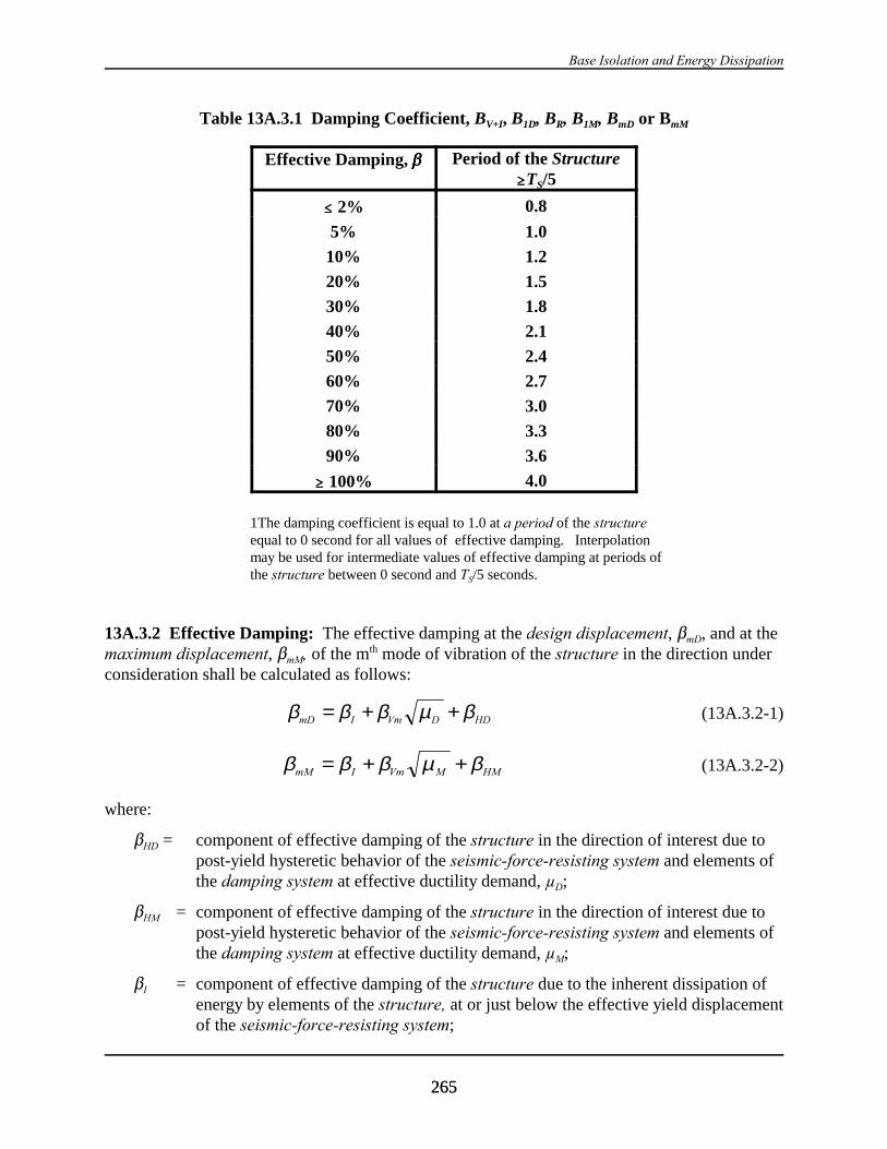
Base Isolation and Energy Dissipation
265265
Table 13A.3.1 Damping Coefficient, BV+I, B1D, BR, B1M, BmD or BmM
Effective Damping, ββββ Period of the Structure$$$$TS/5
#### 2% 0.8
5% 1.0
10% 1.2
20% 1.5
30% 1.8
40% 2.1
50% 2.4
60% 2.7
70% 3.0
80% 3.3
90% 3.6
$$$$ 100% 4.0
1The damping coefficient is equal to 1.0 at a period of the structureequal to 0 second for all values of effective damping. Interpolationmay be used for intermediate values of effective damping at periods ofthe structure between 0 second and TS/5 seconds.
13A.3.2 Effective Damping: The effective damping at the design displacement, $mD, and at themaximum displacement, $mM, of the mth mode of vibration of the structure in the direction underconsideration shall be calculated as follows:
(13A.3.2-1)β β β µ βmD I Vm D HD= + +
(13A.3.2-2)β β β µ βmM I Vm M HM= + +
where:
$HD = component of effective damping of the structure in the direction of interest due topost-yield hysteretic behavior of the seismic-force-resisting system and elements ofthe damping system at effective ductility demand, µD;
$HM = component of effective damping of the structure in the direction of interest due topost-yield hysteretic behavior of the seismic-force-resisting system and elements ofthe damping system at effective ductility demand, µM;
$I = component of effective damping of the structure due to the inherent dissipation ofenergy by elements of the structure, at or just below the effective yield displacementof the seismic-force-resisting system;

2000 Provisions Chapter 13
266266
$Vm = component of effective damping of the mth mode of vibration of the structure in thedirection of interest due to viscous dissipation of energy by the damping system, ator just below the effective yield displacement of the seismic-force-resisting system;
µD = effective ductility demand on the seismic-force-resisting system in the direction ofinterest due to the design earthquake; and
µM = effective ductility demand on the seismic-force-resisting system in the direction ofinterest due to the maximum considered earthquake.
Unless analysis or test data supports other values, the effective ductility demand of higher modesof vibration in the direction of interest shall be taken as 1.0.
13A.3.2.1 Inherent Damping: Inherent damping, $I, shall be based on the material type,configuration and behavior of the structure and nonstructural components respondingdynamically at or just below yield of the seismic-force-resisting system. Unless analysis or testdata supports other values, inherent damping shall be taken as not greater than 5 percent ofcritical for all modes of vibration.
13A.3.2.2 Hysteretic Damping: Hysteretic damping of the seismic-force-resisting system andelements of the damping system shall be based either on test or analysis, or in accordance withthe following equations:
(13A.3.2.2-1)( )β βµHD H I
D
q= − −
0 64 1
1.
(13A.3.2.2-2)( )β βµHM H I
M
q= − −
0 64 1
1.
where:
qH = hysteresis loop adjustment factor, as defined in Sec. 13A.3.3;
µD = effective ductility demand on the seismic-force-resisting system in the direction ofinterest due to the design earthquake, as defined in Sec. A.13.3.4; and
µM = effective ductility demand on the seismic-force-resisting system in the direction ofinterest due to the maximum considered earthquake, as defined in Sec. 13A.3.4.
Unless analysis or test data supports other values, the hysteretic damping of higher modes ofvibration in the direction of interest shall be taken as zero.
13A.3.2.3 Viscous Damping: Viscous damping of the mth mode of vibration of the structure,$Vm, shall be calculated as follows:
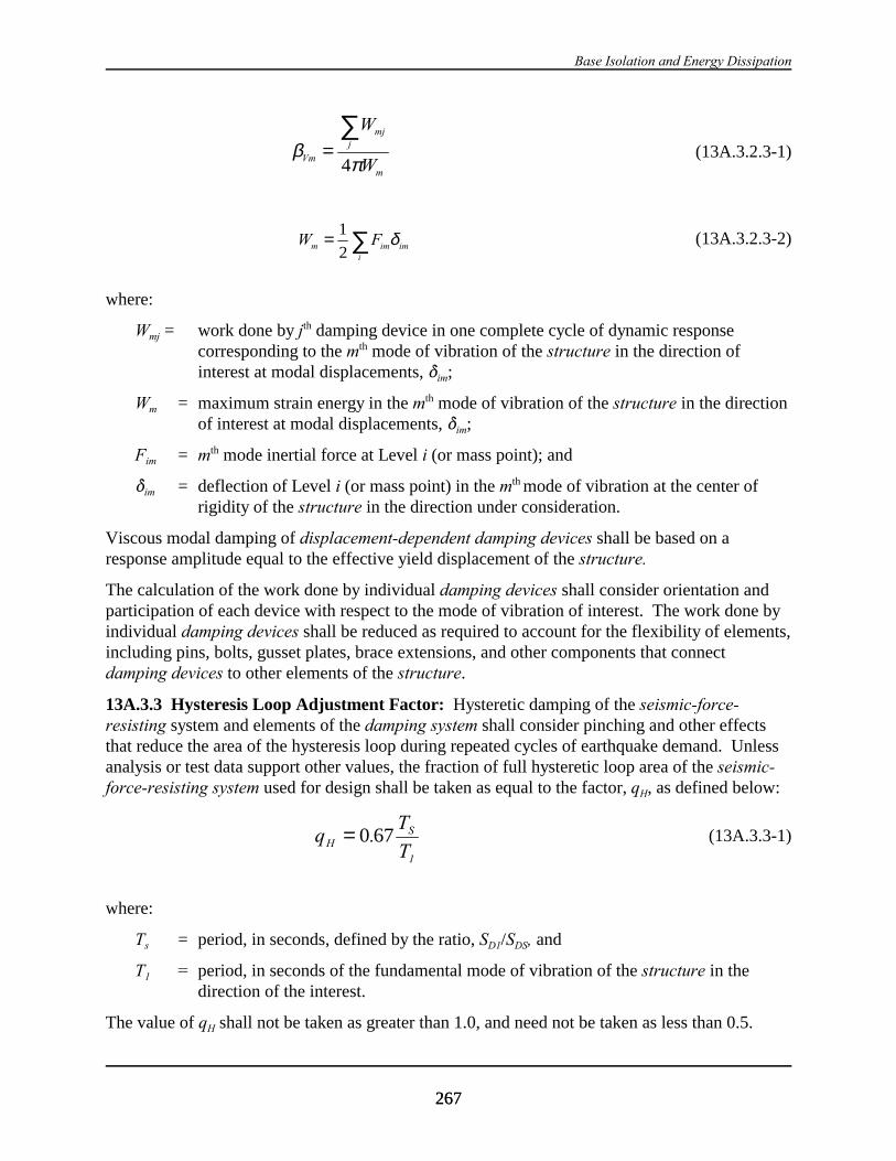
Base Isolation and Energy Dissipation
267267
(13A.3.2.3-1)βπVm
mjj
m
W
W=
∑4
(13A.3.2.3-2)W Fm im imi
= ∑1
2δ
where:
Wmj = work done by jth damping device in one complete cycle of dynamic responsecorresponding to the mth mode of vibration of the structure in the direction ofinterest at modal displacements, *im;
Wm = maximum strain energy in the mth mode of vibration of the structure in the directionof interest at modal displacements, *im;
Fim = mth mode inertial force at Level i (or mass point); and
*im = deflection of Level i (or mass point) in the mth mode of vibration at the center ofrigidity of the structure in the direction under consideration.
Viscous modal damping of displacement-dependent damping devices shall be based on aresponse amplitude equal to the effective yield displacement of the structure.
The calculation of the work done by individual damping devices shall consider orientation andparticipation of each device with respect to the mode of vibration of interest. The work done byindividual damping devices shall be reduced as required to account for the flexibility of elements,including pins, bolts, gusset plates, brace extensions, and other components that connectdamping devices to other elements of the structure.
13A.3.3 Hysteresis Loop Adjustment Factor: Hysteretic damping of the seismic-force-resisting system and elements of the damping system shall consider pinching and other effectsthat reduce the area of the hysteresis loop during repeated cycles of earthquake demand. Unlessanalysis or test data support other values, the fraction of full hysteretic loop area of the seismic-force-resisting system used for design shall be taken as equal to the factor, qH, as defined below:
(13A.3.3-1)qT
THS= 0 67.1
where:
Ts = period, in seconds, defined by the ratio, SD1/SDS, and
T1 = period, in seconds of the fundamental mode of vibration of the structure in thedirection of the interest.
The value of qH shall not be taken as greater than 1.0, and need not be taken as less than 0.5.
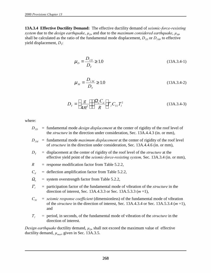
2000 Provisions Chapter 13
268268
13A.3.4 Effective Ductility Demand: The effective ductility demand of seismic-force-resistingsystem due to the design earthquake, µD, and due to the maximum considered earthquake, µM,shall be calculated as the ratio of the fundamental mode displacement, D1D or D1M, to effectiveyield displacement, DY:
(13A.3.4-1)µDD
Y
D
D= ≥1 10.
(13A.3.4-2)µMMD= ≥1
YD10.
(13A.3.4-3)Dg C
RC TY
o dS=
4 2
2
πΩ Γ1 1 1
where:
D1D = fundamental mode design displacement at the center of rigidity of the roof level ofthe structure in the direction under consideration, Sec. 13A.4.4.3 (in. or mm),
D1M = fundamental mode maximum displacement at the center of rigidity of the roof levelof structure in the direction under consideration, Sec. 13A.4.4.6 (in. or mm),
DY = displacement at the center of rigidity of the roof level of the structure at theeffective yield point of the seismic-force-resisting system, Sec. 13A.3.4 (in. or mm),
R = response modification factor from Table 5.2.2,
Cd = deflection amplification factor from Table 5.2.2,
So = system overstrength factor from Table 5.2.2,
'1 = participation factor of the fundamental mode of vibration of the structure in thedirection of interest, Sec. 13A.4.3.3 or Sec. 13A.5.3.3 (m =1),
CS1 = seismic response coefficient (dimensionless) of the fundamental mode of vibrationof the structure in the direction of interest, Sec. 13A.4.3.4 or Sec. 13A.5.3.4 (m =1),and
T1 = period, in seconds, of the fundamental mode of vibration of the structure in thedirection of interest.
Design earthquake ductility demand, µD, shall not exceed the maximum value of effectiveductility demand, µmax, given in Sec. 13A.3.5.

Base Isolation and Energy Dissipation
269269
13A.3.5 Maximum Effective Ductility Demand: For determination of the hysteresis loopadjustment factor, hysteretic damping and other parameters, ductility demand used for design ofthe structure shall not exceed the maximum value of effective ductility demand, µmax, as definedbelow:
For T1D < TS : (13A.3.5-1)µmax =
+
1
21
2
R
IoΩ
For T1 $ TS : (13A.3.5-2)µmax = R
IoΩ
where:
I = the occupancy importance factor determined in accordance with Sec. 1.4.
T1D = effective period, in seconds, of the fundamental mode of vibration of the structureat the design displacement in the direction under consideration.
For periods: T1 # TS # T1D, interpolation shall be used to determine µmax.
13A.4 EQUIVALENT LATERAL FORCE ANALYSIS PROCEDURE:
13A.4.1 General: This section provides required minimum standards for equivalent lateralforce analysis of structures with a damping system. For purposes of analysis, the structure isconsidered to be fixed at the base. See Sec. 13A.2.6 for limitations on the use of this procedure.
Seismic base shear and lateral forces at floors used for design of the seismic-force-resistingsystem shall be based on the procedures of Sec. 13A.4.3. Seismic forces, displacements andvelocities used for design of the damping system shall be based on the procedures of Sec.13A.4.4.
The load combinations and acceptance criteria of Sec. 13A.7 shall be used to check designresponses of seismic-force-resisting and damping systems, respectively.
13A.4.2 Modeling Requirements: Elements of the seismic-force-resisting system shall bemodeled in a manner consistent with the requirements of Sec. 5.4.
Elements of the damping system shall be modeled as required to determine design forcestransferred from damping devices to both the ground and the seismic-force-resisting system. Theeffective stiffness of velocity-dependent damping devices shall be modeled.
Damping devices need not be explicitly modeled provided effective damping is calculated inaccordance with the procedures of Sec. 13A.3 and used to modify response as required in Sec.13A.4.3 and 13A.4.4.
The stiffness and damping properties of the damping devices used in the models shall be basedon or verified by testing of the damping devices as specified in Sec. 13A.10.

2000 Provisions Chapter 13
270270
13A.4.3 Seismic-Force-Resisting-System Design Response:
13A.4.3.1 Seismic Base Shear: The seismic base shear, V, of the seismic-force-resistingsystem in a given direction shall be determined as the combination of the two modal components,V1 and VR, in accordance with the following equation:
(13A.4.3.1-1)V V V VR= + ≥12 2
min
where:
V1 = design value of the seismic base shear of the fundamental mode in a given directionof response (kip or kN),
VR = design value of the seismic base shear of the residual mode in a given direction (kipor kN), and
Vmin = minimum allowable value of base shear permitted for design of the seismic-force-resisting-system of the structure in direction of the interest (kip or kN).
13A.4.3.2 Fundamental Mode Base Shear: Fundamental mode base shear, V1, shall bedetermined in accordance with the following equation:
(13A.4.3.2-1)V C WS1 1 1=
where:
= the effective fundamental mode gravity load including portions of the live load asW1
defined by Eq. 5.5.5-2 for m = 1 (kip or kN).
13A.4.3.3 Fundamental Mode Properties: Fundamental mode shape, Ni1, and participationfactor, '1, shall be determined by either dynamic analysis of elastic structural properties anddeformational characteristics of the resisting elements or in accordance with the followingequations:
(13A.4.3.3-1)φii
r
h
h1 =
(13A.4.3.3-2)Γ11
1i=
=∑
W
wi i
n
φ1
where:
hi = the height of the structure above the base to Level i (ft or m),
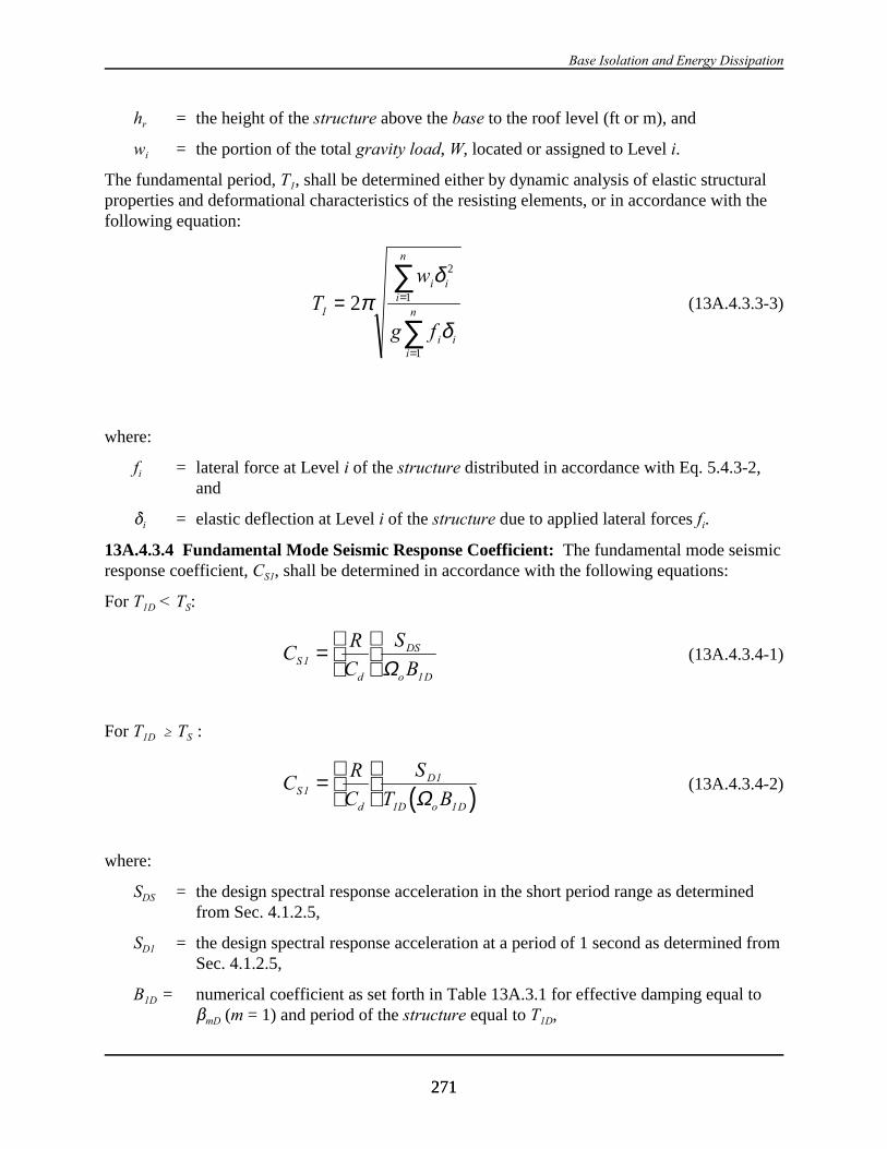
Base Isolation and Energy Dissipation
271271
hr = the height of the structure above the base to the roof level (ft or m), and
wi = the portion of the total gravity load, W, located or assigned to Level i.
The fundamental period, T1, shall be determined either by dynamic analysis of elastic structuralproperties and deformational characteristics of the resisting elements, or in accordance with thefollowing equation:
(13A.4.3.3-3)Tw
g f
i ii
n
i ii
n1 = =
=
∑
∑2
2
1
1
πδ
δ
where:
fi = lateral force at Level i of the structure distributed in accordance with Eq. 5.4.3-2,and
*i = elastic deflection at Level i of the structure due to applied lateral forces fi.
13A.4.3.4 Fundamental Mode Seismic Response Coefficient: The fundamental mode seismicresponse coefficient, CS1, shall be determined in accordance with the following equations:
For T1D < TS:
(13A.4.3.4-1)CR
C
S
BS
d
DS
o D
1
1
=
Ω
For T1D $ TS :
(13A.4.3.4-2)( )CR
C
S
BS
d
D
o D
11
1D 1T=
Ω
where:
SDS = the design spectral response acceleration in the short period range as determinedfrom Sec. 4.1.2.5,
SD1 = the design spectral response acceleration at a period of 1 second as determined fromSec. 4.1.2.5,
B1D = numerical coefficient as set forth in Table 13A.3.1 for effective damping equal to$mD (m = 1) and period of the structure equal to T1D,

2000 Provisions Chapter 13
272272
13A.4.3.5 Effective Fundamental Mode Period Determination: The effective fundamentalmode period at the design earthquake, T1D, and at the maximum considered earthquake, T1M, shallbe based either on explicit consideration of the post-yield force deflection characteristics of thestructure or in accordance with the following equations:
(13A.4.3.5-1)T TD D1 1= µ
(13A.4.3.5-2)T TM M1 1= µ
where:
T1M = effective period, in seconds, of the fundamental mode of vibration of the structureat the maximum displacement in the direction under consideration.
13A.4.3.6 Residual Mode Base Shear: Residual mode base shear, VR, shall be determined inaccordance with the following equation:
(13A.4.3.6-1)V C WR SR R=
where:
CSR = the residual mode seismic response coefficient as determined in Sec. 13A.4.3.8, and
= the effective residual mode gravity load of the structure determined in accordanceWR
with Eq. 13A.4.3.7-3 (kip or kN).
13A.4.3.7 Residual Mode Properties: Residual mode shape, NiR, participation factor, ΓR,
effective gravity load of the structure, , and effective period, TR, shall be determined inWR
accordance with the following equations:
(13A.4.3.7-1)φ φiR
i= −−
1
1
ΓΓ1 1
1
(13A.4.3.7-2)Γ ΓR = −1 1
(13A.4.3.7-3)W W WR = − 1
(13A.4.3.7-4)T TR = 0 4. 1
13A.4.3.8 Residual Mode Seismic Response Coefficient: The residual mode seismic responsecoefficient, CSR, shall be determined in accordance with the following equation:
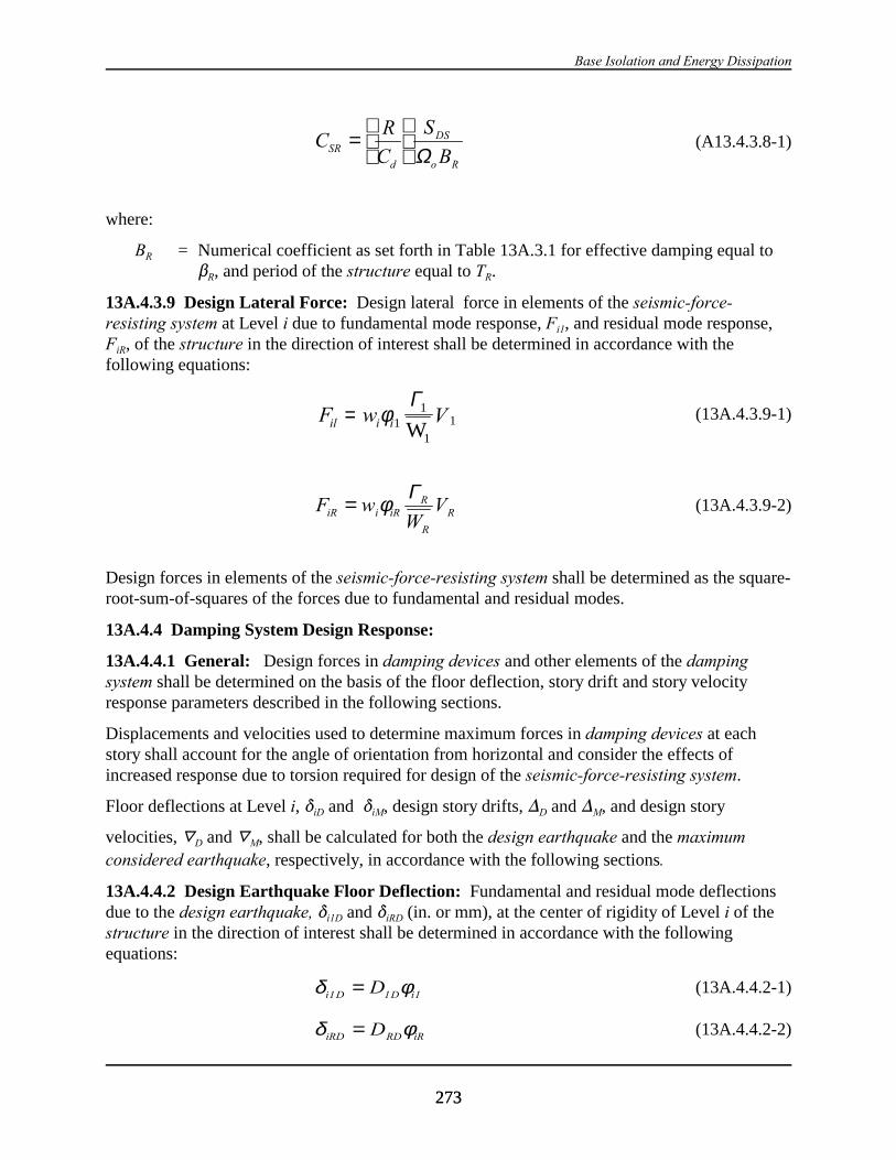
Base Isolation and Energy Dissipation
273273
(A13.4.3.8-1)CR
C
S
BSR
d
DS
o R
=
Ω
where:
BR = Numerical coefficient as set forth in Table 13A.3.1 for effective damping equal to$R, and period of the structure equal to TR.
13A.4.3.9 Design Lateral Force: Design lateral force in elements of the seismic-force-resisting system at Level i due to fundamental mode response, Fi1, and residual mode response,FiR, of the structure in the direction of interest shall be determined in accordance with thefollowing equations:
(13A.4.3.9-1)F w Vil i i= φ11
1W
Γ1
(13A.4.3.9-2)F wW
ViR i iRR
R
R= φ Γ
Design forces in elements of the seismic-force-resisting system shall be determined as the square-root-sum-of-squares of the forces due to fundamental and residual modes.
13A.4.4 Damping System Design Response:
13A.4.4.1 General: Design forces in damping devices and other elements of the dampingsystem shall be determined on the basis of the floor deflection, story drift and story velocityresponse parameters described in the following sections.
Displacements and velocities used to determine maximum forces in damping devices at eachstory shall account for the angle of orientation from horizontal and consider the effects ofincreased response due to torsion required for design of the seismic-force-resisting system.
Floor deflections at Level i, *iD and *iM, design story drifts, )D and )M, and design story
velocities, «D and «M, shall be calculated for both the design earthquake and the maximumconsidered earthquake, respectively, in accordance with the following sections.
13A.4.4.2 Design Earthquake Floor Deflection: Fundamental and residual mode deflectionsdue to the design earthquake, *i1D and *iRD (in. or mm), at the center of rigidity of Level i of thestructure in the direction of interest shall be determined in accordance with the followingequations:
(13A.4.4.2-1)δ φi D D iD1 1 1=
(13A.4.4.2-2)δ φiRD RD iRD=

2000 Provisions Chapter 13
274274
where:
DRD = Residual mode design displacement at the center of rigidity of the roof level of thestructure in the direction under consideration, Sec. 13A.4.4.3 (in. or mm).
The total design earthquake deflection at each floor of the structure in the direction of interestshall be calculated as the square-root-sum-of-squares of fundamental and residual mode floordeflections.
13A.4.4.3 Design Earthquake Roof Displacement: Fundamental and residual modedisplacements due to the design earthquake, D1D and D1R (in.or mm) at the center of rigidity ofthe roof level of the structure in the direction of interest shall be determined in accordance withthe following equations:
(13A.4.4.3-1)Dg S T g S T
BDD D DS D
D
1 11 1
1D
1
1B=
≤
4 42 2 1
2
π πΓ Γ
(13A.4.4.3-2)Dg S T g S T
BRD RD R
RDS R
R
=
≤
4 42 2
2
π πΓ Γ1
RB
13A.4.4.4 Design Earthquake Story Drift: Design earthquake story drift, )D, of the structurein the direction of interest shall be calculated in accordance with the following equation:
(13A.4.4.4-1)∆ ∆ ∆D D= +1 RD2 2
where:
)1D = design earthquake story drift due to the fundamental mode of vibration of thestructure in the direction of interest (in. or mm) and
)RD = design earthquake story drift due to the residual mode of vibration of the structurein the direction of interest (in. or mm).
Modal design earthquake story drifts, ∆1D and ∆1R, shall be determined in accordance with Sec.5.3.7.1 using the floor deflections of Sec. 13A.4.4.2.
13A.4.4.5 Design Earthquake Story Velocity: Design earthquake story velocity, VD, of thestructure in the direction of interest shall be calculated in accordance with the followingequations:
(13A.4.4.5-1)∇ ∇ ∇D D RD= +12 2
(13A.4.4.5-2)∇ 11
1
DD
DT= 2π ∆
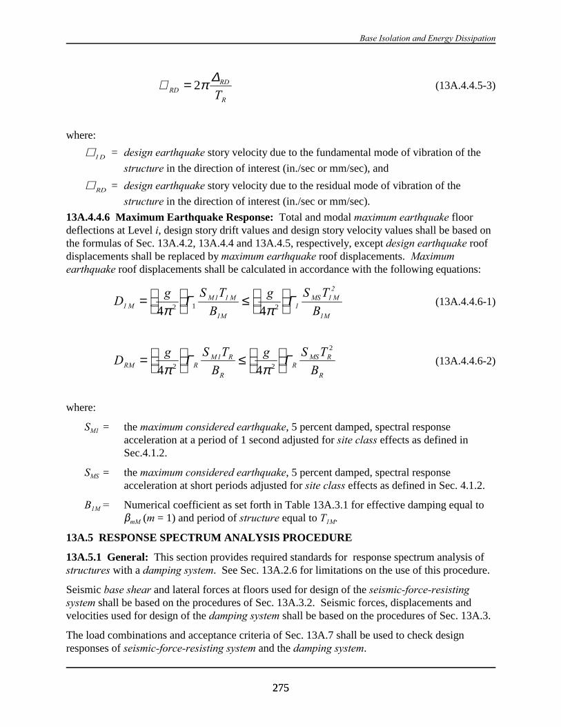
Base Isolation and Energy Dissipation
275275
(13A.4.4.5-3)∇ RDRD
RT= 2π ∆
where:
= design earthquake story velocity due to the fundamental mode of vibration of the∇ 1D
structure in the direction of interest (in./sec or mm/sec), and
= design earthquake story velocity due to the residual mode of vibration of the∇ RD
structure in the direction of interest (in./sec or mm/sec).
13A.4.4.6 Maximum Earthquake Response: Total and modal maximum earthquake floordeflections at Level i, design story drift values and design story velocity values shall be based onthe formulas of Sec. 13A.4.2, 13A.4.4 and 13A.4.5, respectively, except design earthquake roofdisplacements shall be replaced by maximum earthquake roof displacements. Maximumearthquake roof displacements shall be calculated in accordance with the following equations:
(13A.4.4.6-1)Dg S T g S T
MM M MS M
11 1
1M
112
1MB B=
≤
4 42 1 2π π
Γ Γ
(13A.4.4.6-2)Dg S T
B
g S T
BRM RM R
R
RMS R
R
=
≤
4 42 2
2
π πΓ Γ1
where:
SM1 = the maximum considered earthquake, 5 percent damped, spectral responseacceleration at a period of 1 second adjusted for site class effects as defined inSec.4.1.2.
SMS = the maximum considered earthquake, 5 percent damped, spectral responseacceleration at short periods adjusted for site class effects as defined in Sec. 4.1.2.
B1M = Numerical coefficient as set forth in Table 13A.3.1 for effective damping equal to$mM (m = 1) and period of structure equal to T1M.
13A.5 RESPONSE SPECTRUM ANALYSIS PROCEDURE
13A.5.1 General: This section provides required standards for response spectrum analysis ofstructures with a damping system. See Sec. 13A.2.6 for limitations on the use of this procedure.
Seismic base shear and lateral forces at floors used for design of the seismic-force-resistingsystem shall be based on the procedures of Sec. 13A.3.2. Seismic forces, displacements andvelocities used for design of the damping system shall be based on the procedures of Sec. 13A.3.
The load combinations and acceptance criteria of Sec. 13A.7 shall be used to check designresponses of seismic-force-resisting system and the damping system.
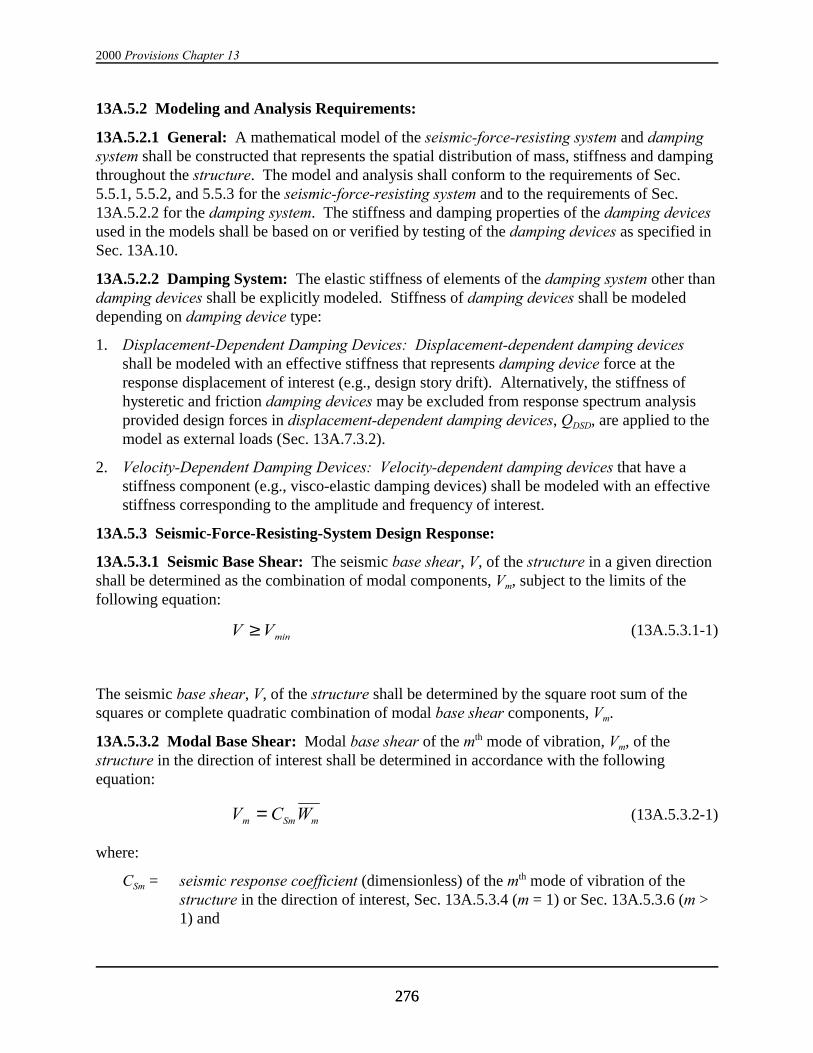
2000 Provisions Chapter 13
276276
13A.5.2 Modeling and Analysis Requirements:
13A.5.2.1 General: A mathematical model of the seismic-force-resisting system and dampingsystem shall be constructed that represents the spatial distribution of mass, stiffness and dampingthroughout the structure. The model and analysis shall conform to the requirements of Sec.5.5.1, 5.5.2, and 5.5.3 for the seismic-force-resisting system and to the requirements of Sec.13A.5.2.2 for the damping system. The stiffness and damping properties of the damping devicesused in the models shall be based on or verified by testing of the damping devices as specified inSec. 13A.10.
13A.5.2.2 Damping System: The elastic stiffness of elements of the damping system other thandamping devices shall be explicitly modeled. Stiffness of damping devices shall be modeleddepending on damping device type:
1. Displacement-Dependent Damping Devices: Displacement-dependent damping devicesshall be modeled with an effective stiffness that represents damping device force at theresponse displacement of interest (e.g., design story drift). Alternatively, the stiffness ofhysteretic and friction damping devices may be excluded from response spectrum analysisprovided design forces in displacement-dependent damping devices, QDSD, are applied to themodel as external loads (Sec. 13A.7.3.2).
2. Velocity-Dependent Damping Devices: Velocity-dependent damping devices that have astiffness component (e.g., visco-elastic damping devices) shall be modeled with an effectivestiffness corresponding to the amplitude and frequency of interest.
13A.5.3 Seismic-Force-Resisting-System Design Response:
13A.5.3.1 Seismic Base Shear: The seismic base shear, V, of the structure in a given directionshall be determined as the combination of modal components, Vm, subject to the limits of thefollowing equation:
(13A.5.3.1-1)V V≥ min
The seismic base shear, V, of the structure shall be determined by the square root sum of thesquares or complete quadratic combination of modal base shear components, Vm.
13A.5.3.2 Modal Base Shear: Modal base shear of the mth mode of vibration, Vm, of thestructure in the direction of interest shall be determined in accordance with the followingequation:
(13A.5.3.2-1)V C Wm Sm m=
where:
CSm = seismic response coefficient (dimensionless) of the mth mode of vibration of thestructure in the direction of interest, Sec. 13A.5.3.4 (m = 1) or Sec. 13A.5.3.6 (m >1) and

Base Isolation and Energy Dissipation
277277
= the effective gravity load of the mth mode of vibration of the structure determined inWm
accordance with Eq. 5.4.4-2 (kip or kN).
13A.5.3.3 Modal Participation Factor: The modal participation factor of the mth mode ofvibration, 'm, of the structure in the direction of interest shall be determined in accordance withthe following equation:
(13A.5.3.3-1)Γmm
i imi
n
W
w=
=∑ φ
1
where:
= displacement amplitude at the ith level of the structure for the fixed base conditionφim
in the mth mode of vibration in the direction of interest, normalized to unity at theroof level.
13A.5.3.4 Fundamental Mode Seismic Response Coefficient: The fundamental mode (m = 1)seismic response coefficient, CS1, in the direction of interest shall be determined in accordancewith the following equations:
For T1D < TS : (13A.5.3.4-1)CR
C
S
BS
d
DS
o D
1
1
=
Ω
For T1D $ TS : (13A.5.3.4-2)( )CR
C
S
BS
d
D
o D
11
1D 1T=
Ω
13A.5.3.5 Effective Fundamental Mode Period Determination: The effective fundamentalmode (m = 1) period at the design earthquake, T1D, and at the maximum considered earthquake,T1M, shall be based either on explicit consideration of the post-yield nonlinear force deflectioncharacteristics of the structure or determined in accordance with the following equations:
(13A.4.3.5-1)T TD D1 1= µ
(13A.4.3.5-2)T TM M1 1= µ
13A.5.3.6 Higher Mode Seismic Response Coefficient: Higher mode (m > 1) seismicresponse coefficient, CSm, of the mth mode of vibration (m > 1) of the structure in the direction ofinterest shall be determined in accordance with the following equations:

2000 Provisions Chapter 13
278278
For Tm < TS : (13A.5.3.6-1)CR
C
S
BSm
d
DS
o mD
=
Ω
For Tm $ TS : (13A.5.3.6-2)( )CR
C
S
BSm
d
D
o mD
=
1
mT Ω
where:
Tm = period, in seconds, of the mth mode of vibration of the structure in the directionunder consideration and
BmD = numerical coefficient as set forth in Table 13A.3.1 for effective damping equal to$mD and period of the structure equal to Tm.
13A.5.3.7 Design Lateral Force: Design lateral force at Level i due to mth mode of vibration,Fim, of the structure in the direction of interest shall be determined in accordance with thefollowing equation:
(13A.5.3.7-1)F wW
Vim i imm
m
m= φ Γ
Design forces in elements of the seismic-force-resisting system shall be determined by the squareroot sum of squares or complete quadratic combination of modal design forces.
13A.5.4 Damping System Design Response:
13A.5.4.1 General: Design forces in damping devices and other elements of the dampingsystem shall be determined on the basis of the floor deflection, story drift and story velocityresponse parameters described in the following sections.
Displacements and velocities used to determine maximum forces in damping devices at eachstory shall account for the angle of orientation from horizontal and consider the effects ofincreased response due to torsion required for design of the seismic-force-resisting system.
Floor deflections at Level i, *iD and *iM, design story drifts, )D and )M, and design storyvelocities, LD and LM, shall be calculated for both the design earthquake and the maximumconsidered earthquake, respectively, in accordance with the following sections.
13A.5.4.2 Design Earthquake Floor Deflection: The deflection of structure due to the designearthquake at Level i in the mth mode of vibration, *imD (in. or mm), of the structure in thedirection of interest shall be determined in accordance with the following equation:
(13A.5.4.2-1)δ φimD mD imD=
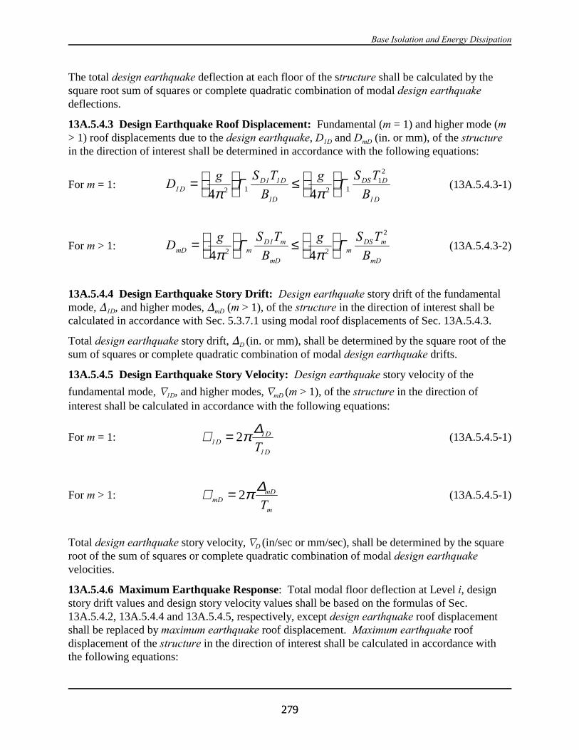
Base Isolation and Energy Dissipation
279279
The total design earthquake deflection at each floor of the structure shall be calculated by thesquare root sum of squares or complete quadratic combination of modal design earthquakedeflections.
13A.5.4.3 Design Earthquake Roof Displacement: Fundamental (m = 1) and higher mode (m> 1) roof displacements due to the design earthquake, D1D and DmD (in. or mm), of the structurein the direction of interest shall be determined in accordance with the following equations:
For m = 1: (13A.5.4.3-1)Dg S T g S T
BDD D DS D
D
11 1
1D 1B=
≤
4 42 1 2 1
12
π πΓ Γ
For m > 1: (13A.5.4.3-2)Dg S T
B
g S T
BmD mD m
mD
mDS m
mD
=
≤
4 42 2
2
π πΓ Γ1
13A.5.4.4 Design Earthquake Story Drift: Design earthquake story drift of the fundamentalmode, )1D, and higher modes, )mD (m > 1), of the structure in the direction of interest shall becalculated in accordance with Sec. 5.3.7.1 using modal roof displacements of Sec. 13A.5.4.3.
Total design earthquake story drift, )D (in. or mm), shall be determined by the square root of thesum of squares or complete quadratic combination of modal design earthquake drifts.
13A.5.4.5 Design Earthquake Story Velocity: Design earthquake story velocity of the
fundamental mode, L1D, and higher modes, LmD (m > 1), of the structure in the direction ofinterest shall be calculated in accordance with the following equations:
For m = 1: (13A.5.4.5-1)∇ 11
1
DD
DT= 2π∆
For m > 1: (13A.5.4.5-1)∇ mD = 2π∆mD
mT
Total design earthquake story velocity, LD (in/sec or mm/sec), shall be determined by the squareroot of the sum of squares or complete quadratic combination of modal design earthquakevelocities.
13A.5.4.6 Maximum Earthquake Response: Total modal floor deflection at Level i, designstory drift values and design story velocity values shall be based on the formulas of Sec.13A.5.4.2, 13A.5.4.4 and 13A.5.4.5, respectively, except design earthquake roof displacementshall be replaced by maximum earthquake roof displacement. Maximum earthquake roofdisplacement of the structure in the direction of interest shall be calculated in accordance withthe following equations:
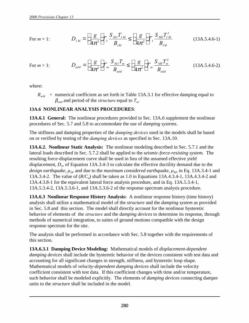
2000 Provisions Chapter 13
280280
For m = 1: (13A.5.4.6-1)Dg S T g S T
MM M MS M
11 1
1M
12
1MB B=
≤
4 42 1 2 1π π
Γ Γ
For m > 1: (13A.5.4.6-2)Dg S T
B
g S T
BM m
mM
mMS m
mM
mM m1=
≤
4 42 2
2
π πΓ Γ
where:
BmM = numerical coefficient as set forth in Table 13A.3.1 for effective damping equal to$mM and period of the structure equal to Tm.
13A.6 NONLINEAR ANALYSIS PROCEDURES:
13A.6.1 General: The nonlinear procedures provided in Sec. 13A.6 supplement the nonlinearprocedures of Sec. 5.7 and 5.8 to accommodate the use of damping systems.
The stiffness and damping properties of the damping devices used in the models shall be basedon or verified by testing of the damping devices as specified in Sec. 13A.10.
13A.6.2. Nonlinear Static Analysis: The nonlinear modeling described in Sec. 5.7.1 and thelateral loads described in Sec. 5.7.2 shall be applied to the seismic-force-resisting system. Theresulting force-displacement curve shall be used in lieu of the assumed effective yielddisplacement, DY, of Equation 13A.3.4-3 to calculate the effective ductility demand due to thedesign earthquake, µD, and due to the maximum considered earthquake, µM, in Eq. 13A.3.4-1 and13A.3.4-2. The value of (R/Cd) shall be taken as 1.0 in Equations 13A.4.3.4-1, 13A.4.3.4-2 and13A.4.3.8-1 for the equivalent lateral force analysis procedure, and in Eq. 13A.5.3.4-1,13A.5.3.4-2, 13A.5.3.6-1, and 13A.5.3.6-2 of the response spectrum analysis procedure.
13A.6.3 Nonlinear Response History Analysis: A nonlinear response history (time history)analysis shall utilize a mathematical model of the structure and the damping system as providedin Sec. 5.8 and this section. The model shall directly account for the nonlinear hystereticbehavior of elements of the structure and the damping devices to determine its response, throughmethods of numerical integration, to suites of ground motions compatible with the designresponse spectrum for the site.
The analysis shall be performed in accordance with Sec. 5.8 together with the requirements ofthis section.
13A.6.3.1 Damping Device Modeling: Mathematical models of displacement-dependentdamping devices shall include the hysteretic behavior of the devices consistent with test data andaccounting for all significant changes in strength, stiffness, and hysteretic loop shape. Mathematical models of velocity-dependent damping devices shall include the velocitycoefficient consistent with test data. If this coefficient changes with time and/or temperature,such behavior shall be modeled explicitly. The elements of damping devices connecting damperunits to the structure shall be included in the model.

Base Isolation and Energy Dissipation
281281
Exception: If the properties of the damping devices are expected to change during theduration of the time history analysis, the dynamic response may be enveloped by theupper and lower limits of device properties. All these limit cases for variable deviceproperties must satisfy the same conditions as if the time dependent behavior of thedevices were explicitly modeled.
13A.6.3.2 Response Parameters: In addition to the response parameters given in Sec. 5.8.3,the design earthquake and maximum considered earthquake displacements, velocities, and forcesof the damping devices shall be determined.
13A.7 SEISMIC LOAD CONDITIONS AND ACCEPTANCE CRITERIA:
13A.7.1 General: Design forces and displacements determined in accordance with theequivalent lateral force analysis procedures of Sec. 13A.4 or the response spectrum analysisprocedure of Sec. 13.5 shall be checked using the strength design criteria of these Provisions andthe seismic loading conditions of the following sections.
13A.7.2 Seismic-Force-Resisting System: The seismic-force-resisting system shall meet thedesign provisions of Sec. 5.2.2 using seismic base shear and design forces determined inaccordance with Sec. 13A.4.3 or Sec 13A.5.3.
The design earthquake story drift, ∆D, as determined in either Sec. 13A.4.4.4 or 13A.5.4.4 shallnot exceed (R/Cd) times the allowable story drift, as obtained from Table 5.2.8, considering theeffects of torsion as required in Sec. 5.2.8.
13A.7.3 Damping System: The damping system shall meet the provisions of Sec. 5.2.2 forseismic design forces determined in accordance with Sec. 13A.7.3.1 and the seismic loadingconditions of Sec. 13A.7.3.2 and Sec. 13A.5.4.
13A.7.3.1 Modal Damping System Design Forces: Modal damping system design forces shallbe calculated on the basis of the type of damping devices, and the modal design storydisplacements and modal design story velocities determined in accordance with either Sec.13A.4.4 or Sec. 13A.5.4.
Exception: Modal design story displacements and velocities determined in accordancewith either Sec. 13A.4.4 or Sec. 13A.5.4 shall be increased as required to envelop totaldesign story displacements and velocities determined in accordance with Sec. 13A.6,when Sec. 13A.2.6.4.3 requires peak response to be confirmed by time history analysis.
1. Displacement-Dependent Damping Devices: Design seismic force in displacement-dependent damping devices shall be based on the maximum force in the device atdisplacements up to and including the design earthquake story drift, )D.
2. Velocity-Dependent Damping Devices: Design seismic force in each mode of vibrationof velocity-dependent damping devices shall be based on the maximum force in thedevice at velocities up to and including the design earthquake story velocity of the modeof interest.

2000 Provisions Chapter 13
282282
Displacements and velocities used to determine design forces in damping devices at each storyshall account for the angle of orientation from horizontal and consider the effects of increasedfloor response due to torsional motions.
13A.7.3.2 Seismic Load Conditions and Combination of Modal Responses: Seismic designforce, QE, in each element of the damping system due to horizontal earthquake load shall be takenas the maximum force of the following three loading conditions:
1. Stage of Maximum Displacement: Seismic design force at the stage of maximumdisplacement shall be calculated in accordance with the following equation:
(13A.7.3.2-1)( )Q Q QE o mSFRSm
DSD= ±∑Ω 2
where:
QmSFRS = Force in an element of the damping system equal to the design seismic forceof the mth mode of vibration of the seismic-force-resisting system in thedirection of interest.
QDSD = Force in an element of the damping system required to resist design seismicforces of displacement-dependent damping devices.
Seismic forces in elements of the damping system, QDSD, shall be calculated by imposingdesign forces of displacement-dependent damping devices on the damping system as pseudo-static forces. Design seismic forces of displacement-dependent damping devices shall beapplied in both positive and negative directions at peak displacement of the structure.
2. Stage of Maximum Velocity: Seismic design force at the stage of maximum velocity shallbe calculated in accordance with the following equation:
(13A.7.3.2-2)( )Q QE mDSVm
= ∑ 2
where:
QmDSV = Force in an element of the damping system required to resist design seismicforces of velocity-dependent damping devices due to the mth mode ofvibration of structure in the direction of interest.
Modal seismic design forces in elements of the damping system, QmDSV, shall be calculated byimposing modal design forces of velocity-dependent devices on the non-deformed dampingsystem as pseudo-static forces. Modal seismic design forces shall be applied in directionsconsistent with the deformed shape of the mode of interest. Horizontal restraint forces shallbe applied at each floor Level i of the non-deformed damping system concurrent with thedesign forces in velocity-dependent damping devices such that the horizontal displacement ateach level of the structure is zero. At each floor Level i, restraint forces shall be proportionalto and applied at the location of each mass point.
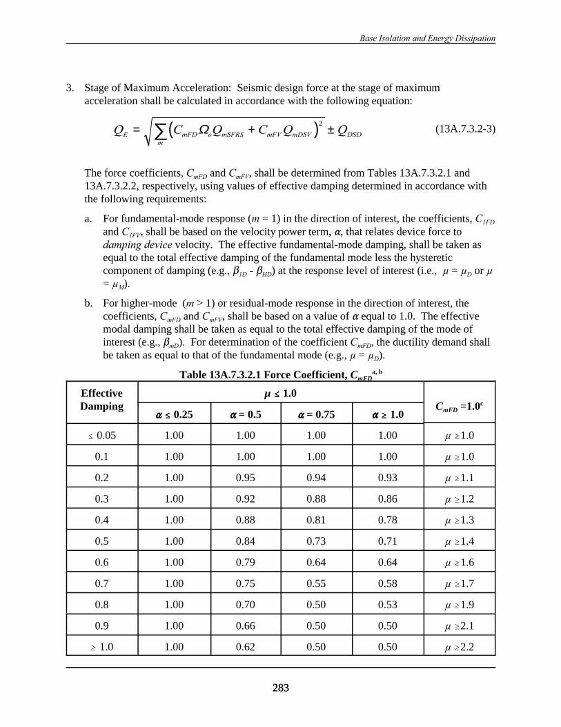
Base Isolation and Energy Dissipation
283283
3. Stage of Maximum Acceleration: Seismic design force at the stage of maximum
acceleration shall be calculated in accordance with the following equation:
(13A.7.3.2-3)( )Q C Q C Q QE mFD o mSFRS mFV mDSVm
DSD= + ±∑ Ω 2
The force coefficients, CmFD and CmFV, shall be determined from Tables 13A.7.3.2.1 and13A.7.3.2.2, respectively, using values of effective damping determined in accordance withthe following requirements:
a. For fundamental-mode response (m = 1) in the direction of interest, the coefficients, C1FD
and C1FV, shall be based on the velocity power term, ", that relates device force todamping device velocity. The effective fundamental-mode damping, shall be taken asequal to the total effective damping of the fundamental mode less the hystereticcomponent of damping (e.g., $1D - $HD) at the response level of interest (i.e., µ = µD or µ= µM).
b. For higher-mode (m > 1) or residual-mode response in the direction of interest, thecoefficients, CmFD and CmFV, shall be based on a value of " equal to 1.0. The effectivemodal damping shall be taken as equal to the total effective damping of the mode ofinterest (e.g., $mD). For determination of the coefficient CmFD, the ductility demand shallbe taken as equal to that of the fundamental mode (e.g., µ = µD).
Table 13A.7.3.2.1 Force Coefficient, CmFDa, b
EffectiveDamping
µ #### 1.0CmFD =1.0c
"""" #### 0.25 """" = 0.5 """" = 0.75 """" $$$$ 1.0
# 0.05 1.00 1.00 1.00 1.00 µ $1.0
0.1 1.00 1.00 1.00 1.00 µ $1.0
0.2 1.00 0.95 0.94 0.93 µ $1.1
0.3 1.00 0.92 0.88 0.86 µ $1.2
0.4 1.00 0.88 0.81 0.78 µ $1.3
0.5 1.00 0.84 0.73 0.71 µ $1.4
0.6 1.00 0.79 0.64 0.64 µ $1.6
0.7 1.00 0.75 0.55 0.58 µ $1.7
0.8 1.00 0.70 0.50 0.53 µ $1.9
0.9 1.00 0.66 0.50 0.50 µ $2.1
$ 1.0 1.00 0.62 0.50 0.50 µ $2.2

2000 Provisions Chapter 13
EffectiveDamping
µ #### 1.0CmFD =1.0c
"""" #### 0.25 """" = 0.5 """" = 0.75 """" $$$$ 1.0
284284
a Unless analysis or test data support other values, the force coefficient CmFD for visco-elasticsystems shall be taken as 1.0.b Interpolation shall be used for intermediate values of effective damping, ", and µ.c CmFD shall be taken as equal to 1.0 for values of µ greater than or equal to the values shown.
Table 13A.7.3.2.2 Force Coefficient, CmFV a, b
EffectiveDamping
"""" #### 0.25 """" = 0.5 """" = 0.75 """" $$$$ 1.0
# 0.05 1.00 0.35 0.20 0.10
0.1 1.00 0.44 0.31 0.20
0.2 1.00 0.56 0.46 0.37
0.3 1.00 0.64 0.58 0.51
0.4 1.00 0.70 0.69 0.62
0.5 1.00 0.75 0.77 0.71
0.6 1.00 0.80 0.84 0.77
0.7 1.00 0.83 0.90 0.81
0.8 1.00 0.90 0.94 0.90
0.9 1.00 1.00 1.00 1.00
$ 1.0 1.00 1.00 1.00 1.00
a Unless analysis or test data support other values, the force coefficient CmFD for visco-elastic systems shall be taken as 1.0.b Interpolation shall be used for intermediate values of effective damping, ", and µ.
13A.7.3.3 Combination of Load Effects: The effects on the damping system and itscomponents due to gravity loads and seismic forces shall be combined in accordance with Sec.5.2.7 using the effect of horizontal seismic forces, QE, determined in accordance with Sec.13A.7.3.2.
Exception: The reliability factor, D, shall be taken as equal to 1.0 in all cases and thespecial load combinations of Sec. 5.2.7.1 need not apply to the design of the dampingsystem.
13A.7.3.4 Inelastic Response Limits: Elements of the damping system may exceed strengthlimits for design loads provided it is shown by analysis or test that:

Base Isolation and Energy Dissipation
285285
1. Inelastic response does not adversely affect damping system function.
2. Element forces calculated in accordance with Sec. 13A.7.3.2, using a value of So, taken asequal to 1.0, do not exceed the strength required to meet the load combinations of Sec. 5.2.7.
13A.8 DETAILED SYSTEM REQUIREMENTS:
13A.8.1 Damping Device Design: The design, construction and installation of damping devicesshall be based on maximum earthquake response and the following load conditions:
1. Low-cycle, large displacement degradation due to seismic loads;
2. High-cycle, small-displacement degradation due to wind, thermal or other cyclic loads;
3. Forces or displacements due to gravity loads;
4. Adhesion of device parts due to corrosion or abrasion, biodegradation, moisture or chemicalexposure; and
5. Exposure to environmental conditions, including but not limited to temperature, humidity,moisture, radiation (e.g., ultraviolet light) and reactive or corrosive substances (e.g., saltwater).
Damping devices subject to failure by low-cycle fatigue shall resist wind forces without slip,movement, or inelastic cycling.
The design of damping device shall incorporate the range of thermal conditions, device wear,manufacturing tolerances, and other effects that cause device properties to vary during thelifetime of the device.
13A.8.2 Multi-Axis Movement: Connection points of damping devices shall provide sufficientarticulation to accommodate simultaneous longitudinal, lateral, and vertical displacements of thedamping system.
13A.8.3 Inspection and Periodic Testing: Means of access for inspection and removal of alldamping devices shall be provided.
The registered design professional responsible for design of the structure shall establish anappropriate inspection and testing schedule for each type of damping device to ensure that thedevices respond in a dependable manner throughout device design life. The degree of inspectionand testing shall reflect the established in-service history of the damping devices, and thelikelihood of change in properties over the design life of devices.
13A.8.4 Manufacturing Quality Control: The registered design professional responsible fordesign of the structure shall establish a quality control plan for the manufacture of dampingdevices. As a minimum, this plan shall include the testing requirements of Sec. 13A.10.3.
13A.9 DESIGN REVIEW:
13A.9.1 General: Review of the design of the damping system and related test programs shallbe performed by an independent engineering panel including persons licensed in the appropriatedisciplines and experienced in seismic analysis including the theory and application of energydissipation methods.
2000 Provisions Chapter 13
286286
13A.9.2 Review Scope: The design review shall include the following:
1. Review of the earthquake ground motions used for design.
2. Review of design parameters of damping devices, including device test requirements, devicemanufacturing quality control and assurance, and scheduled maintenance and inspectionrequirements.
3. Review of nonlinear analysis methods incorporating the requirements of Sec. 5.8.4.
4. Review of the preliminary design of the seismic-force-resisting system and the dampingsystem.
5. Review of the final design of the seismic-force-resisting system and the damping system andall supporting analyses.
13A.10 REQUIRED TESTS OF DAMPING DEVICES:
13A.10.1 General: The force-velocity-displacement and damping properties used for the designof the damping system shall be based on the prototype tests of a selected number of dampingdevices, as specified in Sec. 13A.10.2.1.
The fabrication and quality control procedures used for all prototype and production dampingdevices shall be identical.
13A.10.2 Prototype Tests:
13A.10.2.1 General: The following tests shall be performed separately on two full-sizedamping devices of each type and size used in the design, in the order listed below.
Representative sizes of each type of device may be used for prototype testing, provided both ofthe following conditions are met:
(1) Fabrication and quality control procedures are identical for each type and size of devicesused in the structure.
(2) Prototype testing of representative sizes is accepted by the registered design professionalresponsible for design of the structure.
Test specimens shall not be used for construction, unless they are accepted by the registereddesign professional responsible for design of the structure and meet the requirements of Sec.13A.10.2 and Sec. 13A.10.3.
13A.10.2.2 Data Recording: The force-deflection relationship for each cycle of each test shallbe recorded.
13A.10.2.3 Sequence and Cycles of Testing: For the following test sequences, each dampingdevice shall be subjected to gravity load effects and thermal environments representative of theinstalled condition. For seismic testing, the displacement in the devices calculated for the
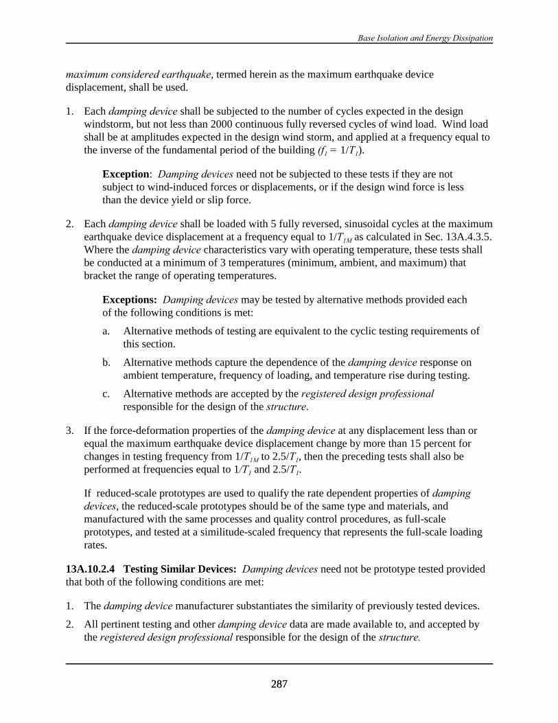
Base Isolation and Energy Dissipation
287287
maximum considered earthquake, termed herein as the maximum earthquake devicedisplacement, shall be used.
1. Each damping device shall be subjected to the number of cycles expected in the designwindstorm, but not less than 2000 continuous fully reversed cycles of wind load. Wind loadshall be at amplitudes expected in the design wind storm, and applied at a frequency equal tothe inverse of the fundamental period of the building (f1 = 1/T1).
Exception: Damping devices need not be subjected to these tests if they are notsubject to wind-induced forces or displacements, or if the design wind force is lessthan the device yield or slip force.
2. Each damping device shall be loaded with 5 fully reversed, sinusoidal cycles at the maximumearthquake device displacement at a frequency equal to 1/T1M as calculated in Sec. 13A.4.3.5. Where the damping device characteristics vary with operating temperature, these tests shallbe conducted at a minimum of 3 temperatures (minimum, ambient, and maximum) thatbracket the range of operating temperatures.
Exceptions: Damping devices may be tested by alternative methods provided eachof the following conditions is met:
a. Alternative methods of testing are equivalent to the cyclic testing requirements ofthis section.
b. Alternative methods capture the dependence of the damping device response onambient temperature, frequency of loading, and temperature rise during testing.
c. Alternative methods are accepted by the registered design professionalresponsible for the design of the structure.
3. If the force-deformation properties of the damping device at any displacement less than orequal the maximum earthquake device displacement change by more than 15 percent forchanges in testing frequency from 1/T1M to 2.5/T1, then the preceding tests shall also beperformed at frequencies equal to 1/T1 and 2.5/T1.
If reduced-scale prototypes are used to qualify the rate dependent properties of dampingdevices, the reduced-scale prototypes should be of the same type and materials, andmanufactured with the same processes and quality control procedures, as full-scaleprototypes, and tested at a similitude-scaled frequency that represents the full-scale loadingrates.
13A.10.2.4 Testing Similar Devices: Damping devices need not be prototype tested providedthat both of the following conditions are met:
1. The damping device manufacturer substantiates the similarity of previously tested devices.
2. All pertinent testing and other damping device data are made available to, and accepted bythe registered design professional responsible for the design of the structure.
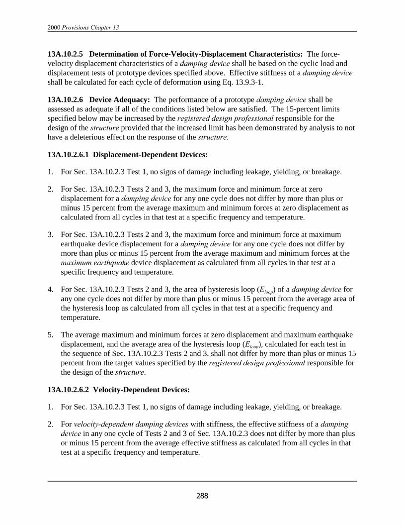
2000 Provisions Chapter 13
288288
13A.10.2.5 Determination of Force-Velocity-Displacement Characteristics: The force-velocity displacement characteristics of a damping device shall be based on the cyclic load anddisplacement tests of prototype devices specified above. Effective stiffness of a damping deviceshall be calculated for each cycle of deformation using Eq. 13.9.3-1.
13A.10.2.6 Device Adequacy: The performance of a prototype damping device shall beassessed as adequate if all of the conditions listed below are satisfied. The 15-percent limitsspecified below may be increased by the registered design professional responsible for thedesign of the structure provided that the increased limit has been demonstrated by analysis to nothave a deleterious effect on the response of the structure.
13A.10.2.6.1 Displacement-Dependent Devices:
1. For Sec. 13A.10.2.3 Test 1, no signs of damage including leakage, yielding, or breakage.
2. For Sec. 13A.10.2.3 Tests 2 and 3, the maximum force and minimum force at zerodisplacement for a damping device for any one cycle does not differ by more than plus orminus 15 percent from the average maximum and minimum forces at zero displacement ascalculated from all cycles in that test at a specific frequency and temperature.
3. For Sec. 13A.10.2.3 Tests 2 and 3, the maximum force and minimum force at maximumearthquake device displacement for a damping device for any one cycle does not differ bymore than plus or minus 15 percent from the average maximum and minimum forces at themaximum earthquake device displacement as calculated from all cycles in that test at aspecific frequency and temperature.
4. For Sec. 13A.10.2.3 Tests 2 and 3, the area of hysteresis loop (Eloop) of a damping device forany one cycle does not differ by more than plus or minus 15 percent from the average area ofthe hysteresis loop as calculated from all cycles in that test at a specific frequency andtemperature.
5. The average maximum and minimum forces at zero displacement and maximum earthquakedisplacement, and the average area of the hysteresis loop (Eloop), calculated for each test inthe sequence of Sec. 13A.10.2.3 Tests 2 and 3, shall not differ by more than plus or minus 15percent from the target values specified by the registered design professional responsible forthe design of the structure.
13A.10.2.6.2 Velocity-Dependent Devices:
1. For Sec. 13A.10.2.3 Test 1, no signs of damage including leakage, yielding, or breakage.
2. For velocity-dependent damping devices with stiffness, the effective stiffness of a dampingdevice in any one cycle of Tests 2 and 3 of Sec. 13A.10.2.3 does not differ by more than plusor minus 15 percent from the average effective stiffness as calculated from all cycles in thattest at a specific frequency and temperature.

Base Isolation and Energy Dissipation
289289
3. For Sec. 13A.10.2.3 Tests 2 and 3, the maximum force and minimum force at zerodisplacement for a damping device for any one cycle does not differ by more than plus orminus 15 percent from the average maximum and minimum forces at zero displacement ascalculated from all cycles in that test at a specific frequency and temperature.
4. For Sec. 13A.10.2.3 Tests 2 and 3, the area of hysteresis loop (Eloop) of a damping device forany one cycle does not differ by more than plus or minus 15 percent from the average area ofthe hysteresis loop as calculated from all cycles in that test at a specific frequency andtemperature.
5. The average maximum and minimum forces at zero displacement, effective stiffness (fordamping devices with stiffness only), and average area of the hysteresis loop (Eloop)calculated for each test in the sequence of Sec. 13A.10.2.3 Tests 2 and 3, shall not differ bymore than plus or minus 15 percent from the target values specified by the registered designprofessional responsible for the design of the structure.
13A.10.3 Production Testing: Prior to installation in a building, damping devices shall betested to ensure that their force-velocity-displacement characteristics fall within the limits set bythe registered design professional responsible for the design of the structure. The scope andfrequency of the production-testing program shall be determined by the registered designprofessional responsible for the design of the structure.

291291
Chapter 14
NONBUILDING STRUCTURE DESIGN REQUIREMENTS
14.1 GENERAL:
14.1.1 Scope: Nonbuilding structures considered by the Provisions include all self-supportingstructures which carry gravity loads, with the exception of: buildings, vehicular and railroadbridges, nuclear power generation plants, offshore platforms, and dams. Nonbuilding structuresare supported by the earth or supported by other structures, and shall be designed and detailedto resist the minimum lateral forces specified in this chapter . Design shall conform to theapplicable requirements of the Provisions as modified by this chapter. Nonbuilding structuresthat are beyond the scope of this section shall be designed in accordance with approvedstandards. Approved standards as referenced herein shall consist of standards approved by theauthority having jurisdiction and shall be applicable to the specific type of nonbuilding structure.
The design of nonbuilding structures shall provide sufficient stiffness, strength, and ductility,consistent with the requirements specified herein for buildings, to resist the effects of seismicground motions as represented by the following:
a. Applicable strength and other design criteria shall be obtained from other sections of theProvisions or its referenced codes and standards.
b. When applicable strength and other design criteria are not contained in or referenced by theProvisions, such criteria shall be obtained from approved standards. Where approved standards define acceptance criteria in terms of allowable stresses as opposed to strength, thedesign seismic forces shall be obtained from the Provisions and reduced by a factor of 1.4 foruse with allowable stresses. Allowable stress increases used in approved standards arepermitted. Detailing shall be in accordance with the approved standards.
14.2 REFERENCES:
ACI 313 American Concrete Institute (ACI), Standard Practice for the Design andConstruction of Concrete Silos and Stacking Tubes for Storing GranularMaterials, ACI 313, 1997
ACI 350.3 American Concrete Institute (ACI), Standard Practice for the SeismicDesign of Liquid-Containing Concrete Structures, ACI 350.3/350.3R,2001
ACI 371R-98 American Concrete Institute (ACI), Guide to the Analysis, Design, andConstruction of Concrete-Pedestal Water Towers, ACI 371R, 1995
ANSI K61.1 American National Standards Institute (ANSI), Safety Requirements forthe Storage and Handling of Anhydrous Ammonia, ANSI K61.1
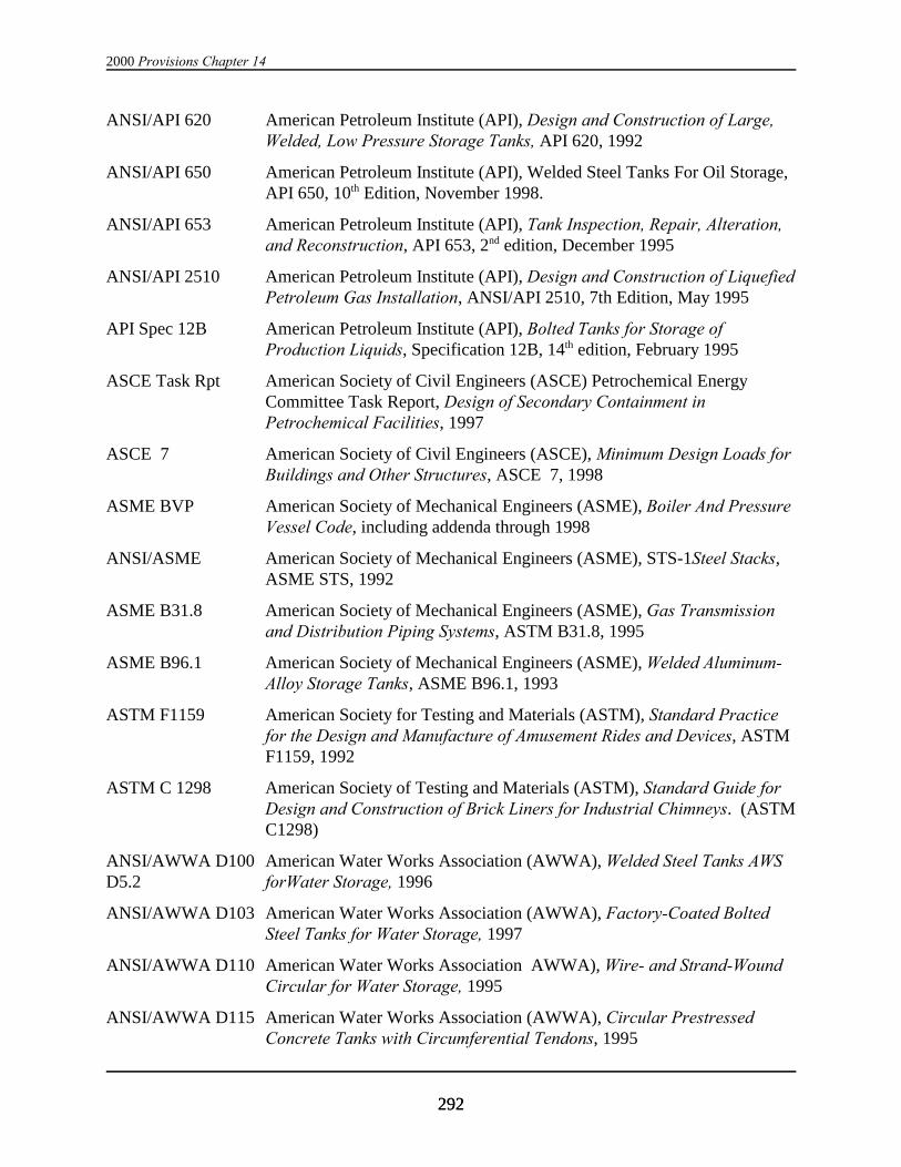
2000 Provisions Chapter 14
292292
ANSI/API 620 American Petroleum Institute (API), Design and Construction of Large,Welded, Low Pressure Storage Tanks, API 620, 1992
ANSI/API 650 American Petroleum Institute (API), Welded Steel Tanks For Oil Storage,API 650, 10th Edition, November 1998.
ANSI/API 653 American Petroleum Institute (API), Tank Inspection, Repair, Alteration,and Reconstruction, API 653, 2nd edition, December 1995
ANSI/API 2510 American Petroleum Institute (API), Design and Construction of LiquefiedPetroleum Gas Installation, ANSI/API 2510, 7th Edition, May 1995
API Spec 12B American Petroleum Institute (API), Bolted Tanks for Storage ofProduction Liquids, Specification 12B, 14th edition, February 1995
ASCE Task Rpt American Society of Civil Engineers (ASCE) Petrochemical EnergyCommittee Task Report, Design of Secondary Containment inPetrochemical Facilities, 1997
ASCE 7 American Society of Civil Engineers (ASCE), Minimum Design Loads forBuildings and Other Structures, ASCE 7, 1998
ASME BVP American Society of Mechanical Engineers (ASME), Boiler And PressureVessel Code, including addenda through 1998
ANSI/ASME American Society of Mechanical Engineers (ASME), STS-1Steel Stacks,ASME STS, 1992
ASME B31.8 American Society of Mechanical Engineers (ASME), Gas Transmissionand Distribution Piping Systems, ASTM B31.8, 1995
ASME B96.1 American Society of Mechanical Engineers (ASME), Welded Aluminum-Alloy Storage Tanks, ASME B96.1, 1993
ASTM F1159 American Society for Testing and Materials (ASTM), Standard Practicefor the Design and Manufacture of Amusement Rides and Devices, ASTMF1159, 1992
ASTM C 1298 American Society of Testing and Materials (ASTM), Standard Guide forDesign and Construction of Brick Liners for Industrial Chimneys. (ASTMC1298)
ANSI/AWWA D100 American Water Works Association (AWWA), Welded Steel Tanks AWSD5.2 forWater Storage, 1996
ANSI/AWWA D103 American Water Works Association (AWWA), Factory-Coated BoltedSteel Tanks for Water Storage, 1997
ANSI/AWWA D110 American Water Works Association AWWA), Wire- and Strand-WoundCircular for Water Storage, 1995
ANSI/AWWA D115 American Water Works Association (AWWA), Circular PrestressedConcrete Tanks with Circumferential Tendons, 1995
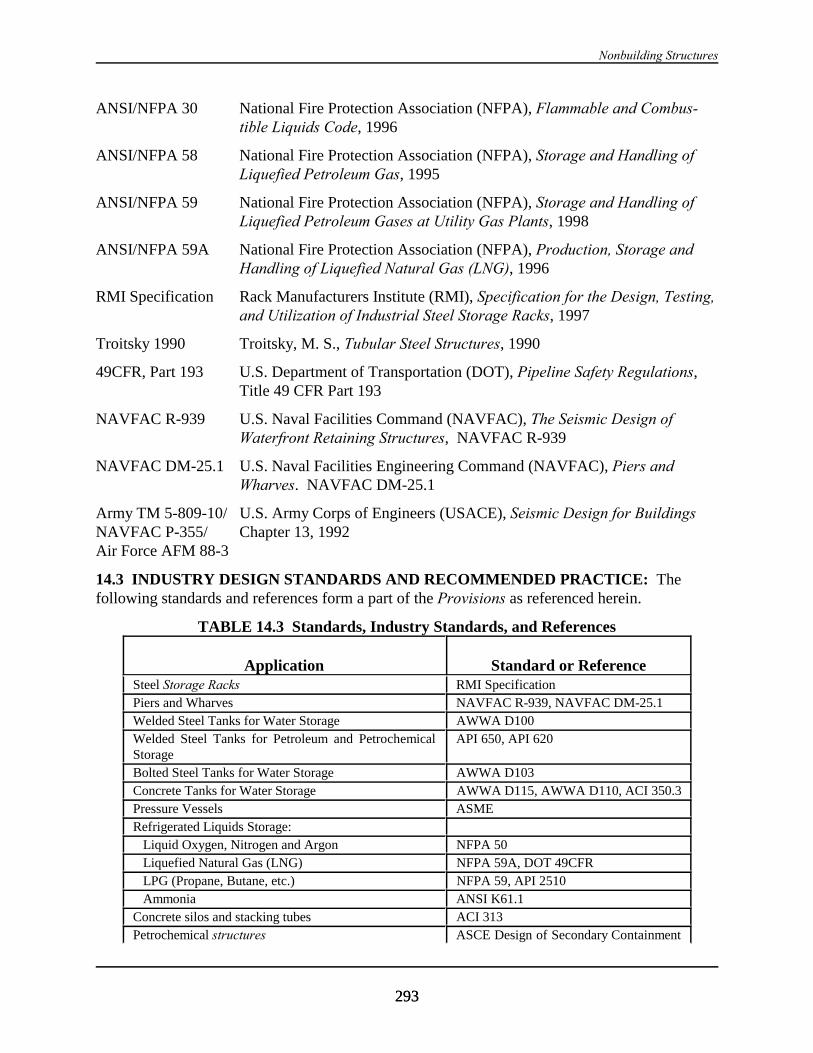
Nonbuilding Structures
293293
ANSI/NFPA 30 National Fire Protection Association (NFPA), Flammable and Combus-tible Liquids Code, 1996
ANSI/NFPA 58 National Fire Protection Association (NFPA), Storage and Handling ofLiquefied Petroleum Gas, 1995
ANSI/NFPA 59 National Fire Protection Association (NFPA), Storage and Handling ofLiquefied Petroleum Gases at Utility Gas Plants, 1998
ANSI/NFPA 59A National Fire Protection Association (NFPA), Production, Storage andHandling of Liquefied Natural Gas (LNG), 1996
RMI Specification Rack Manufacturers Institute (RMI), Specification for the Design, Testing,and Utilization of Industrial Steel Storage Racks, 1997
Troitsky 1990 Troitsky, M. S., Tubular Steel Structures, 1990
49CFR, Part 193 U.S. Department of Transportation (DOT), Pipeline Safety Regulations,Title 49 CFR Part 193
NAVFAC R-939 U.S. Naval Facilities Command (NAVFAC), The Seismic Design ofWaterfront Retaining Structures, NAVFAC R-939
NAVFAC DM-25.1 U.S. Naval Facilities Engineering Command (NAVFAC), Piers andWharves. NAVFAC DM-25.1
Army TM 5-809-10/ U.S. Army Corps of Engineers (USACE), Seismic Design for BuildingsNAVFAC P-355/ Chapter 13, 1992Air Force AFM 88-3
14.3 INDUSTRY DESIGN STANDARDS AND RECOMMENDED PRACTICE: Thefollowing standards and references form a part of the Provisions as referenced herein.
TABLE 14.3 Standards, Industry Standards, and References
Application Standard or ReferenceSteel Storage Racks RMI SpecificationPiers and Wharves NAVFAC R-939, NAVFAC DM-25.1Welded Steel Tanks for Water Storage AWWA D100Welded Steel Tanks for Petroleum and PetrochemicalStorage
API 650, API 620
Bolted Steel Tanks for Water Storage AWWA D103Concrete Tanks for Water Storage AWWA D115, AWWA D110, ACI 350.3Pressure Vessels ASMERefrigerated Liquids Storage: Liquid Oxygen, Nitrogen and Argon NFPA 50 Liquefied Natural Gas (LNG) NFPA 59A, DOT 49CFR LPG (Propane, Butane, etc.) NFPA 59, API 2510 Ammonia ANSI K61.1Concrete silos and stacking tubes ACI 313Petrochemical structures ASCE Design of Secondary Containment
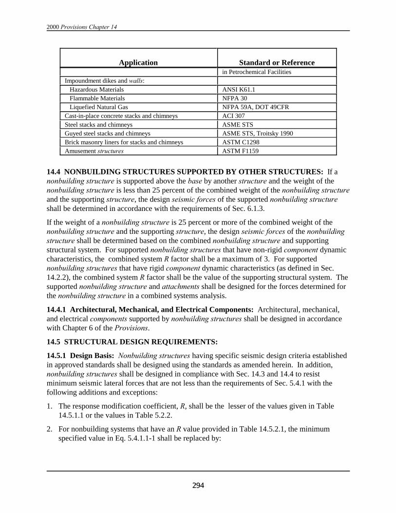
2000 Provisions Chapter 14
Application Standard or Reference
294294
in Petrochemical FacilitiesImpoundment dikes and walls: Hazardous Materials ANSI K61.1 Flammable Materials NFPA 30 Liquefied Natural Gas NFPA 59A, DOT 49CFRCast-in-place concrete stacks and chimneys ACI 307Steel stacks and chimneys ASME STSGuyed steel stacks and chimneys ASME STS, Troitsky 1990Brick masonry liners for stacks and chimneys ASTM C1298Amusement structures ASTM F1159
14.4 NONBUILDING STRUCTURES SUPPORTED BY OTHER STRUCTURES: If anonbuilding structure is supported above the base by another structure and the weight of thenonbuilding structure is less than 25 percent of the combined weight of the nonbuilding structureand the supporting structure, the design seismic forces of the supported nonbuilding structureshall be determined in accordance with the requirements of Sec. 6.1.3.
If the weight of a nonbuilding structure is 25 percent or more of the combined weight of thenonbuilding structure and the supporting structure, the design seismic forces of the nonbuildingstructure shall be determined based on the combined nonbuilding structure and supportingstructural system. For supported nonbuilding structures that have non-rigid component dynamiccharacteristics, the combined system R factor shall be a maximum of 3. For supportednonbuilding structures that have rigid component dynamic characteristics (as defined in Sec.14.2.2), the combined system R factor shall be the value of the supporting structural system. Thesupported nonbuilding structure and attachments shall be designed for the forces determined forthe nonbuilding structure in a combined systems analysis.
14.4.1 Architectural, Mechanical, and Electrical Components: Architectural, mechanical,and electrical components supported by nonbuilding structures shall be designed in accordancewith Chapter 6 of the Provisions.
14.5 STRUCTURAL DESIGN REQUIREMENTS:
14.5.1 Design Basis: Nonbuilding structures having specific seismic design criteria establishedin approved standards shall be designed using the standards as amended herein. In addition,nonbuilding structures shall be designed in compliance with Sec. 14.3 and 14.4 to resistminimum seismic lateral forces that are not less than the requirements of Sec. 5.4.1 with thefollowing additions and exceptions:
1. The response modification coefficient, R, shall be the lesser of the values given in Table14.5.1.1 or the values in Table 5.2.2.
2. For nonbuilding systems that have an R value provided in Table 14.5.2.1, the minimumspecified value in Eq. 5.4.1.1-1 shall be replaced by:

Nonbuilding Structures
295295
Cs = 0.14SDSI (14.2.1-1)
and the minimum value specified in Eq. 5.3.2.1-4 shall be replaced by:
Cs = 0.8S1I/R (14.2.1-2)
3. The overstrength factor, S0, shall be as given in Table 14.5.1.1 or Table 5.2.2..
4. The importance factor, I, shall be as given in Table 14.5.1.2 .
5. The height limitations shall be as given in Table 14.5.1.1 or Table 5.2.2.
6. The vertical distribution of the lateral seismic forces in nonbuilding structures covered bythis section shall be determined:
a. In accordance with the requirements of Sec. 5.4.3 or
b. In accordance with the procedures of Sec. 5.5 or
c. In accordance with an approved standard applicable to the specific nonbuildingstructure.
7. For nonbuilding structural systems containing liquids, gases, and granular solids supported atthe base as defined in Sec. 14.7.3.1, the minimum seismic design force shall not be less thanthat required by the approved standard for the specific system.
8. Irregular structures per Sec. 5.2.3 at sites where the seismic coefficient SDS is greater than orequal to 0.50 that cannot be modeled as a single mass shall use the procedures of Sec. 5.5.
9. Where an approved standard provides a basis for the earthquake resistant design of aparticular type of nonbuilding structure such a standard may be used subject to the followinglimitations:
a. The seismic ground acceleration and seismic coefficient shall be in conformance withthe requirements of Sec. 4.1 and 4.2, respectively.
b. The values for total lateral force and total base overturning moment used in designshall not be less than 80 percent of the base shear value and overturning moment,each adjusted for the effects of soil-structure interaction that would be obtained usingthe Provisions.
10. The base shear is permitted to be reduced in accordance with Sec. 5.5.7 to account for theeffects of soil-structure interaction. In no case shall the reduced base shear, V, be less than0.7V.

2000 Provisions Chapter 14
296296
14.5.1.1 Seismic Factors:
TABLE 14.5.1.1 Seismic Coefficients for Nonbuilding Structures
Nonbuilding Structure Type R SSSS0 Cd Structural System and HeightLimits (ft)c
Seismic Design Category
A & B C D E & F
Nonbuilding frame systems:Concentric Braced Frames of SteelSpecial Concentric Braced Frames of Steel
See Table 5.2.2 NL
NLNLNL
NLNL
NLNL
Moment Resisting Frame Systems:Special Moment Frames of SteelOrdinary Moment Frames of SteelSpecial Moment Frames of ConcreteIntermediate Moment Frames of ConcreteOrdinary Moment Frames of Concrete
See Table 5.2.2 NL
NLNLNLNL
NLNLNLNL50
NL50NL50NP
NL50NL50NP
Steel Storage Racks 4 2 3-1/2 NL NL NL NL
Elevated tanks, vessels, bins, or hoppersa:On braced legsOn unbraced legsIrregular braced legs single pedestal or skirt sup-portedWelded steelConcrete
332
22
222
22
2-1/22-1/2
2
22
NLNLNL
NLNL
NLNLNL
NLNL
NLNLNL
NLNL
NLNLNL
NLNL
Horizontal, saddle supported welded steel vessels 3 2 2-1/2 NL NL NL NL
Tanks or vessels supported on structural towerssimilar to buildings
3 2 2 NL NL NL NL
Flat bottom, ground supported tanks, or vessels:Anchored (welded or bolted steel)Unanchored (welded or bolted steel)
Reinforced or prestressed concrete:Tanks with reinforced nonsliding baseTanks with anchored flexible base
Tanks with unanchored and unconstrained:Flexible baseOther material
32-1/2
23
1-1/21 -/2
22
22
1-1/21-1/2
2-1/22
22
1-1/21-1/2
NLNL
NLNL
NLNL
NLNL
NLNL
NLNL
NLNL
NLNL
NLNL
NLNL
NLNL
NLNL
Cast-in-place concrete silos, stacks, and chimneyshaving walls continuous to the foundation
3 1-3/4 3 NL NL NL NL
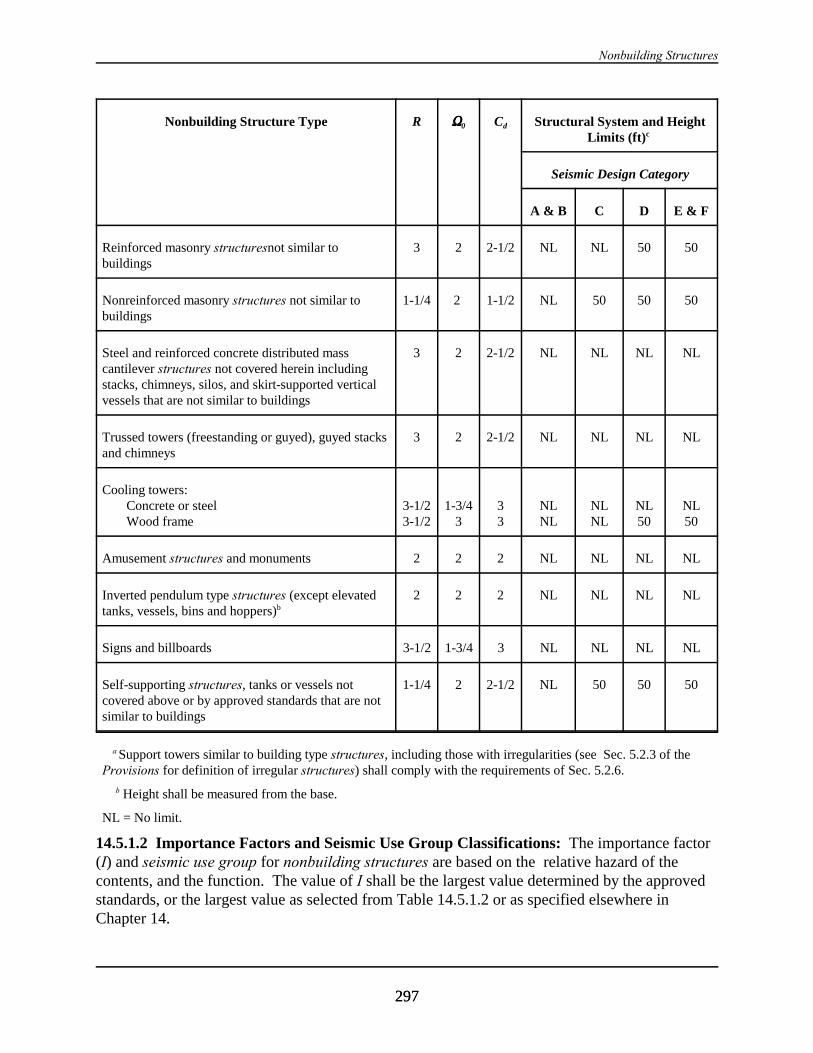
Nonbuilding Structures
Nonbuilding Structure Type R SSSS0 Cd Structural System and HeightLimits (ft)c
Seismic Design Category
A & B C D E & F
297297
Reinforced masonry structuresnot similar tobuildings
3 2 2-1/2 NL NL 50 50
Nonreinforced masonry structures not similar tobuildings
1-1/4 2 1-1/2 NL 50 50 50
Steel and reinforced concrete distributed masscantilever structures not covered herein includingstacks, chimneys, silos, and skirt-supported verticalvessels that are not similar to buildings
3 2 2-1/2 NL NL NL NL
Trussed towers (freestanding or guyed), guyed stacksand chimneys
3 2 2-1/2 NL NL NL NL
Cooling towers:Concrete or steelWood frame
3-1/23-1/2
1-3/43
33
NLNL
NLNL
NL50
NL50
Amusement structures and monuments 2 2 2 NL NL NL NL
Inverted pendulum type structures (except elevatedtanks, vessels, bins and hoppers)b
2 2 2 NL NL NL NL
Signs and billboards 3-1/2 1-3/4 3 NL NL NL NL
Self-supporting structures, tanks or vessels notcovered above or by approved standards that are notsimilar to buildings
1-1/4 2 2-1/2 NL 50 50 50
a Support towers similar to building type structures, including those with irregularities (see Sec. 5.2.3 of theProvisions for definition of irregular structures) shall comply with the requirements of Sec. 5.2.6.
b Height shall be measured from the base.
NL = No limit.
14.5.1.2 Importance Factors and Seismic Use Group Classifications: The importance factor(I) and seismic use group for nonbuilding structures are based on the relative hazard of thecontents, and the function. The value of I shall be the largest value determined by the approvedstandards, or the largest value as selected from Table 14.5.1.2 or as specified elsewhere inChapter 14.
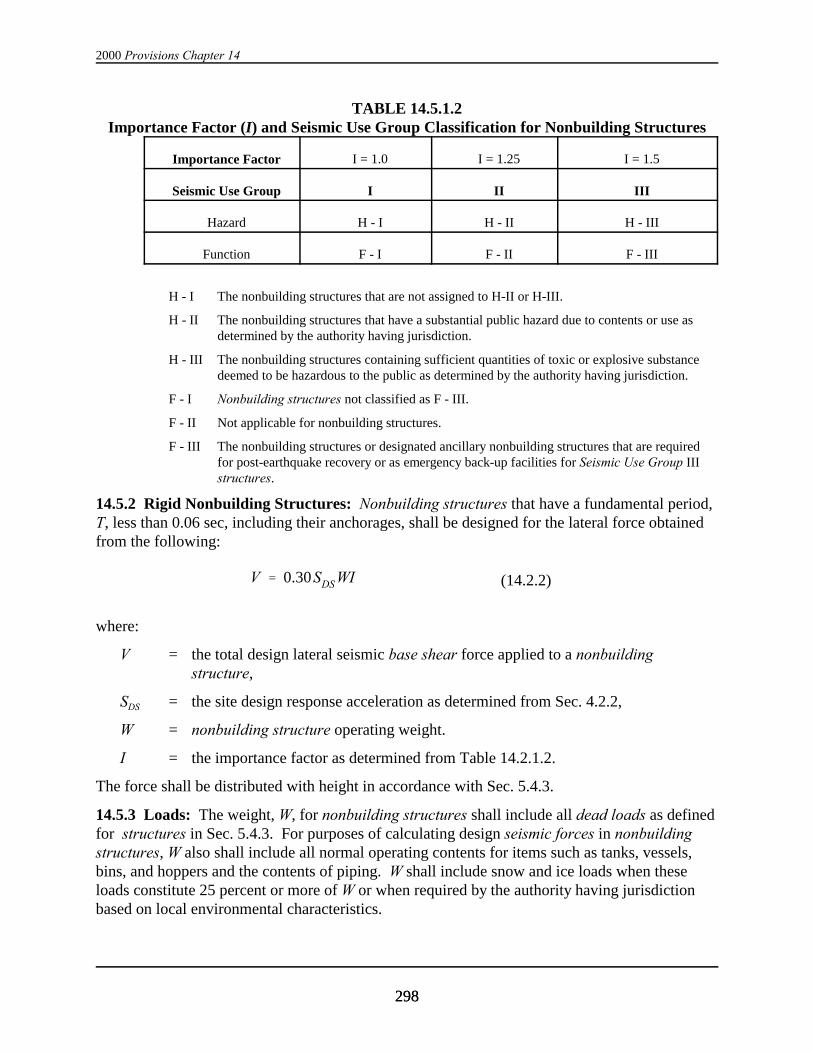
2000 Provisions Chapter 14
298298
V ' 0.30SDS WI (14.2.2)
TABLE 14.5.1.2Importance Factor (I) and Seismic Use Group Classification for Nonbuilding Structures
Importance Factor I = 1.0 I = 1.25 I = 1.5
Seismic Use Group I II III
Hazard H - I H - II H - III
Function F - I F - II F - III
H - I The nonbuilding structures that are not assigned to H-II or H-III.
H - II The nonbuilding structures that have a substantial public hazard due to contents or use asdetermined by the authority having jurisdiction.
H - III The nonbuilding structures containing sufficient quantities of toxic or explosive substancedeemed to be hazardous to the public as determined by the authority having jurisdiction.
F - I Nonbuilding structures not classified as F - III.
F - II Not applicable for nonbuilding structures.
F - III The nonbuilding structures or designated ancillary nonbuilding structures that are requiredfor post-earthquake recovery or as emergency back-up facilities for Seismic Use Group IIIstructures.
14.5.2 Rigid Nonbuilding Structures: Nonbuilding structures that have a fundamental period,T, less than 0.06 sec, including their anchorages, shall be designed for the lateral force obtainedfrom the following:
where:
V = the total design lateral seismic base shear force applied to a nonbuildingstructure,
SDS = the site design response acceleration as determined from Sec. 4.2.2,
W = nonbuilding structure operating weight.
I = the importance factor as determined from Table 14.2.1.2.
The force shall be distributed with height in accordance with Sec. 5.4.3.
14.5.3 Loads: The weight, W, for nonbuilding structures shall include all dead loads as definedfor structures in Sec. 5.4.3. For purposes of calculating design seismic forces in nonbuildingstructures, W also shall include all normal operating contents for items such as tanks, vessels,bins, and hoppers and the contents of piping. W shall include snow and ice loads when theseloads constitute 25 percent or more of W or when required by the authority having jurisdictionbased on local environmental characteristics.
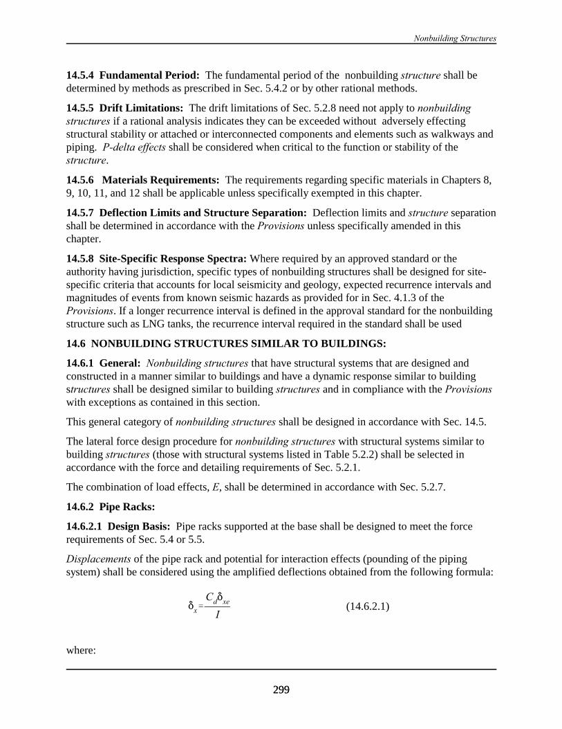
Nonbuilding Structures
299299
*x'Cd*xe
I(14.6.2.1)
14.5.4 Fundamental Period: The fundamental period of the nonbuilding structure shall bedetermined by methods as prescribed in Sec. 5.4.2 or by other rational methods.
14.5.5 Drift Limitations: The drift limitations of Sec. 5.2.8 need not apply to nonbuildingstructures if a rational analysis indicates they can be exceeded without adversely effectingstructural stability or attached or interconnected components and elements such as walkways andpiping. P-delta effects shall be considered when critical to the function or stability of thestructure.
14.5.6 Materials Requirements: The requirements regarding specific materials in Chapters 8,9, 10, 11, and 12 shall be applicable unless specifically exempted in this chapter.
14.5.7 Deflection Limits and Structure Separation: Deflection limits and structure separationshall be determined in accordance with the Provisions unless specifically amended in thischapter.
14.5.8 Site-Specific Response Spectra: Where required by an approved standard or theauthority having jurisdiction, specific types of nonbuilding structures shall be designed for site-specific criteria that accounts for local seismicity and geology, expected recurrence intervals andmagnitudes of events from known seismic hazards as provided for in Sec. 4.1.3 of theProvisions. If a longer recurrence interval is defined in the approval standard for the nonbuildingstructure such as LNG tanks, the recurrence interval required in the standard shall be used
14.6 NONBUILDING STRUCTURES SIMILAR TO BUILDINGS:
14.6.1 General: Nonbuilding structures that have structural systems that are designed andconstructed in a manner similar to buildings and have a dynamic response similar to buildingstructures shall be designed similar to building structures and in compliance with the Provisionswith exceptions as contained in this section.
This general category of nonbuilding structures shall be designed in accordance with Sec. 14.5.
The lateral force design procedure for nonbuilding structures with structural systems similar tobuilding structures (those with structural systems listed in Table 5.2.2) shall be selected inaccordance with the force and detailing requirements of Sec. 5.2.1.
The combination of load effects, E, shall be determined in accordance with Sec. 5.2.7.
14.6.2 Pipe Racks:
14.6.2.1 Design Basis: Pipe racks supported at the base shall be designed to meet the forcerequirements of Sec. 5.4 or 5.5.
Displacements of the pipe rack and potential for interaction effects (pounding of the pipingsystem) shall be considered using the amplified deflections obtained from the following formula:
where:
2000 Provisions Chapter 14
300300
Cd = the deflection amplification factor in Table 14.5.1.1,
*xe = the deflections determined using the prescribed seismic design forces of theProvisions, and
I = the importance factor determined from Table 14.5.1.2.
Exception: The importance factor, I, shall be determined from Table 14.5.1.2 for thecalculation of *xe.
See Sec. 3.3.11 for the design of piping systems and their attachments. Friction resulting fromgravity loads shall not be considered to provide resistance to seismic forces.
14.6.3 Steel Storage Racks: Steel storage racks supported at or below grade shall be designedin accordance with Sec. 14.6.3 and the following or, alternatively, with the method detailed inSection 2.7 of the RMI Specification provided that when determining the value of Ca in Sec.2.7.3 of the RMI Specification, the value of Cs is taken as equal to SDS/2.5, the value of Cv istaken as equal to SD1, and the value of Ip shall not be taken as less than that required in Sec. 6.1.5of the Provisions. In addition, the value of Cs in the RMI Specification shall not be less than0.14SDS. For storage racks supported above grade, the value of Cs in the RMI Specification shallnot be less than the value determined for Fp in accordance with Sec. 6.2 of the Provisions with Rp
taken as equal to R and ap taken as equal to 2.5.
14.6.3.1 General Requirements: Steel storage racks shall satisfy the force requirements of this section.
Exception: Steel storage racks supported at the base are permitted to be designed asstructures with an R of 4 provided that the requirements of Chapter 2 are met. Highervalues of R are permitted to be used when justified by test data approved in accordancewith Sec. 1.2.6 or when the detailing requirements of Chapter 5 and 10 are met. Theimportance factor I shall be taken equal to the Ip values in accordance with Sec. 6.1.5
14.6.3.2 Operating Weight: Steel storage racks shall be designed for each of the followingconditions of operating weight, W or Wp.
a. Weight of the rack plus every storage level loaded to 67 percent of its rated load capacity.
b. Weight of the rack plus the highest storage level only loaded to 100 percent of its rated loadcapacity.
The design shall consider the actual height of the center of mass of each storage load component.
14.6.3.3 Vertical Distribution of Seismic Forces: For all steel storage racks, the verticaldistribution of seismic forces shall be as specified in Sec. 5.4.3 and in accordance with thefollowing:
a. The base shear, V, of the typical structure shall be the base shear of the steel storage rackwhen loaded in accordance with Sec. 14.6.3.2.
b. The base of the structure shall be the floor supporting the steel storage rack. Each steelstorage level of the rack shall be treated as a level of the structure, with heights hi, and hx
measured from the base of the structure.
Nonbuilding Structures
301301
c. The factor k may be taken as 1.0.
d. The factor I shall be in accordance with Sec. 6.1.5.
14.6.3.4 Seismic Displacements: Steel storage rack installations shall accommodate theseismic displacement of the storage racks and their contents relative to all adjacent or attachedcomponents and elements. The assumed total relative displacement for storage racks shall be not less than 5 percent of the height above the base unless a smaller value is justified by test dataor analysis approved in accordance with Sec. 1.5.
14.6.4 Electrical Power Generating Facilities:
14.6.4.1 General: Electrical power generating facilities are power plants that generateelectricity by steam turbines, combustion turbines, diesel generators or similar turbo machinery.
14.6.4.2 Design Basis: Electrical power generating facilities shall be designed using theProvisions and the appropriate factors contained in Sec. 14.5.
14.6.5 Structural Towers for Tanks and Vessels:
14.6.5.1 General: Structural towers which support tanks and vessels shall be designed to meetthe provisions of Sec 14.4. In addition, the following special considerations shall be included:
a. The distribution of the lateral base shear from the tank or vessel onto the supportingstructure shall consider the relative stiffness of the tank and resisting structural elements.
b. The distribution of the vertical reactions from the tank or vessel onto the supporting structureshall consider the relative stiffness of the tank and resisting structural elements. When thetank or vessel is supported on grillage beams, the calculated vertical reaction due to weightand overturning shall be increased at least 20 percent to account for nonuniform support. Thegrillage beam and vessel attachment shall be designed for this increased design value.
c. Seismic displacements of the tank and vessel shall consider the deformation of the supportstructure when determining P-delta effects or evaluating required clearances to preventpounding of the tank on the structure.
14.6.6 Piers and Wharves:
14.6.6.1 General: Piers and wharves are structures located in waterfront areas that project intoa body of water or parallel the shore line.
14.6.6.2 Design Basis: Piers and wharves shall be designed to comply with the Provisions andapproved standards. Seismic forces on elements below the water level shall include the inertialforce of the mass of the displaced water. The additional seismic mass equal to the mass of thedisplaced water shall be included as a lumped mass on the submerged element, and shall beadded to the calculated seismic forces of the pier or wharf structure. Seismic dynamic forcesfrom the soil shall be determined by the registered design professional.
The design shall account for the effects of liquefaction on piers and wharfs as required.
14.7 NONBUILDING STRUCTURES NOT SIMILAR TO BUILDINGS:
2000 Provisions Chapter 14
302302
14.7.1 General: Nonbuilding structures that have structural systems that are designed andconstructed in a manner such that the dynamic response is not similar to buildings shall bedesigned in compliance with the Provisions with exceptions as contained in this section.
This general category of nonbuilding structures shall be designed in accordance with theProvisions and the specific applicable approved standards. Loads and load distributions shall notbe less than those determined in the Provisions.
The combination of load effects, E, shall be determined in accordance with Sec. 5.2.6.2.
Exception: The redundancy/reliability factor, D, per Sec. 5.2.4 shall be taken as 1.
14.7.2 Earth Retaining Structures:
14.7.2.1 General: This section applies to all earth retaining walls. The applied seismic forcesshall be determined in accordance with Sec. 7.5.1 with a geotechnical analysis prepared by aregistered design professional.
14.7.3 Tanks and Vessels:
14.7.3.1 General: This section applies to all tanks, vessels, bins, and silos and similarcontainers storing liquids, gases, and granular solids supported at the base (hereafter referred togenerically as tanks and vessels). Tanks and vessels covered herein include reinforced concrete,prestressed concrete, steel, and fiber-reinforced plastic materials.
14.7.3.2 Design Basis: Tanks and vessels storing liquids, gases, and granular solids shall bedesigned in accordance with the Provisions and shall be designed to meet the requirements of theapplicable approved standards shown in Table 14.3 and Chapter 4 of the Provisions as defined inthis section. Resistance to seismic forces shall be determined from a substantiated analysis basedon the approved standards shown in Table 14.3.
h. Damping for the convective (sloshing) force component shall be taken as 0.5 percent
i. Impulsive and convective components may be combined by the direct sum or the square rootof the sum of the square (SRSS) method when the modal periods are separated. If modalcoupling may occur, the complete quadratic combination (CQC) method shall be used.
j. Vertical component of ground acceleration shall be considered in accordance with theappropriate national standard. If the approved national standard permits the user the optionof including or excluding the vertical component of ground acceleration to comply with theProvisions, it shall be included. For tanks and vessels not covered by an approved nationalstandard, the vertical seismic force shall be defined as 67 percent of the equivalent lateralforce.
14.7.3.3 Strength and Ductility: Structural components and members that are part of the lateralsupport system shall be designed to provide the following:
a. Connections and attachments for anchorage and other lateral force resisting components shallbe designed to develop the strength of the anchor (e.g., minimum published yield strength, Fy
in direct tension, plastic bending moment) or So times the calculated element design load.
Nonbuilding Structures
303303
b. Penetrations, manholes, and openings in shell components shall be designed to maintain thestrength and stability of the shell to carry tensile and compressive membrane shell forces.
c. Support towers for tanks and vessels with irregular bracing, unbraced panels, asymmetricbracing, or concentrated masses shall be designed using the provisions of Sec. 5.2.3 forirregular structures. Support towers using chevron or eccentric braced framing shall complywith the requirements of Sec. 5. Support towers using tension only bracing shall be designedsuch that the full cross section of the tension element can yield during overload conditions.
d. Compression struts that resist the reaction forces from tension braces shall be designed toresist the lesser of the yield strength of the brace (Ag Fy), or So times the calculated tensionload in the brace.
e. The vessel stiffness relative to the support system (e.g., foundation, support tower, skirt) shallbe considered in determining forces in the vessel, the resisting components and theconnections.
f. For concrete liquid-containing structures, system ductility and energy dissipation underunfactored loads shall not be allowed to be achieved by inelastic deformations to such adegree as to jeopardize the serviceability of the structure. Stiffness degradation and energydissipation shall be allowed to be obtained either through limited microcracking, or by meansof lateral-force resistance mechanisms that dissipate energy without damaging the structure.
14.7.3.4 Flexibility of Piping Attachments: Piping systems connected to tanks and vesselsshall consider the potential movement of the connection points during earthquakes and providesufficient flexibility to avoid release of the product by failure of the piping system. The pipingsystem and supports shall be designed so as to not impart significant mechanical loading on theattachment to the tank or vessel shell. Local loads at piping connections shall be considered inthe design of the tank or vessel shell. Mechanical devices which add flexibility such as bellows,expansion joints, and other flexible apparatus may be used when they are designed for seismicloads and displacements.
Unless otherwise calculated, the minimum displacements in Table 14.7.3.4 shall be assumed. For attachment points located above the support or foundation elevation, the displacements inTable 14.7.3.4 shall be increased to account for drift of the tank or vessel.
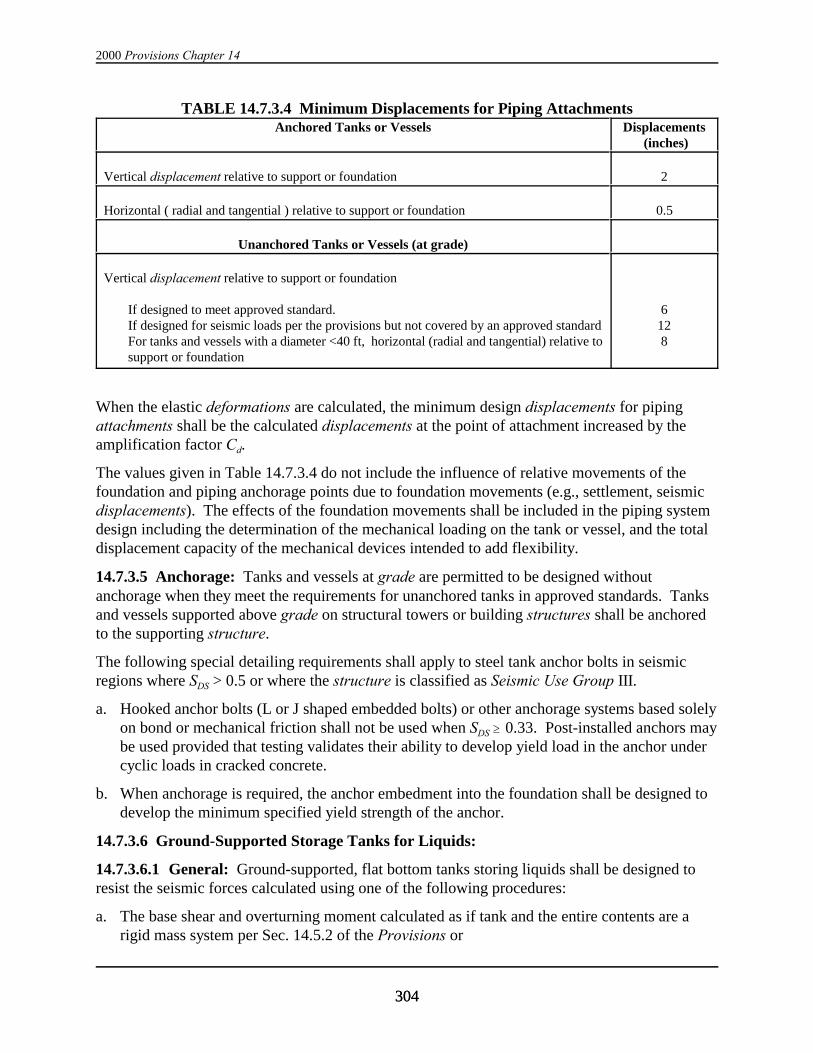
2000 Provisions Chapter 14
304304
TABLE 14.7.3.4 Minimum Displacements for Piping AttachmentsAnchored Tanks or Vessels Displacements
(inches)
Vertical displacement relative to support or foundation 2
Horizontal ( radial and tangential ) relative to support or foundation 0.5
Unanchored Tanks or Vessels (at grade)
Vertical displacement relative to support or foundation
If designed to meet approved standard.If designed for seismic loads per the provisions but not covered by an approved standardFor tanks and vessels with a diameter <40 ft, horizontal (radial and tangential) relative tosupport or foundation
6128
When the elastic deformations are calculated, the minimum design displacements for pipingattachments shall be the calculated displacements at the point of attachment increased by theamplification factor Cd.
The values given in Table 14.7.3.4 do not include the influence of relative movements of thefoundation and piping anchorage points due to foundation movements (e.g., settlement, seismicdisplacements). The effects of the foundation movements shall be included in the piping systemdesign including the determination of the mechanical loading on the tank or vessel, and the totaldisplacement capacity of the mechanical devices intended to add flexibility.
14.7.3.5 Anchorage: Tanks and vessels at grade are permitted to be designed withoutanchorage when they meet the requirements for unanchored tanks in approved standards. Tanksand vessels supported above grade on structural towers or building structures shall be anchoredto the supporting structure.
The following special detailing requirements shall apply to steel tank anchor bolts in seismicregions where SDS > 0.5 or where the structure is classified as Seismic Use Group III.
a. Hooked anchor bolts (L or J shaped embedded bolts) or other anchorage systems based solelyon bond or mechanical friction shall not be used when SDS $ 0.33. Post-installed anchors maybe used provided that testing validates their ability to develop yield load in the anchor undercyclic loads in cracked concrete.
b. When anchorage is required, the anchor embedment into the foundation shall be designed todevelop the minimum specified yield strength of the anchor.
14.7.3.6 Ground-Supported Storage Tanks for Liquids:
14.7.3.6.1 General: Ground-supported, flat bottom tanks storing liquids shall be designed toresist the seismic forces calculated using one of the following procedures:
a. The base shear and overturning moment calculated as if tank and the entire contents are arigid mass system per Sec. 14.5.2 of the Provisions or

Nonbuilding Structures
305305
b. Tanks or vessels storing liquids in Seismic Use Group III or with a diameter greater than 20 ft shall be designed to consider the hydrodynamic pressures of the liquid in determining theequivalent lateral forces and lateral force distribution per the approved standards listed inTable 14.3 and Sec. 14.7.3 of the Provisions.
c. The force and displacement provisions of Sec. 14.5.4 of the Provisions.
The design of tanks storing liquids shall consider the impulsive and convective (sloshing) effectsand consequences on the tank, foundation, and attached elements. The impulsive componentcorresponds to the high frequency amplified response to the lateral ground motion of the tankroof, shell and portion of the contents that moves in unison with the shell. The convectivecomponent corresponds to the low frequency amplified response of the contents in thefundamental sloshing mode. Damping for the convective component shall be 0.5 percent for thesloshing liquid unless otherwise defined by the approved national standard. The followingdefinitions shall apply:
Tc = natural period of the first (convective) mode of sloshing,
Ti = fundamental period of the tank structure and impulsive component of the content,
Tv = natural period of vertical vibration of the liquid and tank structural system,
Vi = base shear due to impulsive component from weight of tank and contents,
Vc = base shear due to the convective component of the effective sloshing mass,
The seismic base shear is the combination of the impulsive and convective components:
V V Vi c= + ( 14.7.3.6.1)
where:
iai i
VS W
R=
cac c
VS W
R=
Sai = the spectral acceleration as a multiplier of gravity including the site impulsivecomponents at period Ti and 5 percent damping.
For Ti < Ts, Sai = SDS.
For Ti > Ts, .aiD
iS
S
T= 1

2000 Provisions Chapter 14
306306
Note: When an approved national standard is used in which the spectral accelerationfor the tank shell, and the impulsive component of the liquid is independent of Ti, thenSai = SDS for all cases.
Sac = the spectral acceleration of the sloshing liquid based on the sloshing period Tc and 0.5percent damping.
For Tc < 4.0 sec, acD
cS
S
T= 115.
For Tc of 4.0 sec or greater, acD
cS
S
T= 1
2
6
and cTD
gH
D
=
2368
368π
. tanh.
where D = the tank diameter in feet, H = liquid height (feet or meters) and g =acceleration due to gravity in consistent units.
Wi = impulsive weight (impulsive component of liquid, roof and equipment, shell, bottom, andinternal components,
Wc = the portion of the liquid weight sloshing.
The general design response spectra for ground-supported liquid storage tanks is shown in Figure14.7.3.6-1.

Nonbuilding Structures
307307
*s ' 0.5DISac (14.7.3.6.1.2)
Design Response Spectra for Ground-Supported Liquid Storage Tanks
Period, T
Sp
ec
tra
l R
es
po
ns
e A
cc
ele
rati
on
, S
a
SDS
SD1
T0 TS
T=
1se
c
T=4
sec
( )%51
== βT
SSai
D
( )%5.05.1 1
== βT
SSac
D
( )%5.06
2
1== β
T
SSac
D
Figure 14.7.3.6-1
14.7.3.6.1.1 Distribution of Hydrodynamic and Inertia Forces: Unless otherwise required bythe appropriate approved standard in Table 14.3, the method given in ACI 350.3 may be used todetermine the vertical and horizontal distribution of the hydrodynamic and inertia forces on thewalls of circular and rectangular tanks.
14.7.3.6.1.2 Freeboard: Sloshing of the liquid within the tank or vessel shall be considered indetermining the freeboard required above the top capacity liquid level. A minimum freeboardshall be provided per Table 14.7.3.6.1.2. The height of the sloshing wave can be estimated by:
TABLE 14.7.3.6.1.2 Minimum Required Freeboard
Value of SDS Seismic Use Group
I II III
SDS < 0.167g a a *sc
0.167g # SDS < 0.33g a a *sc
0.33g # SDS < 0.50g a 0.7*sb *s
c
0.50g # SDS a 0.7*sb *s
c

2000 Provisions Chapter 14
308308
a No minimum freeboard is required.b A freeboard equal to 0.7*s is required unless one of the following alternatives is provided:
1. Secondary containment is provided to control the product spill.2. The roof and supporting structure are designed to contain the sloshing liquid.
c Freeboard equal to the calculated wave height, *s, is required unless one of the following alternatives isprovided:
1. Secondary containment is provided to control the product spill.2. The roof and supporting structure are designed to contain the sloshing liquid.
14.7.3.6.1.3 Equipment and Attached Piping: Equipment, piping, and walkways or otherappurtenances attached to the structure shall be designed to accommodate the displacementsimposed by seismic forces. For piping attachments, see Sec. 14.7.3.4.
14.7.3.6.1.4 Internal Components: The attachments of internal equipment and accessorieswhich are attached to the primary liquid or pressure retaining shell or bottom, or providestructural support for major components (e.g., a column supporting the roof rafters) shall bedesigned for the lateral loads due to the sloshing liquid in addition to the inertial forces. (SeeWozniak and Mitchell, 1978).
14.7.3.6.1.5 Sliding Resistance: The transfer of the total lateral shear force between the tank orvessel and the subgrade shall be considered as follows:
a. For unanchored flat bottom steel tanks, the overall horizontal seismic shear force shall beresisted by friction, Vs, between the tank bottom and the foundation or subgrade. Unanchoredstorage tanks must be designed such that sliding will not occur when the tank is full of storedproduct. The maximum calculated seismic base shear, Vs, shall not exceed W tan 30o (Vs < Wtan 30o).
V shall be determined using the effective weight of the tank, roof and contents after reductionfor coincident vertical earthquake. Lower values of the friction factor should be used if thedesign of bottom to supporting foundation does not justify the friction value above (e.g., leakdetection membrane beneath the bottom with a lower friction factor, smooth bottoms, etc).
b. No additional lateral anchorage is required for anchored steel tanks designed in accordancewith approved standards.
c. The lateral shear transfer behavior for special tank configurations (e.g., shovel bottoms,highly crowned tank bottoms, tanks on grillage) can be unique and are beyond the scope ofthe provisions.
14.7.3.6.1.6 Local Shear Transfer: Local transfer of the shear from the roof to the wall and thewall of the tank into the base shall be considered. For cylindrical tanks and vessels, the peaklocal tangential shear per unit length shall be calculated by:
maxVV
D=
2
π(14.7.3.6.1.6)

Nonbuilding Structures
309309
a. Tangential shear in flat bottom steel tanks shall be transferred through the welded connectionto the steel bottom. This transfer mechanism is deemed acceptable for steel tanks designed inaccordance with the approved standards and Sas < 1.0.
b. For concrete tanks with a sliding base where the lateral shear is resisted by friction betweenthe tank wall and the base, the friction coefficient shall not exceed tan 30o.
c. In fixed-base or hinged-base concrete tanks, the total horizontal seismic base shear is sharedby membrane (tangential) shear and radial shear into the foundation. For anchored flexible-base concrete tanks, the majority of the base shear is resisted by membrane (tangential) shearthrough the anchoring system with only insignificant vertical bending in the wall. Theconnection between the wall and floor shall be designed to resist the maximum tangentialshear.
14.7.3.6.1.7 Pressure Stability: For steel tanks, the internal pressure from the stored productstiffens thin cylindrical shell structural elements subjected to membrane compression forces. This stiffening effect may be considered in resisting seismically induced compressive forces ifpermitted by the approved standard or the building official having jurisdiction.
14.7.3.6.1.8 Shell Support: Steel tanks resting on concrete ring walls or slabs shall have auniformly supported annulus under the shell. Uniform support shall be provided by one of thefollowing methods:
a. Shimming and grouting the annulus,
b. Using fiberboard or other suitable padding
c. Using butt-welded bottom or annular plates resting directly on the foundation,
d. Using closely spaced shims (without structural grout) provided that the localized bearingloads are considered in the tank wall and foundation to prevent local crippling and spalling.
Anchored tanks shall be shimmed and grouted. Local buckling of the steel shell for the peakcompressive force due to operating loads and seismic overturning shall be considered.
14.7.3.6.1.9 Repair, Alteration ,or Reconstruction: Repairs, modifications or reconstruction(i.e., cut down and re-erect) of a tank or vessel shall conform to industry standard practice andthe Provisions. For welded steel tanks storing liquids, see API 653 and the approved nationalstandard in Table 14.3. Tanks that are relocated shall be re-evaluated for the seismic loads forthe new site and the requirements of new construction in accordance with the appropriateapproved national standard and the Provisions.
14.7.3.7 Water and Water Treatment Tanks and Vessels:
14.7.3.7.1 Welded Steel: Welded steel water storage tanks and vessels shall be designed inaccordance with the seismic requirements of AWWA D100 except that the design input forcesshall be modified as follows:
The impulsive and convective components of the base shear are defined by the followingequations for allowable stress design procedures:
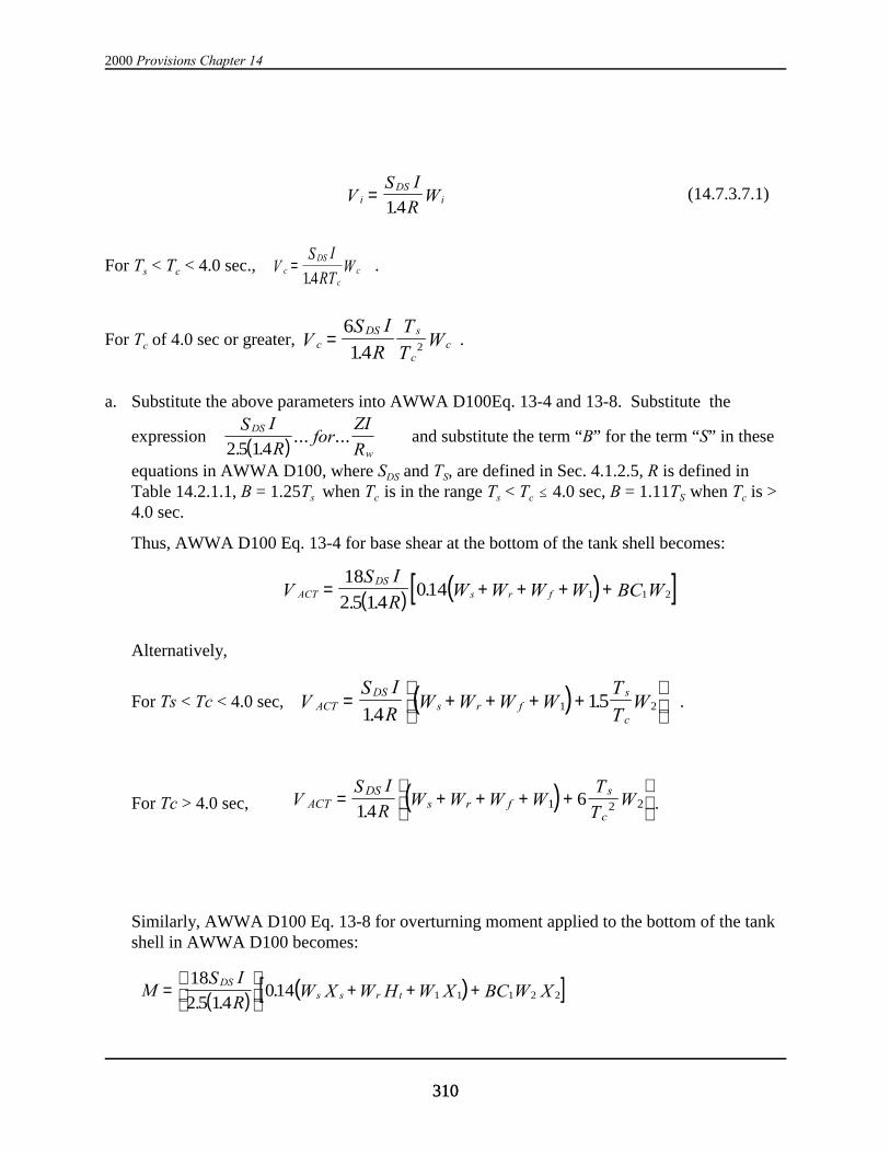
2000 Provisions Chapter 14
310310
iDS
iVS I
RW=
14.(14.7.3.7.1)
For Ts < Tc < 4.0 sec., .cDS
ccV
S I
RTW=
14.
For Tc of 4.0 sec or greater, .cDS s
ccV
S I
R
T
TW=
6
14 2.
a. Substitute the above parameters into AWWA D100Eq. 13-4 and 13-8. Substitute the
expression and substitute the term “B” for the term “S” in these( )DS
w
S I
Rfor
ZI
R2 5 14. .... ...
equations in AWWA D100, where SDS and TS, are defined in Sec. 4.1.2.5, R is defined inTable 14.2.1.1, B = 1.25Ts when Tc is in the range Ts < Tc # 4.0 sec, B = 1.11TS when Tc is >4.0 sec.
Thus, AWWA D100 Eq. 13-4 for base shear at the bottom of the tank shell becomes:
( ) ( )[ ]ACTDS
s r fVS I
RW W W W BC W= + + + +
18
2 5 14014 1 1 2
. ..
Alternatively,
For Ts < Tc < 4.0 sec, .( )ACTDS
s r fs
cV
S I
RW W W W
T
TW= + + + +
14
151 2.
.
For Tc > 4.0 sec, .( )ACTDS
s r fs
cV
S I
RW W W W
T
TW= + + + +
14
61 2 2.
Similarly, AWWA D100 Eq. 13-8 for overturning moment applied to the bottom of the tankshell in AWWA D100 becomes:
( ) ( )[ ]MS I
RW X W H W X BC W X
DSs s r t=
+ + +18
2 5 14014 1 1 1 2 2
. ..
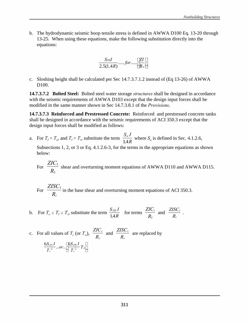
Nonbuilding Structures
311311
b. The hydrodynamic seismic hoop tensile stress is defined in AWWA D100 Eq. 13-20 through13-25. When using these equations, make the following substitution directly into theequations:
c. Sloshing height shall be calculated per Sec 14.7.3.7.1.2 instead of (Eq 13-26) of AWWAD100.
14.7.3.7.2 Bolted Steel: Bolted steel water storage structures shall be designed in accordancewith the seismic requirements of AWWA D103 except that the design input forces shall bemodified in the same manner shown in Sec 14.7.3.8.1 of the Provisions.
14.7.3.7.3 Reinforced and Prestressed Concrete: Reinforced and prestressed concrete tanksshall be designed in accordance with the seismic requirements of ACI 350.3 except that thedesign input forces shall be modified as follows:
a. For TI < To, and TI > Ts, substitute the term where Sa is defined in Sec. 4.1.2.6,aS I
R14.Subsections 1, 2, or 3 or Eq. 4.1.2.6-3, for the terms in the appropriate equations as shownbelow:
For shear and overturning moment equations of AWWA D110 and AWWA D115.1
1
ZIC
R
For in the base shear and overturning moment equations of ACI 350.3. 1ZISC
Ri
b. For To # TI # Ts, substitute the term for terms and .DSS I
R14.iZIC
R1
i
i
ZISC
R
c. For all values of Tc (or Tw), and are replaced byc
c
ZIC
Rc
c
ZISC
R
D
c
DS
cS
S I
Tor
S I
TT
1
2 2
6 6.. ..
w
DS
R
ZIfor
R
IS..........
)4.1(5.2
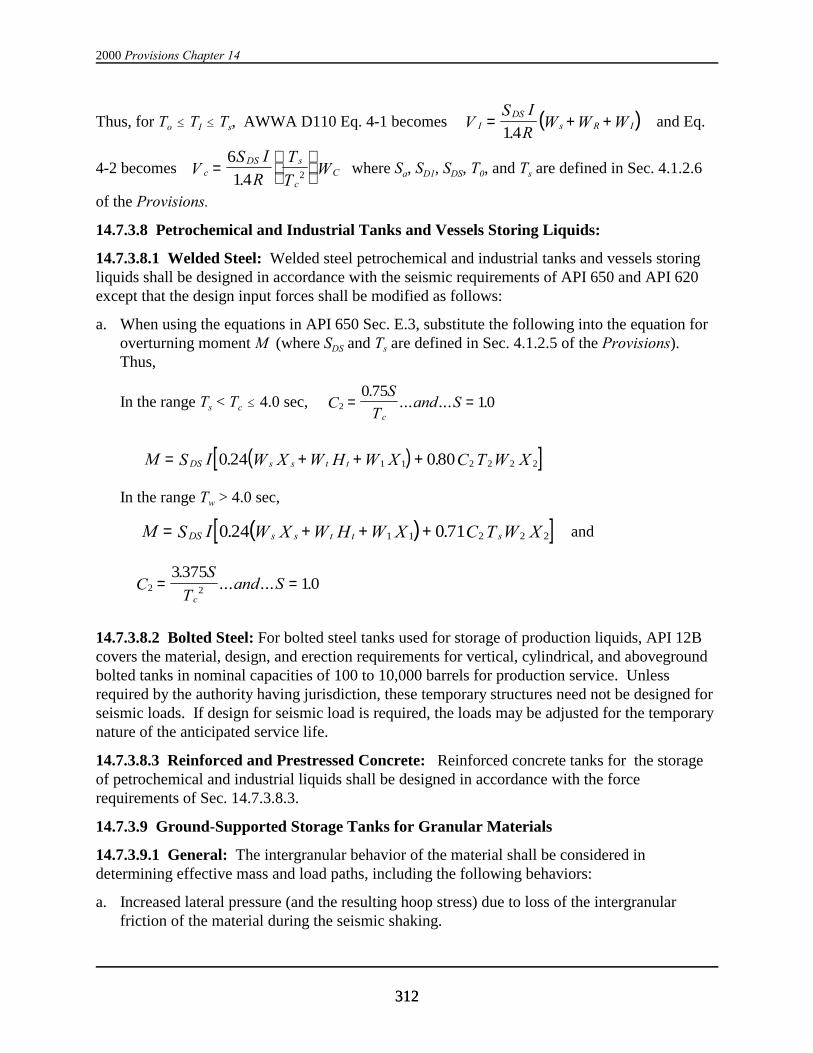
2000 Provisions Chapter 14
312312
Thus, for To # TI # Ts, AWWA D110 Eq. 4-1 becomes and Eq.( )IDS
s R IVS I
RW W W= + +
14.
4-2 becomes where Sa, SD1, SDS, T0, and Ts are defined in Sec. 4.1.2.6cDS s
cCV
S I
R
T
TW=
6
14 2.of the Provisions.
14.7.3.8 Petrochemical and Industrial Tanks and Vessels Storing Liquids:
14.7.3.8.1 Welded Steel: Welded steel petrochemical and industrial tanks and vessels storingliquids shall be designed in accordance with the seismic requirements of API 650 and API 620except that the design input forces shall be modified as follows:
a. When using the equations in API 650 Sec. E.3, substitute the following into the equation foroverturning moment M (where SDS and Ts are defined in Sec. 4.1.2.5 of the Provisions). Thus,
In the range Ts < Tc # 4.0 sec, 2
0 7510C
S
Tand S
c
= =.
... ... .
( )[ ]M S I W X W H W X C T W XDS s s t t= + + +0 24 0801 1 2 2 2 2. .
In the range Tw > 4.0 sec,
and ( )[ ]M S I W X W H W X C T W XDS s s t t s= + + +0 24 0 711 1 2 2 2. .
2 2
337510C
S
Tand S
c
= =.
... ... .
14.7.3.8.2 Bolted Steel: For bolted steel tanks used for storage of production liquids, API 12Bcovers the material, design, and erection requirements for vertical, cylindrical, and abovegroundbolted tanks in nominal capacities of 100 to 10,000 barrels for production service. Unlessrequired by the authority having jurisdiction, these temporary structures need not be designed forseismic loads. If design for seismic load is required, the loads may be adjusted for the temporarynature of the anticipated service life.
14.7.3.8.3 Reinforced and Prestressed Concrete: Reinforced concrete tanks for the storageof petrochemical and industrial liquids shall be designed in accordance with the forcerequirements of Sec. 14.7.3.8.3.
14.7.3.9 Ground-Supported Storage Tanks for Granular Materials
14.7.3.9.1 General: The intergranular behavior of the material shall be considered indetermining effective mass and load paths, including the following behaviors:
a. Increased lateral pressure (and the resulting hoop stress) due to loss of the intergranularfriction of the material during the seismic shaking.
Nonbuilding Structures
313313
b. Increased hoop stresses generated from temperature changes in the shell after the materialhas been compacted.
c. Intergranular friction which can transfer seismic shear directly to the foundation.
14.7.3.9.2 Lateral Force Determination: The lateral forces for tanks and vessels storinggranular materials at grade shall be determined by the requirements and accelerations for shortperiod structures (i.e., Sas).
14.7.3.9.3 Force Distribution to Shell and Foundation:
14.7.3.9.3.1 Increased Lateral Pressure: The increase in lateral pressure on the tank wall shallbe added to the static design lateral pressure but shall not be used in the determination ofpressure stability effects on the axial buckling strength of the tank shell.
14.7.3.9.3.2 Effective Mass: A portion of a stored granular mass will acts with the shell (theeffective mass). The effective mass is related to the physical characteristics of the product, theheight-to-diameter (H/D) ratio of the tank and the intensity of the seismic event. The effectivemass shall be used to determine the shear and overturning loads resisted by the tank.
14.7.3.9.3.3 Effective Density: The effective density factor (that part of the total stored massof product which is accelerated by the seismic event) shall be determined in accordance ACI 313.
14.7.3.9.3.4 Lateral Sliding: For granular storage tanks that have a steel bottom and aresupported such that friction at the bottom to foundation interface can resist lateral shear loads, noadditional anchorage to prevent sliding is required. For tanks without steel bottoms (i.e., thematerial rests directly on the foundation), shear anchorage shall be provided to prevent sliding.
14.7.3.9.3.5 Combined Anchorage Systems: If separate anchorage systems are used to preventoverturning and sliding, the relative stiffness of the systems shall be considered in determiningthe load distribution.
14.7.3.9.4 Welded Steel Structures: Welded steel granular storage structures shall be designedfor Chapter 4 of the Provisions. Component allowable stresses and materials shall be perAWWA D100 except the allowable circumferential membrane stresses and materialrequirements in API 650 shall apply.
14.7.3.9.5 Bolted Steel Structures: Bolted steel granular storage structures shall be designed incompliance with Chapter 4 of the Provisions. Component allowable stresses and materials shallbe per AWWA D103.
14.7.3.9.6 Reinforced Concrete Structures: Reinforced concrete structures for the storage ofgranular materials shall be designed in accordance with the force requirements of Chapter 4 ofthe Provisions and the requirements of ACI 313.
14.7.3.9.7 Prestressed Concrete Structures: Prestressed concrete structures for the storage ofgranular materials shall be designed in accordance with the force provisions of Chapter 4 of theProvisions and the requirements of ACI 313.
14.7.3.10 Elevated Tanks and Vessels for Liquids and Granular Materials:
2000 Provisions Chapter 14
314314
14.7.3.10.1 General: This section applies to tanks, vessels, bins, and hoppers that are elevatedabove grade where the supporting tower is an integral part of the structure or where the primaryfunction of the tower is to support the tank or vessel. Tanks and vessels that are supported withinbuildings, or are incidental to the primary function of the tower are considered mechanicalequipment and shall be designed in accordance with Chapter 6 of the Provisions.
Elevated tanks shall be designed for the force and displacement requirements of the applicableapproved standard, or Sec 14.5.
14.7.3.10.2 Effective mass: The design of the supporting tower or pedestal, anchorage, andfoundation for seismic overturning shall assume the material stored is a rigid mass acting at thevolumetric center of gravity. The effects of fluid-structure interaction may be considered indetermining the forces, effective period, and mass centroids of the system if the followingrequirements are met:
a. The sloshing period, Tc is greater than 3T where T = natural period of the tank with confinedliquid (rigid mass) and supporting structure.
b. The sloshing mechanism (i.e., the percentage of convective mass and centroid) is determinedfor the specific configuration of the container by detailed fluid structure interaction analysisor testing.
Soil-structure interaction may be included in determining T providing the provisions of Sec 2.5are met.
14.7.3.10.3 P-Delta effects: The lateral drift of the elevated tank shall be considered as follows:
a. The design drift, the elastic lateral displacement of the stored mass center of gravity shall beincreased by the factor Cd for evaluating the additional load in the support structure.
b. The base of the tank shall be assumed to be fixed rotationally and laterally
c. Deflections due to bending, axial tension or compression shall be considered. For pedestaltanks with a height to diameter ratio less than 5, shear deformations of the pedestal shall beconsidered.
d. The dead load effects of roof mounted equipment or platforms shall be included in theanalysis.
e. If constructed within the plumbness tolerances specified by the approved standard, initial tiltneed not be considered in the P-delta analysis.
14.7.3.10.4 Transfer of Lateral Forces into Support Tower: For post supported tanks andvessels that are cross braced:
a. The bracing shall be installed in such a manner as to provide uniform resistance to the lateralload (e.g., pretensioning or tuning to attain equal sag).
b. The additional load in the brace due to the eccentricity between the post to tank attachmentand the line of action of the bracing shall be included.
Nonbuilding Structures
315315
c. Eccentricity of compression strut line of action (elements that resist the tensile pull from thebracing rods in the lateral force resisting systems) with their attachment points shall beconsidered.
d. The connection of the post or leg with the foundation shall be designed to resist both thevertical and lateral resultant from the yield load in the bracing assuming the direction of thelateral load is oriented to produce the maximum lateral shear at the post to foundationinterface. Where multiple rods are connected to the same location, the anchorage shall bedesigned to resist the concurrent tensile loads in the braces.
14.7.3.10.5 Evaluation of Structures Sensitive to Buckling Failure: Shell structures thatsupport substantial loads may exhibit a primary mode of failure from localized or generalbuckling of the support pedestal or skirt during seismic loads. Such structures may includesingle pedestal water towers, skirt supported process vessels, and similar single member towers. Where the structural assessment concludes that buckling of the support is the governing primarymode of failure, structures and components in Seismic Use Group III shall be designed to resistthe seismic forces as follows:
a. The seismic response coefficient for this evaluation shall be per Sec 5.3.2.1 of the Provisionswith I/R set equal to 1.0. Soil-structure and fluid-structure interaction may be utilized indetermining the structural response. Vertical or orthogonal combinations need not beconsidered.
b. The resistance of the structure or component shall be defined as the critical bucklingresistance of the element (i.e. a factor of safety set equal to 1.0).
c. The anchorage and foundation shall be designed to resist the load determined in item a. Thefoundation shall be proportioned to provide a stability ratio of 1.2 for the overturningmoment. The maximum toe pressure under the foundation shall not exceed the ultimatebearing capacity or the lesser of 3 times the allowable bearing capacity. All structuralcomponents and elements of the foundation shall be designed to resist the combined loadswith a load factor of 1.0 on all loads, including dead load, live load and earthquake load.Anchors shall be permitted to yield.
14.7.3.10.6 Welded Steel Water Storage Structures: Welded steel elevated water storagestructures shall be designed and detailed in accordance with the seismic requirements of AWWAD100 and the Provisions except that the design input forces shall be modified by substituting the
following terms for in AWWA D100 Eq.13-1 and 13-3 of and set the value for S = 1.0.ZIC
Rw
For T < Ts, substitute the term .DSS I
R14.
For Ts < T < 4.0 sec, substitute the term .( )DS I
T R1
14.
2000 Provisions Chapter 14
316316
For T > 4.0 sec, substitute the term .( )DS I
T R1
2 14.
14.7.3.10.6.1 Analysis Procedures: The equivalent lateral force procedure may be used. Amore rigorous analysis shall be permitted. Analysis of single pedestal structures shall be basedon a fixed-base, single-degree-of-freedom model. All mass, including the liquid, shall beconsidered rigid unless the sloshing mechanism (i.e., the percentage of convective mass andcentroid) is determined for the specific configuration of the container by detailed fluid structureinteraction analysis or testing. Soil-structure interaction may be included.
14.7.3.10.6.2 Structure Period: The fundamental period of vibration of the structure shall beestablished using the structural properties and deformational characteristics of the resistingelements in a substantiated analysis. The period used to calculate the seismic responsecoefficient shall not exceed 4.0 sec. See AWWA D100 for guidance on computing thefundamental period of cross braced structures.
14.7.3.10.7 Concrete Pedestal (Composite) Tanks: Concrete pedestal (composite) elevatedwater storage structures shall be designed in accordance with the requirements of ACI 371 except that the design input forces shall be modified as follows:
In ACI 371 Eq. 4-8a:
For Ts < T < 4.0 sec, substitute the term forDS I
TR1 vC
RT
122 3
.
For T > 4.0 sec, substitute the term for DS I
T R1
2
4 vC
R T
122 3
.
In ACI 371 Eq. 4-8b, substitute the term for DSS I
RaC
R
2 5.
In ACI 371 Eq. 4-9, substitute the term 0.2SDS for 0.5Ca.
14.7.3.10.7.1 Analysis Procedures: The equivalent lateral force procedure may be used for allstructures and shall be based on a fixed-base, single-degree-of-freedom model. All mass,including the liquid, shall be considered rigid unless the sloshing mechanism (i.e., the percentageof convective mass and centroid) is determined for the specific configuration of the container bydetailed fluid structure interaction analysis or testing. Soil-structure interaction may be included.A more rigorous analysis is permitted.
14.7.3.10.7.2 Structure Period: The fundamental period of vibration of the structure shall beestablished using the uncracked structural properties and deformational characteristics of theresisting elements in a properly substantiated analysis. The period used to calculate the seismicresponse coefficient shall not exceed 2.5 sec.
14.7.3.11 Boilers and Pressure Vessels:

Nonbuilding Structures
317317
14.7.3.11.1 General: Attachments to the pressure boundary, supports, and lateral force resistinganchorage systems for boilers and pressure vessels shall be designed to meet the force anddisplacement requirements of Sec 3.1.3 and 3.1.4 and the additional requirements of this section. Boilers and pressure vessels categorized as Seismic Use Group II or III shall be designed to meetthe force and displacement requirements of Sec 3.1.3 and 3.1.4.
14.7.3.11.2 ASME Boilers and Pressure Vessels: Boilers or pressure vessels designed andconstructed in accordance with ASME shall be deemed to meet the requirements of this sectionprovided that the displacement requirements of Sec 3.1.3 and 3.1.4 are used with appropriatescaling of the force and displacement requirements to the working stress design basis.
14.7.3.11.3 Attachments of Internal Equipment and Refractory: Attachments to the pressureboundary for internal and external ancillary components (e.g., refractory, cyclones, trays) shall bedesigned to resist the seismic forces in the Provisions to safeguard against rupture of the pressureboundary. Alternatively, the element attached may be designed to fail prior to damaging thepressure boundary provided that the consequences of the failure does not place the pressureboundary in jeopardy. For boilers or vessels containing liquids, the effect of sloshing on theinternal equipment shall be considered if the equipment can damage the integrity of the pressureboundary.
14.7.3.11.4 Coupling of Vessel and Support Structure: Where the mass of the operatingvessel or vessels supported is greater than 25 percent of the total mass of the combined structure,the coupling of the masses shall be considered. Coupling with adjacent, connected structuressuch as multiple towers shall be considered if the structures are interconnected with elementsthat will transfer loads from one structure to the other.
14.7.3.11.5 Effective Mass: Fluid-structure interaction (sloshing) shall be considered indetermining the effective mass of the stored material providing sufficient liquid surface exists forsloshing to occur and the Tc is greater than 3T. Changes to or variations in material density withpressure and temperature shall be considered.
14.7.3.11.6 Other Boilers and Pressure Vessels: Boilers and pressure vessels that aredesignated Seismic Use Group III but are not designed and constructed in accordance with therequirements of ASME shall meet the following requirements:
The seismic loads in combination with other service loads and appropriate environmental effectsshall not exceed the material strength shown in Table 14.7.3.11.6.
TABLE 14.7.3.11.6 Maximum Material Strength
Material
MinimumRatioFu/Fy
Max MaterialStrengthVessel Material
Max MaterialStrengthThreaded Materiala
Ductile (e.g., steel, aluminum,copper) 1.33 b 90% 70%Semi-ductile 1.2 c 70% 50%Nonductile (e.g., cast iron, ceramics,fiberglass) NA 25% 20%a Threaded connection to vessel or support system.b Minimum 20% elongation per the ASTM material specification.
2000 Provisions Chapter 14
318318
c Minimum 15% elongation per the ASTM material specification.
Consideration shall be made to mitigate seismic impact loads for boiler or vessel componentsconstructed of nonductile materials or vessels operated in such a way that material ductility isreduced (e.g., low temperature applications).
14.7.3.11.7 Supports and Attachments for Boilers and Pressure Vessels: Attachments to thepressure boundary and support for boilers and pressure vessels shall meet the followingrequirements:
a. Attachments and supports transferring seismic loads shall be constructed of ductile materialssuitable for the intended application and environmental conditions.
b. Seismic anchorages embedded in concrete shall be ductile and detailed for cyclic loads.
c. Seismic supports and attachments to structures shall be designed and constructed so that thesupport or attachment remains ductile throughout the range of reversing seismic lateral loadsand displacements.
d. Vessel attachments shall consider the potential effect on the vessel and the support foruneven vertical reactions based on variations in relative stiffness of the support members,dissimilar details, non-uniform shimming or irregular supports. Uneven distribution oflateral forces shall consider the relative distribution of the resisting elements, the behavior ofthe connection details, and vessel shear distribution.
The requirements of Sec.14.5 and 14.7.3.10.5 shall also be applicable to this section.
14.7.3.12 Liquid and Gas Spheres:
14.7.3.12.1 General: Attachments to the pressure or liquid boundary, supports, and lateral forceresisting anchorage systems for liquid and gas spheres shall be designed to meet the force anddisplacement requirements of Sec 3.1.3 and 3.1.4 and the additional requirements of this section.Spheres categorized as Seismic Use Group II or III shall themselves be designed to meet the forceand displacement requirements of Sec 3.1.3 and 3.1.4.
14.7.3.12.2 ASME Spheres: Spheres designed and constructed in accordance with DivisionVIII of ASME shall be deemed to meet the requirements of this section providing thedisplacement requirements of Sec 3.1.3 and 3.1.4 are used with appropriate scaling of the forceand displacement requirements to the working stress design basis.
14.7.3.12.3 Attachments of Internal Equipment and Refractory: Attachments to the pressureor liquid boundary for internal and external ancillary components (e.g., refractory, cyclones,trays) shall be designed to resist the seismic forces in the Provisions to safeguard against ruptureof the pressure boundary. Alternatively, the element attached to the sphere could be designed tofail prior to damaging the pressure or liquid boundary providing the consequences of the failuredo not place the pressure boundary in jeopardy. For spheres containing liquids, the effect ofsloshing on the internal equipment shall be considered if the equipment can damage the pressureboundary.
Nonbuilding Structures
319319
14.7.3.12.4 Effective Mass: Fluid-structure interaction (sloshing) shall be considered indetermining the effective mass of the stored material providing sufficient liquid surface exists forsloshing to occur and the Tc is greater than 3T. Changes to or variations in fluid density shall beconsidered.
14.7.3.12.5 Post- and Rod- Supported: For post-supported spheres that are cross braced:
a. The requirements of Sec. 14.7.3.10.4 shall also be applicable to this section.
b. The stiffening effect of (reduction in lateral drift) from pretensioning of the bracing shall beconsidered in determining the natural period.
c. The slenderness and local buckling of the posts shall be considered.
d. Local buckling of the sphere shell at the post attachment shall be considered.
e. For spheres storing liquids, bracing connections shall be designed and constructed to developthe minimum published yield strength of the brace. For spheres storing gas vapors only,bracing connection shall be designed for Wo times the maximum design load in the brace.Lateral bracing connections directly attached to the pressure or liquid boundary areprohibited.
14.7.3.12.6 Skirt Supported: For skirt-supported spheres, the following requirements shallapply:
a. The provisions of Sec. 14.7.3.10.5 also shall apply.
b. The local buckling of the skirt under compressive membrane forces due to axial load andbending moments shall be considered.
c. Penetration of the skirt support (e.g., manholes, piping) shall be designed and constructed tomaintain the strength of the skirt without penetrations.
14.7.3.13 Refrigerated Gas Liquid Storage Tanks and Vessels:
14.7.3.13.1 General: The seismic design of the tanks and facilities for the storage of liquefiedhydrocarbons and refrigerated liquids is beyond the scope of this section. The design of suchtanks is addressed in part by various approved standards as listed in Table 14.3.
Exception: Low pressure, welded steel storage tanks for liquefied hydrocarbon gas(e.g., LPG, butane) and refrigerated liquids (e.g., ammonia) could be designed inaccordance with the requirements of Sec. 14.7.3.8 and API 620.
14.7.3.14 Horizontal, Saddle-Supported Vessels for Liquid or Vapor Storage:
14.7.3.14.1 General: Horizontal vessels supported on saddles (sometimes referred to asblimps) shall be designed to meet the force and displacement requirements of Sec 3.1.3 and3.1.4.
14.7.3.14.2 Effective mass: Changes to or variations in material density shall be considered. The design of the supports, saddles, anchorage, and foundation for seismic overturning shallassume the material stored is a rigid mass acting at the volumetric center of gravity.
2000 Provisions Chapter 14
320320
14.7.3.14.3 Vessel Design: Unless a more rigorous analysis is performed, vessels shall bedesigned as follows:
a. Horizontal vessels with a length to diameter ratio of 6 or more may be assumed to be asimply supported beam spanning between the saddles for determining the natural period ofvibration and global bending moment.
b. Horizontal vessels with a length to diameter ratio of less than 6, the effects of “deep beamshear” shall be considered when determining the fundamental period and stressdistribution.
c. Local bending and buckling of the vessel shell at the saddle supports due to seismic loadshall be considered. The stabilizing effects of internal pressure shall not be considered toincrease the buckling resistance of the vessel shell.
d. If the vessel is a combination of liquid and gas storage, the vessel and supports shall bedesigned both with and without gas pressure acting (assume piping has ruptured andpressure does not exist).
14.7.4 Stacks and Chimneys:
14.7.4.1 General: Stacks and chimneys are permitted to be either lined or unlined, and shallconstructed from concrete, steel, or masonry.
14.7.4.2 Design Basis: Steel stacks, concrete stacks, steel chimneys, concrete chimneys, andliners shall be designed to resist seismic lateral forces determined from a substantiatedanalysis using approved standards. Interaction of the stack or chimney with the liners shall beconsidered. A minimum separation shall be provided between the liner and chimney equal toCd times the calculated differential lateral drift.
14.7.5 Amusement Structures:
14.7.5.1 General: Amusement structures are permanently fixed structures constructedprimarily for the conveyance and entertainment of people.
14.7.5.2 Design Basis: Amusement structures shall be designed to resist seismic lateralforces determined from a substantiated analysis using approved standards.
14.7.6 Special Hydraulic Structures:
14.7.6.1 General: Special hydraulic structures are structures that are contained inside liquidcontaining structures. These structures are exposed to liquids on both wall surfaces at thesame head elevation under normal operating conditions. Special hydraulic structures aresubjected to out of plane forces only during an earthquake when the structure is subjected todifferential hydrodynamic fluid forces. Examples of special hydraulic structures include separation walls, baffle walls, weirs, and other similar structures.
14.7.6.2 Design Basis: Special hydraulic structures shall be designed for out-of-phasemovement of the fluid. Unbalanced forces from the motion of the liquid must be appliedsimultaneously "in front of" and "behind" these elements.
Nonbuilding Structures
321321
Structures subject to hydrodynamic pressures induced by earthquakes shall be designed forrigid body and sloshing liquid forces and their own inertia force. The height of sloshing shallbe determined and compared to the freeboard height of the structure.
Interior elements, such as baffles or roof supports, also shall be designed for the effects ofunbalanced forces and sloshing.
14.7.7 Secondary Containment Systems:
14.7.7.1 General: Secondary containment systems such as impoundment dikes and wallsshall meet the requirements of the applicable standards for tanks and vessels and the authorityhaving jurisdiction.
Secondary containment systems shall be designed to withstand the effects of a maximumconsidered earthquake when empty and a maximum considered earthquake when fullincluding all hydrodynamic forces.
14.7.7.2 Freeboard: Sloshing of the liquid within the secondary containment area shall beconsidered in determining the height of the impound. A minimum freeboard Sec 14.7.3.6.1.2,*s, shall be provided when:
s acDSδ = 050. (14.7.7.2)
where Sac is determined per Sec. 14.7.3.6.1. For circular impoundment dikes, D shall be thediameter of the impoundment. For rectangular impoundment dikes, D shall be the longerlongitudinal plan dimension.
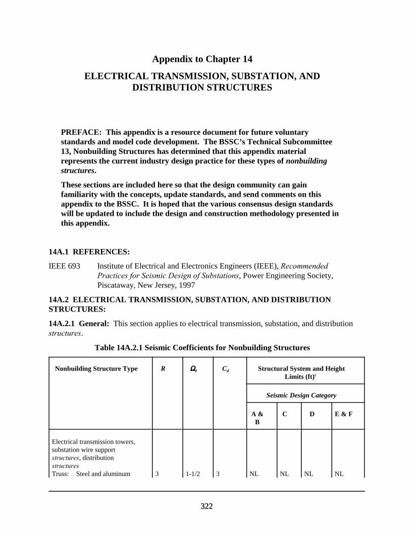
322322
Appendix to Chapter 14
ELECTRICAL TRANSMISSION, SUBSTATION, ANDDISTRIBUTION STRUCTURES
PREFACE: This appendix is a resource document for future voluntarystandards and model code development. The BSSC’s Technical Subcommittee13, Nonbuilding Structures has determined that this appendix materialrepresents the current industry design practice for these types of nonbuildingstructures.
These sections are included here so that the design community can gainfamiliarity with the concepts, update standards, and send comments on thisappendix to the BSSC. It is hoped that the various consensus design standardswill be updated to include the design and construction methodology presented inthis appendix.
14A.1 REFERENCES:
IEEE 693 Institute of Electrical and Electronics Engineers (IEEE), RecommendedPractices for Seismic Design of Substations, Power Engineering Society,Piscataway, New Jersey, 1997
14A.2 ELECTRICAL TRANSMISSION, SUBSTATION, AND DISTRIBUTIONSTRUCTURES:
14A.2.1 General: This section applies to electrical transmission, substation, and distributionstructures.
Table 14A.2.1 Seismic Coefficients for Nonbuilding Structures
Nonbuilding Structure Type R SSSS0 Cd Structural System and HeightLimits (ft)c
Seismic Design Category
A &B
C D E & F
Electrical transmission towers,substation wire supportstructures, distributionstructuresTruss: Steel and aluminum 3 1-1/2 3 NL NL NL NL
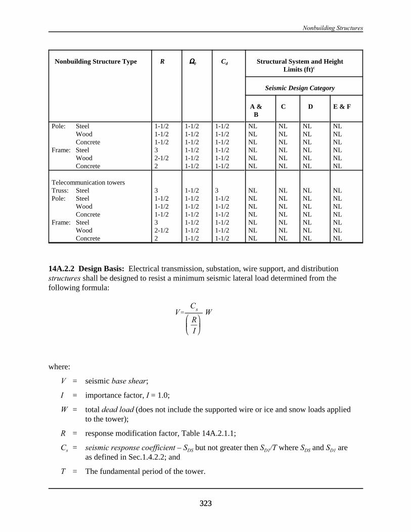
Nonbuilding Structures
Nonbuilding Structure Type R SSSS0 Cd Structural System and HeightLimits (ft)c
Seismic Design Category
A &B
C D E & F
323323
Pole: SteelWoodConcrete
Frame: SteelWoodConcrete
1-1/21-1/21-1/232-1/22
1-1/21-1/21-1/21-1/21-1/21-1/2
1-1/21-1/21-1/21-1/21-1/21-1/2
NLNLNLNLNLNL
NLNLNLNLNLNL
NLNLNLNLNLNL
NLNLNLNLNLNL
Telecommunication towersTruss: Steel Pole: Steel
WoodConcrete
Frame: SteelWoodConcrete
31-1/21-1/21-1/232-1/22
1-1/21-1/21-1/21-1/21-1/21-1/21-1/2
31-1/21-1/21-1/21-1/21-1/21-1/2
NLNLNLNLNLNLNL
NLNLNLNLNLNLNL
NLNLNLNLNLNLNL
NLNLNLNLNLNLNL
14A.2.2 Design Basis: Electrical transmission, substation, wire support, and distributionstructures shall be designed to resist a minimum seismic lateral load determined from thefollowing formula:
V'Cs
RI
W
where:
V = seismic base shear;
I = importance factor, I = 1.0;
W = total dead load (does not include the supported wire or ice and snow loads appliedto the tower);
R = response modification factor, Table 14A.2.1.1;
Cs = seismic response coefficient – SDS but not greater then SD1/T where SDS and SD1 areas defined in Sec.1.4.2.2; and
T = The fundamental period of the tower.

1997 Provision Appendix to Chapter 14
324324
A simplified static analysis and applying the seismic base shear (times a load factor of 1.0) atthe center of mass of the structure can be used to determine if seismic load controls thedesign. The lateral force shall be evaluated in both the longitudinal and transverse directionsto the support wire. When it is determined that seismic loads are significant (control thedesign of main load carrying members), a more detailed lateral force distribution shall beperformed per Sec. 14.2.1 (with k = 1) of the Provisions and/or a modal analysis as specifiedby Sec. A.1.5 of IEEE 693.
Seismic lateral loads and design criteria for substation equipment support structures shall bein accordance with the requirements of IEEE 693. The design, manufacture, and inspectionshall be in accordance with the quality control and quality assurance requirements of theindustry design standards and recommended practices specified in Sec. 14.1.9.
14A.3 TELECOMMUNICATION TOWERS:
14A.3.1 General: This section applies to telecommunication towers.
14A.3.2 Design Basis: Self-supporting telecommunication towers shall be designed to resista minimum seismic lateral force determined from the following formula:
VCR
I
Ws=
(14A.5.2)
where:
V = seismic base shear;
I = importance factor, Table 14.2.1.2;
W = total dead load (including all attachments);
R = response modification factor, Table 14A.2.1.1; and
Cs = seismic response coefficient – SDS but not greater then SD1/T where SD1 and SDS, areas defined in Sec. 4.2.2 and T is the fundamental period of the tower
A simplified static analysis applying the lateral load (times a load factor of 1.0) at the center ofmass of the tower can be used to determine if seismic load controls the design of self-supporting towers. When it is determined that seismic loads are significant (control the designof main load carrying members), a more detailed lateral force distribution (with k = 1) andanalysis shall be performed per Sec. 14.2.1 of the Provisions.
The lateral force applied to a telecommunication tower supported on a structure shouldaccount for the base motion input amplification as a result of the building earthquake response(see Sec. 14.1.2 of the Provisions). Guyed towers require a more detailed computer analysisincluding nonlinear analysis and guy-tower interaction effects. An industry accepted modalanalysis procedure should be used for guyed towers.

Nonbuilding Structures
325325
The design, manufacture, and inspection shall be in accordance with the quality control andquality assurance requirements of the industry design standards and recommended practicesspecified in Sec. 14.1.9.
14A.4 BURIED STRUCTURES:
14A.4.1 General: Buried structures are subgrade structures such as tanks, tunnels, andpipes. Buried structures that are designated as Seismic Use Group II or III or are of such asize or length to warrant special seismic design as determined by the registered designprofessional shall be identified in the geotechnical report.
14A.4.2 Design Basis: Buried structures shall be designed to resist minimum seismic lateralforces determined from a substantiated analysis using approved procedures. Flexiblecouplings shall be provided for buried structures requiring special seismic considerationswhere changes in the support system, configuration, or soil condition occur.
14A.5 PERFORMANCE CRITERIA FOR TANKS AND VESSELS: Tanks and vesselsshall be designed to meet the following minimum post-earthquake performance criteria. These criteria depend on the Seismic Use Group (category) classification and content-relatedhazards of the tanks and vessels being considered:
TABLE 14A.5 Performance Criteria for Tanks and Vessels
PerformanceCategorya
Minimum Post-Earthquake Performance
Ib The structure shall be permitted to fail provided the resulting spill does notpose a threat to the public or to adjoining Category I, II or III structures.
II The structure shall be permitted to sustain localized damage, includingminor leaks, provided (a) such damage remains localized and does notpropagate; and (b) the resulting leakage does not pose a threat to thepublic or to adjoining Category I, II or III structures.
III The structure shall be permitted to sustain minor damage, and itsoperational systems or components (valves and controls) shall be permittedto become inoperative, provided that (a) the structure retains its ability tocontain 100% of its contents; and (b) the structure’s minor damage, and thefailure of its operational systems or components, are not accompanied by,or lead to, leakage.
IV The structure shall be permitted to sustain minor damage provided that (a)it shall retain its ability to contain 100% of its contents without leakage;and (b) its operational systems or components shall remain fullyoperational.
a Performance Categories I, II, and III correspond to the Seismic Use Groups defined in Sec.1.3 and tabulated in Tables 14.2.1.2 and 14.7.3.7.1.2.
b For tanks and vessels in Performance Category IV, an Importance Factor I = 1.0 shall beused.
327
Appendix A
DIFFERENCES BETWEEN THE 1997 AND THE 2000 EDITIONS OFTHE NEHRP RECOMMENDED PROVISIONS
EDITORIAL AND ORGANIZATIONAL CHANGES
For the 2000 Provisions, an editorial change has been made to the format used to cite referencedocuments. In the past, reference documents generally were listed at the beginning of a chapterand identified as Ref. X-1, Ref. X-2, etc., with the “X” being the chapter number. The references then were cited in the chapter using the “Ref. X-1” format. In the 2000 Provisions, the referencedocuments continue to be listed at the beginning of a chapter with an indication of the edition tobe used but are presented with an abbreviated designation that is used to cite the reference in thetext of the chapter (e.g., ACI 318).
2000 CHAPTER 1, GENERAL PROVISIONS
In the 1997 Provisions, one-and two-story wood frame dwellings were exempted from theseismic requirements if the design spectral response acceleration at short periods was less than0.4g. For the 2000 Provisions, these dwellings are exempted from all Provisions requirements ifthey are in Seismic Design Categories A, B, or C. They also are exempted from the remainingrequirements in the Provisions if they are designed and constructed in accordance with theconventional light frame construction requirements in Sec. 12.5.
In Sec.1.2.4, alterations that increase the seismic force in any existing structural element by morethen 5 percent or decrease the design strength of any existing structural element to resist seismicforces by more than 5 percent are not permitted unless the entire seismic-force-resisting system isdetermined to conform to the Provisions for a new structure. All alterations are required toconform to the Provisions for a new structure. Excepted from these requirements are alterationsto existing structural elements or additions of new structural elements that are not required by theProvisions but are initiated to increase the strength or stiffness of the seismic-force-resistingsystem of an existing structure provided an engineering analysis meeting several specificallystated requirements is submitted.
2000 CHAPTER 2, GLOSSARY AND NOTATIONS
Additions and deletions have been made to reflect changes made in the text of the Provisions.
2000 CHAPTER 3, QUALITY ASSURANCE
For the 2000 Provisions, several inspection-related changes have been made. One is arequirement for periodic inspection of shear walls with structural wood and the second requires
2000 Provisions, Appendix A
328
periodic special inspection of architectural components (glass). The special inspectionrequirements also have been modified to exempt nonbearing metal stud and gypsum boardpartitions from periodic special inspection; however, interior and exterior veneers are nowcovered with exceptions pertaining to lightweight partitions.
Sec. 3.6, Reporting and Compliance Procedures, also has been modified to more clearly statewho is to receive reports.
2000 CHAPTER 4, GROUND MOTION
The only substantive changes made for the 2000 Provisions relate to the exception in Sec. 4.1.2.1indicating that, under certain conditions, no site-specific evaluation is required for structureshaving a fundamental period of less than 0.5 second. This is further clarified in exceptionspresented in the footnotes to Tables 4.1.2.4a and 4.1.2b.
2000 CHAPTER 5, STRUCTURAL DESIGN CRITERIA
For the 2000 Provisions, the requirements regulating the types of analysis that may be used indetermining design seismic forces and drifts have been reformatted so that they all appear in asingle table. In addition, two new analysis methods – linear time history analysis and nonlineartime history analysis – are introduced into the text of Chapter 5 and a third analysis method –nonlinear static analysis (pushover analysis) – is introduced as an appendix.
The approximate period formulae used to obtain Ta has been revised to reflect the expanded database of the measured period of buildings obtained from strong ground motion recordings.
Equation 5.2.1-3 for determining the equivalent lateral force base shear also has been revised tochange the equation’s dependence on SD1 to dependence on SDS. This was done to maintainconsistency with parallel provisions in the 2000 International Building Code, 1997 UniformBuilding Code, and ASCE 7-98. The requirements also were modified to clarify that the baseshear need not be limited by Eq. 5.2.1-3 when used to evaluate drift. This was the intent whenEq. 5.2.1-3 was originally introduced in the 1997 Provisions but was not properly specified.
A change has been made to clarify that collectors in certain irregular buildings need not bedesigned for 125 percent of the forces otherwise required if other provisions require design ofthese elements for the special load combinations of Sec. 5.2.7.1.
Another change clarifies that when calculating the redundancy coefficient, D, for structures oflight frame construction, the quantity 10/lw need not be taken as having a value greater than 1. This was the original intent of the requirement when it was introduced in the 1997 Provisions butwas not adequately presented in the text.
Differences Between the 1997 and 2000 Editions of the Provisions
329
2000 CHAPTER 6, ARCHITECTURAL, MECHANICAL, AND ELECTRICALCOMPONENTS
For the 2000 Provisions, it was determined that additional conservatism was needed and anumber of the component modification factor values in Tables 6.2.2 and 6.3.2 have beenmodified.
Simplified formulae are provided for use with the equivalent lateral force procedure of Sec. 5.4and exceptions concerning mechanical and electrical components in Seismic Design CategoriesD, E, and F are clarified.
The relationship between the component transfer of forces and the basic design of the structurealso has been clarified so that the design engineer must take into account the forces on thestructure generated by the components fixed to the structure.
One of the most significant changes for the 2000 edition of the Provisions is the addition of anew section on glass in glazed curtain walls, glazed storefronts, and glazed partitions. TheProvisions text provides basic requirements concerning drift limits and the Commentary containsa detailed study and review of research performed on racking tests.
Commentary Sec. 6.1.6 has been revised to ensure that the user understands what is requiredconcerning chemical anchors.
2000 CHAPTER 7, FOUNDATION DESIGN REQUIREMENTS
Several changes to the sections on soil-structure interaction (SSI) have been made for the 2000Provisions. Recent studies dictated that these changes be made because they significantly affectthe period lengthening and foundation damping for a given structure and, hence, a change in baseshear.
Both Sec. 7.4 and 7.5 have been modified either to meet the requirements of ACI 318-99 or tohighlight exceptions to ACI 318-99.
The steel pile cap tensile force requirement has been adjusted with an exception, and width-thickness ratios have been added to ensure that the formation of plastic hinges in the piles willresult without premature local buckling and fracture.
The Commentary has been expanded to provide additional guidance on the subject of seismicearth pressures on retaining walls including the addition of more formulations for estimating theseismic earth pressure for dry (nonsubmerged) backfills behind yielding and nonyieldingretaining walls. The approach of designing yielding walls based on tolerable displacements alsois discussed and key references are provided. Soil-structure interaction implications for seismicearth pressures on nonyielding retaining walls also are discussed and references given fordetailed analysis methods. Further, the effects of backfill submergence on seismic earthpressures are discussed and key references cited.
2000 Provisions, Appendix A
330
2000 CHAPTER 8, STEEL STRUCTURE DESIGN REQUIREMENTS
The most significant change for the 2000 Provisions is the reference to AISC Seismic includingSupplement No. 2. Completion of the 2000 Provisions update was deliberately delayed so thatthe results of the SAC Joint Venture program could be integrated via reference to this document. However, some modifications to AISC Seismic are included to, among other things, modify theCharpy V-notch toughness at two temperatures in order to ensure adequate toughness over therange of expected use and to reflect the SAC results indicating that, in reducing seismic hazardsin moment resisting steel frames, the shape and size of the weld access hole are critical to theperformance moment connections with direct welds of beam flanges to columns. The accesshole configuration provided in the 2000 Provisions was developed to minimize strainconcentrations and has been successfully tested. It is anticipated that this configuration will beadopted into later editions of the AISC specifications.
2000 CHAPTER 9, CONCRETE STRUCTURE DESIGN REQUIREMENTS
The primary modifications for the 2000 Provisions reflect the changes made in the 1999 editionof the ACI 318 reference document.
The seismic strength design load combination of the International Building Code (adopted fromASCE 7-95) in which the gravity and earthquake effects are counteractive – the load combinationthat governs the seismic design of reinforced concrete columns and shear walls – is essentiallyidentical to the corresponding design load combination of ACI 318. Thus, there is no basis forthe use of N factors with this load combination and this requirement has been eliminated.
ACI 318-99 has revised its terminology for moment frames to be consistent with the Provisions;therefore, the provisions describing types of moment frames have been eliminated and referencesto these requirements have been deleted as well.
A new section on anchoring to concrete is included to reflect work done by ACI on the design ofanchoring with cast-in-place headed bolts, J- and L- bolts headed studs, hooked bolts, and post-installed mechanical anchors. Although these requirements are not included in ACI-318-99because the anchor prequalification standard, ACI 355.2, was not completed in time, theinclusion of comprehensive anchoring design methods in the 2000 Provisions was deemedimportant and it is anticipated that these requirements will eventually be included in ACI 318.
The requirements concerning foundations, gravity columns, and transverse reinforcement haveall been modified to comply with ACI 318-99.
Finally, there has been a major expansion of the requirements found in Sec.9.1.1. Recentadvances in understanding of the seismic behavior of precast/prestressed concrete frame and wallstructures resulting from various research programs and the codification of test procedures havemade possible the elimination of 1997 Provisions appendix and the inclusion in the 2000Provisions of precast/prestressed concrete requirements based entirely on amendments to ACI318-99. These are now sequentially listed to conform with Chapter 21 of ACI 318-99.

Differences Between the 1997 and 2000 Editions of the Provisions
331
A new appendix to the Provisions and Commentary presenting requirements for untoppeddiaphragms is included.
2000 CHAPTER 10, STEEL AND CONCRETE STRUCTUREDESIGN REQUIREMENTS
The only change for the 2000 Provisions is the updating of the reference list to reflect the mostcurrent documents.
2000 CHAPTER 11, MASONRY STRUCTURE DESIGN REQUIREMENTS
The 2000 Provisions reflects several editorial changes. The scope section now requires thatmasonry walls be designed as shear walls with one exception. New requirements regardingreinforcing bars are included: lab splices are detailed to reflect new research that eliminates theconfusion between splices found in masonry versus concrete, more rational and reliable designrequirements for large and small reinforcement diameters are presented, the requirement for 135degree hooks have been eliminated in masonry construction, and the requirement for end bearingsplices has been eliminated since they are seldom used.
The translation from stress design to strength design found in the 1997 Provisions for plain(unreinforced) masonry members was not correct and modifications have been made. Inaddition, the 1997 Appendix to Chapter 11 has been eliminated to achieve parity with othermaterial chapters that base their design on strength versus stress design.
A limitation on the width of the stress block in out-of-plane and in-plane bending has beenincluded. Welded splices are specified to use ASTM A706 reinforcement to ensure the properchemistry in the weld (i.e., the amount of carbon, sulfur, phosphorus, and other elements must becontrolled).
The requirements for mechanical connections have been modified to reflect in fact that theirspecified yield strength is usually higher than the 125 percent specified in the 1997 Provisions. Consequently, the 125 percent requirement has been eliminated and Type 1 or 2 mechanicalsplices are required.
2000 CHAPTER 12, WOOD STRUCTURE DESIGN REQUIREMENTS
A major change for the 2000 Provisions is the elimination in Tables 12.4.3-2a and 12.4.3-2b ofthe 10 percent reduction of design values imposed on shear walls in the 1997 Provisions. Thisessentially brings these values back to the levels found in the 1994 Provisions. These tables alsofeature changes regarding minimum penetration of nailing. Earlier, thinner side panel membersrequired the same penetration as thicker members, but testing has shown that less penetration isnecessary for the conventional siding thickness used in construction. The footnote regarding thespecific gravity adjustment factor also now requires that it not be greater than 1.0.

2000 Provisions, Appendix A
332
The definition of diaphragm has been changed to include sloping roofs; therefore, they now areconsidered to be diaphragms rather than shear walls and the requirement for edge blocking iseliminated.
A major reformatting of Sec. 12.3 and 12.4 clarifies the requirements for engineered woodconstruction and diaphragms and shear walls. Once this was completed, it permitted additionalchanges to be incorporated to improve clarity.
Another major change is the inclusion of new requirements for perforated shear walls. Theperforated shear wall design presented in the 2000 Provisions is a recently developed empiricalmethod that recognizes the strength and stiffness provided to framed walls by sheathing aboveand below wall openings. The Chapter 12 Commentary provides background on developmentand verification.
2000 CHAPTER 13, SEISMICALLY ISOLATED STRUCTURES DESIGNREQUIREMENTS
Sec. 13.2.3 has been revised for the 2000 Provisions to correct an oversight concerning theimportance factor, which is intended to reduce ductility demand for conventional structures butdoes not apply in the case of seismically isolated structures that are designed to remain“essentially elastic.”
Sec. 13.4.4.1 has been revised to reflect that Site Class E is now covered by the seismic maps andappropriate changes are included in the Commentary as well. Sec. 13.6.2.3 has been revised toprovide additional wording to clarify the intent of the Provisions. Further, Sec.13.9.2.1 has beenrevised to allow the prototype bearings used for testing to be used in the construction of thestructure if the registered design professional will permit their use; this may have a significantimpact on smaller projects where the number of test isolators represents a significant number ofthe total to be used.
The most significant change is the replacement of the brief 1997 Appendix to Chapter 13 with an extensive appendix with a complete set of design provisions for structures with damping systems. Since this information contains design criteria, analysis methods, and testing recommendationsthat have limited history of use, considerable information on this evolving technology is includedto guide the building professional.
2000 CHAPTER 14, NONBUILDING STRUCTURE DESIGN REQUIREMENTS
Since Chapter 14 is intended to provide a bridge from the basic seismic design methodologiescontained in the Provisions to nonbuilding structure design practices, the reference documentshave been updated.
Given the evolving nature of Chapter 14, the 2000 Provisions requirements for tanks and vesselshave been moved from the Appendix to Chapter 14 into the chapter itself as a result of changesin voluntary standards and other research.
Differences Between the 1997 and 2000 Editions of the Provisions
333
Sections on electrical transmission, substation, and distribution structures that were included inthe 1997 Provisions text have been moved to the appendix since these lifelines systems generallydo not fall under the jurisdiction of the code official. Other sections on telecommunicationtowers and buried structures also have been moved to the appendix because additional time isneeded by the respective industries to evaluate the requirements presented. The Commentarysections on buried structures, pipe racks, earth retaining structures, and steel storage racks havebeen expanded as has the Provisions section on steel storage racks.
The importance factors and Seismic Use Group classifications in Chapter 14 have been revised tobe consistent with Provisions Sec. 1.3; consequently, there are similar changes in theCommentary where the four examples in Table 14.2.1.2 have been modified to clarify the use ofthese factors.
CHANGES IN SECTION NUMBERS BETWEEN THE1997 AND 2000 EDITIONS PROVISIONS
Chapter 1, GENERAL PROVISIONS
1.1 PURPOSE1.2 SCOPE AND APPLICATION1.2.1 Scope1.2.2 Additions1.2.3 Change of Use1.2.4 Alterations1.2.5 Alternate Materials and Alternate Means and Methods of Construction1.3 SEISMIC USE GROUPS1.3.1 Seismic Use Group III1.3.2 Seismic Use Group II1.3.3 Seismic Use Group I1.3.4 Multiple Use1.3.5 Seismic Use Group III Structure Access Protection1.4 OCCUPANCY IMPORTANCE FACTOR
Chapter 2, GLOSSARY AND NOTATIONS
2.1 GLOSSARY2.2 NOTATIONS
Chapter 3 , QUALITY ASSURANCE
3.1 SCOPE3.2 QUALITY ASSURANCE3.2.1 Details of Quality Assurance Plan3.2.2 Contractor Responsibility

2000 Provisions, Appendix A
334
3.3 SPECIAL INSPECTION3.3.1 Piers, Piles, Caissons3.3.2 Reinforcing Steel3.3.3 Structural Concrete3.3.4 Prestressed Concrete3.3.5 Structural Masonry3.3.6 Structural Steel3.3.7 Structural Wood3.3.8 Cold–Formed Steel Framing3.3.9 Architectural Components3.3.10 Mechanical and Electrical Components3.3.11 Seismic Isolation System3.4 TESTING3.4.1 Reinforcing and Prestressing Steel3.4.2 Structural Concrete3.4.3 Structural Masonry3.4.4 Structural Steel3.4.5 Mechanical and Electrical Equipment3.4.6 Seismically Isolated Structures3.5 STRUCTURAL OBSERVATIONS3.6 REPORTING AND COMPLIANCE PROCEDURES
Chapter 4, GROUND MOTION
4.1 PROCEDURES FOR DETERMINING MAXIMUM CONSIDERED EARTHQUAKEAND DESIGN EARTHQUAKE GROUND MOTION ACCELERATIONS AND RESPONSESPECTRA4.1.1 Maximum Considered Earthquake Ground Motions4.1.2 General Procedure for Determining Maximum Considered Earthquake and Design SpectralResponse Accelerations4.1.3 Site-Specific Procedure for Determining Ground Motion Accelerations4.2 SEISMIC DESIGN CATEGORY4.2.1 Determination of Seismic Design Category4.2.2 Site Limitation for Seismic Design Categories E and F
Chapter 5, STRUCTURAL DESIGN CRITERIA
5.1 REFERENCE DOCUMENTASCE 7
5.2 DESIGN BASIS5.2.1 General5.2.2 Basic Seismic-Force-Resisting Systems5.2.3 Structure Configuration5.2.4 Redundancy5.2.5 Analysis Procedures

Differences Between the 1997 and 2000 Editions of the Provisions
335
5.2.6 Design and Detailing Requirements, and Structural Component Load Effects5.2.7 Combination of Load Effects5.2.8 Deflection and Drift Limits5.3 INDEX FORCE ANALYSIS PROCEDURE5.3 4 EQUIVALENT LATERAL FORCE PROCEDURE645.3.1 General5.4.1 5.3.2 Seismic Base Shear5.4.2 5.3.3 Period Determination5.4.3 5.3.4 Vertical Distribution of Seismic Forces5.4.4 5.3.5 Horizontal Shear Distribution5.4.5 5.3.6 Overturning5.4.6 5.3.7 Drift Determination and P-Delta Effects5.5 5.4 MODAL ANALYSIS PROCEDURE5.4.1 General5.5.1 5.4.2 Modeling5.5.2 5.4.3 Modes5.5.3 5.4.4 Modal Properties5.5.4 5.4.5 Modal Base Shear5.5.5 5.4.6 Modal Forces, Deflections, and Drifts5.5.6 5.4.7 Modal Story Shears and Moments5.5.7 5.4.8 Design Values 5.5.8 5.4.9 Horizontal Shear Distribution 5.5.9 5.4.10 Foundation Overturning 5.5.10 5.4.11 P-Delta Effects5.6 LINEAR RESPONSE HISTORY ANALYSIS PROCEDURE5.6.1 Modeling5.6.2 Ground Motion5.6.3 Response Parameters5.7 NONLINEAR RESPONSE HISTORY ANALYSIS PROCEDURE5.7.1 Modeling5.7.2 Ground Motion and Other Loading5.7.3 Response Parameters5.7.4 Design Review5.8 5.4 SOIL-STRUCTURE INTERACTION EFFECTS 5.8 5.4.1 General 5.8 5.4.2 Equivalent Lateral Force Procedure 5.8 5.4.3 Modal Analysis Procedure
Appendix to Chapter 5, NONLINEAR STATIC ANALYSIS
Chapter 6, ARCHITECTURAL, MECHANICAL, AND ELECTRICAL COMPONENTSDESIGN REQUIREMENTS
6.1 GENERAL 6.1.1 References and Standards
2000 Provisions, Appendix A
336
ASME A17.1ASTM C635ASME/BPVASTM C636ANSI/ASME B31.1ANSI/ASME B31.3ANSI/ASME B31.4ANSI/ASME B31.5ANSI/ASME B31.9ANSI/ASME B31.11ANSI/ASME B31.8NFPA 13IEEE 344ASHRAE SRDCISCA Recs for Zones 0-2CISCA Recs for Zones 3-4SMACNA HVACSMACNA RectangularSMACNA RestraintAAMA 501.4
6.1.2 Component Force Transfer6.1.3 Seismic Forces 6.1.4 Seismic Relative Displacements 6.1.5 Component Importance Factor6.1.6 Component Anchorage 6.1.7 Construction Documents 6.2 ARCHITECTURAL COMPONENT DESIGN 6.2.1 General 6.2.2 Architectural Component Forces and Displacements 6.2.3 Architectural Component Deformation 6.2.4 Exterior Nonstructural Wall Elements and Connections 6.2.5 Out-of-Plane Bending 6.2.6 Suspended Ceilings 6.2.7 Access Floors 6.2.8 Partitions 6.2.9 Steel Storage Racks 6.2.10 Glass in Glazed Curtain Walls, Glazed Storefronts, and Glazed Partitions6.3 MECHANICAL AND ELECTRICAL COMPONENT DESIGN 6.3.1 General 6.3.2 Mechanical and Electrical Component Forces and Displacements 6.3.3 Mechanical and Electrical Component Period 6.3.4 Mechanical and Electrical Component Attachments 6.3.5 Component Supports 6.3.6 Component Certification 6.3.7 Utility and Service Lines at Structure Interfaces

Differences Between the 1997 and 2000 Editions of the Provisions
337
6.3.8 Site-Specific Considerations 6.3.9 Storage Tanks 6.3.10 HVAC Ductwork 6.3.11 Piping Systems 6.3.12 Boilers and Pressure Vessels 6.3.13 Mechanical Equipment Attachments, and Supports 6.3.14 Electrical Equipment Attachments, and Supports6.3.15 Alternative Seismic Qualification Methods6.3.16 Elevator Design Requirements
Chapter 7, FOUNDATION DESIGN REQUIREMENTS
7.1 GENERAL 7.2 STRENGTH OF COMPONENTS AND FOUNDATIONS 7.2.1 Structural Materials 7.2.2 Soil Capacities 7.3 SEISMIC DESIGN CATEGORIES A AND B 7.4 SEISMIC DESIGN CATEGORY C 7.4.1 Investigation 7.4.2 Pole-Type Structures 7.4.3 Foundation Ties 7.4.4 Special Pile Requirements 7.5 SEISMIC DESIGN CATEGORIES D, E, AND F 7.5.1 Investigation 7.5.2 Foundation Ties 7.5.3 Liquefaction Potential and Soil Strength Loss 7.5.4 Special Pile and Grade Beam Requirements
Chapter 8, STEEL STRUCTURE DESIGN REQUIREMENTS
8.1 REFERENCE DOCUMENTS AISC LRFDAISC ASDAISC SeismicAISIANSI/ASCE 8-90SJIASCE 19
8.2 SEISMIC REQUIREMENTS FOR STEEL STRUCTURES 8.3 SEISMIC DESIGN CATEGORIES A, B, AND C 8.4 SEISMIC DESIGN CATEGORIES D, E, AND F 8.4.1 Modifications to AISC Seismic8.5 COLD-FORMED STEEL SEISMIC REQUIREMENTS 8.5.1 Modifications to AISI Ref. 8.4 8.5.2 Modifications to ANSI/ASCE 8-90 Ref. 8.5
2000 Provisions, Appendix A
338
8.6 LIGHT-FRAMED WALLS 8.6.1 Boundary Members 8.6.2 Connections 8.6.3 Braced Bay Members 8.6.4 Diagonal Braces 8.6.5 Shear Walls8.7 SEISMIC REQUIREMENTS FOR STEEL DECK DIAPHRAGMS 8.8 STEEL CABLES
Chapter 9, CONCRETE STRUCTURE DESIGN REQUIREMENTS
9.1 REFERENCE DOCUMENTS ACI 318ACI ITG/T1.1ASME B1.1ASME B18.2.1ASME B18.2.6.9ATC 24
9.1.1 Modifications to ACI 318 Ref. 9-19.2 ANCHORING TO CONCRETE9.2.1 Scope9.2.2 Notations and Definitions9.2.3 General Requirements9.2.4 General Requirements for Strength of Structural Anchors9.2.5 Design Requirements for Tensile Loading9.2.6 Design Requirements for Shear Loading9.2.7 Interaction of Tensile and Shear Forces9.2.8 Required Edge Distances, Spacings, and Thicknesses to Preclude Splitting Failure9.2.9 Installation of Anchors9.2 BOLTS AND HEADED STUD ANCHORS IN CONCRETE 9.2.1 Load Factor Multipliers 9.2.2 Strength of Anchors 9.2.3 Strength Based on Tests 9.2.4 Strength Based on Calculations 9.3 CLASSIFICATION OF SEISMIC-FORCE-RESISTING SYSTEMS 9.3.1 Classification of Moment Frames 9.3.2 Classification of Shear Walls9.3 CLASSIFICATION OF SHEAR WALLS9.3.1 Ordinary Plain Concrete Shear Walls9.3.2 Detailed Plain Concrete Shear Walls9.4 SEISMIC DESIGN CATEGORY A 9.5 SEISMIC DESIGN CATEGORY B 9.5.1 Ordinary Moment Frames 9.6 SEISMIC DESIGN CATEGORY C 9.6.1 Seismic-Force-Resisting Systems
Differences Between the 1997 and 2000 Editions of the Provisions
339
9.6.2 Discontinuous Members 9.6.3 Plain Concrete9.6.4 Anchor Bolts in the Tops of Columns9.7 SEISMIC DESIGN CATEGORIES D, E, OR F 9.7.1 Seismic-Force-Resisting Systems 9.7.2 Frame Members Not Proportioned to Resist Forces Induced by Earthquake Motions 9.7.3 Plain Concrete
Appendix to Chapter 9, REINFORCED CONCRETE DIAPHRAGMS CONSTRUCTEDUSING UNTOPPED PRECAST CONCRETE ELEMENTS REINFORCED CONCRETESTRUCTURAL SYSTEMS COMPOSED FROM INTERCONNECTED PRECASTELEMENTS
Chapter 10, STEEL AND CONCRETE STRUCTURE DESIGN REQUIREMENTS
10.1 REFERENCE DOCUMENTS ACI 318AISC/LRFDAISC SeismicAISI
10.2 REQUIREMENTS
Chapter 11, MASONRY STRUCTURE DESIGN REQUIREMENTS
11.1 GENERAL 11.1.1 Scope 11.1.2 Reference Documents
ACI 318ACI 530ACI 530.1
11.1.3 Definitions 11.1.4 Notations 11.2 CONSTRUCTION REQUIREMENTS 11.2.1 General 11.2.2 Quality Assurance 11.3 GENERAL REQUIREMENTS 11.3.1 Scope 11.3.2 Empirical Masonry Design 11.3.3 Plain (Unreinforced) Masonry Design 11.3.4 Reinforced Masonry Design 11.3.5 Seismic Design Category A 11.3.6 Seismic Design Category B 11.3.7 Seismic Design Category C 11.3.8 Seismic Design Category D 11.3.9 Seismic Design Categories E and F

2000 Provisions, Appendix A
340
11.3.10 Properties of Materials 11.3.11 Section Properties 11.3.12 Headed and Bent-Bar Anchor Bolts11.4 DETAILS OF REINFORCEMENT 11.4.1 General 11.4.2 Size of Reinforcement 11.4.3 Placement Limits for Reinforcement 11.4.4 Cover for Reinforcement 11.4.5 Development of Reinforcement 11.5 STRENGTH AND DEFORMATION REQUIREMENTS 11.5.1 General 11.5.2 Required Strength 11.5.3 Design Strength 11.5.4 Deformation Requirements 11.6 FLEXURE AND AXIAL LOADS 11.6.1 Scope 11.6.2 Design Requirements of Reinforced Masonry Members 11.6.3 Design of Plain (Unreinforced) Masonry Members 11.7 SHEAR 11.7.1 Scope 11.7.2 Shear Strength 11.7.3 Design of Reinforced Masonry Members 11.7.4 Design of Plain (Unreinforced) Masonry Members 11.8 SPECIAL REQUIREMENTS FOR BEAMS 11.9 SPECIAL REQUIREMENTS FOR COLUMNS 11.10 SPECIAL REQUIREMENTS FOR WALLS 11.11 SPECIAL REQUIREMENTS FOR SHEAR WALLS 11.10 11.1 Ordinary Plain Masonry Shear Walls 11.10 11.2 Detailed Plain Masonry Shear Walls 11.10 11.3 Ordinary Reinforced Masonry Shear Walls 11.10 11.4 Intermediate Reinforced Masonry Shear Walls 11.10 11.5 Special Reinforced Masonry Shear Walls 11.10 11.6 Flanged Shear Walls 11.10 11.7 Coupled Shear Walls 11.11 12 SPECIAL MOMENT FRAMES OF MASONRY 11.11 12.1 Calculation of Required Strength 11.11 12.2 Flexural Yielding 11.11 12.3 Reinforcement 11.11 12.4 Wall Frame Beams 11.11 12.5 Wall Frame Columns 11.11 12.6 Wall Frame Beam-Column Intersection 11.12 13 GLASS-UNIT MASONRY AND MASONRY VENEER 11.12 13.1 Design Lateral Forces and Displacements 11.12 13.2 Glass-Unit Masonry Design 11.12 13.3 Masonry Veneer Design
Differences Between the 1997 and 2000 Editions of the Provisions
341
Appendix to Chapter 11, ALTERNATIVE PROVISIONS FOR THE DESIGNOF MASONRY STRUCTURES
Chapter 12, WOOD STRUCTURE DESIGN REQUIREMENTS
12.1 GENERAL 12.1.1 Scope 12.1.2 Reference Documents
ASCE 16APA Y510TAPA N375BAPA E315HCABO CodeNFoPA T903PS20ANSI/AITC A190.1ASTM D5055-95APS 1PS 2ANSI 05.1ANSI A208.1AWPA C1, 2, 2, 3, 9, 28
12.1.3 Notations 12.2 DESIGN METHODS 12.2.1 Engineered Wood Design 12.2.2 Conventional Light-Frame Construction 12.3 GENERAL DESIGN REQUIREMENTS FOR ENGINEERED WOOD CONSTRUCTION 12.3.1 General 12.3.2 Shear Resistance Based on Principles of Mechanics Framing Requirements 12.3.3 Deformation Compatibility Requirements 12.3.4 Framing Requirements12.3.5 Sheathing Requirements12.3.6 Wood Members Resisting Horizontal Seismic Forces Contributed by Masonry andConcrete12.3.4 Design Limitations 12.4 DIAPHRAGMS AND SHEAR WALLS 12.4.1 Diaphragms and Shear Wall Aspect Ratios12.4.2 Shear Walls12.4.3 Perforated Shear Walls12.4.2 Shear Resistance Based on Principles of Mechanics 12.4.3 Sheathing Requirements 12.5 CONVENTIONAL LIGHT-FRAME CONSTRUCTION 12.5.1 Scope 12.5.2 Braced Walls
2000 Provisions, Appendix A
342
12.5.3 Detailing Requirements 12.6 SEISMIC DESIGN CATEGORY A 12.7 SEISMIC DESIGN CATEGORIES B, C, AND D 12.7.1 Conventional Light-Frame Construction 12.7.2 Engineered Construction 12.8 SEISMIC DESIGN CATEGORIES E AND F 12.8.1 Limitations
Chapter 13, SEISMICALLY ISOLATED STRUCTURES DESIGN REQUIREMENTS
13.1 GENERAL 13.2 CRITERIA SELECTION 13.2.1 Basis for Design 13.2.2 Stability of the Isolation System 13.2.3 Seismic Use Group 13.2.4 Configuration Requirements 13.2.5 Selection of Lateral Response Procedure 13.3 EQUIVALENT LATERAL FORCE PROCEDURE 13.3.1 General 13.3.2 Deformation Characteristics of the Isolation System 13.3.3 Minimum Lateral Displacements 13.3.4 Minimum Lateral Forces 13.3.5 Vertical Distribution of Force 13.3.6 Drift Limits 13.4 DYNAMIC LATERAL RESPONSE PROCEDURE 13.4.1 General 13.4.2 Isolation System and Structural Elements Below the Isolation System 13.4.3 Structural Elements Above the Isolation System 13.4.4 Ground Motion 13.4.5 Mathematical Model 13.4.6 Description of Analysis Procedures 13.4.7 Design Lateral Force 13.5 LATERAL LOAD ON ELEMENTS OF STRUCTURES AND NONSTRUCTURALCOMPONENTS SUPPORTED BY BUILDINGS 13.5.1 General 13.5.2 Forces and Displacements 13.6 DETAILED SYSTEM REQUIREMENTS 13.6.1 General 13.6.2 Isolation System 13.6.3 Structural System 13.7 FOUNDATIONS 13.8 DESIGN AND CONSTRUCTION REVIEW 13.8.1 General 13.8.2 Isolation System

Differences Between the 1997 and 2000 Editions of the Provisions
343
13.9 REQUIRED TESTS OF THE ISOLATION SYSTEM 13.9.1 General 13.9.2 Prototype Tests 13.9.3 Determination of Force-Deflection Characteristics 13.9.4 Test Specimen Adequacy 13.9.5 Design Properties of the Isolation System
Appendix to Chapter 13, STRUCTURES WITH DAMPING SYSTEMS PASSIVE ENERGYDISSIPATION
Chapter 14, NONBUILDING STRUCTURE DESIGN REQUIREMENTS
14.1 GENERAL 14.1.1 Scope 14.2 REFERENCES14.3 INDUSTRY DESIGN STANDARDS AND RECOMMENDED PRACTICE14.4 14.1.2 Nonbuilding Structures Supported by Other Structures 14.4.1 14.1.3 Architectural, Mechanical, and Electrical Components 14.1.4 Loads 14.1.5 Fundamental Period 14.1.6 Drift Limitations 14.1.7 Materials Requirements 14.5 14.2 STRUCTURAL DESIGN REQUIREMENTS 14.5.1 14.2.1 Design Basis 14.5.2 14.2.2 Rigid Nonbuilding Structures 14.5.3 Loads14.5.4 Fundamental Period14.5.5 Drift Limitations14.5.6 Materials Requirements14.5.7 14.2.3 Deflection Limits and Structure Separation 14.5.8 Site-Specific Response Spectra14.6 14.3 NONBUILDING STRUCTURES SIMILAR TO BUILDINGS 14.6 14.3.1 General 14.6 14.3.2 Pipe Racks 14.6 14.3.3 Steel Storage Racks 14.6 14.3.4 Electrical Power Generating Facilities 14.6 14.3.5 Structural Towers for Tanks and Vessels 14.6 14.3.6 Piers and Wharves 14.7 14.4 NONBUILDING STRUCTURES NOT SIMILAR TO BUILDINGS 14.7 14.4.1 General 14.7 14.4.2 Earth Retaining Structures 14.7 14.4.3 Tanks and Vessels 14.4.4 Electrical Transmission, Substation, and Distribution Structures 14.4.5 Telecommunication Towers 14.7.4 14.4.6 Stacks and Chimneys

2000 Provisions, Appendix A
344
14.7.5 14.4.7 Amusement Structures 14.7.6 14.4.8 Special Hydraulic Structures 14.7.7 Secondary Containment Systems14.4.9 Buried Structures 14.4.10 Inverted Pendulums

345
Appendix B
PARTICIPANTS IN THE BSSC 2000 PROVISIONS UPDATE PROGRAM
1998 BSSC BOARD OF DIRECTION
Chairman
Eugene Zeller, City of Long Beach, California
Vice Chairman
William W. Stewart, Stewart-Schaberg Architects, Clayton, Missouri (representing the AmericanInstitute of Architects)
Secretary
David P. Tyree, American Forest and Paper Association, Colorado Springs, Colorado
Ex-Officio
James E. Beavers, Beavers and Associates, Oak Ridge, Tennessee
Members
J. Gregg Borchelt, Brick Industry Association, Reston, Virginia
Eugene Cole, Carmichael, California (representing the Structural Engineers Association ofCalifornia)
S. K. Ghosh, S.K. Ghosh Associates, Skokie, Illinois (representing the Portland CementAssociation)
Nestor Iwankiw, American Institute of Steel Construction, Chicago, Illinois
Gerald H. Jones, Kansas City, Missouri (representing the National Institute of Building Sciences)
Joseph Nicoletti, URS/John A. Blume and Associates, San Francisco, California (representingthe Earthquake Engineering Research Institute)
Jack Prosek, Turner Construction Company, San Francisco, California, (representing theAssociated General Contractors of America)
W. Lee Shoemaker, Metal Building Manufacturers Association, Cleveland, Ohio
John C. Theiss, Theiss Engineers, Inc., St. Louis, Missouri (representing the American Society ofCivil Engineers)
Charles Thornton, Thornton-Tomasetti Engineers, New York, New York (representing theApplied Technology Council)
2000 Provisions, Appendix B
346
David Wismer, Department of Licenses and Inspections, Philadelphia, Pennsylvania(representing the Building Officials and Code Administrators International)
Richard Wright, National Institute of Standards and Technology, Gaithersburg, Maryland (representing the Interagency Committee for Seismic Safety in Construction)
1999 BSSC BOARD OF DIRECTION
Chairman
William W. Stewart, Stewart-Schaberg Architects, Clayton, Missouri
Vice Chairman
David P. Tyree, American Forest and Paper Association, Colorado Springs, Colorado
Secretary
Jack Prosek, Turner Construction Company, San Francisco, California (representing theAssociated Contractors of America)
Ex-Officio
Eugene Zeller, City of Long Beach, California
Members
J. Gregg Borchelt, Brick Industry Association, Reston, Virginia
Bradford K. Douglas, American Forest and Paper Association, Washington, D.C.
Do Y. Kim, Institute for Business and Home Safety, Boston, Massachusetts
Howard Simpson, Simpson Gumpertz & Heger, Arlington, Massachusetts (representing NationalCouncil of Structural Engineers Associations)
Charles Carter, American Institute of Steel Construction, Chicago, Illinois
S. K. Ghosh, Portland Cement Association, Skokie, Illinois
Gerald H. Jones, Kansas City, Missouri (representing the National Institute of Building Sciences)
H. S. Lew, National Institute of Standards and Technology, Gaithersburg, Maryland (representingthe Interagency Committee on Seismic Safety in Construction)
Joseph Nicoletti, URS Consultants, San Francisco, California (representing the EarthquakeEngineering Research Institute)
Lee Shoemaker, Metal Building Manufacturers Association, Cleveland, Ohio
Charles Spitz, Architect/Planner/Code Consultant, Wall, New Jersey (representing the AmericanInstitute of Architects)
John Theiss, St, Albans, Missouri (representing the American Society of Civil Engineers)
Participants in the BSSC 2000 Provisions Update Program
347
Charles Thornton, Thornton-Tomasetti Group, New York, New York (representing the AppliedTechnology Council)
David Wismer, Department of Licenses and Inspections, Philadelphia, Pennsylvania(representing Building Officials and Code Administrators International)
2000 BSSC BOARD OF DIRECTION
Chairman
William W. Stewart, Stewart-Schaberg Architects, Clayton, Missouri (representing the AmericanInstitute of Architects)
Vice Chairman
Charles Thornton, Chairman/Principal, Thornton-Tomasetti Group, Inc., New York, New York
Secretary
John “Jack” Prosek, Jr., Project Manager, Turner Construction Company, Oakland, California(representing Associated General Contractors of America)
Ex-Officio
Eugene Zeller, Director of Planning and Building, City of Long Beach, California
Members
J. Gregg Borchelt, Vice President, Brick Industry Association, Reston, Virginia
Charles J. Carter, Director of Manuals, American Institute of Steel Construction, Chicago,Illinois
Bradford K. Douglas, Director of Engineering, American Forest and Paper Association,Washington, D.C.
S. K. Ghosh, S.K. Ghosh Associates, Skokie, Illinois (representing the Portland CementAssociation)
Gerald H. Jones, Kansas City, Missouri (representing the National Institute of Building Sciences)
H.S. Lew, Senior Research Engineer, National Institute of Standards and Technology,Gaithersburg, Maryland (representing Interagency Committee on Seismic Safety in Construction)
Joseph Nicoletti, Senior Consultant, URS/John A. Blume and Associates, San Francisco,California (representing the Earthquake Engineering Research Institute)
W. Lee Shoemaker, Director, Engineering and Research, Metal Building ManufacturersAssociation, Cleveland, Ohio
Howard Simpson, Simpson Gumpertz and Heger, Arlington, Massachusetts (representingNational Council of Structural Engineers Associations)
2000 Provisions, Appendix B
348
Charles A. Spitz, Architect/Planner/Code Consultant, Wall New Jersey (representing theAmerican Institute of Architects)
John C. Theiss, Consultant, St. Albans, Missouri (representing the American Society of CivilEngineers)
David Wismer, Department of Licenses and Inspections, Philadelphia, Pennsylvania(representing the Building Officials and Code Administrators International)
BSSC STAFF
Thomas R. Hollenbach, Executive Director (through April 2000)
Claret M. Heider, Vice President, BSSC
Bernard F. Murphy, Director, Special Projects
Carita Tanner, Communications/Public Relations Manager
Patricia Blasi, Administrative Assistant
Kelly Harris, Summer Intern

Participants in the BSSC 2000 Provisions Update Program
349
2000 PROVISIONS UPDATE COMMITTEE
Chair
William T. Holmes, Rutherford and Chekene, San Francisco, California
Representing Technical Subcommittee 1, Design Mapping
R. Joe Hunt, BWXT Y-12, LLC, Oak Ridge, Tennessee
C. B. Crouse, URS Corporation, Seattle, Washington
E. V. Leyendecker, U.S. Geological Survey, Denver, Colorado
Representing Technical Subcommittee 2, Design Criteria and Analysis
Ronald O. Hamburger, EQE International, San Francisco, California
James R. Harris, J. R. Harris and Company, Denver, Colorado
Richard J. Phillips, Hillman, Biddison and Loevenguth, Los Angeles, California
Representing Technical Subcommittee 3, Foundations and Geotechnical Considerations
Maurice S. Power, Geomatrix Consultants, Oakland, California
Cetin Soydemir, Haley and Aldrich, Boston, Massachusetts
Representing Technical Subcommittee 4, Concrete Structures
W. Gene Corley, Construction Technology Laboratories, Skokie, Illinois
Joseph J. Messersmith, Regional Code Services, Portland Cement Association, Rockville,Virginia (since February 1997)
Neil Hawkins, Newmark CE Laboratory, University of Illinois, Urbana, Illinois
Representing Technical Subcommittee 5, Masonry Structures
Daniel Shapiro, SOHA Engineers, San Francisco, California
Daniel P. Abrams, MAE Center, University of Illinois, Urbana
Jason J. Thompson, National Concrete Masonry Association, Herndon, Virginia
Representing Technical Subcommittee 6, Steel Structures
C. Mark Saunders, Rutherford and Chekene, San Francisco, California
Harry W. Martin, American Iron and Steel Institute, Auburn, California
Subhash C. Goel, University of Michigan, Ann Arbor, Michigan
Representing Technical Subcommittee 7, Wood Structures
J. Daniel Dolan, Virginia Polytechnic Institute and State University, Blacksburg
Kelly Cobeen, GFDS Engineers, San Francisco, California
2000 Provisions, Appendix B
350
Philip Line, American Forest and Paper Association, Washington, D.C.
Representing Technical Subcommittee 8, Mechanical/Electrical Systems and BuildingEquipment and Architectural Elements
John D. Gillengerten, Office of Statewide Health and Planning and Development, Sacramento,California
Robert E. Bachman, Consulting Structural Engineer, Westlake Village, California
Pat Lama, Mason Industries, Hauppage, New York
Representing Technical Subcommittee 9, Quality Assurance
Douglas M. Smits, Division of Building Inspections, City of Charleston, South Carolina
Jim W. Sealy, Jim W. Sealy/Architect/Consultant, Dallas, Texas
Representing Technical Subcommittee 11, Composite Steel and Concrete Structures
Roberto T. Leon, Georgia Institute of Technology, Atlanta, Georgia
Clarkson W. Pinkham, S. B. Barnes Associates, Los Angeles, California
Representing Technical Subcommittee 12, Base Isolation and Energy Dissipation
Charles Kircher, Charles Kircher and Associates, Consulting Engineers, Palo Alto, California
Michael Constantinou, State University of New York, Buffalo
Representing Technical Subcommittee 13, Nonbuilding Structures
Harold Sprague, Structural Engineer, Black and Veatch, Overland Park, Kansas
Stephen W. Meier, Tank Industry Consultants, Indianapolis, Indiana
At-Large Member
Ed Sutton, National Association of Home Builders, Washington, D.C. (since June 1997)
Robert McCluer, Building Officials and Code Administrators International, Country Club Hills,Illinois
Alan Carr, International Council of Building Officials, Bellevue, Washington
Ex-officio Voting Member
Loring Wyllie, Degenkolb Engineers, San Francisco, California
Participants in the BSSC 2000 Provisions Update Program
351
PUC TECHNICAL SUBCOMMITTEES
Technical Subcommittee 1, DESIGN MAPPING
Chair
R. Joe Hunt, BWXT Y-12, LLC, Oak Ridge, Tennessee
Members
C.B. Crouse, Dames and Moore, Inc., Seattle, Washington
John D. Hooper, Skilling Ward Magnusson Barkshire, Seattle, Washington
William B. Joyner, U.S. Geological Survey, Menlo Park, California
Jeffrey K. Kimball, Engineering and Operations Support, U.S. Department of Energy,Germantown, Maryland
E.V. Leyendecker, U.S. Geological Survey, Denver, Colorado
Guy J. P. Nordenson, Nordenson & Associates, New York, New York
Chris D. Poland, Degenkolb Engineers, San Francisco, California
Paul G. Somerville, Woodward-Clyde Federal Services, Pasadena, California
Corresponding Members
Roger D. Borcherdt, U.S. Geological Survey, Menlo Park, California
S.K. Ghosh, S.K. Ghosh Associates, Inc., Northbrook, Illinois
Rene W. Luft, Simpson, Gumpertz & Heger, San Francisco, California
Perry M. McKimmey, City of Fayetteville, Arkansas
Jeffrey Munsey, Tennessee Valley Authority, Knoxville, Tennessee
R. Hayne Palmer, Jr., United Consulting Group, Ltd., Norcross, Georgia
John C. Theiss, St. Albans, Missouri
Eugene L. Trahern, Coughlin Porter Lundeen, Seattle, Washington
Technical Subcommittee 2, DESIGN CRITERIA AND ANALYSIS
Chair
Ronald O. Hamburger, EQE International, Inc., Oakland, California

2000 Provisions, Appendix B
352
Members
Anil K. Chopra, Civil and Environmental Engineering, University of California, Berkeley
Anthony Brooks Court, Travis, Verdugo, Curry and Associates, San Diego, California
Mohammed M. Ettourney, Weidlinger Associates, Inc., New York, New York
S.K. Ghosh, S.K. Ghosh Associates, Inc., Northbrook, Illinois
James R. Harris, J. R. Harris and Company, Denver, Colorado
John D. Hooper, Skilling Ward Magnusson, Seattle, Washington
Richard J. Phillips, Hillman, Biddison and Loevenguth, Los Angeles, California
Andrei M. Reinhorn, State University of New York, Buffalo
Corresponding Members
David R. Bonneville, Degenkolb Engineers, San Francisco, California
Antonio Braga, Factory Mutual, Orange, California
Walter B. Grossman, Department of Advanced Technology, Brookhaven National Laboratory,Upton, New York
Husein Hasan, Tennessee Valley Authority, Knoxville, Tennessee
Leonard Joseph, Thornton-Tomasetti Group, New York, New York
John P. Kiland, DASSE Design, Inc., San Francisco, California
Uno Kula, Uno Kula, P.E., Phoenix, Arizona
Colin Kumabe, Department of Building and Safety, Los Angeles, California
Mark Pierepiekarz, EQE International, Seattle, Washington
Steven E. Pryor, Simpson Strong-Tie, Dublin, California
John G. Shipp, EQE International, Irvine, California
Richard Silva, National Park Service, Lakewood, Colorado
Chia-Ming Uang, University of California, San Diego
Howard Zee, Monte Stott and Associates, San Fracisco, California
Technical Subcommittee 3, FOUNDATIONS AND GEOTECHNICALCONSIDERATIONS
Chair
Maurice S. Power, Geomatrix Consultants, San Francisco, California
Participants in the BSSC 2000 Provisions Update Program
353
Members
C. B. Crouse, URS Corporation, Seattle, Washington
Ricardo Dobry, Renssalaer Polytechnic Institute, Troy, New York
Tom H. Hale, California Office of Statewide Health Planning and Development, Sacramento,California
Edward E. Rinne, Kleinfelder, Inc., Oakland, California
Cetin Soydemir, Haley and Aldrich, Inc., Boston, Massachusetts
Corresponding Members
Roger D. Borcherdt, U.S. Geological Survey, Menlo Park, California
Paul L. Cloke, Science Applications International Corporation, Las Vegas, Nevada
Richard B. Fallgren, Myers, Nelson, Houghton & Partners, Inc., Lawndale, California
Husein Hasan, Tennessee Valley Authority, Knoxville, Tennessee
Neil M. Hawkins, University of Illinois, Urbana
Klaus H. Jacob, Lamont Doherty Earth Observatory of Columbia University, Palisades, NewYork
William B. Joyner, U.S. Geological Survey, Menlo Park, California
Farhang Ostadan, Bechtel Corporation, San Francisco, California
Jonathan P. Stewart, University of California, Los Angeles
Steven A. Wendland, GeoSystems Engineering, Inc., Lenexa, Kansas
T. Leslie Youd, Brigham Young University, Provo, Utah
Technical Subcommittee 4, CONCRETE STRUCTURES
Chair
W. Gene Corley, Construction Technology Laboratories, Skokie, Illinois
Members:
David E. Arndt, KPFF Consulting Engineers, Seattle, Washington
Ned M. Cleland, Blue Ridge Design, Inc., Winchester, Virginia
S. K. Ghosh, S.K. Ghosh Associates, Northbrook, Illinois

2000 Provisions, Appendix B
354
David P. Gustafson, Concrete Reinforcing Steel Institute, Schaumburg, Illinois
Neil M. Hawkins, University of Illinois, Urbana
H. S. Lew, National Institute of Standards and Technology, Gaithersburg, Maryland
Rene W. Luft, Simpson Gumpertz & Heger, San Francisco, California
Joe Maffei, Rutherford & Chekene Consulting Engineers, Oakland, California
Joseph J. Messersmith, Jr., Portland Cement Association, Rockville, Virginia
James K. Wight, Department of Civil and Environmental Engineering, University of Michigan,Ann Arbor
Richard Wollmershauser, Hilti, Inc., Tulsa, Oklahoma
Corresponding Members:
Max A. Gregersen, Centry Inc., Salt Lake City, Utah
Jacob S. Grossman, Rosenwasser-Grossman and Associates, New York, New York
Jack P. Moehle, Pacific Earthquake Engineering Research Center, Richmond, California
Antonio Nanni, Pennsylvania State University, University Park
Michael G. Oliva, University of Wisconsin, Madison
Frank K.H. Park, Guilford County Planning and Development, Greensboro, North Carolina
Paul C. Perrin, Black and Veatch Special Projects Corporation, Overland Park, Kansas
David A. Sheppard, Consulting Structural Engineer, Inc., Sonora, California
Itzhak Tepper, American Structural Engineers, Falls Church, Virginia
Jack Walker, Jack Walker, Inc., Calabasas, California
Technical Subcommittee 5, MASONRY STRUCTURES
Chair
Daniel Shapiro, SOH and Associates, Structural Engineers, San Francisco, California
Members
Daniel P. Abrams, University of Illinois MAE Center, Urbana
J. Gregg Borchelt, Brick Institute of America, Reston, Virginia
John C. Kariotis, Kariotis and Associates, Structural Engineers, Inc., South Pasadena, California
H. Kit Miyamoto, Structural Engineers Association of Central California, Fair Oaks, California
Max L. Porter, Department of Civil Engineering, Iowa State University, Ames

Participants in the BSSC 2000 Provisions Update Program
355
Jason J. Thompson, National Concrete Masonry Association, Herndon, Virginia
Terence A. Weigel, Department of Civil Engineering, University of Louisville, Kentucky
Corresponding Members
David T. Biggs, Ryan-Biggs Associates, P.C., Troy, New York
Thomas A. Gangel, Wallace Engineering Structural Consultants, Inc., Tulsa, Oklahoma
Ramon Gilsanz, Gilsanz Murray Steficek, LLP, New York, New York
Jon P. Kiland, DASSE Design, Inc., San Francisco, California
Richard E. Kligner, University of Texas, Austin
Antonio Nanni, University of Missouri, Rolla
Frank K. H. Park, Guilford County Planning and Development, Greensboro, North Carolina
Arturo E. Schultz, Civil Engineering, University of Minnesota, Minneapolis
Richard Silva, National Park Service, Lakewood, Colorado
John Tawresey, KPFF Consulting Engineers, Seattle, Washington
Diane Throop, International Masonry Institute, Ann Arbor, Michigan
Technical Subcommittee 6, STEEL STRUCTURES
Chair
C. Mark Saunders, Rutherford and Chekene, San Francisco, California
Members
Subhash C. Goel, University of Michigan, Ann Arbor
Larry G. Griffis, Walter P. Moore and Associates, Houston, Texas
John L. Gross, National Institute of Standards and Technology, Gaithersburg, Maryland
Nestor R. Iwankiw, Technology and Research, American Institute of Steel Construction,Chicago, Illinois
Helmut Krawinkler, Stanford University, Stanford, California
James O. Malley, Degenkolb Engineers, San Francisco, California

2000 Provisions, Appendix B
356
Harry W. Martin, Construction Codes and Standards, American Iron and Steel Institute, Auburn,California
Clarkson W. Pinkham, S. B. Barnes Associates, Los Angeles, California
W. Lee Shoemaker, Metal Building Manufacturers Association, Cleveland, Ohio
Kurt D. Swensson, Stanley D. Lindsey and Associates, Ltd., Atlanta, Georgia
Corresponding Members:
Michel Bruneau, Multidisciplinary Center for Earthquake Engineering Research, Buffalo, NewYork
Richard M. Drake, Fluor Daniel, Inc., Irvine, California
Maury Golovin, Ceco Building Systems, Columbus, Mississippi
Max A. Gregersen, Centry, Inc., Salt Lake City, Utah
Y. Henry Huang, Los Angeles County Department of Public Works, Alhambra, California
Terry R. Lundeen, Coughlin Porter Lundeen, Inc., Seattle, Washington
Paul C. Perrin, Black and Veatch Special Projects Corporation, Overland Park, Kansas
Walter Schultz, Nucor Research and Development, Norfolk, Nebraska
Steven Thomas, Butler Manufacturing Company, Kansas City, Missouri
Chia-Ming Uang, University of California, San Diego
Howard Zee, Monte Stott and Associates, San Francisco, California
Technical Subcommittee 7, WOOD STRUCTURES
Chair
J. Daniel Dolan, Virginia Polytechnic Institute and State University, Blacksburg, Virginia
Members
Joseph G. Burns, Thornton-Tomasetti Group, Chicago, Illinois
Kelly Cobeen, GFDS Engineers, San Francisco, California
Jay Crandell, National Association of Home Builders Research Center, Upper Marlboro,Maryland
Larry D. Franks, Southern Building Code Congress International, Birmingham, Alabama
Robert S. George, Robert S. George Architect, San Bruno, California
Cynthia A. Hoover, City of Seattle, Washington
Participants in the BSSC 2000 Provisions Update Program
357
Philip Line, American Forest and Paper Association, Washington, D.C.
Frank K. H. Park, Guilford County Planning and Development, Greensboro, North Carolina
Thomas D. Skaggs, APA - The Engineered Wood Association, Tacoma, Washington
Edwin Zacher, H. J. Brunnier Associates, San Francisco, California
Corresponding Members
Kevin C. K. Cheung, Engineering Support, Western Wood Products Association, Portland,Oregon
Ted Christensen, Wheeler and Gray Inc., Los Angeles, California
Andre Filiatrault, University of California, San Diego
C. Robert Fuller, National Association of Home Builders Research Division
Erol Karacabeyl, Forintek Canada Corporation, Vancouver, British Columbia, Canada
Edward L. Keith, APA - The Engineered Wood Association, Tacoma, Washington
Mark Oakford, RSE Consulting, Federal Way, Washington
Steven E. Pryor, Simpson Strong-Tie, Dublin California
Victor L. Taugher, Taugher and Associates, Castro Valley, California
David P. Tyree, American Forest and Paper Association, Colorado Springs, Colorado
Technical Subcommittee 8, MECHANICAL/ELECTRICAL SYSTEMS AND BUILDINGEQUIPMENT AND ARCHITECTURAL ELEMENTS
Chair
John D. Gillengerten, Office of Statewide Health Planning and Development, Sacramento,California
Members
Leo Argiris, Ove Arup and Partners, New York, New York
Christopher Arnold, Building Systems Development, Inc., Palo Alto, California
Victor Azzi, Rack Manufacturers Institute, Rye, New Hampshire
Robert E. Bachman, Consulting Structural Engineer, Westlake Village, California
Leo Bragagnolo, Port of San Francisco, California
Russell Fleming, National Fire Sprinkler Association, Patterson, New York
Husein Hasan, Tennessee Valley Authority, Knoxville, Tennessee
David B. Hattis, Building Technology, Inc., Silver Spring, Maryland

2000 Provisions, Appendix B
358
Pat Lama, Mason Industries, Hauppage, New York
John V. Loscheider, Loscheider Engineering Company, Renton, Washington
Richard J. Phillips, Hillman, Biddison and Loevenguth, Los Angeles, California
Harold Sprague, Black and Veatch Special Projects Corporation, Overland Park, Kansas
William Staehlin, Office of Statewide Health Planning and Development, Sacramento, California
William W. Stewart, Stewart–Schaberg/Architects, Clayton, Missouri
Richard Wollmershauser, Hilti, Inc., Tulsa, Oklahoma
Corresponding Members
Richard A. Behr, Department of Architectural Engineering, Pennsylvania State University,University Park
Antonio Braga, Factory Mutual, Orange, California
Philip Caldwell, Square D Company, Seneca, South Carolina
Paul Meisel, Kinetics Noise Control, Dublin, Ohio
Antonio Nanni, University of Missouri, Rolla
Todd Noce, Mason Industries, Anaheim, California
John “Jack” Prosek, Turner Construction Company, Oakland, California
John F. Silva, Hilti, Inc., San Rafael, California
Tsu T. Soong, Department of Civil Engineering, State University of New York, Buffalo
Jack Walker, Jack Walker, Inc., Calabasas, California
Technical Subcommittee 9, QUALITY ASSURANCE
Chair
Douglas M. Smits, City of Charleston, South Carolina
Members
Warner Howe, Consulting Structural Engineer, Germantown, Tennessee
Robert C. Jacobson, City of Bartlett, Tennessee
Mark Kluver, Regional Code Services, San Ramon, California
Raymond W. McNealy, McNealy Bumberry, Des Peres, Missouri
Tom Schlafly, American Institute of Steel Construction, Chicago, Illinois
Participants in the BSSC 2000 Provisions Update Program
359
Jim W. Sealy, Jim W. Sealy/Architect/Consultant, Dallas, Texas
Charles A. Spitz, Architect/Planner/Code Consultant, Wall, New Jersey
Scott Stedman, Professional Engineers, Arroyo Grande, California
Ed Sutton, Construction, National Association of Home Builders, Washington, D.C. (since June1997)
Corresponding Members
John V. Loscheider, Loscheider Engineering Company, Renton, Washington
Richard J. Phillips, Hillman, Biddison and Loevenguth, Los Angeles, California
William A. Stewart, Stewart-Schaberg Architects, Clayton, Missouri
James R. Thomas, Delich, Roth and Goodwillie, P.A., Kansas City, Missouri
Technical Subcommittee 11, COMPOSITE STEEL AND CONCRETE STRUCTURES
Chair
Roberto T. Leon, School of Civil and Environmental Engineering, Georgia Institute ofTechnology, Atlanta
Members
Gregory Deierlein, School of Civil and Environmental Engineering, Cornell University, Ithaca,New York
Subhash C. Goel, University of Michigan, Ann Arbor
Lawrence G. Griffis, Walter P. Moore and Associates, Houston, Texas
Jerome F. Hajjar, University of Minnesota, Minneapolis
Neil M. Hawkins, University of Illinois, Urbana
Kevin LeSmith, Skilling Ward Magnusson Barkshire, Inc., Seattle, Washington
Clarkson W. Pinkham, S. B. Barnes Associates, Los Angeles, California
Bahram M. Sharooz, University of Cincinnati, Ohio
Corresponding Members
Scott A. Civjan, University of Massachusetts, Amherst
Nestor R. Inwankiw, Technology and Research, American Institute of Steel Construction,Chicago, Illinois
James O. Malley, Degenkolb Engineers, San Francisco, California
Ivan M. Viest, Hellertown, Pennsylvania
2000 Provisions, Appendix B
360
James K. Wight, University of Michigan, Ann Arbor
Technical Subcommittee 12, BASE ISOLATION AND ENERGY DISSIPATION
Chair
Charles Kircher, Charles Kircher and Associates, Consulting Engineers, Palo Alto, California
Members
Ian Aiken, Seismic Isolation Engineering, Inc., Oakland, California
Michael Constantinou, Department of Civil Engineering, State University of New York, Buffalo
Robert D. Hanson, Federal Emergency Management Agency, Pasadena, California
Douglas Hochbach, Hochbach-Lewin, Inc., Palo Alto, California
Andrew W. Taylor, KPFF Consulting Engineers, Seattle, Washington
Andrew Whittaker, Earthquake Engineering Research Center, University of California,Richmond
Corresponding Members
Finley A. Charney, Schnabel Engineering Associates, Denver Colorado
Husein Hasan, Tennessee Valley Authority, Knoxville, Tennessee
Ronald L. Mayes, Dynamic Isolation Systems, Lafayette, California
Tsu T. Soong, State University of New York, Buffalo
Technical Subcommittee 13, NONBUILDING STRUCTURES
Chair
Harold Sprague, Black and Veatch Special Projects Corporation, Overland Park, Kansas
Members
Victor Azzi, Rack Manufacturers Institute, Rye, New Hampshire
Clayton L. Clem, Structural and Foundation Engineering Department, Tennessee ValleyAuthority, Chattanooga, Tennessee
Ralph T. Eberts, Black and Veatch, Los Angeles, California
John D. Gillengerten, Office of Statewide Health Planning and Development, Sacramento,California
Frank J. Hsiu, Chevron Research and Technology Company, Richmond, California
Leon Kempner, Jr., Bonneville Power Administration, Portland, Oregon
Participants in the BSSC 2000 Provisions Update Program
361
Nicholas A. Legatos, Vice President, Preload Inc., Hauppage, New York
Stephen W. Meier, Engineering and Technology, Tank Industry Consultants, Inc., Indianapolis,Indiana
Corresponding Members
Mark Anderson, Consulting Engineer, Anchorage, Alaska
Douglas G. Honegger, Consultant, Arroyo Grande, California
Praveen K. Malhotra, Factory Mutual Research, Norwood, Massachusetts
Dennis Niehoff, Bechtel Savannah River, Inc., Grovetown, Georgia
Michael R. Simac, Earth Improvement Technologies, Cramerton, North Carolina
BSSC SIMPLIFIED PROCEDURES TASK GROUP
Chair
Glenn Bell, Simpson Gumpertz & Heger, Inc., Arlington, Massachusetts
Members
Gary Y.K. Chock, Martin and Chock, Inc., Honolulu, Hawaii
William T. Holmes, Rutherford & Chekene, Oakland, California
Edwin T. Huston, Smith and Huston, Inc., Seattle, Washington
Paul A. Murray, Structural Design Group, Inc., Nashville, Tennessee
Richard J. Phillips, Hillman Biddison and Loevenguth, Los Angeles, California
Douglas, M. Smits, City of Charleston, South Carolina
Corresponding Members
Ramon Gilsanz, Gilsanz Murray Steficek, LLP, New York, New York
Robert I. Johnson, R.I. Johnson & Associates Consulting Engineers, Wheaton, Illinois
Jacob M. Kramer, Sargent & Lundy, LLP, Chicago, Illinois
Philip Line, American Forest and Paper Association, Washington, D.C.
Robert McCluer, Codes, Building Officials and Code Administrators International, Country ClubHills, Illinois
Guy J.P. Nordenson, Nordenson & Associates, LLP, New York, New York
Michael G. Oliva, College of Engineering, University of Wisconsin, Madison
Cetin Soydemir, Haley and Aldrich, Inc., Boston, Massachusetts
Philip C. Terry, Burns & McDowell, Kansas City, Missouri
2000 Provisions, Appendix B
362
John C. Theiss, St. Albans, Missouri
BSSC ANCHORAGE TASK GROUP
Chair
Daniel Shapiro, SOHA Engineers, San Francisco, California
Members
Robert E. Bachman, Consulting Structural Engineer, Westlake Village, California
David E. Bonneville, Degenkolb Engineers, San Francisco, California
J. Gregg Borchelt, Brick Industry Association, Reston, Virginia
W. Gene Corley, Construction Technology Laboratories, Skokie, Illinois
J. Daniel Dolan, Virginia Polytechnic and State University, Blacksburg, Virginia
John D. Gillengerten, Office of Statewide Health Planning and Development, Sacramento,California
James R. Harris, J. R. Harris & Company, Denver, Colorado
Philip J. Iverson, Precast/Prestressed Concrete Institute, Chicago, Illinois
Richard E. Klingner, University of Texas, Austin
Stephen W. Meier, Tank Industry Consultants, Inc., Indianapolis, Indiana
A. Fattah Shaikh, University of Wisconsin, Milwaukee
Douglas M. Smits, City of Charleston, South Carolina
James R. Tauby, Mason Industries, Hauppage, New York
Jason J. Thompson, National Concrete Masonry Association, Herndon, Virginia
David L. Wismer, City of Philadelphia, Pennsylvania
Richard Wollmershauser, Technical Services, Hilti, Inc., Tulsa, Oklahoma
Roger Becker, Computerized Structural Design, Inc., Milwaukee, Wisconsin
William T. Holmes, Rutherford and Chekene, Oakland, California
Participants in the BSSC 2000 Provisions Update Program
363
REPRESENTATIVES OF BSSC MEMBER ORGANIZATIONS
AND THEIR ALTERNATES
AFL-CIO Building and Construction Trades Department
Representative Pete Stafford, Center to Protect Workers’ Rights, Washington, D.C.
American Concrete Institute
Representative Shuaib H. Ahmed, American Concrete Institute, Farmington Hills, Michigan
Alternate Daniel W. Falconer, American Concrete Institute, Farmington Hills, Michigan
American Consulting Engineers Council
Representative Roy G. Johnston, Brandow and Johnston Associates, Los Angeles, California
Alternate Edward Bajer, American Consulting Engineers Council, Washington, D.C.
American Forest and Paper Association
Representative David P. Tyree, American Forest and Paper Association, Colorado Springs,Colorado
Alternate Bradford K. Douglas, American Forest and Paper Association, Washington,D.C.
American Institute of Architects
Representative Charles A. Spitz, Architect/Planner/Code Consultant, Wall, New Jersey
Alternate Gabor Lorant, Lorant Group, Inc., Phoenix, Arizona
American Institute of Steel Construction
Representative Charles J. Carter, American Institute of Steel Construction, Chicago, Illinois
Alternate Nestor R. Iwankiw, American Institute of Steel Construction, Chicago, Illinois
2000 Provisions, Appendix B
364
American Insurance Services Group, Inc.
Representative John A. Mineo, American Insurance Services Group, Inc., New York, NewYork
Alternate James G. Borchardt, Bituminous Insurance Company, Rock Island, Illinois
American Iron and Steel Institute
Representative Harry W. Martin, American Iron and Steel Institute, Auburn, California
American Society of Civil Engineers
Representative James A. Rossberg, American Society of Civil Engineers, Reston, Virginia
Alternate Douglas E. Honegger, Consultant, Arroyo Grande, California
American Society of Civil Engineers – Kansas City Chapter
Representative F. Alan Wiley, Black and Veatch, Overland Park, Kansas
Alternate Thomas Heausler, Heausler Structural Engineers, Foster City, California
American Society of Heating, Refrigeration, and Air-Conditioning Engineers
Representative William Staehlin, Office of State Health Planning and Development,Sacramento, California
Alternate Bruce D. Hunn, American Society of Heating, Refrigeration, and Air-Conditioning Engineers
American Society of Mechanical Engineers
Representative Ronald W. Haupt, Pressure Piping Engineering Associates, Inc., Foster City,California
American Welding Society
Representative Hardy H. Campbell III, American Welding Society, Miami, Florida
Alternate William R. Oates, American Welding Society, Miami, Florida

Participants in the BSSC 2000 Provisions Update Program
365
APA - The Engineered Wood Association
Representative Thomas D. Skaggs, APA - The Engineered Wood Association, Tacoma,Washington
Alternate Edward L. Keith, APA - The Engineered Wood Association, Tacoma,Washington
Applied Technology Council
Representative Christopher Rojahn, Applied Technology Council, Redwood City, California
Alternate Charles Thornton, Thornton-Tomasetti Group, Inc., New York, New York
Associated General Contractors of America
Representative John “Jack” Prosek, Turner Construction Company, Oakland, California
Alternate Dirk Haire, Associated General Contractors of America, Alexandria, Virginia
Association of Engineering Geologists
Representative Ellis Krinitzsky, U.S. Army Corps of Engineers, Vicksburg, Mississippi
Alternate Patrick J. Barosh, Patrick J. Barosh and Associates, Bristol, Rhode Island
Association of Major City Building Officials
Representative Andrew A. Adelman, City of Los Angeles, California
Alternate Walter R. Krukow, City of Los Angeles, California
Brick Industry Association
Representative J. Gregg Borchelt, Brick Industry Association, Reston, Virginia
Alternate Charles Clark, Jr., Brick Industry Association, Reston, Virginia
Building Officials and Code Administrators International
Representative David L .Wismer, City of Philadelphia, Pennsylvania
Alternate Paul K. Heilstedt, Building Officials and Code Administrators International,Country Club Hills, Illinois
2000 Provisions, Appendix B
366
Building Owners and Managers Association International
Representative Michael Jawer, Building Owners and Managers Association International,Washington, D.C.
California Geotechnical Engineers Association
Representative Alan Kropp, Alan Kropp and Associates, Berkeley, California
Alternate John A. Baker, Kleinfelder, Inc., Sacramento, California
California Seismic Safety Commission
Representative Fred Turner, Seismic Safety Commission, Sacramento, California
Canadian National Committee on Earthquake Engineering
Representative R.H. Devall, Canadian National Committee on Earthquake Engineering,Vancouver, British Columbia, Canada
Alternate Cathleen Taraschuk, National Research Council of Canada, Ottawa, Ontario,Canada
Concrete Masonry Association of California and Nevada
Representative Vilas Mujumdar, Concrete Masonry Association of California and Nevada,Citrus Heights, California
Alternate Daniel Shapiro, SOHA Engineers, San Francisco, California
Concrete Reinforcing Steel Institute
Representative David P. Gustafson, Concrete Reinforcing Steel Institute, Schaumburg,Illinois
Alternate Anthony Felder, Concrete Reinforcing Steel Institute, Schaumburg, Illinois
California Division of the State Architect
Representative Dennis Bellet, Division of State Architect, Sacramento, California
Alternate Richard T. Conrad, Division of State Architect, Sacramento, California
Participants in the BSSC 2000 Provisions Update Program
367
Earthquake Engineering Research Institute
Representative Joseph Nicoletti, URS Consultants, San Francisco, California
Alternate F. Robert Preece, San Francisco, California
General Services Administration (9PCT)
Representative Bela I. Palfalvi, General Services Administration 9PCT, San Francisco,California
Alternate Catherine K. Lee, General Services Administration 9 PCT, San Francisco,California
Hawaii State Earthquake Advisory Board
Representative Gary Y. K. Chock, Martin and Chock, Inc., Honolulu, Hawaii
Alternate Paul Okubo, Hawaii State Earthquake Advisory Board, Honolulu, Hawaii
Institute for Business and Home Safety
Representative Jeffrey Sciaudone, Institute for Business and Home Safety, Tampa Florida
Interagency Committee on Seismic Safety in Construction
Representative H. S. Lew, National Institute of Standards and Technology, Gaithersburg,Maryland
Alternate Shyam Sunder, National Institute of Standards and Technology, Gaithersburg,Maryland
International Conference of Building Officials
Representative Paul Armstrong, International Conference of Building Officials, Whittier,California
Alternate Alan Carr, International Conference of Building Officials, Bellevue,Washington
International Masonry Institute
Representative Diane Throop, International Masonry Institute, Ann Arbor, Michigan
Alternate Richard Filloramo, International Masonry Institute, Glastonbury, Connecticut
2000 Provisions, Appendix B
368
Masonry Institute of America
Representative John Chrysler, Masonry Institute of America, Los Angeles, California
Metal Building Manufacturers Association
Representative W. Lee Shoemaker, Metal Building Manufacturers Association, Cleveland,Ohio
Alternate Joe N. Nunnery, VP Buildings, Memphis, Tennessee
Mid-America Earthquake Center
Representative Daniel P. Abrams, Mid-America Earthquake Center, University of Illinois,Urbana
Alternate James E. Beavers, Mid-America Earthquake Center, University of Illinois,Urbana
National Association of Home Builders
Representative Ed Sutton, National Association of Home Builders, Washington, D.C.
National Concrete Masonry Association
Representative Jason J. Thompson, National Concrete Masonry Association, Herndon,Virginia
Alternate Robert Zobel, National Concrete Masonry Association, Herndon, Virginia
National Conference of States on Building Codes and Standards
Representative Richard T. Conrad, Division of State Architect, Sacramento, California
Alternate Robert C. Wible, National Conference of States on Building Codes andStandards, Herndon, Virginia
National Council of Structural Engineers Associations
Representative Howard Simpson, Simpson, Gumpertz and Heger, Arlington, Massachusetts
Alternate W. Gene Corley, Construction Technology Laboratories, Skokie, Illinois
Participants in the BSSC 2000 Provisions Update Program
369
National Elevator Industry, Inc.
Representative George A. Kappenhagen, Schindler Elevator Company, Morristown, NewJersey
National Fire Sprinkler Association
Representative Russell P. Fleming, National Fire Sprinkler Association, Patterson, New York
Alternate Victoria Valentine, National Fire Sprinkler Association, Patterson, New York
National Institute of Building Sciences
Representative Henry L. Green, State of Michigan Department of Consumer and IndustryServices, Okemos, Michigan
Alternate Gerald H. Jones, Kansas City, Missouri
National Ready Mixed Concrete Association
Representative George Muste, National Ready Mixed Concrete Association, Silver Spring,Maryland
Alternate Colin L. Lobo, National Ready Mixed Concrete Association, Silver Spring,Maryland
Portland Cement Association
Representative Joseph J. Messersmith, Jr., Portland Cement Association, Rockville, Virginia
Alternate S. K. Ghosh, S. K. Ghosh Associates, Inc., Skokie, Illinois
Precast/Prestressed Concrete Institute
Representative Philip J. Iverson, Precast/Prestressed Concrete Institute, Chicago, Illinois
Alternate David A, Sheppard, Consulting Structural Engineer, Sonora, California
Rack Manufacturers Institute
Representative Victor Azzi, Rack Manufacturers Institute, Rye, New Hampshire
Alternate John Nofsinger, Rack Manufacturers Institute, Charlotte, North Carolina
2000 Provisions, Appendix B
370
Southern Building Code Congress International
Representative John Battles, Souther Building Code Congress International, Birmingham,Alabama
Alternate T. Eric Stafford, Southern Building Code Congress International,Birmingham, Alabama
Steel Deck Institute, Inc.
Representative Steven A. Roehrig, Steel Deck Institute, Fox River Grove, Illinois
Alternate Donald W. Ball, Consolidated Systems, Inc., Columbia, South Carolina
Structural Engineers Association of California
Representative Bob Hendershot, Structural Engineers Association of California, San Diego,California
Alternate Dough Hochbach, Hochbach-Lewin, Inc., Palo Alto, California
Structural Engineers Association of Central California
Representative H. Kit Miyamoto, Structural Engineers Association of Central California, FairOaks, California
Alternate Tom H. Hale, Office of Statewide Health Planning and Development,Sacramento, California
Structural Engineers Association of Colorado
Representative James R. Harris, J. R. Harris and Company, Denver, Colorado
Alternate Robert B. Hunnes, JVA, Inc., Boulder, Colorado
Structural Engineers Association of Illinois
Representative W. Gene Corley, Construction Technology Laboratories, Skokie, Illinois
Structural Engineers Association of Northern California
Representative James O. Malley, Degenkolb Engineers, San Francisco, California
Alternate Edwin G. Zacher, H. J. Brunnier Associates, San Francisco, California

Participants in the BSSC 2000 Provisions Update Program
371
Structural Engineers Association of Oregon
Representative Joseph P. Gehlen, Kramer Gehlen Associates, Vancouver, Washington
Alternate Grant L. Davis, SE Consulting, Cornelius, Oregon
Structural Engineers Association of San Diego
Representative H. John Khadivi, Precision Structural Engineering, San Diego, California
Structural Engineers Association of Southern California
Representative Brian L. Cochran, Brian L. Cochran Associates, Inc. Los Angeles, California
Alternate Saiful Islam, Saiful/Bouquet, Inc., Pasadena, California
Structural Engineers Association of Texas
Representative Joseph Kallaby, OSI, Houston, Texas
Alternate Michael D. Engelhardt, University of Texas – Austin
Structural Engineers Association of Utah
Representative A. Parry Brown, Reaveley Engineers and Associates, Salt Lake City, Utah
Alternate David L. Pierson, ARW Engineers, Ogden, Utah
Structural Engineers Association of Washington
Representative James Carpenter, Structural Engineers Association of Washington,Southworth, Washington
Alternate Michael Valley, Skilling Ward Magnusson Barkshire, Seattle, Washington
The Masonry Society
Representative Arturo E. Schultz, University of Minnesota, Minneapolis
Western States Clay Products Association
Representative Jeff I. Elder, Western State Clay Products Association, West Jordan, Utah
2000 Provisions, Appendix B
372
Western States Structural Engineers Association
Representative Greg Shea, Moffat, Nichol and Bonney, Inc., Portland, Oregon
Alternate William T. Rafferty, Structural Design North, Spokane, Washington
Wire Reinforcement Institute, Inc.
Representative Roy H. Reiterman, Wire Reinforcement Institute, Findlay, Ohio
Alternate Robert C. Richardson, Consultant, Sun Lakes, Arizona
Participants in the BSSC 2000 Provisions Update Program
373
REPRESENTATIVES OF BSSC AFFILIATE MEMBERS
AND THEIR ALTERNATES
Bay Area Structural, Inc.
Representative David Benaroya Helfant, Bay Area Structural, Inc., Oakland, California
Building Technology, Incorporated
Representative David B. Hattis, Building Technology, Inc., Silver Spring, Maryland
Eagle Point Software
Representative Ed Graham, Eagle Point Software, Dubuque, Iowa
Alternate Joe Deppe, Eagle Point Software, Dubuque, Iowa
H & H Group, Inc.
Representative Les. L. Hegyi, H&H Group, Inc., McLean, Virginia
LaPay Consulting, Inc.
Representative William S. LaPay, LaPay Consulting, Inc., Export, Pennsylvania
Northroad Builders
Representative Paul O. Johnson, Northroad Builders, Brisbane, California
Alternate Clara A. Johnson, Northroad Builders, Brisbane, California
Southern California Gas Company
Representative Don Dockray, Southern California Gas Company, Los Angeles, California
Square D Company
Representative Philip J. Caldwell, Square D Company, Seneca, South Carolina
Alternate Jeffrey Gatscher, Square D Company, Nashville, Tennessee
2000 Provisions, Appendix B
374
Steel Joist Institute
Representative R. Donald Murphy, Steel Joist Institute, Myrtle Beach, South Carolina
Vibration Mountings and Controls
Representative John P. Giuliano, Vibration Mountings and Controls, Bloomingdale, NewJersey
Alternate Rajendra Prasad, Vibration Mountings and Controls, Bloomingdale, NewJersey