Embed Size (px)
Citation preview
February 2016 Technical Specifications for Construction
Page 1 of 2 Structural Steel – 10 00 01 - T
SECTION 10 00 01 – T STRUCTURAL STEEL
PART 1 GENERAL
1.1 DESCRIPTION A. This specification shall govern the furnishing, hauling, fabricating, and erection of all
structural steel incorporated in the work.
1.2 CERTIFICATES A. Contractor shall submit manufacturers' certificates for all structural steel, including
certified copies of mill reports covering chemical and physical properties and for high-strength bolts.
1.3 SHOP DRAWINGS
A. Contractor shall submit shop drawings, prepared under supervision of a registered professional engineer, which show complete details and schedules for fabrication and assembly of structural steel members, procedures and diagrams.
B. Drawings shall include, as a minimum, details of cuts, welds, connections, camber, holes, and other pertinent data.
PART 2 PRODUCTS
2.1 MATERIALS A. Structural Steel: Unless otherwise scheduled or indicated, meet requirements of ASTM
A-36 and A-992 Structural Steel, latest edition. B. High-Strength Structural Steel: Meet requirements of ASTM A-572 High-Strength
Structural Steel, Grade 50 with special requirements per AISC Technical Bulletin #3 unless other grade is shown on the drawings.
C. High Strength Bolts: Meet requirements of ASTM A-325 High Strength Bolts for Structural Steel Joints, latest edition, including suitable nuts and plain hardened washers.
D. High Strength Bolt Direct Tension Indicators: Meet requirements of ASTM F959, latest edition.
E. Pipe: Meet requirements of ASTM A-53, Type E or S, Grade B, ASTM A-500, Grade B, or ASTM A-501 excluding furnace butt welding, latest edition. Black finish except where indicated to be galvanized.
F. Tube: Meet requirements of ASTM A-500, Grade B, latest edition. G. Headed Anchor Studs (HD.A.S.): Meet requirements of AWS D1.1 Structural Welding
Code, latest edition, Type B. H. Deformed Anchor Studs (D.A.S.): Made from ASTM A-108 low carbon steel cold worked
and deformed per ASTM A-496. Minimum yield stress = 60 ksi; minimum tensile strength = 80 ksi. Minimum bend diameters per ASTM A-496.
I. Rebar: Rebar used for welding shall meet the requirements of ASTM A706. Rebar bends shall meet the minimum bend diameters listed in ACI 318, latest edition.
J. Drilled-In Inserts: Size and type as noted on the drawings. K. Filler Metals for Welding: Meet requirements of AWS D1.1, 70 Series. L. Shop Paint: Steel Structures Painting Council Specification SSPC 13.
2.2 GALVANIZING REQUIREMENTS
REFER TO SECTION 09 80 01, GALVANIZING.
PART 3 EXECUTION
3.1 FABRICATION AND ERECTION A. All structural steel shall be prefabricated in the shop in assemblies which will require
February 2016 Technical Specifications for Construction
Page 2 of 2 Structural Steel – 10 00 01 - T
minimum cutting, fitting and welding in the field. B. All connections, both shop and field, shall be welded unless otherwise shown on the
plans. C. Dimensions, which may affect the fitting of the sections, shall be checked by the
Contractor in the field before fabrication in the shop. D. The Contractor shall be responsible for fitting the sections in the field to the lines and
grades shown on the plans. E. The furnishing, fabricating, welding, delivery and erection of all structural steel shall be in
accordance with the provisions of the A.I.S.C. “Specification for the Design, Fabrication and Erection of Structural Steel for Buildings”, and the A.I.S.C. “Code of Standard Practice”, except where modified by this specification.
PART 4 MEASUREMENT & PAYMENT (Not Used)
END OF SECTION
February 2016 Technical Specifications for Construction
Page 1 of 3 Galvanizing – 10 00 02 - T
SECTION 10 00 02 - T GALVANIZING
PART 1 GENERAL
1.1 DESCRIPTION
A. This specification is the preferred method for galvanizing hardware and structural steel items. B. The requirements herein are a minimum. C. Strict compliance with these requirements will not relieve the Contractor of the responsibility
of adopting whatever additional provisions may be necessary to insure the successful completion of the work.
1.2 RELATED SECTIONS
A. Section 05 12 00, “Structural Steel Framing”
1.3 REFERENCES
A. ASTM A6 - “General Requirement for Delivery of Rolled-Steel Plates, Shapes, Sheet Piling,
and Bars for Structural Use” B. ASTM A90 - “Test Method for Weight of Coating on Zinc-Coated (Galvanized) Iron or Steel
Articles” C. ASTM A120 - “Zinc Coating (Hot Dip) for Welded and Seamless Pipe” D. ASTM A123 - “Zinc (Hot-Galvanized) Coatings on Products Fabricated From Rolled,
Pressed, and Forged Steel Shapes, Plates, Bars, and Strips” E. ASTM A143 - “Safeguarding Against Embrittlement of Hot-Dip Galvanized Structural Steel
Products and Procedure for Detecting Embrittlement” F. ASTM A153 - “Zinc Coating (Hot-Dip) on Iron and Steel Hardware” G. ASTM A384 - “Safeguarding Against Warpage and Distortion During Hot-Dip Galvanizing of
Steel Assemblies” H. ASTM A385 - “Rec. Practice for Providing High-Quality Zinc Coatings (Hot-Dip)” I. ASTM A780 - “Practice for Repair of Damaged Hot-Dip Galvanized Coatings” J. ASTM E376 - “Rec. Practice for Measuring Coating Thickness by Magnetic-Field or Eddy-
Current (Electromagnetic) Test Methods”
1.4 SUBMITTALS
A. Submit manufacture's published literature for products to be used. B. Submit name, address and phone number of galvanizing company, with name of contact
person. C. Submit qualifications of company and personal responsible for surface preparation.
PART 2 EXECUTION
2.1 PREPARATION OF MATERIAL
A. To minimize warpage and distortion, fabrication shall be per ASTM A384. B. Cold-worked material shall be handled per ASTM A143 to safeguard against embrittlement. C. A stamped metal tag shall be wired to all fabricated structural steel, pipe, etc., before
galvanizing to assure identification after galvanizing. D. All structural steel, pipe, etc., shall be thoroughly cleaned by the fabricator after fabrication
and before galvanizing. This cleaning shall include removal of all weld splatter, slag and flux deposit.
E. All mill scale, rust, oil and other foreign matter shall be removed by the galvanizer before
February 2016 Technical Specifications for Construction
Page 2 of 3 Galvanizing – 10 00 02 - T
galvanizing.
2.2 GALVANIZING
A. Material shall be hot-dip galvanized as follows, unless otherwise specified on the drawings: 1. Structural steel shapes, plates, pipe, grating and bars per ASTM A123, and/or A120. 2. Hardware, bolts, nuts, etc., per ASTM A153. 3. Each component shall be completely submerged in the molten zinc. If multi-dipping is
necessary for complete coverage, a procedure which gives the minimum amount of warping shall be used.
4. Components of bolted assemblies shall be dipped separately with bolts removed. 5. Each component shall be brushed or wiped after dipping to remove flux, icicles, dross
or any irregularity in the zinc coating. 6. Components shall be checked for straightness after dipping and shall be straightened if
warped. Permissible variations in cross section, flatness, and straightness of components shall be per ASTM A6 except that the tolerances permitted for 3-inch structural shapes also apply to sizes 1 1/2 inches to 3 inches.
7. After galvanizing, internal threads in nuts and tapped holes shall be retapped oversize as follows when the external threads on the bolts or matching member are to be galvanized.
OVERSIZE OF INTERNAL THREAD
BOLT DIAMETER DIAMETER INCHES
Under 5/8” 1/64 5/8” and Over 1/32
2.3 USING COLD GALVANIZING COMPOUND
A. Preparation of the damaged surface is critical. The following general guidelines shall apply:
1. Surfaces to be reconditioned with cold galvanizing compound shall be clean, dry, and free of oil, grease, and corrosion products.
2. Blast clean the surface to near-white metal, in accordance with SSPC-SP10 (1 to 2 mil (25 to 50 um) anchor pattern), as a minimum. Where circumstances do not allow blast cleaning, it is permissible to power disk sand areas to be repaired to bright metal. To ensure that a smooth reconditioned coating can be effected, surface preparation shall extend into the undamaged galvanized coating. The method and extent of surface preparation shall be determined by the Engineer.
3. If the area to be reconditioned includes welds, first remove all flux residue and weld spatter of a size or type that cannot be removed by blast cleaning by mechanical means, that is, chipping, etc.
4. Brush-apply the cold galvanizing compound to the prepared area. Apply the compound as recommended by the manufacturer employing multiple passes to achieve a dry film thickness as specified in Section 05100, paragraph 3.01(B).
5. Take thickness measurements with either a magnetic or electromagnetic gage to ensure that the applied coating thickness is as specified.
2.4 QUALITY ASSURANCE AND QUALITY CONTROL
A. The adherence of the zinc coating to the surface of the base metal shall be determined by
cutting or prying with the point of a heavy knife, applied with sufficient pressure to remove a portion of the coating. The adherence shall be considered inadequate if the coating flakes off in the form of a layer of skin so as to expose the base metal in advance of the knife point. Testing carried out at edges or corners (points of lowest coating adherence) shall not be used to determine adherence of coating. Likewise, removal of small particles of the coating by paring or whittling shall not be used to determine failures.
February 2016 Technical Specifications for Construction
Page 3 of 3 Galvanizing – 10 00 02 - T
B. The distribution of the zinc coating shall be determined by visual inspection. Except for local excess coating thickness, which would interfere with the use of the product, rejection for poor distribution shall be made only for plainly visible excess coating not related to design factors such as holes, joints, or special drainage problems. If, in the opinion of the examiner, visual examination is not conclusive, the distribution of zinc can be determined by the use of a magnetic thickness gauge after a sufficient number of readings (not less than 10), is taken at each end and in the middle of the piece being examined.
C. The average weight of coating shall be determined by magnetic thickness gauge where its use is applicable. Where thickness measurement is not feasible, the coating weight shall be determined as specified in Table I (ASTM specifications).
PART 3 EXECUTION (Not Used) PART 4 MEASUREMENT & PAYMENT (Not Used)
END OF SECTION

Page 1 of 10
SECTION 10 00 03 - T ELECTRICAL GENERAL REQUIREMENTS
PART 1 - GENERAL
A. SCOPE
1. The Contractor shall submit his bid on the basis of executing all electrical work as hereinafter specified, as indicated on the drawings, or as necessary to provide a complete and usable system.
2. All items of labor, material or equipment not required in detail by the specifications or drawings, but incidental to, or necessary for, the complete installation and proper operation of all phases of work described herein, or reasonably implied in connection with, shall be furnished as if called for in detail by the specifications or drawings.
3. The Contractor shall also install all electrical equipment furnished under other Divisions of this specification, and shall furnish and install all labor and material to make electrical connections to this equipment.
B. APPROVAL OF EQUIPMENT AND MATERIALS
1. Manufacturer's data and descriptive literature for each item listed under Submittal Data in all sections of Division 16 shall be submitted to the owner, or his designated representative, for approval as soon as practical, but not later than 30 days after the award of the contract.
2. Wherever a brand name or names are mentioned in the specifications and/or indicated on the drawings, they shall be understood to be followed by the words "or approved equal" unless otherwise noted.
3. The Contractor shall be responsible for and bear the costs of all changes in his work and the work of other trades made necessary by the use of products and systems other than those of the first named basic manufacturers and systems specified in the Contract Documents.
C. SUBMITTALS
1. General: Submit shop drawings; manufacturers' data; certificates for equipment, materials, and finish; and pertinent details for each system where specified in each individual section, and obtain approval before procurement, fabrication, or delivery of the items to the job site. Partial submittals will not be acceptable and will be returned without review.
a. Submittals shall include the manufacturer's name, trade name, catalog model or number, nameplate data, size, layout dimensions, capacity, project specification and
Page 2 of 10
paragraph reference, applicable industry and technical society publication references, and other information necessary to establish contract compliance of each item the Contractor proposes to furnish.
b. Photographs of existing installations and data submitted in lieu of catalog data are not acceptable and will be returned without approval.
D. APPROVAL:
1. Approval of submittals, etc., shall not be construed as releasing the Contractor from further responsibility, but rather as a means to coordinate the work and to aid in the proper selection and installation of the materials and equipment. All materials and equipment shall be subject to final acceptance by the Engineer at completion of the project.
E. REQUIREMENTS FOR SUBSTITUTIONS:
1. It is the intention of the drawings and specifications to establish a definite standard when a particular manufacturer's product is mentioned. Written request for substitutions of equivalent products will be considered, providing all the following conditions are met:
a. Written request shall be received in the Engineer's office fourteen (14) days prior to the day of bid opening. Requests after 14 days prior to the day of bid opening will not be considered.
b. Request shall include complete technical data.
c. Request shall include a complete comparison of differences and similarities between the proposed product and that mentioned in the drawings and specifications.
d. Space and clearance requirements are adequate for products mentioned. It is the responsibility of the Contractor to verify space and clearance requirements for products proposed for substitution.
e. In the case that modifications to the drawings and specifications are necessary for the proper installation of a product proposed for substitution, the request shall explain such in detail, accompanied by drawings, if necessary.
2. Shop Drawings
a. Shop drawings (when required) shall be a minimum of 11 by 17 inches in size with a minimum scale of 1/8-inch per foot, unless specified otherwise.
Page 3 of 10
b. Drawings shall include floor plans, sectional views, wiring diagrams, and installation details of equipment.
c. Drawings shall indicate adequate clearance for operation, maintenance, and replacement of operating equipment devices.
d. If equipment is disapproved, drawings shall be revised to show acceptable equipment and resubmitted.
3. Manufacturer's Data: Submittals for each manufactured item shall be manufacturer's descriptive literature of cataloged products, equipment drawings, diagrams, performance and characteristic curves, and catalog cuts.
4. Standards Compliance
a. All electrical equipment and material shall be listed, labeled and installed per a recognized electrical testing laboratory’s standards.
b. When materials or equipment must conform to the standards of organizations such as the American National Standards Institute (ANSI), American Society for Testing and Materials (ASTM), National Electrical Manufacturers Association (NEMA), Institute of Electrical and Electronics Engineers (IEEE), and Underwriters Laboratories (UL), proof of such conformance shall be submitted for approval.
c. If an organization uses a label or listing to indicate compliance with a particular standard, the label or listing will be acceptable evidence unless otherwise specified in the individual sections.
d. In lieu of the label or listing, the Contractor shall submit a certificate from an independent testing organization, which is competent to perform acceptable test.
e. For materials and equipment whose compliance with organizational standards or specifications is not regulated by an organization using its own listing or label as proof of compliance, a certificate of compliance from the manufacturer shall be submitted for approval.
f. This certificate shall identify the manufacturer, the product, and the referenced standard and shall simply state that the manufacturer certifies that the product conforms to all requirements of the project specifications and the referenced standards listed.
F. DELIVERY, STORAGE AND PROTECTION
1. Protect all materials and finished work at all times to prevent damage or breakage either in transit, storage, installation or testing. All conduit openings shall be closed
Page 4 of 10
with caps or plugs during installation. All materials and equipment shall be covered and protected against dirt, water, chemicals or mechanical injury.
2. Equipment and materials shall be handled, stored, and protected to prevent damage before and during installation in accordance with the manufacturer’s recommendations. Damaged or defective items shall be replaced by the contractor at no increase in cost to owner.
G. GUARANTEE AND SERVICE
1. This Contractor shall include a 100% guarantee against faulty materials, equipment, superintendence or labor and unauthorized substitutes for a period of 12 months from the date of final project acceptance by the Owner regardless of equipment factory warranty limitations.
2. Contractor shall also follow-up on warranty repairs for 12 months and advise the City staff on the equipment or instrument operation. Any required corrective measures shall be executed including all labor and materials, at no cost to the Owner.
3. This Contract also includes all services, maintenance and adjusting of the system for the full period of the guarantee from the time of project acceptance.
H. STANDARD CODES, FEES AND PERMITS
1. The entire installation shall conform to all local, state, and federal ordinances, codes, and regulations applying to the work in this contract. Comply with the latest editions of applicable codes.
2. In the event that there is conflict between the plans and specifications and the local code requirements of governing agencies, the owner’s agent’s interpretation shall prevail. However, if the contract requirements are in excess of the code requirements, the contract provisions shall govern.
3. The Contractor shall obtain all permits and pay all fees necessary in connection with his work.
4. At the completion of all work, the Contractor shall deliver to the owner, or his designated representative, a certificate of inspection from the inspection department having jurisdiction over the work.
5. Unless otherwise indicated on the drawings or specified herein, all materials, workmanship, and tests shall be in conformance with the latest approved standard rules, regulations, and specifications of the following authorities:
National Fire Protection Association (NFPA).
Page 5 of 10
National Electrical Code (NEC).
National Electrical Safety Code (NESC).
National Electric Manufacturer's Association (NEMA).
Institute of Electrical and Electronics Engineers (IEEE).
Insulated Power Cable Engineer's Association (IPCEA).
Underwriters Laboratory (U.L.)
City of Corpus Christi, Texas
6. Electrical work shall be executed by electricians licensed by the authority having jurisdiction and provisions described in the City’s electrical ordinance shall be followed.
I. DRAWINGS
1. Due to the scale of the drawings, it is impossible to show all fittings, offsets, and accessories.
2. The Contractor shall carefully investigate the structural and finish conditions affecting his work and arrange his work accordingly.
3. The Contractor shall furnish all fittings and accessories as may be required to meet the conditions encountered.
J. ELECTRICAL IN OTHER DIVISIONS
1. Electrical components of mechanical equipment and systems such as disconnect switches and starters shall be provided under this division and shall be as specified herein and as necessary for complete and operable systems.
2. Interconnecting wiring for components of packaged equipment shall be provided as an integral part of the equipment.
3. All interconnecting power wiring and conduit for field erected equipment, control wiring rated over 100 volts, and conduit shall be as specified under this division.
Page 6 of 10
K. CONTRACTOR’S RESPONSIBILITY
1. The Contractor shall visit the proposed project site to inspect and familiarize himself with all conditions, obstructions and space limitations prior to bidding and before beginning construction.
2. Refer to drawings for construction details, and coordinate work with that of other trades so as to avoid unnecessary delays or damage to any part of the installation. If any omissions or discrepancies are found between the drawings and specifications or regulations, advise the owner, or his designated representative, prior to Bid Due Date. Verify electrical requirements of all equipment exactly as furnished and make adjustments in electrical service accordingly before installation of power circuits.
PART 2 - MATERIALS
A. MATERIALS AND EQUIPMENT
1. Materials and equipment shall be standard products of a manufacturer regularly engaged in the manufacture of such products, which are of similar material, design, and workmanship.
2. The standard products shall have been in satisfactory commercial or industrial use for two years prior to bid opening.
3. The two-year use shall include applications of equipment and materials under similar circumstances and of similar size.
B. EXPERIENCE REQUIRED
1. Two years experience must be satisfactorily completed by a product, which has been sold or is offered for sale on the commercial market through advertisements, manufacturer's catalogs, or brochures.
2. Alternative Service Record
3. Products having less than a two-year field service record will be acceptable if a certified record of satisfactory field operation for not less than 6,000 hours, exclusive of the manufacturer's factory or laboratory tests, can be shown.
C. SERVICE SUPPORT
1. The equipment items shall be supported by service organizations.
2. The Contractor shall submit a certified list of qualified permanent service organizations for support of the equipment, which includes their addresses and qualifications.
Page 7 of 10
3. These service organizations shall be reasonably convenient to the equipment installation and able to render satisfactory service to the equipment on a regular and emergency basis during the warranty period of the contract. Factory service must be made available within 24 hours of notifications by the owner or contractor.
D. MANUFACTURER'S NAMEPLATE
1. Each item of equipment shall have a nameplate bearing the manufacturer's name, address, model number, and serial number securely affixed in a conspicuous place.
2. The nameplate of the distributing agent will not be acceptable.
E. LABELING
3. Labels shall be provided for all switchgear, motor starters, control panels, control stations, control devices, junction boxes, and for all wiring in accordance with the approved drawings.
4. Enclosures for electrical equipment shall be externally labeled with a 1/16" thick black laminated plastic nameplate with beveled edges. The nameplate shall have 1/4" minimum high-engraved white lettering and shall be permanently and securely attached to the enclosure.
5. Limit switches, solenoid valves and similar pilot devices shall be labeled with stainless steel tags having 1/4" high indented lettering. The tags shall be permanently and securely attached with stainless steel tie wire or plastic tie wraps.
6. All field control wiring shall be labeled with wire markers where entering control enclosures, terminal boxes, etc. Wire markers shall be tube type, heat-shrink type or write-on adhesive type. Single digit individual markers shall not be used. Wire numbers shall be in accordance with the approved schematic drawings.
7. Voltage warning signs shall be installed on all distribution enclosures or devices containing voltages over 120 volts to ground. Voltage warning signs on outdoor equipment shall be furnished and mounted by the supplier of the equipment. Voltage warning signs for indoor equipment may be stick-on labels approximately 2" x 9" and colored for good visibility. Signs shall read - "DANGER - HIGH VOLTAGE" and shall indicate the circuit voltage present within the enclosure.
8. Equipment rating signs shall be provided for any items that may require replacement parts or to which additional units could be added, i.e., motor control centers. These signs shall indicate the ratings of the items including the short circuit rating and a statement as to the minimum short circuit rating of any device that may be installed in the units in the future.
Page 8 of 10
9. Multiple source signs shall be provided for any enclosure containing voltage sources from more than a single disconnecting means. Signs shall be yellow laminated plastic with 1/4" high engraved lettering. "CAUTION: Energized wiring from different voltage sources is contained in this unit."
10. A11 Junction Box and Pull Box covers shall be labeled on the exterior in permanent ink with the name of panel board or MCC and circuit number from which conductors are fed.
F. RECORD DRAWINGS
1. Upon completion of the project, the Contractor shall furnish to the Engineer for approval a complete set of electrical record drawings consisting of the following:
2. Provide a complete set of the original set of electrical design drawings, latest revisions, (prints) marked clearly in red pencil to show all changes, modifications or deviations from the original layout and design.
3. Provide a complete set of reproducible schematics for all control circuits including switchgear, motor controls, etc. The schematics shall show all relays, control switches, pilot devices, wire numbers and colors, terminal numbers and similar information. These schematics shall be neatly drawn on 24" x 36" sheets of drafting vellum. Sepia paper reproducibles will not be acceptable.
4. Provide a complete set of reproducible control wiring diagrams for all switchgear and motor controls showing power sources, control panels, control switches, pilot devices, junction boxes, terminal strips, and wire numbers and colors. These drawings shall show both the internal and the interconnection wiring for each enclosure. Wiring diagram shall be neatly drawn on 24" x 36" sheets of drafting vellum. Sepia paper reproducibles will not be acceptable.
5. The Contractor's record drawings will be reviewed by the Engineer for accuracy, completeness, neatness, legibility and conformance to industry standards of presentation. The Engineer will return copies of these drawings to the Contractor with comments and annotations regarding any noticeable deficiencies. Two such reviews will be made by the Engineer. Upon the third submission by the Contractor, after the second review, if, in the Engineer's opinion, the drawings are not acceptable, then the Engineer will make the required corrections to the drawings. The cost of the Engineer's services in making such corrections will be charged to the Contractor at the Engineer's standard hourly rates. The Contractor shall pay the Engineer directly for these services.
Page 9 of 10
PART 3 - EXECUTION
A. CUTTING, PATCHING AND REPAIRING
1. No cutting, boring or excavation required for this work in or about the building which may in any way weaken the structure or interfere with the work of another Contractor shall be executed unless written permission has been obtained from the Engineer before starting same.
2. The Contractor shall pay for injury or damage to the work of another Contractor, which may be done by him or his employees.
3. Where penetrations are made in exterior walls or roof, sufficient flashing and sealant must be used to retain the original vapor barrier qualities of the walls and roof. All penetrations shall be approved by the Engineer. Any defects shall be repaired by the contractor at no increase in cost to the owner.
4. Core drill all holes in concrete foundation and masonry walls. Saw cut all wood.
B. COORDINATION
1. The Contractor shall be responsible for the field coordination of his work with that of other trades and operations. Contractor shall refer to Architectural, Civil, and Mechanical drawings for details. The electrical work shall progress with the other work so that no delays in construction are incurred. The Electrical Subcontractor shall cooperate with other trades doing work on the project as may be necessary for the proper execution of the work of the various trades employed at the job site.
2. In the event of conflicts due to lack of field coordination, the owner shall be the sole arbitrator in resolving the conflict.
3. SCADA contractor shall coordinate removal and relocation of all SCADA equipment with owner. Contractor shall submit proposed SCADA outage to minimize down time of City’s ability to monitor site.
C. MANUFACTURER'S RECOMMENDATIONS
1. Where installation procedures or any part thereof are required to be in accordance with the recommendations of the manufacturer of the material being installed, printed copies of these recommendations shall be furnished prior to installation.
2. Installation of the item will not be allowed to proceed until the recommendations are received.
3. Failure to furnish these recommendations can be cause for rejection of the material.
Page 10 of 10
D. CLEANING
1. Clean up and remove all debris from the project site daily.
2. Upon completion of the project, remove from the project site all unused materials and equipment.
3. Remove all visible labels, dirt, misplaced paint, grease and stains from all electrical equipment.
4. Labels indicating testing laboratory approvals shall be left in place.
E. TESTING
1. The Contractor shall test the entire wiring system in accordance with established methods upon completion of work. The system shall operate satisfactorily in every respect. The Contractor shall make all corrections to accomplish such.
2. Test all circuit wiring with a 1000 volt DC megger for 60 second duration prior to hook-up of equipment to insure that the system is free from short circuits and grounds. The insulation resistance between conductors to ground shall not be less than 50 megohms.
END OF SECTION
Page 1 of 7
SECTION 10 00 04 - T ELECTRICAL WIRING SYSTEMS
PART 1 - GENERAL
A. DESCRIPTION
This section covers the wiring methods and materials for installation of new electrical power, control and instrumentation systems located both indoor and outdoor.
B. REFERENCES
ANSI C80.1 Rigid Steel Conduit - Zinc Coated
ASTM B 1 Hard-Drawn Copper Wire
ASTM B 8 Concentric-Lay-Stranded Copper Conductors, Hard, Medium-Hard, or Soft
NEMA TC 2 Electrical Plastic Tubing (EPT) and Conduit (EPC-40 and EPC-80)
NEMA TC 3 PVC Fittings for Use with Rigid PVC Conduit and Tubing
UL 360 PVC Coated Flexible Conduit
NFPA 70 National Electrical Code
UL 6 Rigid Metal Conduit
UL 44 Rubber-Insulated Wires and Cables
UL 50 Safety Enclosures for Electrical Equipment
UL 83 Thermoplastic-Insulated Wires and Cables
UL 486A Wire Connectors and Soldering Lugs for Use With Copper Conductors
UL 486C Splicing Wire Connectors
UL 498 Attachment Plugs and Receptacles
UL 510 Chloride, Polyethylene, and Rubber Insulating Tape
UL 514A Metallic Outlet Boxes
UL 514C Nonmetallic Outlet Boxes, Flush-Device Boxes, and Covers
Page 2 of 7
C. SUBMITTALS
1. Manufacturer's Catalog Data
a. Conduit
b. Wire
c. Circuit Breakers
d. Safety Disconnect Switches
PART 2 - PRODUCTS
A. CONDUIT AND FITTINGS
1. Aluminum Conduit in accordance with ANSI C80.5, UL 6. Fittings shall be treaded-type. Split couplings are unacceptable.
2. Rigid Steel Conduit in accordance with ANSI C80.1.
3. Rigid Nonmetallic Conduit shall be PVC Type EPC-40, in accordance with NEMA TC 2. Fittings shall conform to NEMA TC 3.
4. Non-metalic conduit NEMA TC 2; Schedule 40 PVC.
5. PVC-Coated Flexible Galvanized Steel Flex Conduit shall be in accordance with UL 360. Core formed of continuous, spiral wound, hot-dip galvanized steel strip with successive convolutions securely interlocked. Conduit shall have an extruded liquid and vapor tight PVC outer jacket positively locked to the steel core.
6. Flexible conduit and fittings shall be nonmetallic, Carlon type Carflex or approved equal.
B. CABINETS, BOXES AND COVERS
1. UL 514A, cadmium- or zinc-coated, if ferrous metal
2. UL 514C, if nonmetallic.
3. UL-50 for volumes greater than 100 cubic inches, hot-dip, zinc-coated, if sheet steel.
C. WIRES AND CABLES
Page 3 of 7
1. Wires and cables shall meet applicable requirements of NFPA 70 and UL for type of insulation, jacket, and conductor specified or indicated. Wires and cables manufactured more than 12 months prior to date of delivery to site shall not be used.
2. Conductors: All conductors shall be stranded unless specifically indicated otherwise. Conductor sizes and ampacities shown are based on copper, unless indicated otherwise. All conductors shall be copper.
3. Minimum size for branch circuits shall be No. 12 AWG; for Class 1 remote-control and signal circuits, No. 14 AWG; for Class 2 low-energy, remote-control and signal circuits, No. 16 AWG; and for Class 3 low-energy, remote-control, alarm and signal circuits, No. 22 AWG.
4. Color Coding: Provide for branch, control, and signaling circuit conductors. Color shall be green for grounding conductors and white for neutrals; except where neutrals of more than one system are installed in same raceway or box, other neutral shall be white with colored (not green) stripe. Color of ungrounded conductors in different voltage systems shall be as follows:
a. 120/240 volt, three phase Black, Red, Blue
b. 208Y/120 volt, three phase Black, Red, Blue
c. 480Y/277 volt, three phase Brown, Orange, Yellow
d. 480 volt, three phase Brown, Orange, Yellow
5. Insulation: Unless specified or indicated otherwise or required by NFPA 70, power and lighting wires shall be 600-volt, Type THWN/THHN conforming to UL 83 or Type XHHW or RHW conforming to UL 44, except that grounding wire may be type TW conforming to UL 83; remote-control and signal circuits shall be Type TW or TF, conforming to UL 83.
6. Bonding Conductors: ASTM B 1, solid bare copper wire for sizes No. 8 AWG and smaller diameter; ASTM B 8, Class B, stranded bare copper wire for sizes No. 6 AWG and larger diameter.
7. SPLICES AND TERMINATION COMPONENTS: UL 486A for wire connectors and UL 510 for insulating tapes. Connectors for No. 10 AWG and smaller diameter wires shall be insulated, pressure-type in accordance with UL 486A or UL 486C (twist-on splicing connector). Provide solderless terminal lugs on stranded conductors.
D. Molded Case Circuit Breakers: NEMA AB 1, bolt-on type thermal magnetic trip circuit breakers, with common trip handle for all poles. Provide circuit breakers UL listed as Type SWD for lighting circuits. Provide UL Class A ground fault interrupter circuit breakers where scheduled. Do not use tandem circuit breakers. Provide breakers suitable
Page 4 of 7
for installation in an MCC bucket where noted. Breakers installed in existing equipment shall match minimum AIC ratings of panel, switchboard or motor control center.
E. Non-fusible Switch Assemblies: NEMA KS 1, Heavy duty load interrupter enclosed knife switch with externally operable handle interlocked to prevent opening front cover with switch in ON position. Handle lockable in OFF position. Switch enclosure shall be rated NEMA 1 for indoor, NEMA 3R or NEMA 4X for outdoor as indicated on drawings. Switches shall have auxiliary contacts for monitoring position of switch.
PART 3 - EXECUTION
A. INSTALLATION
1. Electrical installations shall conform to requirements of NFPA 70 and to requirements specified herein.
2. Wiring Methods: Provide insulated conductors installed in rigid steel conduit, rigid nonmetallic conduit, except where specifically indicated or specified otherwise or required by NFPA 70 to be installed otherwise. Grounding conductor shall be separate from electrical system neutral conductor. Provide insulated green equipment grounding conductor for circuit(s) installed in conduit and raceways. Minimum conduit size shall be 1/2 inch in diameter for low voltage lighting and power circuits.
3. Restrictions applicable to PVC Schedule 40: Do not use in areas where subject to severe physical damage, including but not limited to, pump rooms, electrical equipment rooms, and other such areas.
B. CONDUIT INSTALLATION
1. Install conduit parallel with or at right angles to structural members where conduit will be visible after completion of project.
2. Conduit Support: Support conduit by pipe straps, wall brackets, or hangers. Fasten by wood screws to wood; by toggle bolts on hollow masonry units; Threaded C-clamps may be used on rigid steel conduit only. Do not weld conduits or pipe straps to steel structures. Load applied to fasteners shall not exceed one-fourth proof test load. Fasteners attached to concrete ceiling shall be vibration resistant and shock-resistant. Holes cut to depth of more than 1 1/2 inches in reinforced concrete beams or to depth of more than/4 inch in concrete joints shall not cut main reinforcing bars. Fill unused holes. In partitions of light steel construction, use sheet metal screws. Conduit and box systems must be supported independently. Supporting means shall not be shared between electrical raceways and mechanical piping.
3. Directional Changes in Conduit Runs: Make changes in direction of runs with symmetrical bends or cast-metal fittings. Make field-made bends and offsets with
Page 5 of 7
hickey or conduit-bending machine. Do not install crushed or deformed conduits. Avoid trapped conduits. Prevent plaster, dirt, or trash from lodging in conduits, boxes, fittings, and equipment during construction. Free clogged conduits of obstructions.
4. Pull Wire: Install pull wires in empty conduits. Pull wire shall be plastic having minimum 200 pound tensile strength. Leave minimum 36 inches of slack at each end of pull wire.
5. Locknuts and Bushings: Fasten conduits to sheet metal boxes and cabinets with two locknuts where required by NFPA 70, where insulated bushings are used, and where bushings cannot be brought into firm contact with the box; otherwise, use at least minimum single locknut and bushing. Locknuts shall have sharp edges for digging into wall of metal enclosures. Install bushings on ends of conduits, and provide insulating type where required by NFPA 70.
6. Flexible Connections: Provide flexible steel conduit between 3 and 6 feet in length for equipment subject to vibration, noise transmission, or movement; and for motors. Install flexible conduit to allow 20 percent slack. Minimum flexible steel conduit size shall be 1/2 inch diameter. Provide liquidtight flexible conduit in wet and damp locations and for equipment subject to vibration, noise transmission, movement or motors. Provide separate ground conductor across flexible connections.
C. BOXES, OUTLETS, AND SUPPORTS
1. Provide boxes in wiring and raceway systems wherever required for pulling of wires, making connections, and mounting of devices or fixtures. Boxes for metallic raceways shall be cast-metal, hub-type when located in wet locations, when surface mounted on outside of exterior surfaces and when specifically indicated. Boxes in other locations shall be sheet steel, except that aluminum boxes may be used with aluminum conduit, and nonmetallic boxes may be used with nonmetallic conduit system. Each box shall have volume required by NFPA 70 for number of conductors enclosed in box. Provide gaskets for cast-metal boxes installed in wet locations and boxes installed flush with outside of exterior surfaces. Fasten boxes and supports with wood screws on wood, with bolts and expansion shields on concrete or brick, with toggle bolts on hollow masonry units, and with machine screws or welded studs on steel. When penetrating reinforced concrete members, avoid cutting reinforcing steel.
2. Boxes for use with raceway systems shall be minimum 1 1/2 inches deep, except where shallower boxes required by structural conditions are approved.
3. Pull Boxes: Construct of at least minimum size required by NFPA 70 of code-gauge aluminum or galvanized sheet steel, except where cast-metal boxes are required in locations specified herein. Provide boxes with screw-fastened covers.
4. Conductor Identification: Provide conductor identification within each enclosure where tap, splice, or termination is made. For conductors No. 6 AWG and smaller
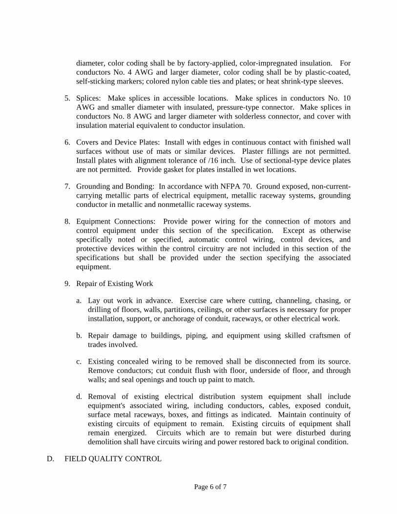
Page 6 of 7
diameter, color coding shall be by factory-applied, color-impregnated insulation. For conductors No. 4 AWG and larger diameter, color coding shall be by plastic-coated, self-sticking markers; colored nylon cable ties and plates; or heat shrink-type sleeves.
5. Splices: Make splices in accessible locations. Make splices in conductors No. 10 AWG and smaller diameter with insulated, pressure-type connector. Make splices in conductors No. 8 AWG and larger diameter with solderless connector, and cover with insulation material equivalent to conductor insulation.
6. Covers and Device Plates: Install with edges in continuous contact with finished wall surfaces without use of mats or similar devices. Plaster fillings are not permitted. Install plates with alignment tolerance of /16 inch. Use of sectional-type device plates are not permitted. Provide gasket for plates installed in wet locations.
7. Grounding and Bonding: In accordance with NFPA 70. Ground exposed, non-current-carrying metallic parts of electrical equipment, metallic raceway systems, grounding conductor in metallic and nonmetallic raceway systems.
8. Equipment Connections: Provide power wiring for the connection of motors and control equipment under this section of the specification. Except as otherwise specifically noted or specified, automatic control wiring, control devices, and protective devices within the control circuitry are not included in this section of the specifications but shall be provided under the section specifying the associated equipment.
9. Repair of Existing Work
a. Lay out work in advance. Exercise care where cutting, channeling, chasing, or drilling of floors, walls, partitions, ceilings, or other surfaces is necessary for proper installation, support, or anchorage of conduit, raceways, or other electrical work.
b. Repair damage to buildings, piping, and equipment using skilled craftsmen of trades involved.
c. Existing concealed wiring to be removed shall be disconnected from its source. Remove conductors; cut conduit flush with floor, underside of floor, and through walls; and seal openings and touch up paint to match.
d. Removal of existing electrical distribution system equipment shall include equipment's associated wiring, including conductors, cables, exposed conduit, surface metal raceways, boxes, and fittings as indicated. Maintain continuity of existing circuits of equipment to remain. Existing circuits of equipment shall remain energized. Circuits which are to remain but were disturbed during demolition shall have circuits wiring and power restored back to original condition.
D. FIELD QUALITY CONTROL
Page 7 of 7
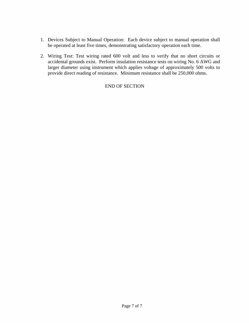
1. Devices Subject to Manual Operation: Each device subject to manual operation shall be operated at least five times, demonstrating satisfactory operation each time.
2. Wiring Test: Test wiring rated 600 volt and less to verify that no short circuits or accidental grounds exist. Perform insulation resistance tests on wiring No. 6 AWG and larger diameter using instrument which applies voltage of approximately 500 volts to provide direct reading of resistance. Minimum resistance shall be 250,000 ohms.
END OF SECTION

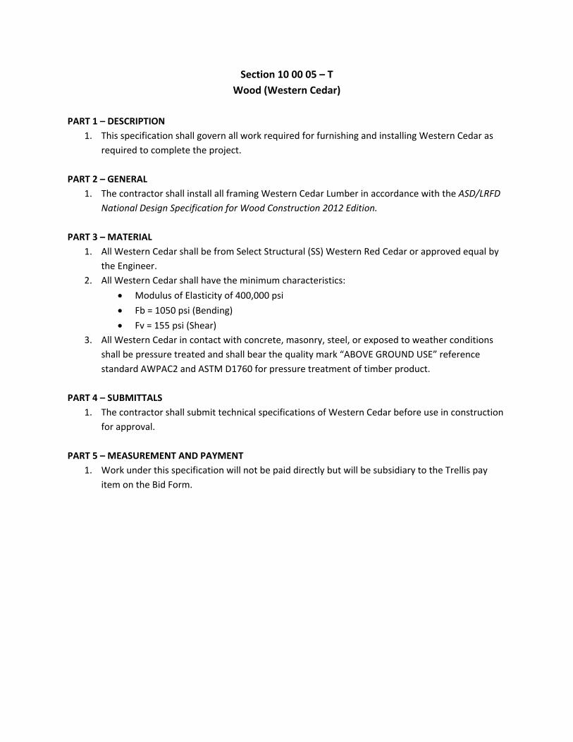
Section 10 00 05 – T
Wood (Western Cedar)
PART 1 – DESCRIPTION
1. This specification shall govern all work required for furnishing and installing Western Cedar as
required to complete the project.
PART 2 – GENERAL
1. The contractor shall install all framing Western Cedar Lumber in accordance with the ASD/LRFD
National Design Specification for Wood Construction 2012 Edition.
PART 3 – MATERIAL
1. All Western Cedar shall be from Select Structural (SS) Western Red Cedar or approved equal by
the Engineer.
2. All Western Cedar shall have the minimum characteristics:
Modulus of Elasticity of 400,000 psi
Fb = 1050 psi (Bending)
Fv = 155 psi (Shear)
3. All Western Cedar in contact with concrete, masonry, steel, or exposed to weather conditions
shall be pressure treated and shall bear the quality mark “ABOVE GROUND USE” reference
standard AWPAC2 and ASTM D1760 for pressure treatment of timber product.
PART 4 – SUBMITTALS
1. The contractor shall submit technical specifications of Western Cedar before use in construction
for approval.
PART 5 – MEASUREMENT AND PAYMENT
1. Work under this specification will not be paid directly but will be subsidiary to the Trellis pay
item on the Bid Form.


![R&D Proposal on CCPD with HV/HR-CMOS - CERN Documents...R&D Proposal on CCPD with HV/HR-CMOS INFN Group V ... Following an idea proposed by I. Peric in 2007 [01], we want to investigate](https://img.pdfslide.us/doc/110x75/5ae009ca7f8b9a97518cc238/rd-proposal-on-ccpd-with-hvhr-cmos-cern-documentsrd-proposal-on-ccpd-with.jpg)