Embed Size (px)
Citation preview

SECTION 030020 PORTLAND CEMENT CONCRETE
1. DESCRIPTION This specification shall govern for the materials used; for the storing and handling of materials; and for the proportioning and mixing of concrete for culverts, manholes, inlets, curb and gutter, sidewalks, driveways, curb ramps, headwalls and wingwalls, riprap, and incidental concrete construction. The concrete shall be composed of Portland cement, aggregates (fine and coarse), admixtures if desired or required, and water, proportioned and mixed as hereinafter provided. 2. MATERIALS (1) Cement The cement shall be either Type I, II or III Portland cement conforming to ASTM Designation: C150, modified as follows: Unless otherwise specified by the Engineer, the specific surface area of Type I and II
cements shall not exceed 2000 square centimeters per gram (Wagner Turbidimeter – TxDOT Test Method Tex-310-D). For concrete piling, the above limit on specific surface area is waived for Type II cement only. The Contractor shall furnish the Engineer, with each shipment, a statement as to the specific surface area of the cement expressed in square centimeters per gram.
For cement strength requirements, either the flexural or compressive test may be used. Either Type I or II cement shall be used unless Type II is specified on the plans. Except when Type II is specified on the plans, Type III cement may be used when the anticipated air temperature for the succeeding 12 hours will not exceed 60°F. Type III cement may be used in all precast prestressed concrete, except in piling when Type II cement is required for substructure concrete. Different types of cement may be used in the same structure, but all cement used in any one monolithic placement shall be of the same type and brand. Only one brand of each type will be permitted in any one structure unless otherwise authorized by the Engineer. Cement may be delivered in bulk where adequate bin storage is provided. All other cement shall be delivered in bags marked plainly with the name of the manufacturer and the type of cement. Similar information shall be provided in the bills of lading accompanying each shipment of packaged or bulk cement. Bags shall contain 94 pounds net. All bags shall be in good condition at time of delivery. All cement shall be properly protected against dampness. No caked cement will be accepted. Cement remaining in storage for a prolonged period of time may be retested and rejected if it fails to conform to any of the requirements of these specifications.
030020 Page 1 of 13
Rev. 10-30-2014

(2) Mixing Water Water for use in concrete and for curing shall be free from oils, acids, organic matter or other deleterious substances and shall not contain more than 1000 parts per million of chlorides as CL nor more than 1000 parts per million of sulfates as SO4.
Water from municipal supplies approved by the State Health Department will not require testing, but water from other sources will be sampled and tested before use in structural concrete. Tests shall be made in accordance with the "Method of Test for Quality of Water to be Used in Concrete" (AASHTO Method T26), except where such methods are in conflict with provisions of this specification. (3) Coarse Aggregate Coarse aggregate shall consist of durable particles of gravel, crushed blast furnace slag, crushed stone, or combinations thereof; free from frozen material or injurious amount of salt, alkali, vegetable matter, or other objectionable material either free or as an adherent coating; and its quality shall be reasonably uniform throughout. It shall not contain more than 0.25 percent by weight of clay lumps, nor more than 1.0 percent by weight of shale, nor more than 5 percent by weight of laminated and/or friable particles when tested in accordance with TxDOT Test Method Tex-413-A. It shall have a wear of not more than 40 percent when tested in accordance with TxDOT Test Method Tex-410-A. Unless otherwise specified on the plans, coarse aggregate will be subjected to five cycles of the soundness test in accordance with TxDOT Test Method Tex-411-A. The loss shall not be greater than 12 percent when sodium sulfate is used, or 18 percent when magnesium sulfate is used. Permissible sizes of aggregate shall be governed by Table 4 and Table 1, except that when exposed aggregate surfaces are required, coarse aggregate gradation will be as specified on the plans. When tested by approved methods, the coarse aggregate, including combinations of aggregates when used, shall conform to the grading requirements shown in Table 1.
030020 Page 2 of 13
Rev. 10-30-2014

TABLE 1 Coarse Aggregate Gradation Chart
Percent Retained on Each Sieve
Aggregate Grade No.
Nominal Size
2-½ In.
2 In.
1-½ In.
1 In.
3/4 In.
1/2 In.
3/8 In.
No. 4
No. 8
1 2 in. 0 0 to 20
15 to 50
60 to 80
95 to 100
2 (467)* 1-½ in. 0 0 to 5
30 to 65
70 to 90
95 to 100
4 (57)* 1 in. 0 0 to 5
40 to 75
90 to 100
95 to 100
8 3/8 in. 0 0 to 5
35 to 80
90 to 100
*Numbers in parenthesis indicate conformance with ASTM C33. The aggregate shall be washed. The Loss by Decantation (TxDOT Test Method Tex-406-A) plus the allowable weight of clay lumps, shall not exceed one percent, or the value shown on the plans, whichever is smaller. (4) Fine Aggregate Fine aggregate shall consist of clean, hard, durable and uncoated particles of natural or manufactured sand or a combination thereof, with or without a mineral filler. It shall be free from frozen material or injurious amounts of salt, alkali, vegetable matter or other objectionable material and it shall not contain more than 0.5 percent by weight of clay lumps. When subjected to the color test for organic impurities (TxDOT Test Method Tex-408-A), it shall not show a color darker than standard. The fine aggregate shall produce a mortar having a tensile strength equal to or greater than that of Ottawa sand mortar when tested in accordance with TxDOT Test Method Tex-317-D. Where manufactured sand is used in lieu of natural sand for slab concrete subject to direct traffic, the acid insoluble residue of the fine aggregate shall be not less than 28 percent by weight when tested in accordance with TxDOT Test Method Tex-612-J. When tested by approved methods, the fine aggregate or combination of aggregates, including mineral filler, shall conform to the grading requirements shown in Table 2.
030020 Page 3 of 13
Rev. 10-30-2014

TABLE 2 Fine Aggregate Gradation Chart
Percent Retained on Each Sieve
Aggregate Grade No. 3/8 In. No. 4 No. 8 No. 16 No. 30 No. 50 No. 100 No. 200
1 0 0 to 5 0 to 20 15 to 50 35 to 75 70 to 90 90 to 100 97 to 100
NOTE 1: Where manufactured sand is used in lieu of natural sand, the percent retained on the
No. 200 sieve shall be 94 to 100. NOTE 2: Where the sand equivalent value is greater than 85, the retainage on the No. 50 sieve
may be 70 to 94 percent. Fine aggregate will be subjected to the Sand Equivalent Test (TxDOT Test Method Tex-203-F). The sand equivalent shall not be less than 80 nor less than the value shown on the plans, whichever is greater. For concrete Classes ‘A’ and ‘C’, the fineness modulus as defined below for fine aggregates shall be between 2.30 and 3.10. The fineness modulus will be determined by adding the percentages by weight retained on the following sieves, and dividing by 100; Nos. 4, 8, 16, 30, 50 and 100. (5) Mineral Filler Mineral filler shall consist of stone dust, clean crushed sand, or other approved inert material. (6) Mortar (Grout) Mortar for repair of concrete shall consist of 1 part cement, 2 parts finely graded sand, and enough water to make the mixture plastic. When required to prevent color difference, white cement shall be added to produce the color required. When required by the Engineer, latex adhesive shall be added to the mortar. (7) Admixtures Calcium Chloride will not be permitted. Unless otherwise noted, air-entraining, retarding and water-reducing admixtures may be used in all concrete and shall conform to the following requirements: A "water-reducing, retarding admixture" is defined as a material which, when added to a concrete mixture in the correct quantity, will reduce the quantity of mixing water required to produce concrete of a given consistency and will retard the initial set of the concrete. A "water-reducing admixture" is defined as a material which, when added to a concrete mixture in the correct quantity, will reduce the quantity of mixing water required to produce concrete of a
030020 Page 4 of 13
Rev. 10-30-2014

given consistency. (a) Retarding and Water-Reducing Admixtures. The admixture shall meet the
requirements for Type A and Type D admixture as specified in ASTM Designation: C494, modified as follows:
(1) The water-reducing retarder shall retard the initial set of the concrete
a minimum of 2 hours and a maximum of 4 hours, at a specified dosage rate, at a temperature of 90°F.
(2) The cement used in any series of tests shall be either the cement
proposed for specific work or a "reference" Type I cement from one mill.
(3) Unless otherwise noted on the plans, the minimum relative durability
factor shall be 80. The air-entraining admixture used in the referenced and test concrete shall be neutralized Vinsol resin. (b) Air-Entraining Admixture. The admixture shall meet the requirements of
ASTM Designation: C260, modified as follows: (1) The cement used in any series of tests shall be either the cement
proposed for specific work or a "reference" Type I cement from one mill.
(2) Unless otherwise noted on the plans, the minimum relative durability
factor shall be 80. The air-entraining admixture used in the referenced concrete shall be neutralized Vinsol resin. 3. STORAGE OF CEMENT All cement shall be stored in well-ventilated weatherproof buildings or approved bins, which will protect it from dampness or absorption of moisture. Storage facilities shall be ample, and each shipment of packaged cement shall be kept separated to provide easy access for identification and inspection. The Engineer may permit small quantities of sacked cement to be stored in the open for a maximum of 48 hours on a raised platform and under waterproof covering. 4. STORAGE OF AGGREGATE The method of handling and storing concrete aggregate shall prevent contamination with foreign materials. If the aggregates are stored on the ground, the sites for the stockpiles shall be clear of all vegetation and level. The bottom layer of aggregate shall not be disturbed or used without recleaning.
030020 Page 5 of 13
Rev. 10-30-2014

When conditions require the use of two or more sizes of aggregates, they shall be separated to prevent intermixing. Where space is limited, stockpiles shall be separated by physical barriers. Methods of handling aggregates during stockpiling and subsequent use shall be such that segregation will be minimized. Unless otherwise authorized by the Engineer, all aggregate shall be stockpiled at least 24 hours to reduce the free moisture content. 5. MEASUREMENT OF MATERIALS The measurement of the materials, except water, used in batches of concrete, shall be by weight. The fine aggregate, coarse aggregate and mineral filler shall be weighed separately. Where bulk cement is used, it shall be weighed separately, but batch weighing of sacked cement will not be required. Where sacked cement is used, the quantities of material per batch shall be based upon using full bags of cement. Batches involving the use of fractional bags will not be permitted. Allowance shall be made for the water content in the aggregates. Bags of cement varying more than 3 percent from the specified weight of 94 pounds may be rejected, and when the average weight per bag in any shipment, as determined by weighing 50 bags taken at random, is less than the net weight specified, the entire shipment may be rejected. If the shipment is accepted, the Engineer will adjust the concrete mix to a net weight per bag fixed by an average of all individual weights which are less than the average weight determined from the total number weighed. 6. CLASSIFICATION AND MIX DESIGN It shall be the responsibility of the Contractor to furnish the mix design, using a coarse aggregate factor acceptable to the Engineer, for the class(es) of concrete specified. The mix shall be designed by a qualified concrete technician to conform with the requirements contained herein and in accordance with the THD Bulletin C-11. The Contractor shall perform, at his own expense, the work required to substantiate the design, except the testing of strength specimens, which will be done by the Engineer. Complete concrete design data shall be submitted to the Engineer for approval. It shall also be the responsibility of the Contractor to determine and measure the batch quantity of each ingredient, including all water, so that the mix conforms to these specifications and any other requirements shown on the plans. Trial batches will be made and tested using all of the proposed ingredients prior to placing the concrete, and when the aggregate and/or brand of cement or admixture is changed. Trial batches shall be made in the mixer to be used on the job. When transit mix concrete is to be used, the trial designs will be made in a transit mixer representative of the mixers to be used. Batch size shall not be less than 50 percent of the rated mixing capacity of the truck. Mix designs from previous or concurrent jobs may be used without trial batches if it is shown that
030020 Page 6 of 13
Rev. 10-30-2014

no substantial change in any of the proposed ingredients has been made. The coarse aggregate factor shall not be more than 0.82, except that when the voids in the coarse aggregate exceed 48 percent of the total dry loose volume, the coarse aggregate factor shall not exceed 0.85. The coarse aggregate factor shall not be less than 0.70 for Grades 1, 2 and 3 aggregates. If the strength required for the class of concrete being produced is not secured with the cement specified in Table 4, the Contractor may use an approved water-reducing or retarding admixture, or he shall furnish aggregates with different characteristics which will produce the required results. Additional cement may be required or permitted as a temporary measure until the redesign is checked. Water-reducing or retarding agents may be used with all classes of concrete at the option of the Contractor. When water-reducing or retarding agents are used at the option of the Contractor, reduced dosage of the admixture will be permitted. Entrained air will be required in accordance with Table 4. The concrete shall be designed to entrain 5 percent air when Grade 2 coarse aggregate is used and 6 percent when Grade 3 coarse aggregate is used. Concrete as placed in the structure shall contain the proper amount as required above with a tolerance of plus or minus 1.5 percentage points. Occasional variations beyond this tolerance will not be cause for rejection. When the quantity of entrained air is found to be above 7 percent with Grade 2 coarse aggregate or above 8 percent for Grade 3 coarse aggregate, additional test beams or cylinders will be made. If these beams or cylinders pass the minimum flexural or compressive requirements, the concrete will not be rejected because of the variation in air content. 7. CONSISTENCY In cases where the consistency requirements cannot be satisfied without exceeding the maximum allowable amount of water, the Contractor may use, or the Engineer may require, an approved water-reducing or retarding agent, or the Contractor shall furnish additional aggregates or aggregates with different characteristics, which will produce the required results. Additional cement may be required or permitted as a temporary measure until aggregates are changed and designs checked with the different aggregates or admixture. The consistency of the concrete as placed should allow the completion of all finishing operations without the addition of water to the surface. When field conditions are such that additional moisture is needed for the final concrete surface finishing operation, the required water shall be applied to the surface by fog spray only, and shall be held to a minimum. The concrete shall be workable, cohesive, possess satisfactory finishing qualities, and of the stiffest consistency that can be placed and vibrated into a homogenous mass. Excessive bleeding shall be avoided. Slump requirements will be as specified in Table 3.
030020 Page 7 of 13
Rev. 10-30-2014

TABLE 3 Slump Requirements
Concrete Designation Desired Slump Max. Slump Structural Concrete:
(1) Thin-Walled Sections (9" or less) (2) Slabs, Caps, Columns, Piers, Wall Sections over 9", etc.
Underwater or Seal Concrete Riprap, Curb, Gutter and Other Miscellaneous Concrete
4 inches 3 inches 5 inches 2.5 inches
5 inches 4 inches 6 inches 4 inches
NOTE: No concrete will be permitted with slump in excess of the maximums shown.
8. QUALITY OF CONCRETE General The concrete shall be uniform and workable. The cement content, maximum allowable water-cement ratio, the desired and maximum slump and the strength requirements of the various classes of concrete shall conform to the requirements of Table 3 and Table 4 and as required herein. During the process of the work, the Engineer or his designated representative will cast test cylinders or beams as a check on the compressive or flexural strength of the concrete actually placed. Test cylinders must be picked up by the testing lab within 24 hours. A test shall be defined as the average of the breaking strength of two cylinders or two beams, as the case may be. Specimens will be tested in accordance with TxDOT Test Methods Tex-418-A or Tex-420-A. Test beams or cylinders will be required as specified in the contract documents. For small placements on structures such as manholes, inlets, culverts, wingwalls, etc., the Engineer may vary the number of tests to a minimum of one for each 25 cubic yards placed over a several day period. All test specimens, beams or cylinders, representing tests for removal of forms and/or falsework shall be cured using the same methods, and under the same conditions as the concrete represented. "Design Strength" beams and cylinders shall be cured in accordance with THD Bulletin C-11. The Contractor shall provide and maintain curing facilities as described in THD Bulletin C-11 for the purpose of curing test specimens. Provision shall be made to maintain the water in the curing tank at temperatures between 70°F and 90°F. When control of concrete quality is by twenty-eight-day compressive tests, job control will be by seven-day compressive tests which are shown to provide the required twenty-eight-day strength, based on results from trial batches. If the required seven-day strength is not secured with the
030020 Page 8 of 13
Rev. 10-30-2014

cement specified in Table 4, changes in the batch design will be made. TABLE 4 Classes of Concrete
Class of Concrete
Sacks Cement per C.Y. (min.)
Minimum Compressive Strength (f'c) 28-Day(psi)
Min. Beam Strength 7-Day (psi)
Maximum Water-Cement Ratio (gal/sack)
Coarse Aggregate No.
A* 5.0 3000 500*** 6.5 2-4-8****
B* 4.5 2500 417 8.0 2-4-8****
C* 6.0 3600 600*** 6.0 1-2-4**
D 6.0 3000 500 7.0 2-4
S 6.5 4000 570 5.0 2-4
*Entrained Air (slabs, piers and bent concrete).
**Grade 1 Coarse Aggregate may be used in foundation only (except cased drilled shafts).
***When Type II Cement is used with Class C Concrete, the 7-day beam break requirement will be 550 psi; with Class A Concrete, the minimum 7-day beam break requirement will be 460 psi.
****Permission to use Grade 8 Aggregate must have prior approval of the Engineer. 9. MIXING CONDITIONS The concrete shall be mixed in quantities required for immediate use. Any concrete which is not in place within the limits outlined in City Standard Specification Section 038000 "Concrete Structures", Article "Placing Concrete-General", shall not be used. Retamping of concrete will not be permitted. In threatening weather, which may result in conditions that will adversely affect the quality of the concrete to be placed, the Engineer may order postponement of the work. Where work has been started and changes in weather conditions require protective measures, the Contractor shall furnish adequate shelter to protect the concrete against damage from rainfall, or from freezing temperatures. If necessary to continue operations during rainfall, the Contractor shall also provide protective coverings for the material stockpiles. Aggregate stockpiles need be covered only to the extent necessary to control the moisture conditions in the aggregates to adequately control the consistency of the concrete. 10. MIXING AND MIXING EQUIPMENT All equipment, tools, and machinery used for hauling materials and performing any part of the work shall be maintained in such condition to insure completion of the work underway without excessive delays for repairs or replacements. The mixing shall be done in a batch mixer of approved type and size that will produce uniform
030020 Page 9 of 13
Rev. 10-30-2014

distribution of the material throughout the mass. Mixers may be either the revolving drum type or the revolving blade type, and shall be capable of producing concrete meeting the requirements of these specifications. After all the ingredients are assembled in the drum, the mixing shall continue not less than 1 minute for mixers of one cubic yard or less capacity plus 15 seconds for each additional cubic yard or portion thereof. The mixer shall operate at the speed and capacity designated by the Mixer Manufacturers Bureau of the Associated General Contractors of America. The mixer shall have a plate affixed showing the manufacturer's recommended operating data. The absolute volume of the concrete batch shall not exceed the rated capacity of the mixer. The entire contents of the drum shall be discharged before any materials are placed therein for the succeeding batch. The first batch of concrete materials placed in the mixer for each placement shall contain an extra quantity of sand, cement and water sufficient to coat the inside surface of the drum. Upon the cessation of mixing for any considerable length of time, the mixer shall be thoroughly cleaned. The concrete mixer shall be equipped with an automatic timing device which is put into operation when the skip is raised to its full height and dumping. This device shall lock the discharging mechanism and prevent emptying of the mixer until all the materials have been mixed together for the minimum time required, and it shall ring a bell after the specified time of mixing has elapsed. The water tank shall be arranged so that the amount of water can be measured accurately, and when the tank starts to discharge, the inlet supply shall cut off automatically. Whenever a concrete mixer is not adequate or suitable for the work, it shall be removed from the site upon a written order from the Engineer and a suitable mixer provided by the Contractor. Pick-up and thro-over blades in the drum of the mixer which are worn down more than 10 percent in depth shall be repaired or replaced with new blades. Improperly mixed concrete shall not be placed in the structure. Job mix concrete shall be concrete mixed in an approved batch mixer in accordance with the requirements stated above, adjacent to the structure for which the concrete is being mixed, and moved to the placement site in non-agitating equipment. 11. READY-MIX PLANTS A. General. It shall be the Contractor's responsibility to furnish concrete meeting all
requirement of the governing specification sections, and concrete not meeting the slump, workability and consistency requirements of the governing specification sections shall not
030020 Page 10 of 13
Rev. 10-30-2014

be placed in the structure or pavement. Ready-Mixed Concrete shall be mixed and delivered by means of one of the following
approved methods. (1) Mixed completely in a stationary mixer and transported to the point of
delivery in a truck agitator or a truck mixer operating at truck agitator or truck mixer agitation speed. (Central-Mix Concrete)
(2) Mixed complete in a truck mixer and transported to the placement site at
mixing and/or agitating speed (Transit-Mix Concrete), subject to the following provisions:
(a) Truck mixers will be permitted to transport concrete to the job site at
mixing speed if equipped with double actuated counters which will separate revolutions at mixing speed from total revolutions.
(b) Truck mixers equipped with a single actuated counter counting total
revolutions of the drum shall mix the concrete at the plant not less than 50 nor more than 70 revolutions at mixing speed, transport it to the job site at agitating speed and complete the required mixing before placing the concrete.
(3) Mixed completely in a stationery mixer and transported to the job site in
approved non-agitating trucks with special bodies. This method of transporting will be permitted for concrete pavement only.
B. Equipment. (1) Batching Plant. The batching plant shall be provided with adequate bins for
batching all aggregates and materials required by the specifications. Bulk cement shall be weighed on a scale separate from those used for other
materials and in a hopper entirely free and independent of that used for weighing the aggregates.
(2) Mixers and Agitators. (a) General: Mixers shall be of an approved stationary or truck-type capable of
combining the ingredients into a thoroughly mixed and uniform mass. Facilities shall be provided to permit ready access to the inside of the drum
for inspection, cleaning and repair of blades. Mixers and agitators shall be subject to daily examination for changes in
condition due to accumulation of hardened concrete and/or wear of blades, and any hardened concrete shall be removed before the mixer will be permitted to be used. Worn blades shall be repaired or replaced with new in
030020 Page 11 of 13
Rev. 10-30-2014

accordance with the manufacturer's design and arrangement for that particular unit when any part or section is worn as much as 10 percent below the original height of the manufacturer's design.
(b) Stationary Mixers: These shall conform to the requirements of Article
"Mixing and Mixing Equipment". Truck mixers mounted on a stationary base will not be considered as a stationary mixer.
(c) Truck Mixers: In addition, truck mixers shall comply with the following
requirements: An engine in satisfactory working condition and capable of accurately
gauging the desired speed of rotation shall be mounted as an integral part of the mixing unit for the purpose of rotating the drum. Truck mixers equipped with a transmission that will govern the speed of the drum within the specified revolutions per minute (rpm) will not require a separate engine.
All truck mixers shall be equipped with actuated counters by which the
proper number of revolutions of the drum, as specified in Article 11. A. above, may be readily verified. The counters shall be read and recorded at the start of mixing at mixing speeds.
Each until shall have adequate water supply and accurate metering or
gauging devices for measuring the amount used. (d) Agitators: Concrete agitators shall be of the truck type, capable of
maintaining a thoroughly mixed and uniform concrete mass and discharging it within the same degree of uniformity specified for mixers. Agitators shall comply with all of the requirements for truck mixers, except for the actual mixing requirements.
C. Operation of Plant and Equipment. Delivery of ready-mixed concrete shall equal or exceed the rate approved by the Engineer for continuous placement. In all cases, the delivery of concrete to the placement site shall assure compliance with the time limits in the applicable specification for depositing successive batches in any monolithic unit. The Contractor shall satisfy the Engineer that adequate standby trucks are available. A standard ticket system will be used for recording concrete batching, mixing and delivery date. Tickets will be delivered to the job inspector. Loads arriving without ticket and/or in unsatisfactory condition shall not be used. When a stationary mixer is used for the entire mixing operation, the mixing time for one cubic yard of concrete shall be one minute plus 15 seconds for each additional cubic yard or portion thereof. This mixing time shall start when all cement, aggregates and initial water have entered the drum.
030020 Page 12 of 13
Rev. 10-30-2014

The mixer shall be charged so that some of the mixing water will enter the drum in advance of the cement and aggregate. All of the mixing water shall be in the drum by the end of the first one-fourth of the specified mixing time. Water used to flush down the blades after charging shall be accurately measured and included in the quantity of mixing water. The introduction of the initial mixing water, except blade wash down water and that permitted in this Article, shall be prior to or simultaneous with the charging of the aggregates and cement. The loading of truck mixers shall not exceed 63 percent of the total volume of the drum. When used as an agitator only, the loading shall not exceed 80 percent of the drum volume. When Ready-Mix Concrete is used, additional mortar (one sack cement, three parts sand and sufficient water) shall be added to the batch to coat the drum of the mixer or agitator truck, and this shall be required for every load of Class C concrete only and for the first batch from central mix plants. A portion of the mixing water, required by the batch design to produce the desired slump, may be withheld and added at the job site, but only with permission of the Engineer and under his supervision. When water is added under the above conditions, it shall be thoroughly mixed as specified below for water added at the job site. Mixing speed shall be attained as soon as all ingredients are in the mixer, and each complete batch (containing all the required ingredients) shall be mixed not less than 70 nor more than 100 revolutions of the drum at mixing speed except that when water is added at the job site, 25 revolutions (minimum) at mixing speed will be required to uniformly disperse the additional water throughout the mix. Mixing speed shall be as designated by the manufacturer. All revolutions after the prescribed mixing time shall be at agitating speed. The agitating speed shall be not less than one (1) nor more than five (5) rpm. The drum shall be kept in continuous motion from the time mixing is started until the discharge is completed. 12. PLACING, CURING AND FINISHING The placing of concrete, including construction of forms and falsework, curing and finishing, shall be in accordance with City Standard Specification Section 038000 "Concrete Structures". 13. MEASUREMENT AND PAYMENT Unless otherwise specified on the Bid Form, the quantities of concrete of the various classifications which will constitute the completed and accepted structure(s) in-place will be measured by the cubic yard, per each, square foot, square yard or linear foot, as the case may be. Measurement will be as shown on the drawings and/or in the Bid Form. Payment shall be full compensation for furnishing, hauling, mixing, placing, curing and finishing all concrete; all grouting and pointing; furnishing and placing drains; furnishing and placing metal flashing strips; furnishing and placing expansion joint material required by this specification or shown on the plans; and for all forms and falsework, labor, tools, equipment and incidentals necessary to complete the work.
030020 Page 13 of 13
Rev. 10-30-2014

SECTION 032020 REINFORCING STEEL
1. DESCRIPTION This specification shall govern the furnishing and placing of reinforcing steel, deformed and smooth, of the size and quantity designated on the plans and in accordance with these specifications. 2. MATERIALS Unless otherwise designated on the plans, all bar reinforcement shall be deformed, and shall conform to ASTM Designation: A 615, Grades 60 or 75, and shall be open hearth, basic oxygen, or electric furnace new billet steel. Large diameter new billet steel (Nos. 14 and 18), Grade 75, will be permitted for straight bars only. Where bending of bar sizes No. 14 or No. 18 of Grade 60 is required, bend testing shall be performed on representative specimens as described for smaller bars in the applicable ASTM Specification. The required bend shall be 90 degrees around a pin having a diameter of 10 times the nominal diameter of the bar. Spiral reinforcement shall be smooth (not deformed) bars or wire of the minimum diameter shown on the plans, and shall be made by one or more of the following processes: open hearth, basic oxygen, or electric furnace. Bars shall be rolled from billets reduced from ingots and shall comply with ASTM Designation: A 306, Grade 65 minimum (references to ASTM Designation: A 29 is voided). Dimensional tolerances shall be in accordance with ASTM Designation: A 615, or ASTM Designation: A 615, Grade 60, except for deformations. Wire shall be cold-drawn from rods that have been hot-rolled from billets and shall comply with ASTM Designation: A 185. In cases where the provisions of this specification are in conflict with the provisions of the ASTM Designation to which reference is made, the provisions of this specification shall govern. Report of chemical analysis showing the percentages of carbon, manganese, phosphorus and sulphur will be required for all reinforcing steel when it is to be welded.
032020 Page 1 of 6
Rev. 10-30-2014

The nominal size and area and the theoretical weight of reinforcing steel bars covered by this specification are as follows:
Bar Size Number
Nominal Diameter, In.
Nominal Area, Sq. In.
Weight per Linear Foot,
Pounds
2 0.250 0.05 0.167
3 0.375 0.11 0.376
4 0.500 0.20 0.668
5 0.625 0.31 1.043
6 0.750 0.44 1.502
7 0.875 0.60 2.044
8 1.000 0.79 2.670
9 1.128 1.00 3.400
10 1.270 1.27 4.303
11 1.410 1.56 5.313
14 1.693 2.25 7.6
18 2.257 4.00 13.60 Smooth round bars shall be designated by size number through No. 4. Smooth bars larger than No. 4 shall be designated by diameter in inches. When wire is ordered by gauge numbers, the following relation between gauge number and diameter, in inches, shall apply unless otherwise specified:
Gauge Number
Equivalent Diameter, Inches
Gauge Number
Equivalent Diameter, Inches
0 0.3065 8 0.1620
1 0.2830 9 0.1483
2 0.2625 10 0.1350
3 0.2437 11 0.1205
4 0.2253 12 0.1055
5 0.2070 13 0.0915
6 0.1920 14 0.0800
7 0.1770
032020 Page 2 of 6
Rev. 10-30-2014

3. BENDING The reinforcement shall be bent cold, true to the shapes indicated on the plans. Bending shall preferably be done in the shop. Irregularities in bending shall be cause for rejection. Unless otherwise shown on the plans, the inside diameter of bar bends, in terms of the nominal bar diameter (d), shall be as follows: Bends of 90 degrees and greater in stirrups, ties and other secondary bars that enclose
another bar in the bend:
Grade 60
#3, #4, #5 4d
#6, #7, #8 5d
All bends in main bars and in secondary bars not covered above:
Grade 60 Grade 75
#3 thru #8 6d --
#9, #10 8d --
#11 8d 8d
#14, #18 10d --
032020 Page 3 of 6
Rev. 10-30-2014

4. TOLERANCES Fabricating tolerances for bars shall be within 3 percent of specified or as follows:
5. STORING Steel reinforcement shall be stored above the surface of the ground upon platforms, skids or other supports, and shall be protected as far as practicable from mechanical injury and surface deterioration caused by exposure to conditions producing rust. When placed in the work, reinforcement shall be free from dirt, paint, grease, oil, or other foreign materials. Reinforcement shall be free from injurious defects such as cracks and laminations. Rust, surface seams, surface irregularities or mill scale will not be cause for rejection, provided the minimum dimensions, cross-sectional area and tensile properties of a hand wire crushed specimen meets the physical requirements for size and grade of steel specified. 6. SPLICES No splicing of bars, except when provided on the plans or specified herein, will be permitted without written approval of the Engineer. Splices will not be permitted in main reinforcement at points of maximum stress. When permitted in main bars, splices in adjacent bars shall be staggered a minimum of two splice lengths.
032020 Page 4 of 6
Rev. 10-30-2014

TABLE 1 Minimum Lap Requirements Lap Uncoated Coated Lap in inches > 40d 60d Where: d = bar diameter in inches Welding of reinforcing bars may be used only where shown on the plans or as permitted herein. All welding operations, processes, equipment, materials, workmanship and inspection shall conform to the requirements of the drawings and industry standards. All splices shall be of such dimension and character as to develop the full strength of bar being spliced. End preparation for butt welding reinforcing bars shall be done in the field. Delivered bars shall be of sufficient length to permit this practice. For box culvert extensions with less than one foot of fill, the existing longitudinal bars shall have a 20-diameter lap with the new bars. For box culvert extensions with more than one foot of fill, a minimum of 6 inches lap will be required. Unless otherwise shown on the plans, dowel bars transferring tensile stresses shall have a minimum embedment equal to the minimum lap requirements shown in Table 1. Shear transfer dowels shall have a minimum embedment of 12 inches. 7. PLACING Reinforcement shall be placed as near as possible in the position shown on the plans. Unless otherwise shown on the plans, dimensions shown for reinforcement are to the centers of the bars. In the plane of the steel parallel to the nearest surface of concrete, bars shall not vary from plan placement by more than one-twelfth of the spacing between bars. In the plane of the steel perpendicular to the nearest surface of concrete, bars shall not vary from plan placement by more than one-quarter inch. Cover of concrete to the nearest surface of steel shall meet the above requirements but shall never be less than one inch or as otherwise shown on the plans. Vertical stirrups shall always pass around the main tension members and be attached securely thereto. The reinforcing steel shall be spaced its required distance from the form surface by means of approved galvanized metal spacers, metal spacers with plastic coated tips, stainless steel spacers, plastic spacers, or approved pre-cast mortar or concrete blocks. For approval of plastic spacers on the project, representative samples of the plastic shall show no visible indications of deterioration after immersion in a 5 percent solution of sodium hydroxide for 120 hours. All reinforcing steel shall be tied at all intersections, except that where spacing is less than one foot in each direction, alternate intersections only need be tied. Before any concrete is placed, all mortar shall be cleaned from the reinforcement. Precast mortar or concrete blocks to be used for holding steel in position adjacent to formed surfaces shall be cast in molds meeting the approval of the Engineer and shall be cured by covering with wet burlap or
032020 Page 5 of 6
Rev. 10-30-2014

cotton mats for a period of 72 hours. The blocks shall be cast in the form of a frustum of a cone or pyramid with the smaller face placed against the forms. A suitable tie wire shall be provided in each block, to be used for anchoring to the steel. Except in unusual cases, and when specifically otherwise authorized by the Engineer, the size of the surface to be placed adjacent to the forms shall not exceed two and one-half inches square or the equivalent thereof in cases where circular or rectangular areas are provided. Blocks shall be cast accurately to the thickness required, and the surface to be placed adjacent to the forms shall be a true plane free of surface imperfections. Reinforcement shall be supported and tied in such manner that a sufficiently rigid case of steel is provided. If the cage is not adequately supported to resist settlement or floating upward of the steel, overturning of truss bars or movement in any direction during concrete placement, permission to continue concrete placement will be withheld until corrective measures are taken. Sufficient measurements shall be made during concrete placement to insure compliance with the first paragraph of Article 7 of this specification. Mats of wire fabric shall overlap each other sufficiently to maintain a uniform strength and shall be fastened securely at the ends and edges. No concrete shall be deposited until the Engineer has inspected the placement of the reinforcing steel and given permission to proceed. 8. MEASUREMENT AND PAYMENT Unless otherwise specified on the Bid Form, reinforcing steel is considered subsidiary to the various items shown in the Bid Form and shall not be measured and paid for as a separate item.
032020 Page 6 of 6
Rev. 10-30-2014

SECTION 038000
CONCRETE STRUCTURES 1. DESCRIPTION This specification shall govern for construction of all types of structures involving the use of structural concrete, except where the requirements are waived or revised by other governing specifications. All concrete structures shall be constructed in accordance with the design requirements and details shown on the plans; in conformity with the pertinent provisions of the items contracted for; the incidental specifications referred to; and in conformity with the requirements herein. 2. MATERIALS (1) Concrete. All concrete shall conform to the provisions of City Standard Specification Section 030020 "Portland Cement Concrete". The class of concrete for each type of structure or unit shall be as specified on the plans or by pertinent governing specifications. (2) Expansion Joint Material.
(a) Preformed Fiber Material. Preformed fiber expansion joint material shall be of the dimensions shown on the plans. The material shall be one of the following types, unless otherwise noted on the plans:
1. Preformed Bituminous Fiber Materials shall meet the requirements of ASTM
Designation: D1751 "Standard Specification for Preformed Expansion Joint Filler for Concrete Paving and Structural Construction (Non-extruding and Resilient Bituminous Types)".
2. Preformed Non-Bituminous Fiber Material shall meet the requirements of ASTM
Designation: D1751 "Standard Specification for Preformed Expansion Joint Filler for Concrete Paving and Structural Construction (Non-extruding and Resilient Bituminous Types)", except that the requirements pertaining to bitumen content, density and water absorption shall be voided.
3. Redwood.
(b) Joint Sealing Materials. Unless otherwise shown on the drawings, joint sealing
material shall conform to the following requirements. The material shall adhere to the sides of the concrete joint or crack and shall form an effective seal against infiltration of water and incompressibles. The material shall not crack or break when exposed to low temperatures.
038000
Page 1 of 19 Rev. 3-25-2015

1. Class 1-a. (Two-Component, Synthetic Polymer, Cold-Extruded Type). Curing is to be by polymerization and not by evaporation of solvent or fluxing of harder particles. This type is specifically designed for vertical or sloping joints and hence not self-leveling. It shall cure sufficiently at an average temperature of 77 degrees F ± 3 degrees F in a maximum of 24 hours. For performance requirements see under 2.(2)(b)2. below.
2. Class 1-b. (Two-Component, Synthetic Polymer, Cold-Pourable, Self-Leveling
Type). Curing is to be by polymerization and not by evaporation of solvent or fluxing of harder particles. It shall cure sufficiently at an average temperature of 77 degrees F ± 3 degrees F in a maximum of 3 hours.
Performance Requirements: Class 1-a and Class 1-b joint materials, when tested in accordance with TxDOT Test Method Tex-525-C, shall meet the above curing times and the following requirements:
It shall be of such consistency that it can be mixed and poured, or mixed and extruded into joints at temperatures above 60 degrees F.
Penetration, 77º F.:
150 gm. cone, 5 sec., max., cm.................. 0.90 Bond and Extension 75%, Oº F, 5 cycles:
Dry Concrete Blocks............................ Pass Wet Concrete Blocks............................ Pass Steel Blocks...(Primed if specified by manuf.). Pass Flow at 200º F................................. None Water Content % by weight, max................. 5.0
Resilience: Original sample min. % (cured)................. 50 Oven aged at 158º F min. % .................... 50
For Class 1-a Material Only: Cold Flow (10 min.)............................ None
(c) Asphalt Board. Asphalt Board shall consist of two liners of 0.016-inch asphalt impregnated paper, filled with a mastic mixture of asphalt and vegetable fiber and/or mineral filler. Boards shall be smooth, flat and sufficiently rigid to permit installation. When tested in accordance with TxDOT Test Method Tex-524-C, the asphalt board shall not deflect from the horizontal more than one inch in three and one-half inches (1" in 3½").
(d) Rebonded Neoprene Filler. Rebonded neoprene filler shall consist of ground closed-cell neoprene particles, rebonded and molded into sheets of uniform thickness, of the dimensions shown on plans.
Filler material shall have the following physical properties and shall meet the requirements of ASTM Designation: D1752 “Standard Specification for Preformed Sponge Rubber and Cork Expansion Joint Fillers for Concrete Paving and Structural Construction”, Type 1, where applicable:
038000
Page 2 of 19 Rev. 3-25-2015

PROPERTY
METHOD
REQUIREMENT
Color
ASTM D1752, Type 1
Black
Density
ASTM D1752, Type 1
40 lb./ft3 Min.
Recovery
ASTM D1752, Type 1
90% Min.
Compression
ASTM D1752, Type 1
50 to 500 psi
Extrusion
ASTM D1752, Type 1
0.25 inch Max.
Tensile Strength
ASTM D1752, Type 1
20 psi Min.
Elongation
75% Min.
The manufacturers shall furnish the Engineer with certified test results as to compliance with the above requirements and a 12 inch x 12 inch x 1 inch sample from the shipment for approval.
(3) Curing Materials.
(a) Membrane curing materials shall comply with ASTM Designation: C 309 "Standard Specification for Liquid Membrane-Forming Compounds for Curing Concrete", Type 1 clear or translucent, or Type 2 white-pigmented. The material shall have a minimum flash-point of 80 degrees F when tested by the "Pensky-Martin Closed Cup Method".
It shall be of such consistency that it can be satisfactorily applied as a fine mist through an atomizing nozzle by means of approved pressure spraying equipment at atmospheric temperatures above 40 degrees F. It shall be of such nature that it will not produce permanent discoloration of concrete surfaces nor react deleteriously with the concrete or its components. Type 1 compound shall contain a fugitive dye that will be distinctly visible not less than 4 hours nor more than 7 days after application. The compound shall produce a firm, continuous, uniform moisture impermeable film free from pinholes and shall adhere satisfactorily to the surfaces of damp concrete. It shall, when applied to the damp concrete surface at the rate of coverage specified herein, be dry to the touch in not more than 4 hours, and shall adhere in a tenacious film without running off or appreciable sagging. It shall not disintegrate, check, peel or crack during the required curing period. The compound shall not peel or pick up under traffic and shall disappear from the surface of the concrete by gradual disintegration. The compound shall be delivered to the job only in the manufacturer's original containers, which shall be clearly labeled with the manufacturer's name, the trade name of the material, and a batch number or symbol with which test samples may be correlated. The water retention test shall be in accordance with TxDOT Test Method Tex-219-F. Percentage loss shall be defined as the water lost after the application of the curing material was applied. The permissible percentage moisture loss (at the rate of coverage specified herein) shall not exceed the
038000
Page 3 of 19 Rev. 3-25-2015

following:
24 hours after application............2 percent 72 hours after application............4 percent
Type 1 (Resin Base Only) curing compound will be permitted for slab concrete in bridge decks and top slabs of direct traffic culverts.
(b) Mat curing of concrete is allowed where permitted by Table 1 in this specification or where otherwise approved by the Engineer.
3. EXPANSION JOINTS Joints and devices to provide for expansion and contraction shall be constructed where and as indicated herein or on the plans. All open joints and joints to be filled with expansion joint material, shall be constructed using forms adaptable to loosening or early removal. To avoid expansion or contraction damage to the adjacent concrete, these forms shall be loosened as soon as possible after final concrete set to permit free movement without requiring full form removal. Prior to placing the sealing material, the vertical facing the joint shall be cleaned of all laitance by sandblasting or by mechanical routing. Cracked or spalled edges shall be repaired. The joint shall be blown clean of all foreign material and sealed. Where preformed fiber joint material is used, it shall be anchored to the concrete on one side of the joint by light wire or nails, to prevent the material from falling out. The top one inch (1”) of the joint shall be filled with joint sealing material. Finished joints shall conform to the indicated outline with the concrete sections completely separated by the specified opening or joint material. Soon after form removal and again where necessary after surface finishing, all projecting concrete shall be removed along exposed edges to secure full effectiveness of the expansion joints. 4. CONSTRUCTION JOINTS The joint formed by placing plastic concrete in direct contact with concrete that has attained its initial set shall be deemed a construction joint. The term “monolithic placement” shall be interpreted to mean at the manner and sequence of concrete placing shall not create construction joints. Construction joints shall be of the type and at the locations shown on the plans. Additional joints will not be permitted without written authorization from the Engineer, and when authorized, shall have details equivalent to those shown on the plans for joints in similar locations. Unless otherwise provided, construction joints shall be square and normal to the forms. Bulkheads shall be provided in the forms for all joints, except when horizontal. Construction joints requiring the use of joint sealing material shall be as detailed on the plans. The
038000
Page 4 of 19 Rev. 3-25-2015

material will be specified on the plans without referenced to joint type. A concrete placement terminating at a horizontal construction joint shall have the top surface roughened thoroughly as soon as practicable after initial set is attained. The surfaces at bulkheads shall be roughened as soon as the forms are removed. The hardened concrete surface shall be thoroughly cleaned of all loose material, laitance, dirt or foreign material, and saturated with water so it is moist when placing fresh concrete against it. Forms shall be drawn tight against the placing of the fresh concrete. 5. FORMS (1) General. Except where otherwise specified, forms may be of either timber or metal. Forms for round columns exposed to view shall be of steel, except that other materials will be allowed with written permission of the Engineer. Forming plans shall be submitted to the Engineer for approval as specified. Forms shall be designed for the pressure exerted by a liquid weighing 150 pounds per cubic foot. The rate of placing the concrete shall be taken into consideration in determining the depth of the equivalent liquid. For job fabricated forms, an additional live load of 50 pounds per square foot shall be allowed on horizontal surfaces. The maximum unit stresses shall not exceed 125 percent of the allowable stresses used by the Texas Department of Transportation for the design of structures. Commercially produced structural units used in formwork shall not exceed the manufacturer's maximum allowable working load for moment, shear or end reaction. The maximum working load shall include a live load of 35 pounds per square foot of horizontal form surface, and sufficient details and data shall be submitted for use in checking formwork details for approval. Forms shall be practically mortar-tight, rigidly braced and strong enough to prevent bulging between supports, and maintained to the proper line and grade during concrete placement. Forms shall be maintained in a manner that will prevent warping and shrinkage. Offset at form joints shall not exceed one-sixteenth of an inch (1/16”). Deflections due to cast-in-place slab concrete and railing shown in the dead load deflection diagram shall be taken into account in the setting of slab forms. All forms and footing areas shall be cleaned of any extraneous matter before placing concrete. Permission to place concrete will not be given until all such work is completed to the satisfaction of the Engineer. If, at any stage of the work, the forms show signs of bulging or sagging, the portion of the concrete causing such condition shall be removed immediately, if necessary, and the forms shall be reset and securely braced against further movement.
038000
Page 5 of 19 Rev. 3-25-2015

(2) Timber Forms. Lumber for forms shall be properly seasoned, of good quality, and free from imperfections which would affect its strength or impair the finished surface of the concrete. The lumber used for facing or sheathing shall be finished on at least one side and two edges and shall be sized to uniform thickness.
Form lining will be required for all formed surfaces, except for the inside of culvert barrels, inlets and manholes; surfaces that are subsequently covered by backfill material or are completely enclosed; and, any surface formed by a single finished board. Lining will not be required when plywood forms are used. Form lining shall be of an approved type such as Masonite or plywood. Thin membrane sheeting, such as polyethylene sheets, shall not be used for form lining. Forms may be constructed of plywood not less than one-half inch in thickness, with no form lining required. The grain of the face plies on plywood forms shall be placed parallel to the span between the supporting studs or joists. Plywood used for forming surfaces that remain exposed shall be equal to that specified as B-B Plyform Class I or Class II Exterior, of the U. S. Department of Commerce, National Bureau of Standards and Technology, latest edition. Forms or form lumber to be reused shall be maintained clean and in good condition. Any lumber which is split, warped, bulged, marred, or has defects that will produce inferior work, shall not be used and, if condemned, shall be promptly removed from the work. Studs and joists shall be spaced so that the facing form material remains in true alignment under the imposed loads. Wales shall be spaced close enough to hold forms securely to the designated lines and scabbed at least 4 feet on each side of joints to provide continuity. A row of wales shall be placed near the bottom of each placement. Facing material shall be placed with parallel and square joints and securely fastened to supporting studs. Forms for surfaces receiving only an ordinary finish and exposed to view shall be placed with the form panels symmetrical, i.e., long dimensions set in the same direction. Horizontal joints shall be continuous. Molding specified for chamfer strips or other uses shall be made of materials of a grade that will not split when nailed and which can be maintained to a true line without warping. Wood molding shall be mill cut and dressed on all faces. Unless otherwise provided, forms shall be filleted at all sharp corners and edges with triangular chamfer strips measuring three-quarter inch (3/4”) on the sides. Forms for railing and ornamental work shall be constructed to standards equivalent to first-class millwork. All moldings, panel work and bevel strips shall be straight and true with nearly mitered joints designed so the finished work is true, sharp and clean cut.
038000
Page 6 of 19 Rev. 3-25-2015

All forms shall be constructed to permit their removal without marring or damaging the concrete. The forms may be given a slight draft to permit ease of removal. Metal form ties of an approved type or a satisfactory substitute shall be used to hold forms in place and shall be of a type that permits ease of removal of the metal as hereinafter specified. All metal appliances used inside of forms for alignment purposes shall be removed to a depth of at least one-half inch (1/2”) from the concrete surface. They shall be made so the metal may be removed without undue chipping or spalling, and when removed, shall leave a smooth opening in the concrete surface. Burning off of rods, bolts or ties will not be permitted. Any wire ties used shall be cut back at least one-half inch (1/2”) from the face of the concrete. Devices holding metal ties in place shall be capable of developing the strength of the tie and adjustable to allow for proper alignment. Metal and wooden spreaders which are separate from the forms shall be removed entirely as the concrete is being placed. Adequate clean-out openings shall be proved for narrow walls and other locations where access to the bottom of the forms is not readily attainable. Prior to placing concrete, the facing of all forms shall be treated with oil or other bond breaking coating of such composition that it will not discolor or otherwise injuriously affect the concrete surface. Care shall be exercised to prevent coating of the reinforcing steel. (3) Metal Forms. The foregoing requirements for timber forms regarding design, mortar-tightness, filleted corners, beveled projections, bracing, alignment, removal, reuse and wetting shall also apply to metal forms, except that these will not require lining, unless specifically noted on the plans. The thickness of form metal shall be as required to maintain the true shape without warping or bulging. All bolt and rivet heads on the facing sides shall be countersunk. Clamps, pins or other connecting devices shall be designed to hold the forms rigidly together and to allow removal without injury to the concrete. Metal forms which do not present a smooth surface or line up properly shall not be used. Metal shall be kept free from rust, grease or other foreign materials. 6. PLACING REINFORCEMENT Reinforcement in concrete structures shall be placed carefully and accurately and rigidly supported as provided in the City Standard Specification Section 032020 "Reinforcing Steel". Reinforcing steel supports shall not be welded to I-beams or girders. 7. PLACING CONCRETE-GENERAL The minimum temperature of all concrete at the time of placement shall be not less than 50 degrees F.
038000
Page 7 of 19 Rev. 3-25-2015

The consistency of the concrete as placed should allow the completion of all finishing operations without the addition of water to the surface. When conditions are such that additional moisture is needed for finishing, the required water shall be applied to the surface by fog spray only, and shall be held to a minimum amount. Fog spray for this purpose may be applied with hand operated fogging equipment. The maximum time interval between the addition of cement to the batch and the placing of concrete in the forms shall not exceed the following: Air or Concrete Temperature
Maximum Time
Non-Agitated Concrete:
Above 80 degrees F
15 minutes
Up to 80 degrees F
30 minutes
Agitated Concrete:
Above 90 degrees F
45 minutes
75 degrees F to 90 degrees F
60 minutes
35 degrees F to 74 degrees F
90 minutes
The use of an approved retarding agent in the concrete will permit the extension of each of the above temperature-time maximums by 30 minutes for direct traffic culverts, and one hour for all other concrete except that the maximum time shall not exceed 30 minutes for non-agitated concrete. Before starting work, the Contractor shall inform the Engineer fully of the construction methods he proposes to use, the adequacy of which shall be subject to the approval of the Engineer. The Contractor shall give the Engineer sufficient advance notice before placing concrete in any unit of the structure to permit the inspection of forms, reinforcing steel placement, and other preparations. Concrete shall not be placed in any unit prior to the completion of formwork and placement of reinforcement therein. Concrete mixing, placing and finishing shall be done during daylight hours, unless adequate provisions are made to light the entire site of all operations. Concrete placement will not be permitted when impending weather conditions will impair the quality of the finished work. If rainfall should occur after placing operations are started, the Contractor shall provide ample covering to protect the work. In case of drop in temperature, the provisions set forth in Article "Placing Concrete in Cold Weather" of this specification shall be applied. The placing of concrete shall be regulated so the pressures caused by the plastic concrete shall not exceed the loads used in form design.
038000
Page 8 of 19 Rev. 3-25-2015

The method of handling, placing and consolidation of concrete shall minimize segregation and displacement of the reinforcement, and produce a uniformly dense and compact mass. Concrete shall not have a free fall of more than 5 feet, except in the case of thin walls such as in culverts. Any hardened concrete spatter ahead of the plastic concrete shall be removed. The method and equipment used to transport concrete to the forms shall be capable of maintaining the rate of placement approved by the Engineer. Concrete may be transported by buckets, chutes, buggies, belt conveyors, pumps or other acceptable methods. When belt conveyors or pumps are used, sampling for testing will be done at the discharge end. Concrete transported by conveyors shall be protected from sun and wind, if necessary, to prevent loss of slump and workability. Pipes through which concrete is pumped shall be shaded and/or wrapped with wet burlap, if necessary, to prevent loss of slump and workability. Concrete shall not be transported through aluminum pipes, tubes or other aluminum equipment. Chutes, troughs, conveyors or pipes shall be arranged and used so that the concrete ingredients will not be separated. When steep slopes are necessary, the chutes shall be equipped with baffle boards or made in short lengths that reverse the direction of movement, or the chute ends shall terminate in vertical downspouts. Open troughs and chutes shall extend, if necessary, down inside the forms or through holes left in them. All transporting equipment shall be kept clean and free from hardened concrete coatings. Water used for cleaning shall be discharged clear of the concrete. Each part of the forms shall be filled by depositing concrete as near its final position as possible. The coarse aggregate shall be worked back from the face and the concrete forced under and around the reinforcement bars without displacing them. Depositing large quantities at one point and running or working it along the forms will not be allowed. Concrete shall be deposited in the forms in layers of suitable depth but not more than 36 inches in thickness, unless otherwise directed by the Engineer. The sequence of successive layers or adjacent portions of concrete shall be such that they can be vibrated into a homogenous mass with the previously placed concrete without a cold joint. Not more than one hour shall elapse between adjacent or successive placements of concrete. Unauthorized construction joints shall be avoided by placing all concrete between the authorized joints in one continuous operation. An approved retarding agent shall be used to control stress cracks and/or unauthorized cold joints in mass placements where differential settlement and/or setting time may induce stress cracking. Openings in forms shall be provided, if needed, for the removal of laitance of foreign matter of any kind. All forms shall be wetted thoroughly before the concrete is placed therein. All concrete shall be well consolidated and the mortar flushed to the form surfaces by continuous working with immersion type vibrators. Vibrators which operate by attachment to forms or reinforcement will not be permitted, except on steel forms. At least one stand-by vibrator shall be
038000
Page 9 of 19 Rev. 3-25-2015

provided for emergency use in addition to those required for placement. The concrete shall be vibrated immediately after deposit. Prior to the beginning of work, a systematic spacing of the points of vibration shall be established to insure complete consolidation and thorough working of the concrete around the reinforcement, embedded fixtures, and into the corners and angles of the forms. Immersion type vibrators shall be inserted vertically, at points 18 to 30 inches apart, and slowly withdrawn. The vibrator may be inserted in a sloping or horizontal position in shallow slabs. The entire depth of each lift shall be vibrated, allowing the vibrator to penetrate several inches into the preceding lift. Concrete along construction joints shall be thoroughly consolidated by operating the vibrator along and close to but not against the joint surface. The vibration shall continue until thorough consolidation, and complete embedment of reinforcement and fixtures is produced, but not long enough to cause segregation. Vibration may be supplemented by hand spading or rodding, if necessary, to insure the flushing of mortar to the surface of all forms. Slab concrete shall be mixed in a plant located off the structure. Carting or wheeling concrete batches over completed slabs will not be permitted until they have aged at least four (4) full curing days. If carts are used, timber planking will be required for the remainder of the curing period. Carts shall be equipped with pneumatic tires. Curing operations shall not be interrupted for the purpose of wheeling concrete over finished slabs. After concrete has attained its initial set, at least one (1) curing day shall elapse before placing strain on projecting reinforcement to prevent damage to the concrete. The storing of reinforcing or structural steel on completed roadway slabs generally shall be avoided and, when permitted, shall be limited to quantities and distribution that will not induce excessive stresses. 8. PLACING CONCRETE IN COLD WEATHER (1) Cast-in-Place Concrete. Concrete may be placed when the atmospheric temperature is not less than 35 degrees F. Concrete shall not be placed in contact with any material coated with frost or having a temperature less than 32 degrees F. Aggregates shall be free from ice, frost and frozen lumps. When required, in order to produce the minimum specified concrete temperature, the aggregate and/or the water shall be heated uniformly, in accordance with the following:
The water temperature shall not exceed 180 degrees F, and/or the aggregate temperature shall not exceed 150 degrees F. The heating apparatus shall heat the mass of aggregate uniformly. The temperature of the mixture of aggregates and water shall be between 50 degrees F and 85 degrees F before introduction of the cement.
All concrete shall be effectively protected as follows: (a) The temperature of slab concrete of all unformed surfaces shall be maintained at 50 degrees F or above for a period of 72 hours from time of placement and above 40 degrees F for an additional 72 hours.
038000
Page 10 of 19 Rev. 3-25-2015

(b) The temperature at the surface of all concrete in piers, culverts walls, retaining walls, parapets, wingwalls, bottoms of slabs, and other similar formed concrete shall be maintained at 40 degrees F or above for a period of 72 hours from time of placement. (c) The temperature of all concrete, including the bottom slabs of culverts placed on or in the ground, shall be maintained above 32 degrees F for a period of 72 hours from time of placement.
Protection shall consist of providing additional covering, insulated forms or other means, and if necessary, supplementing such covering with artificial heating. Curing as specified under Article "Curing Concrete" of this specification shall be provided during this period until all requirements for curing have been satisfied. When impending weather conditions indicate the possibility of the need for such temperature protection, all necessary heating and covering material shall be on hand ready for use before permission is granted to begin placement. Sufficient extra test specimens will be made and cured with the placement to ascertain the condition of the concrete as placed, prior to form removal and acceptance. (2) Precast Concrete. A fabricating plant for precast products which has adequate protection from cold weather in the form of permanent or portable framework and covering, which protects the concrete when placed in the forms, and is equipped with approved steam curing facilities, may place concrete under any low temperature conditions provided:
(a) The framework and covering are placed and heat is provided for the concrete and the forms within one hour after the concrete is placed. This shall not be construed to be one hour after the last concrete is placed, but that no concrete shall remain unprotected longer than one hour. (b) Steam heat shall keep the air surrounding the concrete between 50 degrees F and 85 degrees F for a minimum of three hours prior to beginning the temperature rise which is required for steam curing. (c) For fabricating plants without the above facilities and for job site precast products, the requirements of the Article "Curing Concrete" of this specification shall apply.
The Contractor is responsible for the protection of concrete placed under any and all weather conditions. Permission given by the Engineer for placing concrete during freezing weather will in no way relieve the Contractor of the responsibility for producing concrete equal in quality to that placed under normal conditions. Should concrete placed under such conditions prove unsatisfactory, it shall be removed and replaced at no additional cost.
038000
Page 11 of 19 Rev. 3-25-2015

9. PLACING CONCRETE IN WATER Concrete shall be deposited in water only when specified on the plans or with written permission by the Engineer. The forms or cofferdams shall be sufficiently tight to prevent any water current passing through the space in which the concrete is being deposited. Pumping will not be permitted during the concrete placing, nor until it has set for at least 36 hours. The concrete shall be placed with a tremie, closed bottom-dump bucket, or other approved method, and shall not be permitted to fall freely through the water nor shall it be disturbed after it has been placed. The concrete surface shall be kept approximately level during placement. The tremie shall consist of a water-tight tube 14 inches or less in diameter. It shall be constructed so that the bottom can be sealed and opened after it is in place and fully charged with concrete. It shall be supported so that it can be easily moved horizontally to cover all the work area and vertically to control the concrete flow. Bottom-dump buckets used for underwater placing shall have a capacity of not less than one-half cubic yard. It shall be lowered gradually and carefully until it rests upon the concrete already placed and raised very slowly during the upward travel; the intent being to maintain still water at the point of discharge and to avoid agitating the mixture. The placing operations shall be continuous until the work is complete. 10. PLACING CONCRETE IN BOX CULVERTS In general, construction joints will be permitted only where shown on the plans. Where the top slab and walls are placed monolithically in culverts more than 4 feet in clear height, an interval of not less than one (1) nor more than two (2) hours shall elapse before placing the top slab to allow for shrinkage in the wall concrete. The base slab shall be finished accurately at the proper time to provide a smooth uniform surface. Top slabs which carry direct traffic shall be finished as specified for roadway slabs in Article "Finish of Roadway Slabs". Top slabs of fill type culverts shall be given a reasonably smooth float finish. 11. PLACING CONCRETE IN FOUNDATIONS AND SUBSTRUCTURE Concrete shall not be placed in footings until the depth and character of the foundation has been inspected by the Engineer and permission has been given to proceed. Placing of concrete footings upon seal concrete courses will be permitted after the caissons or cofferdams are free from water and the seal concrete course cleaned. Any necessary pumping or bailing during the concreting operation shall be done from a suitable sump located outside the forms. All temporary wales or braces inside cofferdams or caissons shall be constructed or adjusted as the work proceeds to prevent unauthorized construction joints in footings or shafts.
038000
Page 12 of 19 Rev. 3-25-2015

When footings can be placed in a dry excavation without the use of cofferdams or caissons, forms may be omitted, if desired by the Contractor and approved by the Engineer, and the entire excavation filled with concrete to the elevation of the top of footing; in which case, measurement for payment will be based on the footing dimensions shown on the plans. 12. TREATMENT AND FINISHING OF HORIZONTAL SURFACES EXCEPT ROADWAY SLABS All unformed upper surfaces shall be struck off to grade and finished. The use of mortar topping for surfaces under this classification will not be permitted. After the concrete has been struck off, the surface shall be floated with a suitable float. Sidewalks shall be given a wood float or broom finish, or may be striped with a brush, as specified by the Engineer. Other surfaces shall be wood float finished and striped with a fine brush leaving a fine-grained texture. 13. FINISH OF ROADWAY SLABS As soon as the concrete has been placed and vibrated in a section of sufficient width to permit working, the surface shall be approximately leveled, struck off and screeded, carrying a slight excess of concrete ahead of the screed to insure filling of all low spots. The screed shall be designed rigid enough to hold true to shape and shall have sufficient adjustments to provide for the required camber. A vibrating screed may be used if heavy enough to prevent undue distortion. The screeds shall be provided with a metal edge. Longitudinal screeds shall be moved across the concrete with a saw-like motion while their ends rest on headers or templates set true to the roadway grade or on the adjacent finished slab. The surface of the concrete shall be screeded a sufficient number of times and at such intervals to produce a uniform surface, true to grade and free of voids. If necessary, the screeded surface shall be worked to smooth finish with a long handled wood or metal float of the proper size, or hand floated from bridges over the slab. When required by the Engineer, the Contractor shall perform sufficient checks with a long handled 10-foot straightedge on the plastic concrete to insure that the final surface will be within the tolerances specified below. The check shall be made with the straightedge parallel to the centerline. Each pass thereof shall lap half of the preceding pass. All high spots shall be removed and all depressions over one-sixteenth inch (1/16”) in depth shall be filled with fresh concrete and floated. The checking and floating shall be continued until the surface is true to grade and free of depressions, high spots, voids or rough spots. Rail support holes shall be filled with concrete and finished to match the top of the slab. Surface Texturing. Perform surface texturing using a either carpet drag or metal tining as indicated on the drawings. Complete final texturing before the concrete has attained its initial set. Draw the carpet drag
038000
Page 13 of 19 Rev. 3-25-2015

longitudinally along the pavement surface with the carpet contact surface area adjusted to provide a satisfactory coarsely textured surface. A metal-tine texture finish is required using a tining machine unless otherwise shown on the plans. Provide the metal-tine finish immediately after the concrete surface has set enough for consistent tining. Operate the metal-tine device to obtain grooves spaced at 1 in., approximately 3/16 in. deep, with a minimum depth of 1/8 in., and approximately 1/12 in. wide. Do not overlap a previously tined area. Use manual methods for achieving similar results on ramps and other irregular sections of pavements. Repair damage to the edge of the slab and joints immediately after texturing. Do not tine pavement that will be overlaid. Upon completion of the floating and/or straight edging and before the disappearance of the moisture sheen, the surface shall be given a broom or burlap drag finish. The grooves of these finishes shall be parallel to the structure centerline. It is the intent that the average texture depth resulting from the number of tests directed by the Engineer be not less than 0.035 inch with a minimum texture depth of 0.030 inch for any one test when tested in accordance with TxDOT Test Method Tex-436-A. Should the texture depth fall below that intended, the finishing procedures shall be revised to produce the desired texture. After the concrete has attained its final set, the roadway surface shall be tested with a standard 10-foot straightedge. The straightedge shall be placed parallel to the centerline of roadway to bridge any depressions and touch high spots. Ordinates of irregularities measured from the face of the straightedge to the surface of the slab shall not exceed one-eighth of an inch (1/8”), making proper allowances for camber, vertical curvature and surface texture. Occasional variations, not exceeding three-sixteenth of an inch (3/16”) will be acceptable, if in the opinion of the Engineer it will not affect the riding qualities. When directed by the Engineer, irregularities exceeding the above requirements shall be corrected. In all roadway slab finishing operations, camber for specified vertical curvature and transverse slopes shall be provided. 14. CURING CONCRETE The Contractor shall inform the Engineer fully of the methods and procedures proposed for curing; shall provide the proper equipment and material in adequate amounts; and shall have the proposed methods, equipment and material approved prior to placing concrete. Inadequate curing and/or facilities, therefore, shall be cause for the Engineer to stop all construction on the job until remedial action is taken. All concrete shall be cured for a period of four (4) curing days except as noted herein.
038000
Page 14 of 19 Rev. 3-25-2015

EXCEPTIONS TO 4-DAY CURING Description
Required Curing
Upper Surfaces of Bridge Slabs and
8 curing days (Type I or III) cement
Top Slabs of Direct Traffic Culverts 10 curing days (Type II cement) Concrete Piling (non-prestressed)
6 curing days
When the air temperature is expected to drop below 35 degrees F, the water curing mats shall be covered with polyethylene sheeting, burlap-polyethylene blankets or other material to provide the protection required by Article "Placing Concrete in Cold Weather" of these specifications.
A curing day is defined as a calendar day when the temperature, taken in the shade away from artificial heat, is above 50 degrees F for at least 19 hours (colder days if satisfactory provisions are made to maintain the temperature of all surfaces of the concrete above 40 degrees F for the entire 24 hours). The required curing period shall begin when all concrete therein has attained its initial set. The following methods are permitted for curing concrete subject to the restrictions of Table 1 and the following requirements for each method of curing. (1) Form Curing. When forms are left in contact with the concrete, other curing methods will not be required except for cold weather protection. (2) Water Curing. All exposed surfaces of the concrete shall be kept wet continuously for the required curing time. The water used for curing shall meet the requirements for concrete mixing water as specified in the specification Section 030020 "Portland Cement Concrete". Seawater will not be permitted. Water which stains or leaves an unsightly residue shall not be used.
(a) Wet Mat. Cotton mats shall be used for this curing method. They shall be placed as soon as possible after the surface has sufficiently hardened to prevent damage to the concrete. (See Article, "Placing Concrete" of this specification.) Damp burlap blankets made from nine-ounce stock may be placed on the damp concrete surface for temporary protection prior to the application of the cotton mats which may be placed dry and wetted down after placement.
The mats shall be weighted down adequately to provide continuous contact with all concrete surfaces where possible. The surfaces of the concrete shall be kept wet for the required curing time. Surfaces which cannot be cured by contact shall be enclosed with mats and anchored positively to the forms or to the ground so that outside air cannot enter the enclosure. Sufficient moisture shall be provided inside the enclosure to keep all surfaces of the concrete wet.
(b) Water Spray. This curing method shall consist of overlapping sprays or sprinklers that keep all unformed surfaces continuously wet. (c) Ponding. This curing method requires the covering of the surfaces with a minimum of two inches (2”) of clean granular material, kept wet at all times, or a minimum of one-inch
038000
Page 15 of 19 Rev. 3-25-2015
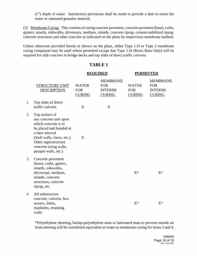
(1”) depth of water. Satisfactory provisions shall be made to provide a dam to retain the water or saturated granular material.
(3) Membrane Curing. This consists of curing concrete pavement, concrete pavement (base), curbs, gutters, retards, sidewalks, driveways, medians, islands, concrete riprap, cement-stabilized riprap, concrete structures and other concrete as indicated on the plans by impervious membrane method. Unless otherwise provided herein or shown on the plans, either Type 1-D or Type 2 membrane curing compound may be used where permitted except that Type 1-D (Resin Base Only) will be required for slab concrete in bridge decks and top slabs of direct traffic culverts. TABLE 1
REQUIRED
PERMITTED
STRUCTURE UNIT DESCRIPTION
WATER FOR CURING
MEMBRANE FOR INTERIM CURING
WATER FOR CURING
MEMBRANE FOR INTERIM CURING
1
Top slabs of direct traffic culverts
X
X
2
Top surface of any concrete unit upon which concrete is to be placed and bonded at a later interval (Stub walls, risers, etc.). Other superstructure concrete (wing walls, parapet walls, etc.)
X
3
Concrete pavement (base), curbs, gutters, retards, sidewalks, driveways, medians, islands, concrete structures, concrete riprap, etc.
X*
X*
4
All substructure concrete, culverts, box sewers, inlets, manholes, retaining walls
X*
X*
*Polyethylene sheeting, burlap-polyethylene mats or laminated mats to prevent outside air from entering will be considered equivalent to water or membrane curing for items 3 and 4.
038000
Page 16 of 19 Rev. 3-25-2015

Membrane curing shall not be applied to dry surfaces, but shall be applied just after free moisture has disappeared. Formed surfaces and surfaces which have been given a first rub shall be dampened and shall be moist at the time of application of the membrane. When membrane is used for complete curing, the film shall remain unbroken for the minimum curing period specified. Membrane which is damaged shall be corrected immediately by reapplication of membrane. Unless otherwise noted herein or on the plans, the choice of membrane type shall be at the option of the Contractor. Only one type of curing compound will be permitted on any one structure. The membrane curing compound shall be applied after the surface finishing has been completed, and immediately after the free surface moisture has disappeared. The surface shall be sealed with a single uniform coating of curing compound applied at the rate of coverage recommended by the manufacturer and directed by the Engineer, but not less than 1 gallon per 180 square feet of area. The Contractor shall provide satisfactory means and facilities to properly control and check the rate of application of the compound. The compound shall be thoroughly agitated during its use and shall be applied by means of approved mechanical power pressure sprayers. The sprayers used to apply the membrane to concrete pavement or concrete pavement (base) shall travel at uniform speed along the forms and be mechanically driven. The equipment shall be of such design that it will insure uniform and even application of the membrane material. The sprayers shall be equipped with satisfactory atomizing nozzles. Only on small miscellaneous items will the Contractor be permitted to use hand-powered spray equipment. For all spraying equipment, the Contractor shall provide facilities to prevent the loss of the compound between the nozzle and the concrete surface during the spraying operations. The compounds shall not be applied to a dry surface. If the surface of the concrete has become dry, it shall be moistened prior to application of membrane by fogging or mist application. Sprinkling or coarse spraying will not be allowed. At locations where the coating shows discontinuities, pinholes or other defects, or if rain falls on the newly-coated surface before the film has dried sufficiently to resist damage, an additional coat of the compound shall be applied immediately at the same rate of coverage specified herein. To insure proper coverage, the Engineer shall inspect all treated areas after application of the compound for the period of time designated in the governing specification for curing, either for membrane curing or for other methods. Should the foregoing indicate that any area during the curing period is not protected, an additional coat or coats of the compound shall be applied immediately, and the rate of application of the membrane compound shall be increased until all areas are uniformly covered. When temperatures are such as to warrant protection against freezing, curing by this method shall be supplemented with an approved insulating material capable of protecting the concrete for the specified curing period. If at any time there is reason to believe that this method of curing is unsatisfactory or is detrimental
038000
Page 17 of 19 Rev. 3-25-2015

to the work, the Contractor, when notified, shall immediately cease the use of this method and shall change to curing by one of the other methods specified under this contract. 15. REMOVAL OF FORMS Except as herein provided, forms for vertical surfaces may be removed when the concrete has aged not less than one day (24 hours) when Type I and Type II cement is used, and not less than one-half day (12 hours) when Type III cement is used, provided it can be done without damage to the concrete. Forms for inside curb faces may be removed in approximately three hours provided it can be done without damage to the curb. 16. FINISHING EXPOSED SURFACES Concrete shall be finished as required in the specification Section for the respective item or as otherwise specified on the plans. An ordinary surface finish shall be applied to all concrete surfaces either as a final finish or preparatory to a higher finish. Ordinary Surface Finish shall be as follows:
After form removal, all porous or honey-combed areas and spalled areas shall be corrected by chipping away all loose or broken material to sound concrete.
Feather edges shall be eliminated by cutting a face perpendicular to the surface. Shallow cavities shall be repaired using adhesive grout or epoxy grout. If judged repairable by the Engineer, large defective areas shall be corrected using concrete or other material approved by the Engineer.
Holes and spalls caused by removal of metal ties, etc., shall be cleaned and filled with adhesive grout or epoxy grout. Exposed parts of metal chairs on surfaces to be finished by rubbing, shall be chipped out to a depth of one-half inch (1/2") and the surface repaired.
All fins, runs, drips or mortar shall be removed from surfaces which remain exposed. Form marks and chamfer edges shall be smoothed by grinding and/or dry rubbing. Grease, oil, dirt, curing compound, etc., shall be removed from surfaces requiring a higher grade of finish. Discolorations resulting from spillage or splashing of asphalt, paint or other similar material shall be removed.
Repairs shall be dense, well bonded and properly cured, and when made on surfaces which remain exposed and do not require a higher finish, shall be finished to blend with the surrounding concrete.
038000
Page 18 of 19 Rev. 3-25-2015

17. MEASUREMENT AND PAYMENT Unless otherwise specified on the Bid Form, no direct measurement or payment will be made for the work to be done or the equipment to be furnished under this specification, but it shall be considered subsidiary to the particular items required by the plans and the contract documents.
038000
Page 19 of 19 Rev. 3-25-2015