Embed Size (px)
Citation preview
ACTAUNIVERSITATIS
UPSALIENSISUPPSALA
2017
Digital Comprehensive Summaries of Uppsala Dissertationsfrom the Faculty of Science and Technology 1588
Features of the Electric FieldsGenerated by Lightning withSpecial Attention to PositiveGround Flashes
DALINA JOHARI
ISSN 1651-6214ISBN 978-91-513-0128-0urn:nbn:se:uu:diva-331885
Dissertation presented at Uppsala University to be publicly examined in Häggsalen,Ångströmlaboratoriet, Lägerhyddsvägen 1, Uppsala, Monday, 11 December 2017 at 13:00 forthe degree of Doctor of Philosophy. The examination will be conducted in English. Facultyexaminer: Prof. Dr. Fridolin Heidler (University of Federal Armed Forces Munich, Germany).
AbstractJohari, D. 2017. Features of the Electric Fields Generated by Lightning with Special Attentionto Positive Ground Flashes. Digital Comprehensive Summaries of Uppsala Dissertations fromthe Faculty of Science and Technology 1588. 49 pp. Uppsala: Acta Universitatis Upsaliensis.ISBN 978-91-513-0128-0.
This thesis focuses on the main processes in positive ground flashes and the distant lightningenvironment for both positive and negative ground flashes. It presents the characteristics of thepreliminary breakdown pulses (PBPs), the characteristics of the electric field pulses observedduring leader propagation, and the characteristics of the electric fields produced by the first andthe subsequent return strokes. It also features the observations of distant positive and negativeground flashes at distances up to 1000 km. The results were based on electric field measurementsconducted remotely during summer thunderstorms in Sweden in 2014.
We found that the majority of the positive ground flashes were preceded by PBPs. Somewere preceded by more than one PBP train, and the parameter values for the subsequent PBPtrains were found to be smaller than the values for the first PBP train. Three types of PBPswere also identified. The results suggest that the PBPs in positive ground flashes during summerthunderstorms in Sweden are weak, and the inverted dipole charge cloud configuration isconsistent with our observation.
A small percentage of these positive ground flashes were observed to be preceded bypronounced leader pulses. The presence of these pulses suggests that the leaders propagate ina stepped manner. We inferred that these pulses were due to the upward-connecting negativeleader since their characteristics were similar to those of a negative stepped leader. On the basisof the leader pulses’ time of initiation and the average speed of the leader, we estimated thedistance travelled by the leader. One case of positive return stroke preceded by negative leaderpulses was also observed, and the occurrence of these pulses was the first in positive groundflashes to be reported.
The majority of these positive ground flashes were found to be single-stroke. Comparisonbetween the first and the subsequent return strokes showed that the average durations of thesubsequent stroke parameters were smaller than that of the first strokes. The distances reportedby the lightning location system suggest that the subsequent strokes probably created newterminations to ground. Two possible reasons were given to explain the reason for the shorterduration of the subsequent return strokes parameters compared to the first strokes.
Finally, observations of distant positive and negative ground flashes showed that the electricfield waveforms have a typical shape, like a distorted ‘W’ (or distorted ‘M’ for negativeground flashes) followed by small oscillations. These small oscillations were more pronouncedin negative ground flashes, especially at a greater distance. The heights of the ionosphericreflections estimated for both ground flashes were found to likely correspond to a D-layer ofthe ionosphere. Two possible reasons were suggested for the small oscillations observed in thewaveforms.
Keywords: positive ground flashes, preliminary breakdown pulses, multiple-trains PBPs,positive leader, bidirectional leader, negative leader branch, subsequent return strokes, distantlightning
Dalina Johari, Department of Engineering Sciences, Electricity, Box 534, Uppsala University,SE-75121 Uppsala, Sweden.
© Dalina Johari 2017
ISSN 1651-6214ISBN 978-91-513-0128-0urn:nbn:se:uu:diva-331885 (http://urn.kb.se/resolve?urn=urn:nbn:se:uu:diva-331885)

To Family

List of Papers
This thesis is based on the following papers, which are referred to in the text by their Roman numerals.
I Johari, D., Cooray, V., Rahman, M., Hettiarachchi, P., and
Ismail, M. M. (2016) Characteristics of preliminary breakdown pulses in positive ground flashes during summer thunderstorms in Sweden. Atmosphere (Basel), 7(3), 39. Part of this work was presented at the 4th International Sympo-sium on Winter Lightning (ISWL) in Joetsu, Japan, 2017.
II Johari, D., Cooray, V., Rahman, M., Hettiarachchi, P. and Ismail, M. M. (2017) Characteristics of leader pulses in positive ground flashes in Sweden. Electric Power Systems Research, 153:3-9. Part of this work was presented at the XIII International Sympo-sium on Lightning Protection (SIPDA) in Balneário Camboriú, Brazil, 2015.
III Johari, D., Cooray, V., Rahman, M., Hettiarachchi, P. and Ismail, M. M. (2017) Features of the first and the subsequent return strokes in positive ground flashes based on electric field measurements. Electric Power Systems Research, 150: 55-62. Part of this work was presented at the 33rd International Confer-ence on Lightning Protection (ICLP) in Estoril, Portugal, 2016.
IV Johari, D. and Cooray, V. (2017) Oscillations observed in bipo-lar electric field from distant cloud-to-ground lightning flashes. Manuscript.
Other contributions of the author, not included in this thesis:
V Johari, D., Cooray, V., Hettiarachchi, P., Rahman, M. and Ismail, M. M., Some characteristics of leader pulses in positive
cloud-to-ground flashes. Proceedings of the XIII International Symposium on Lightning Protection (SIPDA), Balneário Cam-boriú, Brazil, 2015.
VI Johari, D., Cooray, V., Rahman, M., Hettiarachchi, P. and Ismail, M. M., Some characteristics of subsequent return strokes in positive ground flash in Sweden. Proceedings of the 33rd International Conference on Lightning Protection (ICLP), Estoril, Portugal, 2016.
VII Johari, D., Cooray, V., Rahman, M., Hettiarachch, P. and Ismail, M. M., Some features of preliminary breakdown pulses in positive ground flashes in Sweden. Proceedings of the 4th International Symposium on Winter Lightning (ISWL), Joetsu, Japan, 2017.
VIII Ismail, M.M., Rahman, M., Cooray, V., Sharma, S. R., Het-tiarachchi, P. and Johari, D. (2015) Electric field signatures in wide-band, 3 MHz and 30 MHz of negative ground flashes per-tinent to Swedish thunderstorms. Atmosphere, 6(12): 1904-1925.
IX Ismail, M.M., Cooray, V. and Johari, D. (2017) On the zero- crossing time of radiation fields generated by return strokes in lightning flashes. Submitted to Atmosphere.
X Ismail, M.M., Rahman, M., Cooray, V., Fernando, M., Het-tiarachchi, P. and Johari, D. (2017) On the possible origin of chaotic pulse trains in lightning flashes. Atmosphere, 8(2), 29.
XI Ismail, M.M., Sharma, S.R., Cooray, V., Rahman, M., Het-tiarachchi, P. and Johari, D., HF and VHF electric field radiation produced by preliminary breakdown process pertinent to Swe-dish thunderstorms, Proceedings of the 9th Asia-Pacific Interna-tional Conference on Lightning (APL), Nagoya, Japan, 2015.
XII Ismail, M.M., Cooray, V., Rahman, M., Fernando, M., Het-tiarachchi, P. and Johari, D., On the possible origin of chaotic pulse train in lightning flashes, Proceedings of the XIII Interna-tional Symposium on Lightning Protection (SIPDA), Balneário Camboriú, Brazil, 2015.
XIII Ismail, M.M., Cooray, V., Rahman, M., Hettiarachchi, P. and Jo-hari, D., On comparison between initial breakdown pulses and

narrow bipolar pulses in lightning discharges with special atten-tion to electric field derivative characteristics, Proceedings of the 33rd International Conference on Lightning Protection (ICLP), Estoril, Portugal, 2016.
XIV Ismail, M.M., Cooray, V., Rahman, M., Hettiarachchi, P. and Jo-hari, D., Wavelet transform reveals the origin of chaotic pulse train in lightning flashes, Proceedings of the 4th International Symposium on Winter Lightning (ISWL), Joetsu, Japan, 2017.
XV Ismail, M.M., Rahman, M., Cooray, V., Hettiarachchi, P. and Jo-hari, D., Characteristics of chaotic pulse trains associated with dart and dart-stepped leader in lightning flashes in Sweden, Pro-ceedings of the 4th International Symposium on Winter Lightning (ISWL), Joetsu, Japan, 2017.
Reprints were made with permission from the respective publishers.

Contents
1. Introduction .............................................................................................. 13 1.1. Lightning .................................................................................... 13 1.2. Main objectives .......................................................................... 13
2. Background and theory ............................................................................ 16 2.1. General description ..................................................................... 16
2.1.1. Definition and types of lightning ........................................... 16 2.1.2. Thundercloud configurations ................................................. 16 2.1.3. Mechanism of lightning flash ................................................ 17
2.2. Downward positive ground flash ................................................ 19 2.2.1. Characterization of positive ground flash .............................. 20 2.2.2. Discrimination between positive return strokes and cloud
flashes .................................................................................... 21 2.3. Distant lightning ......................................................................... 22
3. Methodology ............................................................................................ 23 3.1. Measurement setup ..................................................................... 23 3.2. Measuring techniques ................................................................. 26
4. Results and discussions ............................................................................ 27 4.1. Characteristics of preliminary breakdown pulses in positive
ground flashes during summer thunderstorms in Sweden (Paper I) ...................................................................................... 27
4.1.1. Summary of results ................................................................ 27 4.1.2. Discussion .............................................................................. 29
4.2. Characteristics of leader pulses in positive ground flashes in Sweden (Paper II) ....................................................................... 31
4.2.1. Summary of results ................................................................ 31 4.2.2. Discussion .............................................................................. 31
4.3. Features of the first and the subsequent return strokes in positive ground flashes based on electric field measurements (Paper III) ................................................................................... 33
4.3.1. Summary of results ................................................................ 34 4.3.2. Discussion .............................................................................. 35
4.4. Oscillations observed in bipolar electric field from distant cloud-to-ground lightning flashes (Paper IV) ............................. 36
4.4.1. Summary of results ................................................................ 36 4.4.2. Discussion .............................................................................. 37

5. Conclusions .............................................................................................. 39 6. Recommendations .................................................................................... 41 Svensk sammanfattning ................................................................................ 42 Acknowledgement ........................................................................................ 44 References ..................................................................................................... 47

Abbreviations
AM Arithmetic Mean GM Geometric Mean GPS Global Positioning System GW Ground Wave IC Intra Cloud kHz kilo Hertz LLS Lightning Location System MeV Mega electron Volt MHz Mega Hertz MS/s Mega Sample per Second MSC Mesoscale Convective System N Sample size PB Preliminary Breakdown PBP Preliminary Breakdown Pulse RLC Resistor (R), Inductor (L) and Capacitor (C) RS Return Stroke SMHI Swedish Meteorological and Hydrological Institute SRS Subsequent Return Stroke
Nomenclature: The term ‘flash’, ‘discharge’ and ‘lightning’ are used inter-changeably in this thesis to describe either cloud lightning or cloud-to-ground lightning.

13
1. Introduction
1.1. Lightning Lightning is an electrical discharge that occurs in the Earth’s atmosphere. At any moment, there are about 100 discharges per second worldwide [1]. Light-ning is commonly associated with thunderclouds but it can also occur in snow-storms and sandstorms and around plumes of erupting volcanoes [2]. During a thunderstorm, as the thunderclouds become charged, large voltages can de-velop between the cloud and the ground or between different parts of the cloud. As the electric field associated with these voltage differences exceeds the critical value necessary for breakdown, electrical discharges take place in the air, leading to a lightning flash. Air is a good insulator in general, but at this critical electric field (i.e. 1.5 x 10⁶ V/m at 5 km above sea level or 3.0 x 10⁶ V/m at sea level [3]), it is converted into a conductor by the cumulative action of avalanches, streamers and leaders, making it capable of conducting electrical currents [4]. The rapid heating of the air to 25,000 to 30,000 K dur-ing a lightning flash causes a rapid increase in the atmospheric pressure, lead-ing to a rapid expansion of the air, creating a shock wave before it transforms into a sound wave known as thunder [5].
Despite being the most observed natural phenomenon in the world, light-ning is still not well understood. Many questions about lightning remain un-answered in spite of recent progress in the area. For example, the most basic question of how lightning is initiated inside the thunderclouds is still being researched, and the physical mechanisms that govern the propagation of dif-ferent types of lightning leaders (e.g. negative stepped, first positive) between the cloud and the ground are still not known [6]. In addition, knowledge of the physics of positive lightning remains poorer than that of negative lightning [7]. These gaps in the knowledge, together with the dangerous threat that light-ning poses, serve as guides and motivation for lightning researchers around the world to continue studying this phenomenon.
1.2. Main objectives The electromagnetic fields generated by the lightning flashes are of im-portance in lightning studies [8]. Features of the electromagnetic fields (e.g. the temporal and spatial variation) can be used to understand the physical
14
mechanism behind the lightning processes while in lightning protection stud-ies, the electromagnetic fields can be used to estimate the voltages and cur-rents induced in structures due to lightning strikes.
The main objectives of the thesis are based on the electric fields generated by the lightning flashes. They are as follows:
i) To characterize the preliminary breakdown pulses of the positive ground flash
The physical mechanism that initiates lightning in the thundercloud is still not well understood. For positive ground flashes, many suggestions have been presented (e.g. [9–15]) but agreement on the initiating mechanisms has not been reached [14]. In addition, information about preliminary breakdown pulses (PBPs) in positive ground flashes is still insufficient compared to information about those in negative ground flashes [16]. Some of these studies did not include statistics on how many positive ground flashes begin with the initial breakdown pulses (e.g. [9],[10]). The study of the preliminary break-down process before positive return strokes is therefore important as it helps to resolve the understanding of the in-cloud process that initiates positive ground flashes. The findings from this study would also add to existing statis-tics of PBP characteristics in positive ground flashes and help to improve our overall understanding of positive ground flashes.
ii) To characterize the leader pulses in positive ground flashes This study is motivated by the fact that very little is known about the downward positive leaders in positive ground flashes [17]. Although plenty of information about negative leaders has been discovered [18], positive leaders are much less studied [6]. Their characteristics are still not well understood [19], and their mode of propagation is still a topic of much interest. The study is therefore essential as the outcome would help to improve our understanding of positive leaders and add to the existing knowledge on positive ground flashes.
iii) To determine the features of the subsequent return strokes in positive ground flashes
Not much knowledge is available in the literature concerning the subsequent return strokes in positive ground flashes. Information about their characteristics, such as the risetime and the zero crossing time, is still lacking, mainly due to the lack of the occurrence of multiple-stroke positive ground flashes. The study is therefore important as it helps to characterize positive subsequent return strokes and provide information for many engineering ap-plications.
15
iv) To determine the source of oscillations observed in bipolar electric field from distant cloud-to-ground lightning flashes
This study involved both the positive and negative ground flashes. It was con-ducted to understand the reason for the appearance of oscillating field change in distant lightning. Compared to close lightning, characteristics of lightning-produced electric fields for distant lightning are influenced by the propagation path of the fields. The possibility that the small oscillations observed in the waveforms come from the low-frequency component of the return stroke cur-rent that oscillates in the lightning channel was investigated. The analysis would be useful to understand the physics behind distant lightning and the interaction of the lightning electromagnetic fields with the ionosphere.
16
2. Background and theory
This chapter gives an overview of the important aspects of positive ground flashes and distant lightning related to the study.
2.1. General description 2.1.1. Definition and types of lightning Lightning can be defined as a transient, high-current electrical discharge of atmospheric origin, whose path length is measured in kilometres [2]. They can be categorized into ground flashes and cloud flashes [20]. Ground flashes make contact with the ground while cloud flashes do not. Depending on the charges being transported to the ground and its point of initiation, a ground flash can further be subdivided into downward and upward ground flashes [20]. Downward ground flash is initiated from the cloud, while upward ground flash is initiated from a tall structure under the influence of the background electric field of the cloud. The polarity of the charges being transported from the cloud to the ground will determine the polarity of the flash, and the point of initiation will determine the direction of the flash. Cloud flashes, on the other hand, occur within a thundercloud, between the thunderclouds and be-tween a thundercloud and clear air. They account for the majority of all light-ning discharges [6],[21]. The term IC (intracloud flash) is often used to refer to all cloud flashes [22].
2.1.2. Thundercloud configurations A typical thundercloud consists of three charged regions [21]. The main pos-itive charge centre is located at the top while the main negative charge centre is located in the middle in a region of −15 to −10 °C isotherm. A smaller pos-itive charge pocket is located below the main negative charge centre. This tripolar structure usually supports the occurrence of intracloud discharges, negative ground flashes and air discharges [23] but not favourable for positive ground flashes [15]. The cloud charge configurations that are found to be more conducive for positive ground flashes are the tilted dipole, the positive mono-pole, the inverted dipole and the unusually large lower positive charge region [15].
17
In a tilted dipole, the upper positive charge region is displaced horizontally from the negative charge region by wind shear. The positive monopolar charge structure is found during the dissipating stage of Japanese winter thunder-clouds, when the negative charge and positive charge carried by the graupel particles fall out of the cloud relatively quickly, leaving behind the positive charge carried by the ice crystals at the main positive charge centre. The in-verted dipole has charge centres with polarity opposite to that found in typical positive dipole thunderclouds, while the unusually large lower positive charge region has a larger-than-usual lower positive charge region.
Two scenarios have also been found to be conducive for positive ground flashes. They are the negative in-cloud leader channel cut-off and the branch-ing of the in-cloud discharge channel [15]. The negative in-cloud leader chan-nel cut-off scenario is found in mesoscale convective systems (MSCs). Nega-tive leaders in IC discharges in MSCs move horizontally for several kilome-tres, and when a negative leader gets cut off, the rear end of the leader channel gets positively charged (i.e. recoil leader is formed) and a positive leader is launched from this rear end of the leader channel, resulting in positive ground flash. Positive ground discharges can also be produced by the branching of the in-cloud discharge channels, most probably when these channels occur near or below the cloud base.
2.1.3. Mechanism of lightning flash i) Lightning initiation Two mechanisms can explain the initiation of lightning in the thunderclouds [18],[24]. One is the classical mechanism, which assumed that the electrical field required to initiate the discharge is caused by the collisions of several charged particles, which increases the electric field briefly to cause the break-down. The other mechanism is the electron runaway breakdown, which pro-posed that the initiation of lightning is due to the acceleration of cosmic-ray-generated high energetic electrons in the thunderstorm’s electric fields to pro-duce an avalanche of MeV electrons.
In the classical mechanism, the initiation of a lightning flash starts with an electrical breakdown in a small region. It requires the electric field in the air to increase beyond the critical electric field (1.5 × 10⁶ V/m at 5 km above sea level). During a thunderstorm, large electric fields are generated within the thundercloud because of the separation of charges in the thundercloud. This electric field is enhanced by the roughly spherical shape of the cloud droplets. During collisions, this field enhancement is increased because several charged particles can act as a single object with an elongated shape [24]. When the electric field exceeds the critical electric field necessary for breakdown, elec-trical breakdown will be initiated in a small region (in the form of a spark).

18
This electrical discharge gives rise to streamer discharges, and when the elec-tric field exceeds 250 kV/m over a region, these streamer discharges propagate and initiate a leader discharge. Once a leader is created, it starts to propagate when the background electric field is about 100 kV/m, leading to either a cloud or a ground flash [24].
ii) Bidirectional propagation of a leader The initiation of a leader in the cloud produces two leader branches. One branch is negatively charged while the other is positively charged. This leads to the leader propagating in two opposite directions. The bidirectional propa-gation of a leader can be explained as follows [24].
In general, the electrical breakdown in the thundercloud leads to the for-mation of a conducting channel. When the conducting channel is exposed to the electric field, opposite charges accumulate at the channel tips. The con-centration of charges increases the electric field at the tips and gives rise to streamer discharges of opposite polarity from the two ends of the conducting channel. This adds length to the leader channel, and the leader channel grows in both directions [24]. The leader then propagates, and this mode of propaga-tion is called a bidirectional propagation.
iii) Recoil leaders As the tip of the positive leader branch moves forward, the conductivity of the channel behind the tip may decrease and result in the cut-off of the current to the tip. As the positive leader branch continues to move forward, negative charges will accumulate at the cut-off point. When the electric field exceeds the critical value for breakdown, a negative leader is initiated at the tip and moves through the cut-off gap, reconnecting the conducting path. According to [24], this negative leader is known as the recoil leader. Even though the mechanism is not fully understood, recoil leaders have been observed during the propagation of some downward positive leaders to ground, in which they were seen to retrace the channel segments that were previously ionized by the positive leader (e.g. [19]).
According to Mazur et al. [25], however, even though the literature defines recoil leaders as negative leaders, recoil leaders should be defined as bipolar and bidirectional leaders. This is because their observations showed that a re-coil leader develops from a small region along a path of the decayed channels of a previous positive leader and propagates initially as a bidirectional and bipolar leader along the now invisible path of that leader. According to them, they were able to observe the positively charged part of one particular recoil leader despite the fact that only the propagation of the negatively charged parts of leaders was highly visible in the majority of their records.
19
iv) Mechanism of negative ground flash The overall lightning discharge is termed a flash, and it involves many physi-cal processes. In general, a downward ground flash is composed of processes such as the preliminary breakdown, stepped leaders, connecting leaders, re-turn strokes, dart leaders, subsequent return strokes, continuing currents and M-components [18].
The most common downward ground flash is the one that lowers negative charges from the thundercloud to the ground. It is called a negative ground flash and is initiated by an electrical breakdown event in the thundercloud called the preliminary breakdown. This breakdown event, which consists of multitudes of discharges, leads to the development of a leader that propagates in a stepped fashion towards the ground. As it propagates, the stepped leader creates branches. When it approaches the ground, the stepped leader induces opposite polarity charges on objects projecting above the earth surface. Since opposite charges attract, these charges attempt to join the downward-moving stepped leader by forming an upward-moving connecting leader. When one of the connecting leaders successfully meets the stepped leader, the charges stored in the thundercloud are released, and the flow of charges towards the ground generates large current in the channel, making the channel glow. A complete conducting path is formed, and a wave of ground potential called the return stroke travels towards the cloud.
The lightning flash may end after the first return current stops flowing, in which case the discharge is called a single-stroke flash. Subsequent return strokes are initiated if additional negative charges are available at the upper portion of the previous stroke channel [6]. When these additional charges are available, a continuously propagating leader known as a dart leader moves down the defunct return stroke channel, depositing negative charges along the channel from the negative charge centre to the ground [6].
The reason that the first return stroke current ceases to flow even though negative charges are still available at the upper portion of the previous stroke channel is probably because of the bidirectional nature of the stepped leader [24]. For negative ground flashes, the cloud-end of the bidirectional leader of the flash is positive, and as the positive leader branch continues to propagate, it will be subjected to current cut-off when the channel behind the leader tip decays. Current will stop flowing but the formation of the recoil leader may reconnect the conducting path, resulting in subsequent return strokes [24].
2.2. Downward positive ground flash A downward positive ground flash is a ground flash that transports positive charges down to earth. Its mechanism is similar to the negative, but positive ground flashes are different in certain aspects [18]. For example, negative
20
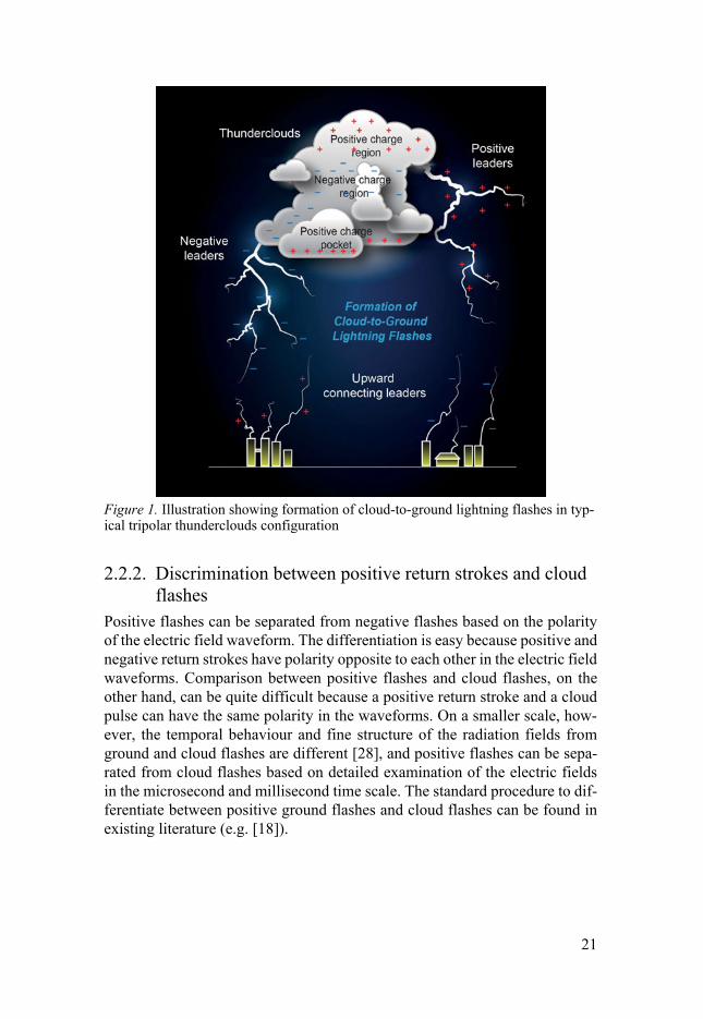
ground flashes lower negative charges from the negative main charge centre while positive ground flashes lower positive charges either from the main up-per positive charge region of the cloud or from the small lower positive charge region. Figure 1 shows the formation of cloud-to-ground lightning flashes in typical tripolar thunderclouds configuration. Compared to downward negative ground flashes, downward positive ground flashes are less dominant and ac-count for only about 10% of global cloud-to-ground lightning [26]. Even though they are less dominant than their negative counterparts, positive ground flashes have attracted attention for several reasons [26].
First, they can produce return strokes with higher peak currents and larger charge transfers, with peak current values reaching up to 300 kA and charges reaching hundreds of coulombs or more. This could potentially cause severe damage to various objects and systems. Second, positive lightning is also the dominant type of cloud-to-ground lightning in certain conditions such as dur-ing the cold season and the dissipating stage of any thunderstorm. Besides winter thunderstorms and the dissipating stage of a thunderstorm, other con-ditions that favour the occurrence of positive ground flashes are the shallow clouds, such as the trailing stratiform regions (i.e. the flat or sheet-like clouds region as opposed to the more vertically developed cumulonimbus cloud re-gion) of an MSC (i.e. thunderstorm clusters); some severe storms; and thun-derclouds formed over forest fires or contaminated by smoke. Third, positive lightning has been found to be related to luminous phenomena in the middle atmosphere known as sprites. Fourth, reliable identification of positive dis-charges by lightning location systems (LLSs) has important consequences for various studies since misidentification of positive return strokes as cloud dis-charges can cause a substantially higher number of positive return strokes to be reported [27].
2.2.1. Characterization of positive ground flash Positive ground flashes have been characterized as having a single stroke in a flash, and the return stroke tends to be followed by a period of continuing currents. Multiple-stroke positive ground flashes, though they do occur, are not as common as multiple-stroke negative ground flashes. According to [24], the reason for the single-stroke nature of the positive ground flashes could be that the cloud-end of the bidirectional leader of the flash is negative; since negative leaders are not hindered by current cut-off, current continues to flow along the channel (and hence, the continuing current) until the charges in the positive charge centre are depleted. Positive ground flashes are also normally observed to be preceded by significant in-cloud discharge activity, often in-volve long horizontal channels up to tens of kilometres, and have leaders that appear to move either continuously or in a stepped fashion [6],[26].
21
Figure 1. Illustration showing formation of cloud-to-ground lightning flashes in typ-ical tripolar thunderclouds configuration
2.2.2. Discrimination between positive return strokes and cloud flashes
Positive flashes can be separated from negative flashes based on the polarity of the electric field waveform. The differentiation is easy because positive and negative return strokes have polarity opposite to each other in the electric field waveforms. Comparison between positive flashes and cloud flashes, on the other hand, can be quite difficult because a positive return stroke and a cloud pulse can have the same polarity in the waveforms. On a smaller scale, how-ever, the temporal behaviour and fine structure of the radiation fields from ground and cloud flashes are different [28], and positive flashes can be sepa-rated from cloud flashes based on detailed examination of the electric fields in the microsecond and millisecond time scale. The standard procedure to dif-ferentiate between positive ground flashes and cloud flashes can be found in existing literature (e.g. [18]).
22
2.3. Distant lightning The electric fields produced by lightning vary depending upon the distance of the lightning channel from the measuring station. For relatively close electric fields, the characteristics are determined mainly by the characteristics of the currents in the lightning flash. At these ranges (less than a few hundred km), the fields propagate from the lightning source to the observation point either by means of a ground wave in the atmosphere along the finitely conducting Earth boundary or by line of sight directly through the atmosphere. On the other hand, characteristics of distant electric fields at distances ranging from a few hundreds to thousands of kilometres are influenced by the propagation path of the fields [29],[30].
In general, propagation effect is the attenuation of the electromagnetic wave due to the absorption of energy from the electromagnetic field by the finitely conducting ground [31]. The amount of energy absorbed by the ground will be higher if the frequency of the electromagnetic field is higher. For per-fectly (i.e. infinitely) conducting ground, the amplitude of the electric field decreases inversely with distance. However, if the ground is finitely conduct-ing, the amplitude of the field decreases much more rapidly than does the in-verse distance. Since the rate of decrease of the wave is higher if the ground is finitely conducting, the effect will be much more pronounced for electric fields at greater distance. Hence, the electric fields from distant lightning are much more influenced by the propagation effect than lightning at closer dis-tances.
One of the observed signals from distant lightning flashes are called atmos-pherics or sferics [30]. They propagate in a waveguide mode in the spherical Earth-ionosphere cavity by means of multiple reflections, and at a given range, consist of a ground wave and a sequence of sky waves. Typical frequency of sferics ranges between 3 kHz – 30 kHz and their waveforms show different characteristics during night and day time due to the different properties of the ionosphere during the two periods of time [30].
23
3. Methodology
This chapter provides an overview of the measurement setup and techniques used in the study. For further description regarding the antenna systems, buffer electronic circuits and system calibration, see Ref [32]. Refs [33,34] are also recommended for further reading because the measurement setups used in those studies were identical to those used in our study.
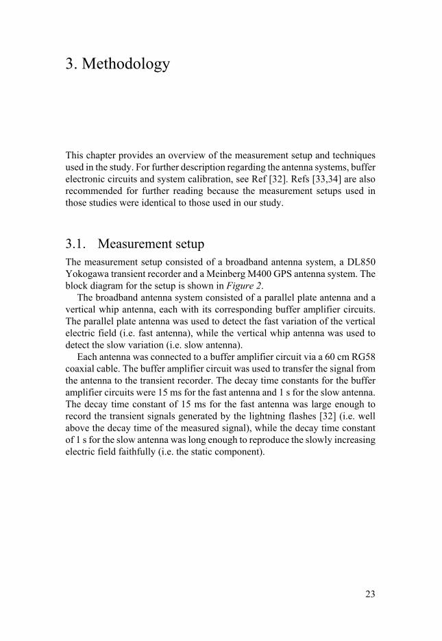
3.1. Measurement setup The measurement setup consisted of a broadband antenna system, a DL850 Yokogawa transient recorder and a Meinberg M400 GPS antenna system. The block diagram for the setup is shown in Figure 2.
The broadband antenna system consisted of a parallel plate antenna and a vertical whip antenna, each with its corresponding buffer amplifier circuits. The parallel plate antenna was used to detect the fast variation of the vertical electric field (i.e. fast antenna), while the vertical whip antenna was used to detect the slow variation (i.e. slow antenna).
Each antenna was connected to a buffer amplifier circuit via a 60 cm RG58 coaxial cable. The buffer amplifier circuit was used to transfer the signal from the antenna to the transient recorder. The decay time constants for the buffer amplifier circuits were 15 ms for the fast antenna and 1 s for the slow antenna. The decay time constant of 15 ms for the fast antenna was large enough to record the transient signals generated by the lightning flashes [32] (i.e. well above the decay time of the measured signal), while the decay time constant of 1 s for the slow antenna was long enough to reproduce the slowly increasing electric field faithfully (i.e. the static component).
24
Figure 2. Block diagram for the measurement setup
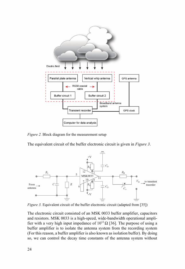
The equivalent circuit of the buffer electronic circuit is given in Figure 3.
Figure 3. Equivalent circuit of the buffer electronic circuit (adapted from [35])
The electronic circuit consisted of an MSK 0033 buffer amplifier, capacitors and resistors. MSK 0033 is a high-speed, wide-bandwidth operational ampli-fier with a very high input impedance of 1012 Ω [36]. The purpose of using a buffer amplifier is to isolate the antenna system from the recording system (For this reason, a buffer amplifier is also known as isolation buffer). By doing so, we can control the decay time constants of the antenna system without

25
affecting the recording part of the system, and we can terminate the RG58 cable connected to the transient recorder with a 50 Ω resistor (to avoid reflec-tion) without affecting the decay time constants of the antenna system. The buffer amplifier can also be used to provide amplification of the signal gener-ated by the antenna but in our case, the amplification was set to unity.
The values of the components used are as follows:
R1 = 50 Ω, C = 15 pF for the fast antenna, 10 nF for the slow antenna, R = 100 MΩ, Rb = 100 Ω, Cb = 0.1 pF, R0 = 43 Ω, Cv = 10 – 60 pF
The R1 value was selected to match the RG58 cable’s characteristic impedance of 50 Ω. The R and C values determine the cut-off frequency of the filter and the decay time constant of the whole system. Rb and Cb are components for the operational amplifier power-supply-bypassing to avoid power-supply-in-duced oscillation. The R0 and Cv are components for impedance matching with the cable connected to the transient recorder. Since the output impedance of the buffer is about 7 Ω (i.e. buffer is connected in series with R0), the R0 value was selected to be 43 Ω to match the 50 Ω cable’s characteristic impedance.
On the basis of the calibration work done previously by Galvan and Fer-nando [32], the relationship between the background electric field En and the measured voltage Vm for physical height of 1.5 m and corresponding effective height of 0.27 m for the parallel-plate antenna is given by:
( )16.20 mn VE =
Signals from the buffer amplifier circuits were fed into the transient recorder by using RG58 coaxial cables. Since RG58 has a 50 Ω characteristic imped-ance, each cable was terminated with a 50 Ω resistor to avoid reflections. To avoid any distortion to the electric field, the antennae were located far from the recording instrument. For this purpose, long coaxial cables of about 10 to 15 m were used.
The transient recorder was used to record the electric fields generated by the lightning flashes. It is a high-speed, high-resolution recorder, with a sam-pling rate of 100 MS/s at 10 ns interval and 12-bit resolution. The high-speed and high-resolution features of the transient recorder ensure that the fast fea-tures of the electric field waveforms can be recorded faithfully [18]. The GPS antenna system provided timing information for each of the recorded electric fields. The whole system had a bandwidth from a few Hz to about 100 MHz.
26
3.2. Measuring techniques Measurements of the electric fields generated by the cloud-to-ground light-ning flashes were carried out in Uppsala, Sweden (59.837°N, 17.646°E) from June to August of 2014 during the summer. They were conducted at a station close to the Ångström Laboratory, Division of Electricity, Uppsala University.
The recording length was set to 1 s to ensure that the whole activity perti-nent to a lightning flash would be captured. The transient recorder was set to work in a pretrigger mode at 20% of the 1 s recording length. The transient recorder was triggered automatically based on the voltage amplitude of the incoming signal from the parallel plate antenna. The electric field records were GPS time-stamped with 1 µs accuracy.
For close lightning measurement, the trigger level was set above noise level at a 50 mV minimum. During the measurement period, the trigger level was changed depending on how close the thunderstorm was, monitored through the Swedish Meteorological and Hydrological Institute (SMHI) website and observations at the site. When the thunderstorms were close to the station, a higher trigger level was set in an attempt to ensure close flashes would be recorded. For distant lightning measurements, the trigger level was set slightly above the noise level to capture very distant lightning.
The atmospheric sign convention was used, according to which a down-ward-directed electric field is considered to be positive. For details regarding the sample size and selection criteria used in each study, see Papers I to IV.
27
4. Results and discussions
This chapter gives a summary of the research work. It covers the main pro-cesses in positive ground flashes such as the preliminary breakdown, the leader propagation and the first and subsequent return strokes. The work also covers the distant lightning environment of both positive and negative ground flashes.
4.1. Characteristics of preliminary breakdown pulses in positive ground flashes during summer thunderstorms in Sweden (Paper I)
Positive ground flash is normally preceded by a significant in-cloud discharge activity that lasts more than 100 ms [26]. This initial breakdown, often referred to as preliminary breakdown, is an important in-cloud process that leads, in the case of negative ground flashes, to the initiation of the downward-moving stepped leaders [37]. In the case of negative ground flashes, it is usually as-sumed to be a result of electrical breakdown between the negative charge cen-tre and the lower positive charge pocket. In the case of positive ground flashes, the physical process that leads to the preliminary breakdown is still not well understood and information on the features of PBPs in positive ground flashes is still insufficient [16]. With these goals in mind, we analysed 51 positive ground flashes obtained from remote electric field measurement.
4.1.1. Summary of results The 51 positive ground flashes analysed were located at distances 6 to 130 km from the measurement station.
i) Detection and classification of the PBP It was found that the majority (86%) of the positive ground flashes were pre-ceded by PBP trains. Depending on the number of trains preceding the first return stroke, the PBP trains could be classified into single (84%) and multiple (16%). Figure 4 shows for the sample waveforms for the different types of the PBPs.
28
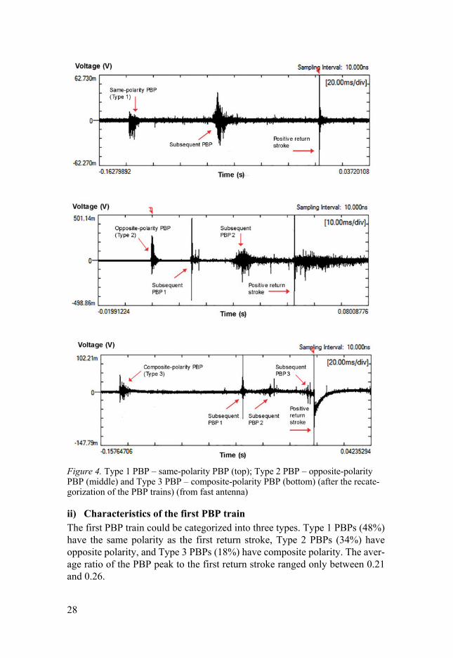
Figure 4. Type 1 PBP – same-polarity PBP (top); Type 2 PBP – opposite-polarity PBP (middle) and Type 3 PBP – composite-polarity PBP (bottom) (after the recate-gorization of the PBP trains) (from fast antenna)
ii) Characteristics of the first PBP train The first PBP train could be categorized into three types. Type 1 PBPs (48%) have the same polarity as the first return stroke, Type 2 PBPs (34%) have opposite polarity, and Type 3 PBPs (18%) have composite polarity. The aver-age ratio of the PBP peak to the first return stroke ranged only between 0.21 and 0.26.

29
For each type, the temporal characteristics of the PBP, such as the time interval between the largest PBP and the first return stroke, the pulse train duration, the interpulse duration, the individual pulse duration and the total pulse duration, were obtained. For Type 1, Type 2 and Type 3, the PBP–return stroke separations were 75.1 ms, 114.6 ms and 59.2 ms; the pulse train dura-tions were 5.9 ms, 2.6 ms and 24.8 ms; and the interpulse durations were 115.1 µs, 93.7 µs and 57.2 µs, respectively. For individual pulse duration, the aver-age values for the first half-cycle for Type 1, Type 2 and Type 3 were 8.2 µs, 3.8 µs and 4.9 µs; for the second half-cycle the values were 10.0 µs, 7.3 µs and 8.3 µs; and the total pulse durations were 16.9 µs, 10.0 µs and 12.8 µs, respectively.
iii) Characteristics of the subsequent PBP trains Compared to the first PBP train (overall), the parameter values for the subse-quent PBP trains were smaller. The PBP peak amplitude relative to the return stroke peak was only 0.14. The time intervals between the largest PBP and the first return stroke, pulse train duration, individual pulse duration and inter-pulse duration for the subsequent PBP trains were 73.23 ms, 3.63 ms, 11.05 µs and 43.78 µs, respectively.
4.1.2. Discussion Initially, we considered pulse bursts that have a duration of the order of a mil-lisecond as the PBP train, while other pulse bursts with longer train duration were categorized as IC discharges. This gave us 84% single-train PBPs and 16% multiple-trains PBPs. However, the categorization may not be accurate considering that all of these discharges probably occurred in the cloud and were observed to precede the first return stroke in the electric field waveforms. On this basis, we recategorized the PBP trains, which gave us only 39% sin-gle-train PBPs and 61% multiple-trains PBPs (see Paper VII). For the single-train PBP category, only one PBP train was observed preceding the first return stroke. For the case of multiple-trains PBPs, up to four PBP trains were ob-served to precede the first return stroke. We assumed that the multiple-trains PBPs belonged to the same positive ground flash since no other ground flashes were present in the electric field waveform. In cases where multiple-trains PBPs were observed, the last PBP train was probably the one that led to the return stroke.
The average ratio of the PBP peak to the first return stroke indicates the strength of the PBP. Since the mean values for all three types are less than half, PBPs in Sweden can be considered weak. PBPs with amplitudes smaller than these might not be detected by the measurement system. This could be the reason for the nondetection of PBPs in some of the positive ground flashes. In addition, if the PBP trains occurred outside the pretrigger setting of the transient recorder, they would also have been missed.
30
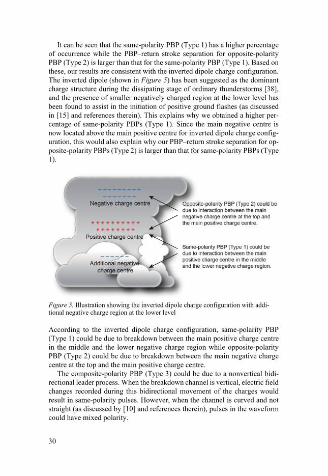
It can be seen that the same-polarity PBP (Type 1) has a higher percentage of occurrence while the PBP–return stroke separation for opposite-polarity PBP (Type 2) is larger than that for the same-polarity PBP (Type 1). Based on these, our results are consistent with the inverted dipole charge configuration. The inverted dipole (shown in Figure 5) has been suggested as the dominant charge structure during the dissipating stage of ordinary thunderstorms [38], and the presence of smaller negatively charged region at the lower level has been found to assist in the initiation of positive ground flashes (as discussed in [15] and references therein). This explains why we obtained a higher per-centage of same-polarity PBPs (Type 1). Since the main negative centre is now located above the main positive centre for inverted dipole charge config-uration, this would also explain why our PBP–return stroke separation for op-posite-polarity PBPs (Type 2) is larger than that for same-polarity PBPs (Type 1).
Figure 5. Illustration showing the inverted dipole charge configuration with addi-tional negative charge region at the lower level
According to the inverted dipole charge configuration, same-polarity PBP (Type 1) could be due to breakdown between the main positive charge centre in the middle and the lower negative charge region while opposite-polarity PBP (Type 2) could be due to breakdown between the main negative charge centre at the top and the main positive charge centre.
The composite-polarity PBP (Type 3) could be due to a nonvertical bidi-rectional leader process. When the breakdown channel is vertical, electric field changes recorded during this bidirectional movement of the charges would result in same-polarity pulses. However, when the channel is curved and not straight (as discussed by [10] and references therein), pulses in the waveform could have mixed polarity.

31
4.2. Characteristics of leader pulses in positive ground flashes in Sweden (Paper II)
Another observed property associated with positive ground flashes is the prop-agation of the leaders that appear to move either continuously or in a stepped manner [26]. Stepping means the leader channel appears bright during leader formation but remains dark in between step formation [18]. Positive leaders exhibit a continuously bright channel image, either without such steps or with superimposed steps in the form of luminosity enhancements [26]. This mode of propagation of the leaders is still a topic of much interest and since their characteristics are still not well understood [19], it has motivated us to under-take the study.
4.2.1. Summary of results The study involved 51 positive ground flashes located at distances 6 to 130 km from the measurement station.
i) Percentage of detection In our study, pronounced leader pulses were observed in 22% of the cases.
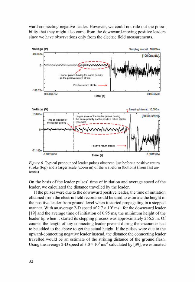
ii) Characteristics of pronounced leader pulses We found that the leader pulses appeared 0.26 to 1.40 ms before the following first return stroke with an average of 0.95 ms. The peak amplitude of the leader pulses relative to the return stroke peak ranged between 2.7 and 17.8% of the return stroke peak with an average of 6.4%. The interpulse duration between successive pulses just before the first return stroke ranged between 13.3 and 50.3 µs with a mean of 24.7 µs. Figure 6 shows typical pronounced leader pulses observed just before a positive return stroke.
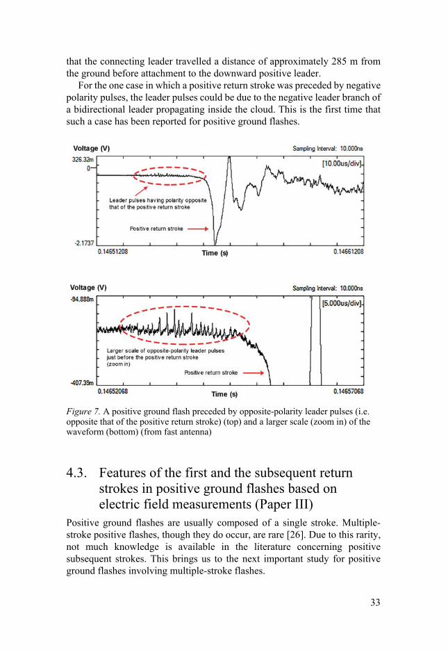
iii) Opposite-polarity leader pulses One case of positive ground flash preceded by opposite-polarity leader pulses just before the return stroke was also observed (shown in Figure 7). They were observed to start 0.02 ms before the following return stroke; the interpulse duration was 1.78 µs, and the peak amplitude was 3.77% of the return stroke peak.
4.2.2. Discussion The presence of these leader pulses suggests that the leaders propagate in a stepped manner. Since their characteristics were similar to those of a negative stepped leader [39–42], we inferred that these pulses could be due to the up-
32
ward-connecting negative leader. However, we could not rule out the possi-bility that they might also come from the downward-moving positive leaders since we have observations only from the electric field measurements.
Figure 6. Typical pronounced leader pulses observed just before a positive return stroke (top) and a larger scale (zoom in) of the waveform (bottom) (from fast an-tenna)
On the basis of the leader pulses’ time of initiation and average speed of the leader, we calculated the distance travelled by the leader.
If the pulses were due to the downward positive leader, the time of initiation obtained from the electric field records could be used to estimate the height of the positive leader from ground level when it started propagating in a stepped manner. With an average 2-D speed of 2.7 × 10⁵ ms-1 for the downward leader [19] and the average time of initiation of 0.95 ms, the minimum height of the leader tip when it started its stepping process was approximately 256.5 m. Of course, the length of any connecting leader present during the encounter had to be added to the above to get the actual height. If the pulses were due to the upward-connecting negative leader instead, the distance the connecting leader travelled would be an estimate of the striking distance of the ground flash. Using the average 2-D speed of 3.0 × 10⁵ ms-1 calculated by [39], we estimated
33
that the connecting leader travelled a distance of approximately 285 m from the ground before attachment to the downward positive leader.
For the one case in which a positive return stroke was preceded by negative polarity pulses, the leader pulses could be due to the negative leader branch of a bidirectional leader propagating inside the cloud. This is the first time that such a case has been reported for positive ground flashes.
Figure 7. A positive ground flash preceded by opposite-polarity leader pulses (i.e. opposite that of the positive return stroke) (top) and a larger scale (zoom in) of the waveform (bottom) (from fast antenna)
4.3. Features of the first and the subsequent return strokes in positive ground flashes based on electric field measurements (Paper III)
Positive ground flashes are usually composed of a single stroke. Multiple-stroke positive flashes, though they do occur, are rare [26]. Due to this rarity, not much knowledge is available in the literature concerning positive subsequent strokes. This brings us to the next important study for positive ground flashes involving multiple-stroke flashes.
34
4.3.1. Summary of results In our study, 51 positive ground flashes containing 51 first strokes and nine subsequent strokes were analysed. They were located at distances 6 to 150 km from the measurement station.
i) Flash multiplicity, interstroke intervals and distance between strokes
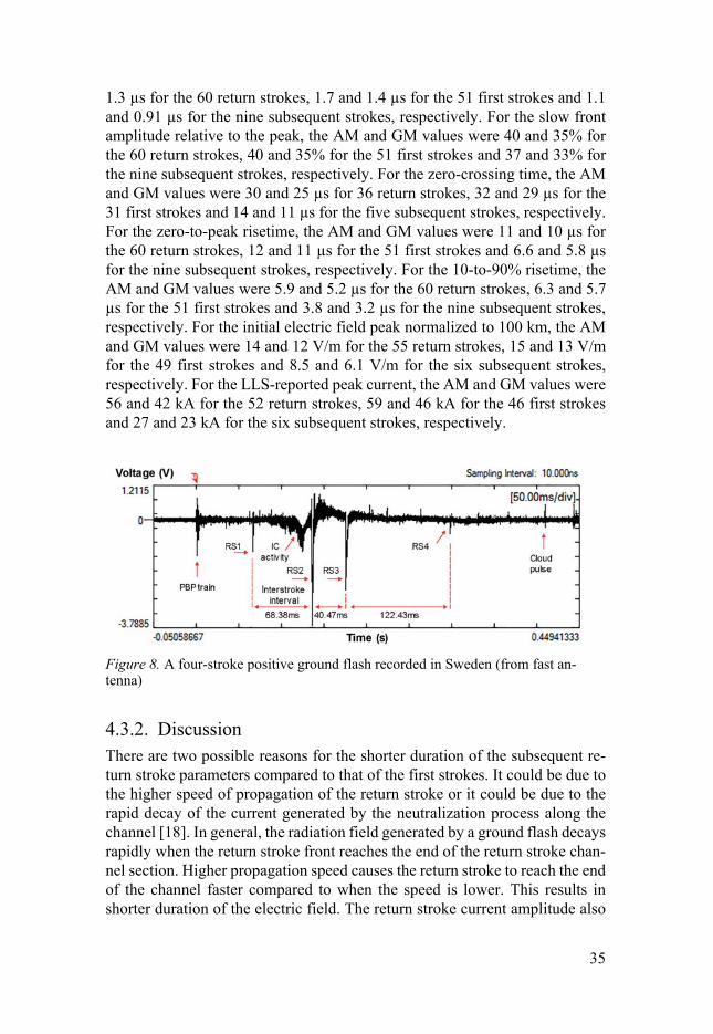
We found that the majority of the positive ground flashes were single-stroke and only 12% were multiple-stroke. Flash multiplicity was 1.20, and the high-est number of strokes per flash recorded was four. Figure 8 shows a four-stroke positive ground flash recorded during the measurement. For the nine subsequent strokes, the geometric mean (GM) value of the interstroke interval was 60 ms while the LLS-reported distance between the first and the subse-quent strokes ranged between 4.9 and 46.4 km. Since we did not have any video recordings, we were not able to determine whether the subsequent stroke followed the previously formed channel of the return stroke or created a new termination on ground. However, the LLS-reported distances suggest that the subsequent strokes created new terminations to ground.
ii) Return stroke parameters We also found that, in comparison, the average durations of the subsequent return strokes parameters were shorter than that of the first strokes. The results are summarized in Table 1.
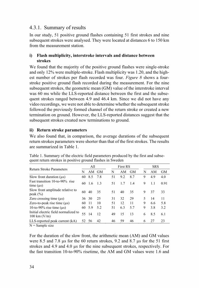
Table 1. Summary of the electric field parameters produced by the first and subse-quent return strokes in positive ground flashes in Sweden
Return Stroke Parameters All First RS SRS
N AM GM N AM GM N AM GM Slow front duration (µs) 60 8.5 7.8 51 9.2 8.7 9 4.9 4.0 Fast transition 10-to-90% rise time (µs) 60 1.6 1.3 51 1.7 1.4 9 1.1 0.91
Slow front amplitude relative to peak (%) 60 40 35 51 40 35 9 37 33
Zero crossing time (µs) 36 30 25 31 32 29 5 14 11 Zero-to-peak rise time (µs) 60 11 10 51 12 11 9 6.6 5.8 10-to-90% rise time (µs) 60 5.9 5.2 51 6.3 5.7 9 3.8 3.2 Initial electric field normalized to 100 km (V/m) 55 14 12 49 15 13 6 8.5 6.1
LLS-reported peak current (kA) 52 56 42 46 59 46 6 27 23 N = Sample size
For the duration of the slow front, the arithmetic mean (AM) and GM values were 8.5 and 7.8 µs for the 60 return strokes, 9.2 and 8.7 µs for the 51 first strokes and 4.9 and 4.0 µs for the nine subsequent strokes, respectively. For the fast transition 10-to-90% risetime, the AM and GM values were 1.6 and
35
1.3 µs for the 60 return strokes, 1.7 and 1.4 µs for the 51 first strokes and 1.1 and 0.91 µs for the nine subsequent strokes, respectively. For the slow front amplitude relative to the peak, the AM and GM values were 40 and 35% for the 60 return strokes, 40 and 35% for the 51 first strokes and 37 and 33% for the nine subsequent strokes, respectively. For the zero-crossing time, the AM and GM values were 30 and 25 µs for 36 return strokes, 32 and 29 µs for the 31 first strokes and 14 and 11 µs for the five subsequent strokes, respectively. For the zero-to-peak risetime, the AM and GM values were 11 and 10 µs for the 60 return strokes, 12 and 11 µs for the 51 first strokes and 6.6 and 5.8 µs for the nine subsequent strokes, respectively. For the 10-to-90% risetime, the AM and GM values were 5.9 and 5.2 µs for the 60 return strokes, 6.3 and 5.7 µs for the 51 first strokes and 3.8 and 3.2 µs for the nine subsequent strokes, respectively. For the initial electric field peak normalized to 100 km, the AM and GM values were 14 and 12 V/m for the 55 return strokes, 15 and 13 V/m for the 49 first strokes and 8.5 and 6.1 V/m for the six subsequent strokes, respectively. For the LLS-reported peak current, the AM and GM values were 56 and 42 kA for the 52 return strokes, 59 and 46 kA for the 46 first strokes and 27 and 23 kA for the six subsequent strokes, respectively.
Figure 8. A four-stroke positive ground flash recorded in Sweden (from fast an-tenna)
4.3.2. Discussion There are two possible reasons for the shorter duration of the subsequent re-turn stroke parameters compared to that of the first strokes. It could be due to the higher speed of propagation of the return stroke or it could be due to the rapid decay of the current generated by the neutralization process along the channel [18]. In general, the radiation field generated by a ground flash decays rapidly when the return stroke front reaches the end of the return stroke chan-nel section. Higher propagation speed causes the return stroke to reach the end of the channel faster compared to when the speed is lower. This results in shorter duration of the electric field. The return stroke current amplitude also
36
decays as it propagates along the channel, in general. A rapid decay of this current makes the duration of the return stroke electric field shorter. This could be the second reason for the shorter duration of the subsequent return stroke parameters in the electric field waveforms.
4.4. Oscillations observed in bipolar electric field from distant cloud-to-ground lightning flashes (Paper IV)
Characteristics of lightning-generated electric fields vary depending upon the distance of the lightning channel from the measuring station. For close light-ning, the characteristics are determined by the characteristics of the lightning current but for distant lightning, the characteristics are significantly influenced by the propagation path of the fields [29],[30]. In order to investigate the rea-son for the appearance of oscillating field change in distant lightning, we con-sidered both the positive and negative ground flashes at distances up to 1000 km.
4.4.1. Summary of results The analysis involved 34 positive ground flashes located at distances 117 to 411 km and 34 negative ground flashes located at distances 366 to 971 km from the measurement station.
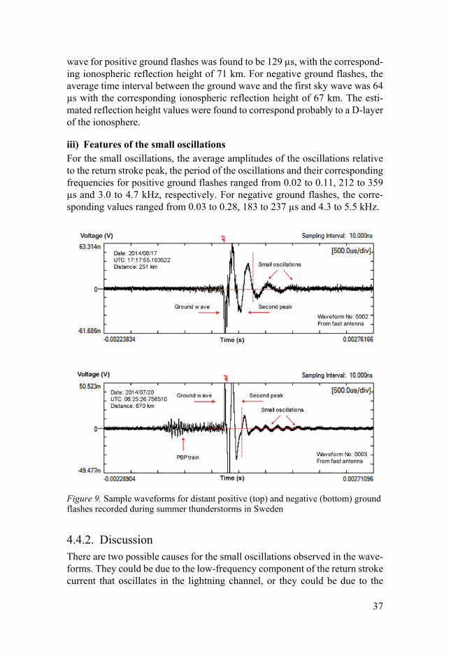
i) General observations The electric field waveforms were observed to have a typical shape like a dis-torted ‘W'’ (or a distorted ‘M’ for negative ground flashes) followed by small oscillations. Sample waveforms are shown in Figure 9. The oscillations started after the second peak and were more pronounced in negative ground flashes, especially at greater distances. For negative ground flashes, 74% had SRS and they showed wave shapes similar to those of the first return strokes. None of the positive ground flashes analysed, however, had any SRS. In both the positive and negative ground flashes, PBP trains were observed in 71% of the cases. For positive ground flashes, the average time separations between the largest PBP and the ground wave were much larger (17.8 ms for same-polarity PBP and 36.7 ms for opposite-polarity PBP) compared to that of the negative ground flashes (2.6 ms).
ii) Ionospheric reflections On the basis of the difference in time of arrivals of the ground wave and the first sky wave, we estimated the ionospheric reflections heights for both flashes. The average time interval between the ground wave and the first sky
37
wave for positive ground flashes was found to be 129 µs, with the correspond-ing ionospheric reflection height of 71 km. For negative ground flashes, the average time interval between the ground wave and the first sky wave was 64 µs with the corresponding ionospheric reflection height of 67 km. The esti-mated reflection height values were found to correspond probably to a D-layer of the ionosphere.
iii) Features of the small oscillations For the small oscillations, the average amplitudes of the oscillations relative to the return stroke peak, the period of the oscillations and their corresponding frequencies for positive ground flashes ranged from 0.02 to 0.11, 212 to 359 µs and 3.0 to 4.7 kHz, respectively. For negative ground flashes, the corre-sponding values ranged from 0.03 to 0.28, 183 to 237 µs and 4.3 to 5.5 kHz.
Figure 9. Sample waveforms for distant positive (top) and negative (bottom) ground flashes recorded during summer thunderstorms in Sweden
4.4.2. Discussion There are two possible causes for the small oscillations observed in the wave-forms. They could be due to the low-frequency component of the return stroke current that oscillates in the lightning channel, or they could be due to the

38
filtering of the frequencies by the Earth-ionosphere waveguide. Using a trans-mission line model to represent the return stroke and a simple RLC circuit analysis to calculate the frequency, we estimated the frequency of oscillations as around 2.5 to 5 kHz, which suggests that the oscillations observed in the waveform may come from the low-frequency component of the current that oscillates in the return stroke channel. The gradual decrease of the amplitude seen in the waveform is probably due to channel resistance and mismatching. Another possible cause for the small oscillations is the filtering of the frequen-cies by the waveguide. Since sferics propagate in a waveguide mode, they cannot contain frequency components below 1 to 3 kHz as this is the cut-off frequency of the Earth-ionosphere waveguide [30].
39
5. Conclusions
Conclusions based on our findings are as follows:
i) Paper I We concluded that the nondetection of PBPs in some of the positive ground flashes could be due to the relatively small PBP amplitude below noise level and their occurrence outside the pretrigger setting of the transient recorder. Second, the PBPs in positive ground flashes in summer thunderstorms in Swe-den are weak on average since the ratio of the PBP peak to the first return stroke peak lies only between 0.21 and 0.26. Third, the inverted dipole cloud configuration is consistent with our observation. Same-polarity PBP (Type 1) could be due to the interaction between the main positive charge centre in the middle and the lower negative charge region while opposite-polarity PBP (Type 2) could be due to the interaction between the main negative charge centre at the top and the main positive charge centre. The composite-polarity PBP (Type 3) could be due to the bidirectional leader process in a nonvertical channel.
ii) Paper II The presence of the leader pulses before the positive return strokes suggests that the leaders propagate in a stepped manner. Since their characteristics were found to be similar to those of a negative stepped leader [39],[40],[41],[42], we inferred that these pulses result from the upward-connecting negative leader. However, we could not rule out the possibility that the pulses could also be due to the stepping of downward positive leaders since we only have electric field measurements. Based on the leader pulses’ time of initiation and average speed of the leader, the distance travelled by the leader could be esti-mated. If the pulses were due to the downward positive leader, the time of initiation of the pulses obtained from the electric field records could be used to estimate the height of the leader when the pulsation began. If, however, the pulses were due to the upward-connecting negative leader, the distance the connecting leader travelled would be an estimate of the striking distance of the ground flash. One case of positive ground flash preceded by negative leader pulses just before the return stroke was also observed. Interestingly, this is the first time that such a case in positive ground flashes has been reported. These pulses could be due to the negative leader branch of a bidirectional leader inside the cloud that propagates towards the observation point.
40
iii) Paper III Next, we found that indeed the majority of the positive ground flashes were single-stroke. Only 12% of the positive ground flashes were multiple-stroke, and flash multiplicity was 1.20. For the nine subsequent strokes, the GM value of the interstroke interval was 60 ms while the LLS-reported distance between the first and the subsequent strokes ranged between 4.9 and 46.4 km. The LLS-reported distances suggest that the subsequent strokes created new termina-tions to ground. The shorter duration of the subsequent return strokes param-eters compared to the first strokes could be due to two reasons. It could be due to the higher speed of propagation of the return stroke or it could be due to the rapid decay of the current generated by the neutralization process along the channel [18].
iv) Paper IV Besides the lightning processes, our study also involved the distant lightning environment. Our observations of distant positive and negative ground flashes showed that the electric field waveforms from ground flashes at distances up to 1000 km have a typical shape like a ‘W’ (or an ‘M’ for negative ground flashes) followed by small oscillations. Compared to positive ground flashes, the oscillations were more pronounced in negative ground flashes. We suggest that the small oscillations observed in the waveforms come from the low-fre-quency component of the return stroke current that oscillates in the lightning channel. We used a transmission line model to represent the return stroke and a simple RLC circuit analysis to calculate the frequency, and the frequency values estimated suggest that the oscillations seen in the waveform may come from the low-frequency component of the current that oscillates in the return stroke channel, with the gradual decrease of the current amplitude due to chan-nel resistance and mismatching. Another possible cause of oscillations is the filtering of the signal frequencies by the propagation through the Earth-iono-sphere waveguide.
41
6. Recommendations
Recommendations based on each paper are as follows:
i) Paper I For future study, it is recommended that the pretrigger setting of the transient recorder be increased to a value greater than 200 ms to improve the possibility of capturing all PBPs. To support the inverted dipole cloud configuration hy-pothesis, further investigation is required.
ii) Papers II and III The use of high-speed video cameras would be essential to provide additional support to the electric field measurements. The data can be used to trace and observe the paths followed by the leaders and can also be used to determine the termination points on the ground made by each subsequent return stroke.
iii) Paper IV More observations and in-depth analysis are required to support the hypothe-sis that the oscillating field change observed in the distant lightning is due to the low-frequency component of the return stroke current that oscillates in the lightning channel.
42
Svensk sammanfattning
Avhandlingen lägger sin fokus på huvudprocesserna som sker i en positiv jordblixt och det avlägsna elektromagnetiska fältmiljön genererat av både po-sitiv och negativ jordblixt. Den presenterar egenskaperna hos i) förberedande sammanbrottspulserna (PBPs), ii) elektriska fältpulserna observerade under uppbyggnaden av blixtkanalen, och iii) elektriska fälten som produceras av de första och de efterföljande huvudurladdningarna. Den karaktäriserar också ob-servationer av avlägsna positiva och negativa jordblixtar vid avstånd upp till 1000 km. Resultaten har baserats på elektriska fältmätningar som utfördes på avstånd under sommar åskväder i Sverige år 2014.
Från studien fann vi att majoriteten av de positiva jordblixtrar föregicks av PBPs. Några föregicks av mer än en PBP-kedja, och parametervärdena för de efterföljande PBP-kedjorna visade sig vara mindre än det för det första PBP-kedja. Tre typer av PBPs kunde identifieras, baserat på pulsens polaritet i för-hållande till huvudurladdningen. Resultaten tyder på att PBPs i de positiva jordblixtarna som inträffade under sommar åskvädret i Sverige är svaga, och den inverterade dipol-formade laddningskonfigurationen av molnet överens-stämmer med våra observationer.
Likafullt, en liten andel av dessa positiva jordblixtrar som observerades fö-regicks av tydliga förurladdningspulser. Förekomsten av dessa pulser tyder på att förurladdningarna propagerar i steg. Deras egenskaper visade sig likna dem hos negativa stegurladdningar, så att vi kunde dra slutsatsen att dessa pulser berodde på den uppåtriktade negativa fångurladdningen. Baserat på förurladd-ningspulsers starttid och dess genomsnittliga hastighet uppskattades även det avstånd som förurladdningen kunde färdas. Ett fall av positiv huvudurladd-ning som föregick av negativa förurladdningspulser kunde också observeras. Förekomsten av dessa pulser, den första i positiva jordblixt som rapporteras, beror förmodligen på den negativa förurladdningsförgrening av en dubbelrik-tad förurladdning inuti molnet som propagerar mot observationspunkten.
Flertalet av dessa positiva jordblixtrar innehöll endast en urladdning. Jäm-förelse mellan de första och efterföljande huvudurladdningarna visade att den genomsnittliga varaktigheten av de efterföljande huvudurladdningar paramet-rarna var mindre jämför med motsvarande parametrar av den första urladd-ningen. Avstånden rapporterade av blixtlokaliserinssystem tyder på att de ef-terföljande huvudurladdningarna troligen slog ned på olika ställen i marken. Två möjliga orsaker angavs som förklaring till den kortare varaktigheten av

43
de efterföljande huvudurladdningar parametrarna jämför med motsvarande parametrar av den första urladdningen.
Vidare observationer av avlägsna positiva och negativa jordblixtrar vid av-stånd upp till 1000 km visade att elektriska fältkurvorna har en utpräglad, för-vrängd "W" form (eller förvrängd "M" för negativa jordblixtrar) följt av små svängningar. Dessa små oscillationer var mer utpräglade i negativa jordblixt-rar jämfört med de positiva, särskilt vid större avstånd. Jonosfärskiktets re-flektionshöjd uppskattade för positiva och negativa jordblixtrar visade sig un-gefärligt motsvara ett D-skikt i jonosfären. Två tänkbara orsaker föreslogs för de små oscillationer som observerades i vågformerna.
44
Acknowledgement
First and foremost, praise be to the Almighty Allah for the blessings, the strength and everything given to me to complete this work. Thank you.
I would like to express my sincere gratitude to:
Ministry of Higher Education, Malaysia and Universiti Teknologi MARA (UiTM), Malaysia - For the opportunity, the scholarship and the financial support to pursue my study in Sweden.
Lightning Research Group, Division of Electricity, Ångström Labora-tory, Uppsala University, Sweden - For the excellent facility provided to carry out this research, and for the funding to attend the conference in Portu-gal (ICLP 2016).
Anna Maria Lundin Foundation, Uppsala University, Sweden - For awarding the travel grants to attend the conferences in Brazil (SIPDA 2014) and Japan (ISWL 2017).
I would not have completed this work if not for the help and support from everyone else. I would like to express my sincere gratitude and special appre-ciation to the two important persons in my study:
Main supervisor: Prof Vernon Cooray - For the opportunity, the education, the guidance, the ideas, the encouragement, the advice, the assistance and the continuous support towards the accomplishment of the research work and in the preparation of the thesis. It is an honour to learn and train from one of the best lightning scientists in the world.
Co-supervisor: Assoc. Prof. Dr Mahbubur Rahman - For his feedback and comments during the writing of the technical papers and the thesis abstract translation, and for his invaluable support, advice, comments and kind assis-tance throughout the study.
My heartfelt appreciation is extended to:
Colleagues: Pasan Hettiarachchi and Mohd Muzaffar Ismail - For the as-sistance and the support during the measurement campaign, and for all the fun times whilst in the Van.
45
Lightning Research Group, Uppsala University: André Lobato, Pasan Het-tiarachchi, Oscar J. Diaz, Mohd Muzaffar Ismail, Ong Lai Mun, Dr. Zikri Abadi Baharudin (former) – For the amazing support and all the great times.
Thomas Götschl - For the discussion, the technical support and the assis-tance in the measurement setup and acquisition of lightning data from the Swedish LLS database.
Mohd Nasir Ayob - For the assistance and the various scientific and non-scientific discussions throughout the study.
Dr. Saman Majdi - For the Svensk sammanfattning translation (ありがとう ございました).
The Fridge: Francisco Franscisco, Victor Mendoza, Wang Liguo, Flore Remouit, Aya Aihara and Simon Thomas - For the friendship, the company, the encouragement, the emotional support and for being so cool.
Ingrid Ringård, Lena Eliasson and Maria Skoglund - For taking care of the administration issues related to the studies.
Friends and colleagues in the Division of Electricity, in Ångström Laboratory and in Uppsala University.
Malaysian friends in Uppsala: Khadijah Edueng, Fakhriatul Azhan and family, Noor Badariah Asan and family, Syaiful Redzwan, Siti Maisharah and family - For the laughter, the company, the gatherings, the food, the joy and the fun.
My fellow Uppsala Kendo Club members: Sensei Jimmy Cedervall, Anna Lagercrantz, Jessica Fröberg, Henrik Johansson, Ryan C. Heo, Magnus Tyrland, Magdalena Cederblad, Henrik Engström, Patrik Nilsson and others - For the teaching, the training, the company and the fun. Never thought that I’d meet and train with Swedish samurais. Very kind, yet fierce in battle.
Susann Fors and family – My Godsend angel in Sweden.
Visiting Phd students at the Lightning Research Group: Amila Vayanganie, Sankha Nanayakkara, Udara Mendis, Lasantha Chandimal, Nilantha Sapumanage, Juan D Pulgarin
Friends and colleagues in the Faculty of Electrical Engineering, Universiti Teknologi MARA (UiTM), Shah Alam, Malaysia - For the support, the pray-ers and the encouragement.

46
My special appreciation goes to:
My most beloved family: Johari Shamsudin, Mahiran Ibrahim, Dalini and family, Dahliawati and family, Dalilasuriani and family, Shahbana Haidi, Shahbana Ariff, Shahbana Helmi and family, Shahbana Ridzuan and my beloved companion Koko - For the love, the support and the never ending prayers.
To all the people who have given me their support, advice and encourage-ment, either directly or indirectly throughout my study in Uppsala, I say thank you. - For that, I am forever grateful.
Dalina
Uppsala, October 2017
47
References
[1] V. Cooray, 01. Lightning and Human: The Early Days, in: An Introd. to Light., 1st ed., Springer Netherlands, 2015: pp. 1–5.
[2] M.A. Uman, Lightning, Dover, Dover Publications, Inc. New York, 1984. [3] V. Cooray, 07. Mechanism of Lightning Flashes, in: An Introd. to Light.,
Springer Netherlands, 2015: pp. 1–386. doi:10.1007/978-94-017-8938-7. [4] V. Cooray, 02. Basic Physics of Electrical Discharges, in: An Introd. to Light.,
1st ed., Springer Netherlands, 2015: pp. 7–27. [5] V. Cooray, 15. Direct and Indirect Effects of Lightning Flashes, in: An Introd.
to Light., 1st ed., Springer Netherlands, 2015: pp. 247–280. [6] J.R. Dwyer, M.A. Uman, The physics of lightning, Phys. Rep. 534 (2014)
147–241. doi:10.1016/j.physrep.2013.09.004. [7] V.A. Rakov, A. Borghetti, C. Bouquegneau, W.A. Chisholm, V. Cooray, K.
Cummins, et al., CIGRE technical brochure on lightning parameters for engineering applications, in: 2013 Int. Symp. Light. Prot. SIPDA 2013, 2013: pp. 373–377. doi:10.1109/SIPDA.2013.6729246.
[8] V. Cooray, 09. Electromagnetic Fields of Lightning Flashes, in: An Introd. to Light., 1st ed., Springer Netherlands, 2015: pp. 135–165.
[9] T. Ushio, Z.-I. Kawasaki, K. Matsu-ura, D. Wang, Electric fields of initial breakdown in positive ground flash, J. Geophys. Res. 103 (1998) 14135. doi:10.1029/97JD01975.
[10] C. Gomes, V. Cooray, Radiation field pulses associated with the initiation of positive cloud to ground lightning flashes, J. Atmos. Solar-Terrestrial Phys. 66 (2004) 1047–1055. doi:10.1016/j.jastp.2004.03.015.
[11] Y. Zhang, Y. Zhang, W. Lu, D. Zheng, Analysis and comparison of initial breakdown pulses for positive cloud-to-ground flashes observed in Beijing and Guangzhou, Atmos. Res. 129–130 (2013) 34–41. doi:10.1016/j.atmosres.2013.03.006.
[12] C. Schumann, M.M.F. Saba, R.B.G. da Silva, W. Schulz, Electric fields changes produced by positives cloud-to-ground lightning flashes, J. Atmos. Solar-Terrestrial Phys. 92 (2013) 37–42. doi:http://dx.doi.org/10.1016/j.jastp.2012.09.008.
[13] T. Wu, Y. Takayanagi, T. Funaki, S. Yoshida, T. Ushio, Z.-I. Kawasaki, et al., Preliminary breakdown pulses of cloud-to-ground lightning in winter thunderstorms in Japan, J. Atmos. Solar-Terrestrial Phys. 102 (2013) 91–98. doi:10.1016/j.jastp.2013.05.014.
[14] X. Qie, Z. Wang, D. Wang, M. Liu, Characteristics of positive cloud-to-ground lightning in da Hinggan Ling forest region at relatively high latitude, northeastern China, J. Geophys. Res. Atmos. 118 (2013) 13393–13404. doi:10.1002/2013JD020093.
48
[15] A. Nag, V.A. Rakov, Positive lightning: An overview, new observations, and inferences, J. Geophys. Res. 117 (2012) D08109. doi:10.1029/2012JD017545.
[16] T. Marshall, W. Schulz, N. Karunarathna, S. Karunarathne, M. Stolzenburg, C. Vergeiner, et al., On the percentage of lightning flashes that begin with initial breakdown pulses, J. Geophys. Res. Atmos. 119 (2014) 445–460. doi:10.1002/2013JD020854.
[17] V. Mazur, L.H. Ruhnke, 06. The physics of lightning flash development, in: V. Cooray (Ed.), Light. Electromagn., 1st ed., IET, 2012: pp. 193–229.
[18] V. Cooray, 04. Mechanism of the lightning flash, in: V. Cooray (Ed.), Light. Flash, 2nd ed., The Institution of Engineering and Technology, London, United Kingdom, 2014: pp. 119–229.
[19] M.M.F. Saba, K.L. Cummins, T.A. Warner, E.P. Krider, L.Z.S. Campos, M.G. Ballarotti, et al., Positive leader characteristics from high-speed video observations, Geophys. Res. Lett. 35 (2008) L07802. doi:10.1029/2007GL033000.
[20] V. Cooray, Mahendra Fernando, 02. Lightning parameters of engineering interest, in: Light. Prot., Institution of Engineering and Technology, 2010: pp. 15–96.
[21] V. Cooray, 06. Charge Generation in Thunderclouds and Different Forms of Lightning Flashes, in: An Introd. to Light., Springer Netherlands, 2015: pp. 79–89.
[22] V.A. Rakov, M.A. Uman, 09. Cloud discharges, in: Light. Phys. Eff., Cambridge University Press, 2003: pp. 321–345. doi:10.1017/CBO9781107340886.010.
[23] E. Williams, 01. Charge structure and geographical variation of thunderclouds, in: V. Cooray (Ed.), Light. Flash, 2nd ed., The Institution of Engineering and Technology, London, United Kingdom, 2014: pp. 1–14.
[24] V. Cooray, 07. Mechanism of Lightning Flash, in: An Introd. to Light., Springer Netherlands, 2015: pp. 91–116. doi:10.1007/978-94-017-8938-7.
[25] V. Mazur, L.H. Ruhnke, T.A. Warner, R.E. Orville, Recoil leader formation and development, J. Electrostat. 71 (2013) 763–768. doi:10.1016/j.elstat.2013.05.001.
[26] V.A. Rakov, M.A. Uman, 05. Positive and bipolar lightning discharges to ground, in: Light. Phys. Eff., Cambridge University Press, 2003: pp. 214–240. doi:10.1017/CBO9781107340886.006.
[27] U. Sonnadara, V. Kathriarachchi, V. Cooray, R. Montano, T. Götschl, Performance of lightning locating systems in extracting lightning flash characteristics, J. Atmos. Solar-Terrestrial Phys. 112 (2014) 31–37.
[28] V. Cooray, A novel method to identify the radiation fields produced by positive return strokes and their submicrosecond structure, J. Geophys. Res. Atmos. 91 (1986) 7907–7911. doi:/10.1029/JD091iD07p07907/full.
[29] R. H. Golde, Lightning: Physics of Lightning, Academic Press Inc., 1977. [30] V.A. Rakov, M.A. Uman, 13. The distant lightning electromagnetic
environment: atmospherics, Schumann resonances, and whistlers, in: Light. Phys. Eff., Cambridge University Press, 2003: pp. 432–479. doi:0.1017/CBO9781107340886.014.
49
[31] V. Cooray, 12. Propagation Effects Caused by Finitely Conducting Ground on Lightning Return Stroke Electromagnetic Fields, in: An Introd. to Light., 1st ed., Springer Netherlands, 2015: pp. 203–215. doi:10.1007/978-94-017-8938-7.
[32] A. Galvan, M. Fernando, Operative characteristics of a parallel-plate antenna to measure vertical electric fields from lightning fields from lightning flashes, Report UURIE 285-00, Uppsala University, 2000.
[33] Z.A. Baharudin, N.A. Ahmad, M. Fernando, V. Cooray, J.S. Mäkelä, Comparative study on preliminary breakdown pulse trains observed in Johor, Malaysia and Florida, USA, Atmos. Res. 117 (2012) 111–121. doi:10.1016/j.atmosres.2012.01.012.
[34] Z.A. Baharudin, M. Fernando, N.A. Ahmad, J.S. Mäkelä, M. Rahman, V. Cooray, Electric field changes generated by the preliminary breakdown for the negative cloud-to-ground lightning flashes in Malaysia and Sweden, J. Atmos. Solar-Terrestrial Phys. 84–85 (2012) 15–24. doi:10.1016/j.jastp.2012.04.009.
[35] V. Cooray, 04. Mechanism of the lightning flash, in: Light. Flash, 2014. doi:10.1049/ep.1966.0133.
[36] M.S.K. Corp, MSK0033 Fet Input High Speed Voltage Follower/Buffer Amplifier Specification - (315) 701-6751, (n.d.).
[37] V.A. Rakov, M.A. Uman, 04. Downward negative lightning discharges to ground, in: Light. Phys. Eff., Cambridge University Press, 2003: pp. 108–213. doi:10.1017/CBO9781107340886.005.
[38] E. Williams, Y. Yair, The microphysical and electrical properties of sprite-producing thunderstorms, (2006) 57–83. doi:10.1007/1-4020-4629-4_3.
[39] M.M.F. Saba, C. Schumann, T. a. Warner, J.H. Helsdon, R.E. Orville, High-speed video and electric field observation of a negative upward leader connecting a downward positive leader in a positive cloud-to-ground flash, Electr. Power Syst. Res. 118 (2015) 89–92. doi:10.1016/j.epsr.2014.06.002.
[40] E.P. Krider, C.D. Weidman, C.R. Noggle, The electric fields produced by lightning stepped leaders, J. Geophys. Res. 82 (1977) 951–960. doi:10.1029/JC082i006p00951.
[41] V. Cooray, S. Lundquist, On the characteristics of some radiation fields from lightning and their possible origin in positive ground flashes, J. Geophys. Res. 87 (1982) 11203. doi:10.1029/JC087iC13p11203.
[42] M.M. Ismail, M. Rahman, V. Cooray, S. Sharma, P. Hettiarachchi, D. Johari, Electric Field Signatures in Wideband, 3 MHz and 30 MHz of Negative Ground Flashes Pertinent to Swedish Thunderstorms, Atmosphere (Basel). 6 (2015) 1904–1925.
Acta Universitatis UpsaliensisDigital Comprehensive Summaries of Uppsala Dissertationsfrom the Faculty of Science and Technology 1588
Editor: The Dean of the Faculty of Science and Technology
A doctoral dissertation from the Faculty of Science andTechnology, Uppsala University, is usually a summary of anumber of papers. A few copies of the complete dissertationare kept at major Swedish research libraries, while thesummary alone is distributed internationally throughthe series Digital Comprehensive Summaries of UppsalaDissertations from the Faculty of Science and Technology.(Prior to January, 2005, the series was published under thetitle “Comprehensive Summaries of Uppsala Dissertationsfrom the Faculty of Science and Technology”.)
Distribution: publications.uu.seurn:nbn:se:uu:diva-331885
ACTAUNIVERSITATIS
UPSALIENSISUPPSALA
2017


![ICLP—SIPDA ^ ] Detailed Program](https://img.pdfslide.us/doc/110x75/61a91ebe4c7be4568b28cc4f/iclpsipda-detailed-program.jpg)


![27th on Lightning Protection - SEEweb1.see.asso.fr/ICLP2004/pdf/glProg.pdfGENERAL INFORMATION AND CONFERENCE ARRANGEMENTS 7 >ICLP 2004 Avignon] 6 >ICLP 2004 Avignon] The official currency](https://img.pdfslide.us/doc/110x75/60bf5baa7e2a4c7f785148a3/27th-on-lightning-protection-general-information-and-conference-arrangements-7.jpg)