Embed Size (px)
Citation preview

7/31/2019 ICLP 2006 Bridge-Corrected
http://slidepdf.com/reader/full/iclp-2006-bridge-corrected 1/4
1
Abstract-- On the 27th of January 2005 one of the longest
stay cable bridges in the world has been struck by lightning
leading to the failure of one stay cable. This event has been
thoroughly studied in order first to explain the failure
mechanism and then to find appropriate protection
solutions. Many tests have been performed either on
components or on the whole stay cable including
metallurgical inspections, mechanical, high voltage and
surge current tests. At the end of the investigation period the
scenario of the failure has been established and
enhancement of the existing lightning protection system has
been defined and implemented..
Index Terms-- bridge, high voltage test, impulse current,
lightning protection, stay cable, standards, tests.
I. INTRODUCTION
On the 27th of January one of the longest stay cablebridges in the world has been impacted by a lightning
strike which created a fire on one of the upper stay cables
leading finally to the collapse of this stay cable. Stay
cables are made of parallel monostrands consisting in hot
dip galvanized prestressing strands, wax protected andcoated by a high density polyethylene (HDPE) extruded
layer, which are located inside a high density
polyethylene duct. A witness has seen a horizontal strike
around 10 o’clock in the vicinity of the bridge. First
structural consequence of the lightning strike has been
recorded by the monitoring probes at 10:15. Stands failed
under the conjugated effects of the heat and of the tension
one after the other. At 11.22 the cable fell down on thedeck. First measurement and calculation quickly shown
that the bridge structure was not impacted and that the
1 A. Rousseau
SEFTIM
49 rue de la bienfaisance
94300 Vincennes
France
E-mail:
2 L. Boutillon
VINCI
Construction
Grands Projets
5 cours
Ferdinand de
lesseps
92851 Rueil
malmaison cedex
France
E-mail:
3 A. Huynh
FREYSSINET
1 bis rue du Petit
Clamart
78140 Velizy
France
E-mail:
bridge could be re-open to the traffic. Time necessary to
remove the hanging stay cable and to make extended
analysis lead to a full re-opening on the 1st of February.
Fire location was near a metallic part named the cross tieprovisional collar. Two of these collars are equallylocated on the top stay cables. They are provisionalcollars which had no use at this period but which could beused in future to upgrade the bridge dynamic behaviour.under wind effects.
Normally such a structure like a stay cable is able towithstand by itself high lightning currents. As such it
doesn’t need any protection. Experience on a lot of
bridges of the same type all over the world (more than
1 000 bridge.year) shows that lightning protection is not
really needed. A few impacts may be found on the stay
cable and and they never lead to failure of a monostrand.
For this bridge the sole protection was made of equipotentiality along the deck and an ESE at the top of
each pylon (there are 4 pylons) connected to 2 down-
conductors and to immersed earthing systems. ESEprotection was clearly not able to protect the whole length
of the 300 m long stay cables.
Why, in that case, the lightning strike leaded to a failure
of one complete stay cable when it has never been the
case before for any other bridges of the same type in
various areas in the world, even in more severe lightning
area than Greece?
II. INVESTIGATION TESTS
To understand what was the failure mechanism and thus
find appropriate solutions, following tests have been
carried out :
Mechanical tests on intact and damaged strands
Metallurgical inspection of the damaged strands at thestrike point
Preliminary high voltage and lightning current tests onsmall scale stay cable samples
High voltage lightning tests on a full scale stay cablesample
High current lightning tests on a full scale stay cable
sample
Lightning protection of a cable-stayed bridge
A. Rousseau, SEFTIM1, L. Boutillon, VINCI Grands Projets
2, A. Huynh, FREYSSINET
3

7/31/2019 ICLP 2006 Bridge-Corrected
http://slidepdf.com/reader/full/iclp-2006-bridge-corrected 2/4
2
A. Mechanical tests.
Six samples taken from the damaged stay cable were sentto Freyssinet test centre in France. Tensile tests with stay
cable jaws have been performed on all samples.
Elongation at maximum load is greater than 2. Strands
which have been exposed to the fire show a slight
reduction in ductility and tensile resistance but remainswithin the tolerances of the specification.
B. Metallurgical analysis.
All samples found with lightning marks have been sentfor expertise to a technical centre in France called CETIM
(CEntre Technique des Industries Mécaniques).
There were ten samples with one melting mark, and one
with two marks. Three samples have been selected and
submitted to a detailed inspection. All damages were
visually similar. The purpose of the inspection is to
quantify the metallurgical modifications induced by the
lightning strike. We used the following methodology :
Analysis of the morphology of the damages by meansof a MEB microscope providing pictures andmacrographies (see Fig. 1).
Chemical composition analysis of the metal at thedamage by means of a micro-spectrometer
Metallurgical analysis of the damages bymicrographies, in order to any identify micro-structural alterations
Micro-hardness tests of the steel wire trough thedamage to detect micro-structural alterations
Fig. 1. Detail of the porous area made of zinc located at the observed
marks. Grey zone at the top is made of steel (no alteration).
Inspections and tests enabled to conclude that the direct
damages induced by the lightning strike were limited to
the zinc layer (melting) without affecting the steel of the
wires.
In complement, failure areas of the strands were
inspected: no brittle failure, only a ductile morphology
showing that the wires tensile strengths were exceeded.
C. Preliminary lightning tests.
Tests have been performed on reduced size samples at the
ELEMKO lightning laboratory in Greece in order to try
understanding the possible effects of lightning. High
voltage tests have shown that the breakdown voltage of each of the strand being part of the stay cable was
100 kV. Tests ware also performed at 100 kA 10/350 as
per IEC 62305-1 and with a longer waveshape 50 kA
10/500. Only the longer waveshape tests on a sample
combining strands and HPE duct have been able to
generate few flames but no longer than 4 seconds before
they self-extinguish. The flame clearly resulted from the
combustion of the vaporized plastic produced by hot
liquid metal which was sprayed on the outer plastic duct.
These preliminary tests gave interesting ideas for future
test program.
D. High voltage lightning tests.
High voltage tests have been performed on a 8 m top stay
cable in order to determine the most probable attachment
location as well as possible protection means. Tests have
been performed on a standard stay, on a stay equipped
with the provisional cross tie collar and with a stay fitted
with a protective stretch wire. Tests have been performed
at CEAT in France due to the high voltage and largedimensions required for these tests. CEAT is used to
performed tests on aircrafts. The top electrode is a plate
10x5 m² located above the tested samples. Competition
tests have been performed in different configurations.
When fitted with a stretch grounded wire located 20 cm
above the stay cable the attachment point was the stretch
wire but when there was no such stretch wire the
preferred attachment point was the metallic collar even
during tests where the neighbouring stay cable was
replaced by a larger metal tube connected to earth. Other
tests were performed to establish the sparkover voltage of
the complete assembly. Test configuration limitationproved only that the sparkover voltage was greater than
600 kV and in fact calculation shown that it should be
around 900 kV.
E. High current lightning tests.
As it was clear from preliminary tests that long duration
current tests was the key parameter to reproduce the fire
ignition, we decided to perform extended tests at DEHN
laboratory in Germany due to their high capability of 700 C. Tests samples were 3 m long for most of the tests
and when the mechanism was well know we used 1 m
long, such samples being more practical. A copper fuse
wire is used to initiate the arc.
Fig. 2. Fuse wire connected to one of the strand inside the duct
7/31/2019 ICLP 2006 Bridge-Corrected
http://slidepdf.com/reader/full/iclp-2006-bridge-corrected 3/4
3
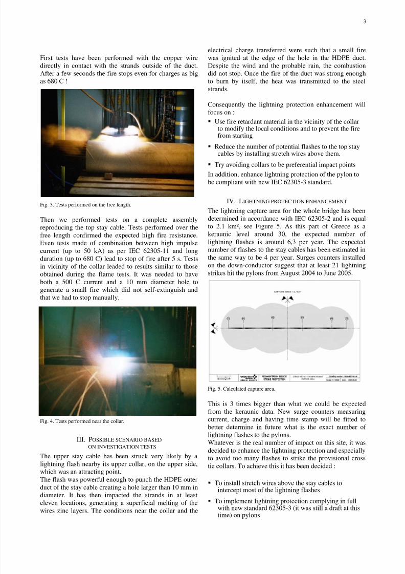
First tests have been performed with the copper wire
directly in contact with the strands outside of the duct.
After a few seconds the fire stops even for charges as big
as 680 C !
Fig. 3. Tests performed on the free length.
Then we performed tests on a complete assembly
reproducing the top stay cable. Tests performed over the
free length confirmed the expected high fire resistance.
Even tests made of combination between high impulse
current (up to 50 kA) as per IEC 62305-11 and long
duration (up to 680 C) lead to stop of fire after 5 s. Tests
in vicinity of the collar leaded to results similar to those
obtained during the flame tests. It was needed to have
both a 500 C current and a 10 mm diameter hole to
generate a small fire which did not self-extinguish and
that we had to stop manually.
Fig. 4. Tests performed near the collar.
III. POSSIBLE SCENARIO BASED ON INVESTIGATION TESTS
The upper stay cable has been struck very likely by a
lightning flash nearby its upper collar, on the upper side,which was an attracting point.
The flash was powerful enough to punch the HDPE outer
duct of the stay cable creating a hole larger than 10 mm in
diameter. It has then impacted the strands in at least
eleven locations, generating a superficial melting of thewires zinc layers. The conditions near the collar and the
electrical charge transferred were such that a small fire
was ignited at the edge of the hole in the HDPE duct.
Despite the wind and the probable rain, the combustion
did not stop. Once the fire of the duct was strong enough
to burn by itself, the heat was transmitted to the steel
strands.
Consequently the lightning protection enhancement will
focus on :
Use fire retardant material in the vicinity of the collarto modify the local conditions and to prevent the firefrom starting
Reduce the number of potential flashes to the top staycables by installing stretch wires above them.
Try avoiding collars to be preferential impact points
In addition, enhance lightning protection of the pylon to
be compliant with new IEC 62305-3 standard.
IV. LIGHTNING PROTECTION ENHANCEMENT The lightning capture area for the whole bridge has been
determined in accordance with IEC 62305-2 and is equal
to 2.1 km², see Figure 5. As this part of Greece as a
keraunic level around 30, the expected number of
lightning flashes is around 6,3 per year. The expectednumber of flashes to the stay cables has been estimated in
the same way to be 4 per year. Surges counters installed
on the down-conductor suggest that at least 21 lightning
strikes hit the pylons from August 2004 to June 2005.
Fig. 5. Calculated capture area.
This is 3 times bigger than what we could be expectedfrom the keraunic data. New surge counters measuring
current, charge and having time stamp will be fitted to
better determine in future what is the exact number of
lightning flashes to the pylons.
Whatever is the real number of impact on this site, it was
decided to enhance the lightning protection and especiallyto avoid too many flashes to strike the provisional cross
tie collars. To achieve this it has been decided :
To install stretch wires above the stay cables tointercept most of the lightning flashes
To implement lightning protection complying in fullwith new standard 62305-3 (it was still a draft at thistime) on pylons

7/31/2019 ICLP 2006 Bridge-Corrected
http://slidepdf.com/reader/full/iclp-2006-bridge-corrected 4/4
4
Fig. 6. Enhance pylon protection
A. Pylon protection enhancement
As it was likely that corner and edge of the top part of the
pylon be the preferential attachment point, a ringconductor with 4 rods at each corner have been installed.
Two additional down-conductors have been also
implemented to make a mesh as well as 3 more ringelectrodes evenly spaced from top of the pylon to the
bottom of the metallic stay cable anchorage box. Another
ring conductor has been installed at sea level to share the
current between 4 earthing systems. Equipotential
bonding of pylon metallic part has also been provided
(see Fig. 6).
B. Stay cable protection
Stainless steel high strength strands have been used to
build a stretch wire above the top stay cables, connectedto the pylon mast upper ring conductors. The stretch wire
is running parallel to the upper stay cable and is
connected at mid-span to a central piece which is attached
by hangers to the deck The tension in the stretch wire is
close to the tension in the stay cable strand so as to have
similar deflections in order to ensure a minimum distance
between stretch wires and stay cables. Safety distance has
been calculated so that even in case of strong wind and
lightning occurring at the same time the distance betweenthe stretch wire and the upper stay cable always remain
above the spark over voltage. At last redundancy ensures
that no stretch wires can fall on the deck even in case of
exceptional strike.
Fig. 7. Stretch wire and stay cables
V. CONCLUSION
Thorough study of the 27th of January 2005 event has
been made over almost one year. Long experience of stay
cable bridges over the world even in more severe areas
than Greece demonstrates what we can naturally feel.
Such a big mass of steel cannot be seriously impacted bya lightning strike. Normally no specific protection is
provided on the stay cables and only pylons are protected.
It appears that no lightning impulse current has been able
in laboratory to generate a fire. Situation was surely more
critical on the bridge as wind and rain were present. Onlya quite large long duration current has been able to create
such circumstances in laboratory and only in a very
specific configuration. The study performed has been able
to propose and validate a likely scenario. In spite of the
extremely low probability of such an event it has been
decided to enhance the existing bridge lightning
protection, consisting in reducing the number of direct
strikes on the stay cables by means of stretch wires and inpreventing the fire to start by neutralizing the local
conditions near the provisional cross tie collar.
VI. REFERENCES
IEC 62305-1, Protection against lightning part 1 general
principles, January 2006.


![ICLP—SIPDA ^ ] Detailed Program](https://img.pdfslide.us/doc/110x75/61a91ebe4c7be4568b28cc4f/iclpsipda-detailed-program.jpg)