Embed Size (px)
Citation preview
Ed Green Engineering 315 Thorn St Sewickley PA 412-208-5884
FEA Analysis of Reign Maker WSD
3/28/2021
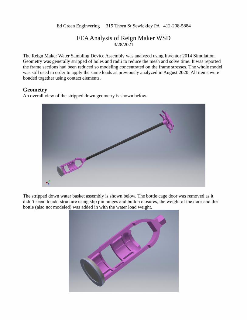
The Reign Maker Water Sampling Device Assembly was analyzed using Inventor 2014 Simulation.
Geometry was generally stripped of holes and radii to reduce the mesh and solve time. It was reported
the frame sections had been reduced so modeling concentrated on the frame stresses. The whole model
was still used in order to apply the same loads as previously analyzed in August 2020. All items were
bonded together using contact elements.
Geometry
An overall view of the stripped down geometry is shown below.
The stripped down water basket assembly is shown below. The bottle cage door was removed as it
didn’t seem to add structure using slip pin hinges and button closures, the weight of the door and the
bottle (also not modeled) was added in with the water load weight.
Ed Green Engineering 315 Thorn St Sewickley PA 412-208-5884
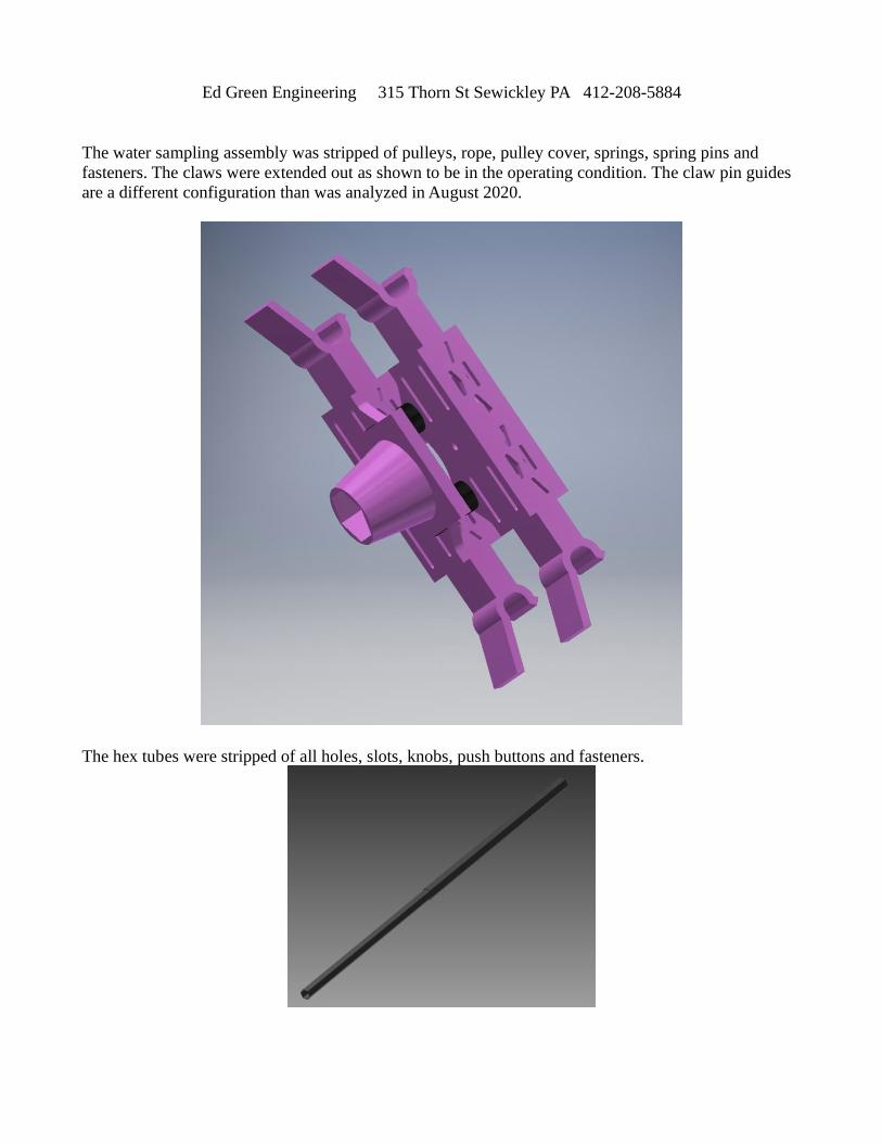
The water sampling assembly was stripped of pulleys, rope, pulley cover, springs, spring pins and
fasteners. The claws were extended out as shown to be in the operating condition. The claw pin guides
are a different configuration than was analyzed in August 2020.
The hex tubes were stripped of all holes, slots, knobs, push buttons and fasteners.
Ed Green Engineering 315 Thorn St Sewickley PA 412-208-5884
Materials
The same material properties were assigned per the August 2020 analysis
Nylon
Bottle Cage
Base Spring Plunger
Pole Adaptor
Frame Clamps
Top Frame
Mechanical Properties
Density .0408 lbmass/in^3
Yield Strength 6100 psi
Ultimate Tensile Strength 12000 psi
Young’s Modulus .288e6 psi
Poisson’s Ratio .35
Shear Modulus .1e6 psi
Stainless steel
Metal Base Plate
Mechanical Properties
Density .291 lbmass/in^3
Yield Strength 36260 psi
Ultimate Tensile Strength 78320 psi
Young’s Modulus 28e6 psi
Poisson’s Ratio .3
Shear Modulus 10.7e6 psi
ABS Plastic – this was used in place of rubber to simplify the model. The fasteners were
removed and the rubber had too much elasticity to hold the assemlby in tension.
Rubber bumper
Mechanical Properties
Density .038 lbmass/in^3
Yield Strength 2900 psi
Ultimate Tensile Strength 4293 psi
Young’s Modulus .3e6 psi
Poisson’s Ratio .38
Shear Modulus .117e6 psi
Titanium – this was used for simplification, as the carbon graphite properties are orthotropic
Carbon Fiber Hex Tube
Mechanical Properties
Density .16 lbmass/in^3
Yield Strength 39972 psi
Ultimate Tensile Strength 49965 psi
Young’s Modulus 15e6 psi
Poisson’s Ratio .36
Shear Modulus 5.4e6 psi
Ed Green Engineering 315 Thorn St Sewickley PA 412-208-5884
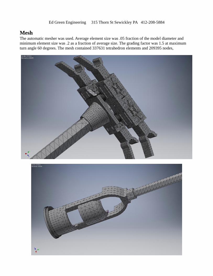
Mesh
The automatic mesher was used. Average element size was .05 fraction of the model diameter and
minimum element size was .2 as a fraction of average size. The grading factor was 1.5 at maximum
turn angle 60 degrees. The mesh contained 337631 tetrahedron elements and 209395 nodes,
Ed Green Engineering 315 Thorn St Sewickley PA 412-208-5884
Constraints
In all load cases all 4 claws were constrained with a pin constraint as if they were attached to the drone.
The pin constraints were fixed in the radial and axial directions and allowed to rotate freely.
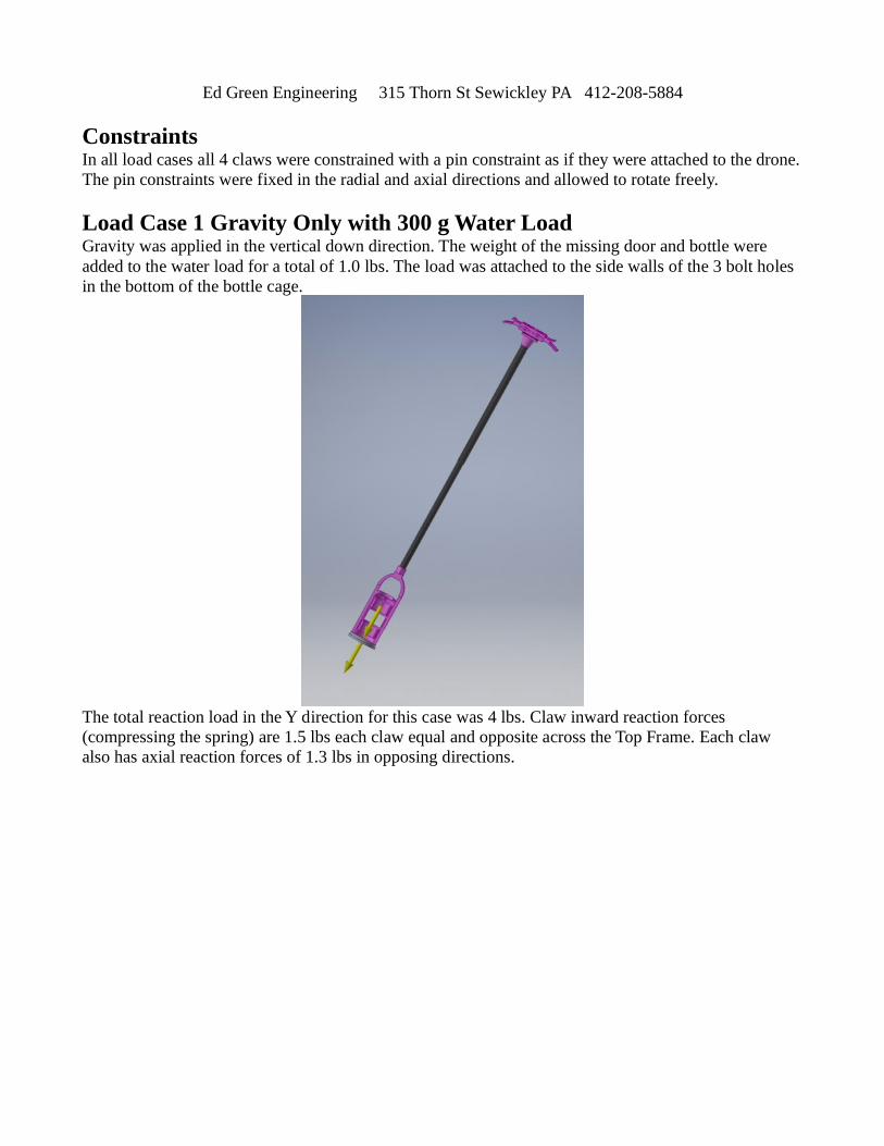
Load Case 1 Gravity Only with 300 g Water Load
Gravity was applied in the vertical down direction. The weight of the missing door and bottle were
added to the water load for a total of 1.0 lbs. The load was attached to the side walls of the 3 bolt holes
in the bottom of the bottle cage.
The total reaction load in the Y direction for this case was 4 lbs. Claw inward reaction forces
(compressing the spring) are 1.5 lbs each claw equal and opposite across the Top Frame. Each claw
also has axial reaction forces of 1.3 lbs in opposing directions.
Ed Green Engineering 315 Thorn St Sewickley PA 412-208-5884
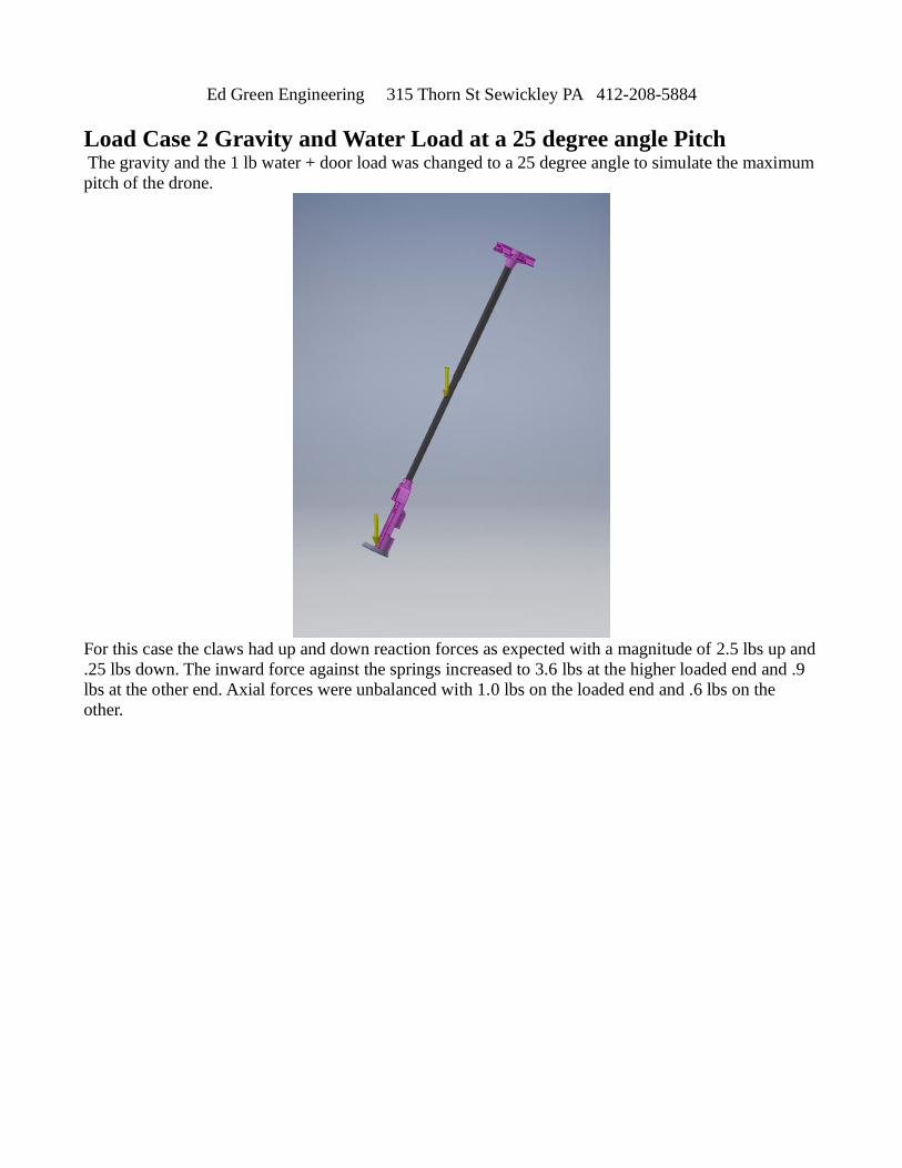
Load Case 2 Gravity and Water Load at a 25 degree angle Pitch
The gravity and the 1 lb water + door load was changed to a 25 degree angle to simulate the maximum
pitch of the drone.
For this case the claws had up and down reaction forces as expected with a magnitude of 2.5 lbs up and
.25 lbs down. The inward force against the springs increased to 3.6 lbs at the higher loaded end and .9
lbs at the other end. Axial forces were unbalanced with 1.0 lbs on the loaded end and .6 lbs on the
other.
Ed Green Engineering 315 Thorn St Sewickley PA 412-208-5884
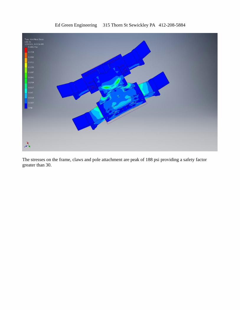
The stresses on the frame, claws and pole attachment are peak of 188 psi providing a safety factor
greater than 30.
Ed Green Engineering 315 Thorn St Sewickley PA 412-208-5884
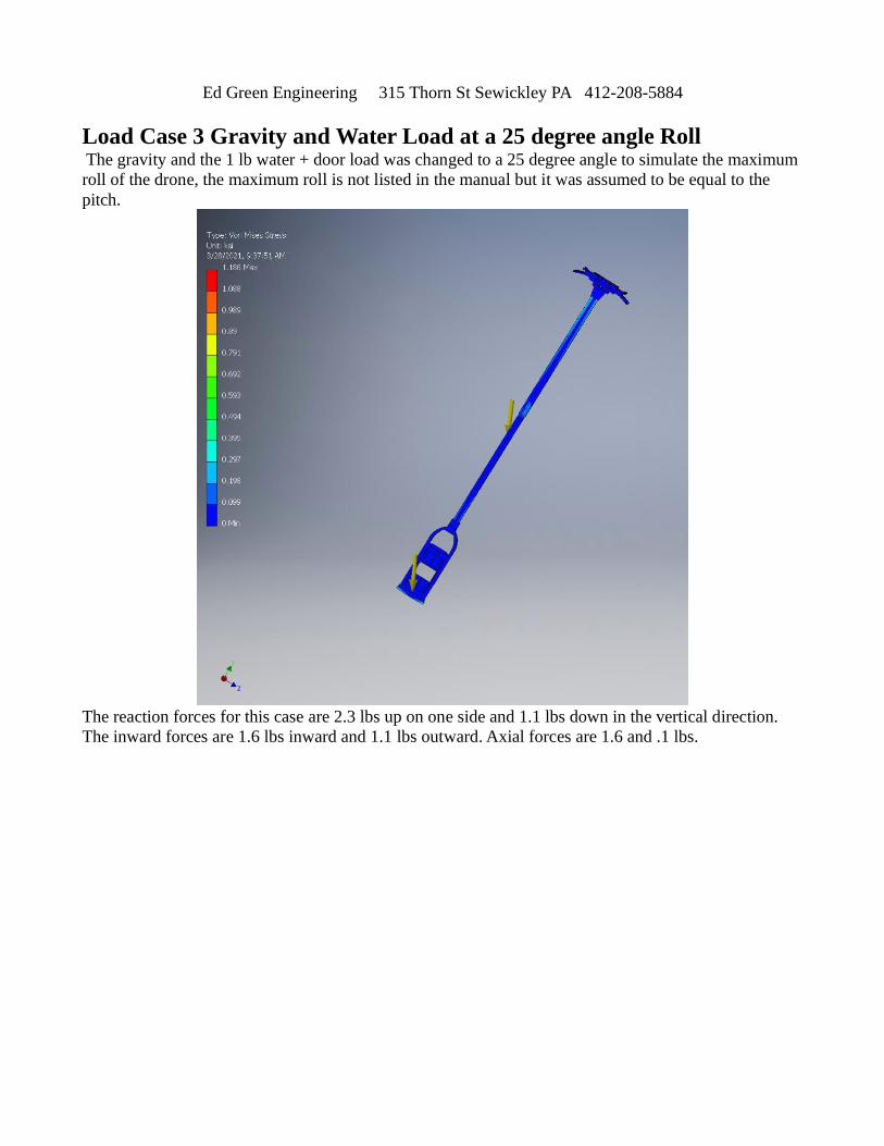
Load Case 3 Gravity and Water Load at a 25 degree angle Roll
The gravity and the 1 lb water + door load was changed to a 25 degree angle to simulate the maximum
roll of the drone, the maximum roll is not listed in the manual but it was assumed to be equal to the
pitch.
The reaction forces for this case are 2.3 lbs up on one side and 1.1 lbs down in the vertical direction.
The inward forces are 1.6 lbs inward and 1.1 lbs outward. Axial forces are 1.6 and .1 lbs.
Ed Green Engineering 315 Thorn St Sewickley PA 412-208-5884
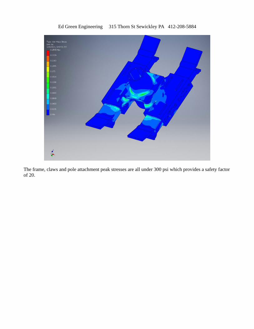
The frame, claws and pole attachment peak stresses are all under 300 psi which provides a safety factor
of 20.
Ed Green Engineering 315 Thorn St Sewickley PA 412-208-5884
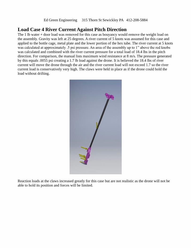
Load Case 4 River Current Against Pitch Direction
The 1 lb water + door load was removed for this case as bouyancy would remove the weight load on
the assembly. Gravity was left at 25 degrees. A river current of 5 knots was assumed for this case and
applied to the bottle cage, metal plate and the lower portion of the hex tube. The river current at 5 knots
was calculated at approximately .5 psi pressure. An area of the assembly up to 1” above the red knobs
was calculated and combined with the river current pressure for a total load of 18.4 lbs in the pitch
direction. For comparison, the manual lists maximum wind resistance at 8 m/s. The pressure generated
by this equals .0055 psi creating a 1.7 lb load against the drone. It is believed the 18.4 lbs of river
current will move the drone through the air and the river current load will not exceed 1.7 so the river
current load is conservatively very high. The claws were held in place as if the drone could hold the
load without drifting.
Reaction loads at the claws increased greatly for this case but are not realistic as the drone will not be
able to hold its position and forces will be limited.
Ed Green Engineering 315 Thorn St Sewickley PA 412-208-5884
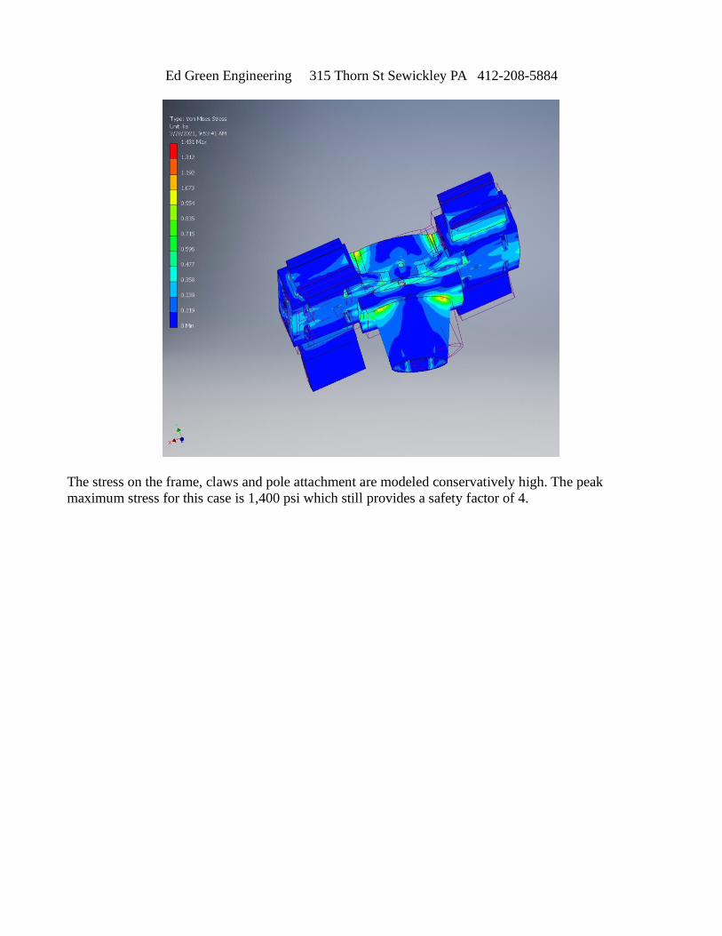
The stress on the frame, claws and pole attachment are modeled conservatively high. The peak
maximum stress for this case is 1,400 psi which still provides a safety factor of 4.
Ed Green Engineering 315 Thorn St Sewickley PA 412-208-5884
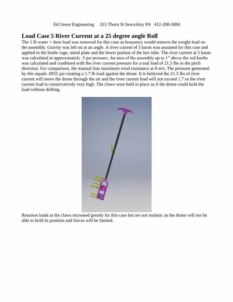
Load Case 5 River Current at a 25 degree angle Roll
The 1 lb water + door load was removed for this case as bouyancy would remove the weight load on
the assembly. Gravity was left on at an angle. A river current of 5 knots was assumed for this case and
applied to the bottle cage, metal plate and the lower portion of the hex tube. The river current at 5 knots
was calculated at approximately .5 psi pressure. An area of the assembly up to 1” above the red knobs
was calculated and combined with the river current pressure for a toal load of 21.5 lbs in the pitch
direction. For comparison, the manual lists maximum wind resistance at 8 m/s. The pressure generated
by this equals .0055 psi creating a 1.7 lb load against the drone. It is believed the 21.5 lbs of river
current will move the drone through the air and the river current load will not exceed 1.7 so the river
current load is conservatively very high. The claws were held in place as if the drone could hold the
load without drifting.
Reaction loads at the claws increased greatly for this case but are not realistic as the drone will not be
able to hold its position and forces will be limited.
Ed Green Engineering 315 Thorn St Sewickley PA 412-208-5884
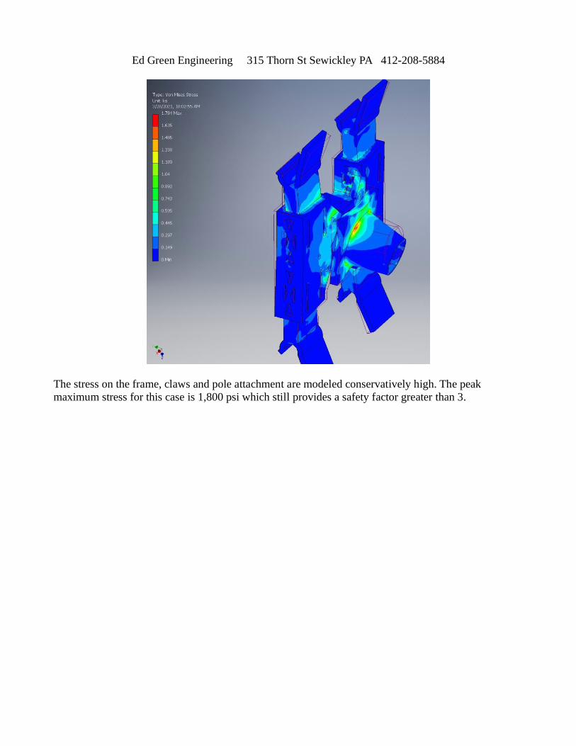
The stress on the frame, claws and pole attachment are modeled conservatively high. The peak
maximum stress for this case is 1,800 psi which still provides a safety factor greater than 3.
Ed Green Engineering 315 Thorn St Sewickley PA 412-208-5884
Results Discussion
This report was tailored to checking the stresses in the redesigned frame. Frame stresses are low and
have significant safety margin. The cases for river current forces against the drone were considered as
if the drone was held steady in one spot. This case is over conservative as the drone cannot hold against
the river current and net forces on the drone are limited below the fully held drone case. Even those
cases have a safety factor greater than 3 to yield.
The frame and claw changes that have been made to lighten them up provide adequate strength against
the expected forces.