Embed Size (px)
Citation preview

FD 260-10
Feeder for FD 260 Tabber
Operator Manual
1/2011 First Edition


3
TABLE OF CONTENTS
1. INTRODUCTION .............................................................................................. 1
1.1 FD 260-10 Description .................................................................................... 1 1.2 Items Included ................................................................................................ 2 1.3 Operating Manual Safety Terms ..................................................................... 3 1.4 Safety Precautions .......................................................................................... 4 1.5 Operating Manual Terms ................................................................................ 4 1.6 Warranty ......................................................................................................... 5 1.7 Ordering Additional Equipment ....................................................................... 6
2. SPECIFICATIONS & REQUIREMENTS .......................................................... 7
2.1 Specifications .................................................................................................. 7 2.2 Operating Requirements ................................................................................. 7
3. POWER CONNECTION ................................................................................... 8
3.1 Safety .............................................................................................................. 8 3.2 Line Voltage .................................................................................................... 8 3.3 Line Fuses .................................................................................................... 10 3.4 Power Cord ................................................................................................... 11
4. SET-UP ........................................................................................................... 12
4.1 Feed Wedge ................................................................................................. 12 4.2 Product Stop Extension ................................................................................ 13 4.3 Placing the FD 260-10 In-Line ...................................................................... 14
5. OPERATION ................................................................................................... 16
5.1 Loading Mail Pieces ...................................................................................... 16 5.2 Feeding Mail Pieces...................................................................................... 17 5.3 Adjusting Speed ............................................................................................ 18
6. MAINTENANCE .............................................................................................. 19
6.1 Cleaning ........................................................................................................ 19 6.2 Replacing A Static Brush .............................................................................. 19 6.3 Replacing A Fuse ......................................................................................... 19
7. TROUBLESHOOTING ................................................................................... 21
7.1 Troubleshooting Chart .................................................................................. 21
8. SERVICE ........................................................................................................ 22
8.1 Service .......................................................................................................... 22 8.2 Repacking Instructions.................................................................................. 22

4

1
1. INTRODUCTION
1.1 FD 260-10
Description
The FD 260-10 is an automatic feeding device used to feed mail pieces into tabbers, printers and other mail processing machines. A stack of mail pieces is loaded in the feed tray. Separators and feed rolls separate the stack into single pieces and feed the pieces into a tabber or printer.
Figure 1.1 -- The FD 260-10 Feeder in-line with the FD 260 tabber and the
optional FD 260-20 conveyor

2
1.2 Items Included
The following items are shipped together in one box. Take note of each as you unpack the box (refer to
Figure 1.2).
1. FD 260-10 Feeder 2. Feed wedge 3. Product stop extension 4. Power cord 5. Operating manual
1
5
4
3
2
Figure 1.2 -- FD 260-10 with Accessories
WARNING
THE FD 260-10 IS A HEAVY MACHINE.
USE PROPER LIFTING TECHNIQUES TO
SET IT ON A WORK SURFACE.
3
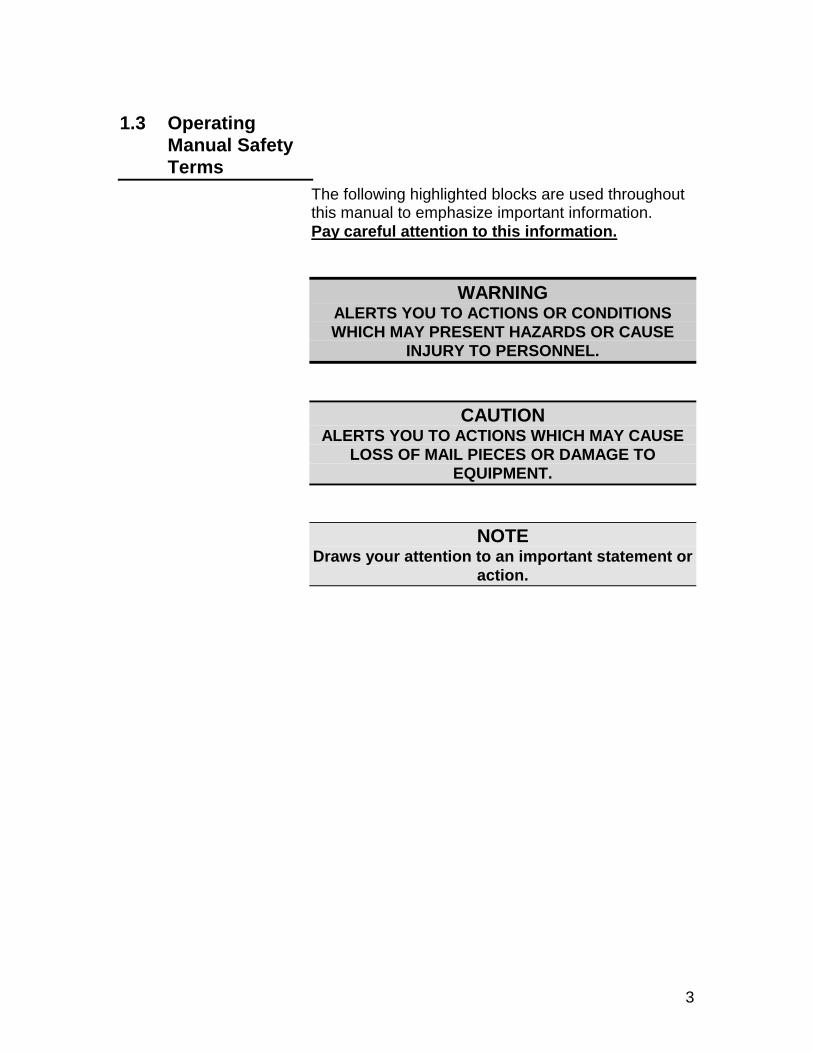
1.3 Operating
Manual Safety
Terms
The following highlighted blocks are used throughout this manual to emphasize important information.
Pay careful attention to this information.
WARNING ALERTS YOU TO ACTIONS OR CONDITIONS
WHICH MAY PRESENT HAZARDS OR CAUSE
INJURY TO PERSONNEL.
CAUTION ALERTS YOU TO ACTIONS WHICH MAY CAUSE
LOSS OF MAIL PIECES OR DAMAGE TO
EQUIPMENT.
NOTE Draws your attention to an important statement or
action.
4
1.4 Safety
Precautions
Observe the following safety precautions and warnings when operating, cleaning or repairing the FD 260-10. Failure to do so may result in physical injury or damage to the FD 260-10. The manufacturer assumes no liability for your failure to comply with these requirements.
WARNING
NEVER CLEAN, CLEAR OR DISASSEMBLE THE
FD 260-10 WITHOUT FIRST UNPLUGGING THE
POWER CORD.
WARNING
KEEP LOOSE CLOTHING, TIES, SCARVES AND
HAIR AWAY FROM ALL MOVING PARTS.
WARNING
DO NOT PLACE FINGERS OR TOOLS BETWEEN
OR NEAR MOVING PARTS.
1.5 Operating
Manual Terms
input end where mail pieces enter
output end where mail pieces exit
operator side side of the FD 260-10 where the controls are located
non-operator side side opposite the operator side
leading edge edge of mail piece that enters and exits the FD 260-10 first
trailing edge edge of mail piece that enters and exits the FD 260-10 last

5
1.6 Warranty
NOTE Your Formax FD 260-10 is covered under warranty
by the dealership from which you purchased it. If
you have any questions about the FD 260-10 or its
warranty call your authorized Formax dealer.
Formax FD 260-10 Feeder against defects in materials and workmanship for a period of six months from the original ship date when used in accordance with the operating instructions in this manual. This warranty covers the cost of parts when the machine is presented by its original purchaser to an authorized Formax Dealer. Should warranty repairs become necessary, the service provider, at his/her option, will repair or replace such parts required to restore the FD 260-10 to serviceable condition. This warranty does not cover consumable parts such as belts and rollers used to contact and transport mail pieces. This warranty does not extend to incidental or consequential damages arising out of a warranty claim, or to costs associated with maintenance of the equipment. This warranty does not cover damages resulting from shipping, accident, misuse, abuse, neglect, mishandling, alteration or modification. Your rights under this warranty may vary from state to state.

6
1.7 Ordering
Additional
Equipment
To order or find out about additional Formax equipment, contact an authorized Formax dealer.
Figure 1.3 -- Tabbing with Formax equipment.
The FD 260-10 in-line with the FD 260 Tabber & FD 260-20 Conveyor.

7
2. SPECIFICATIONS & REQUIREMENTS
2.1 Specifications
Size 23" L x 12
1/2" H x 16" W
Weight 48 lb. assembled
Power Possible line voltages are 240V, 230V, 220V, 120V, and 100V at 50-60 Hz
Production Up to 15,000 mail pieces (4" ±
1/8" long) per hour
2.2 Operating
Requirements
Mail Piece Size Length: up to 14" Width: 3.5" minimum, 18" maximum
Mail Piece Thickness Minimum: single sheet of 20 lb. bond paper Maximum:
1/4"
Mail Piece Stack Height up to 4" without product stop extension up to 8" with product stop extension

8
3. POWER CONNECTION
WARNING
BEFORE PLUGGING THE FD 260-10 INTO AN
OUTLET, CAREFULLY READ THE FOLLOWING
INFORMATION ABOUT VOLTAGES, FUSES AND
THE POWER CORD.
3.1 Safety
The FD 260-10 can connect to any power distribution system, including the European IT Power System. Because the European IT Power System does not have a grounded neutral leg, the FD 260-10 uses protective fusing in both the neutral and hot supply lines of power.
WARNING A BLOWN FUSE IN THE NEUTRAL LEG COULD
MEAN INTERIOR PARTS OF THE FD 260-10
REMAIN AT A HAZARDOUS VOLTAGE. ALWAYS
UNPLUG THE POWER CORD BEFORE REMOVING
COVERS FROM THE FD 260-10.
3.2 Line Voltage
The FD 260-10 is rated for continuous operation using a variety of supply voltages. Possible line voltages are 240V, 230V, 220V, 120V and 100V at 50 or 60 Hz. The manufacturer configures the FD 260-10 to operate with the voltage requested by the customer.
CAUTION VERIFY THE CORRECT VOLTAGE SETTING
BEFORE PLUGGING THE FD 260-10 INTO AN
OUTLET.
Read the current voltage setting through the VOLTAGE SELECTOR WINDOW on the input end of
the FD 260-10 (refer to Figure 3.1). Use the following instructions to change the voltage setting:

9
NOTE The detachable POWER CORD may have to be
changed to match the particular power-source
output.
1. Unplug the POWER CORD.
2. Use a small screwdriver or similar tool to push up on and release the FUSE DRAWER LOCKING TAB.
3. Pull the FUSE DRAWER out of the POWER ENTRY CASING.
4. Pull the VOLTAGE SELECTOR out of the POWER ENTRY CASING.
5. Rotate the VOLTAGE SELECTOR until the correct voltage is on the same side as the VOLTAGE SELECTOR WINDOW.
6. Place the VOLTAGE SELECTOR in the POWER ENTRY CASING and verify the correct voltage selection.
7. Place the FUSE DRAWER in the POWER ENTRY CASING.
POWER ENTRY
FUSE
FUSE DRAWER
APPLIANCE INLET
LOCKING TAB
CASING
VOLTAGE
SELECTOR
WINDOW
FUSE DRAWER
POWER CORD
VOLTAGE
SELECTOR
Figure 3.1 -- FD 260-10 Power Connection

10
3.3 Line Fuses
The FUSE DRAWER located on the input end
contains two LINE FUSES (refer to Figure 3.1). The neutral and hot lines of power are fused. Both LINE FUSES must be intact for the FD 260-10 to operate properly.
CAUTION VERIFY THAT THE LINE FUSE VALUE IS
CORRECT FOR THE VOLTAGE SETTING.
UNPLUG THE FD 260-10 BEFORE STARTING
THIS PROCEDURE.
Use the following instructions to verify that the LINE FUSES installed have the proper fuse value or to replace a blown fuse: 1. Unplug the POWER CORD.
2. Use a small screwdriver or similar tool to push up on and release the FUSE DRAWER LOCKING TAB.
3. Pull the FUSE DRAWER out of the POWER ENTRY CASING. The LINE FUSES are inside.
4. Determine the proper fuse value as well as the condition of the LINE FUSE. The fuse value is shown on the metal tip of the LINE FUSE. The chart below lists the selected voltage in the left column followed by the proper fuse value in the right column.
Selected Voltage Line Fuse Value 100V…………………….1.0A (250V time delay) 120V…………………….1.0A (250V time delay) 220V…………………….0.5A (250V time delay) 240V (or 230V)…………0.5A (250V time delay)
5. Replace the LINE FUSE if necessary. Both LINE
FUSES must be intact for the FD 260-10 to operate properly.
6. Install the FUSE DRAWER in the POWER ENTRY CASING.

11
3.4 Power Cord
The FD 260-10 comes with a three-wire POWER CORD. The POWER CORD grounds the FD 260-10 when connected to an approved three-contact electrical outlet.
1. Plug the POWER CORD into the APPLIANCE
INLET on the input end (refer to Figure 3.1).
2. Plug the POWER CORD into a grounded outlet.
WARNING
TO PREVENT ELECTRICAL SHOCK, ONLY PLUG
THE POWER CORD INTO A GROUNDED OUTLET.

12
4. SET-UP
CAUTION ONLY PLUG THE POWER CORD INTO AN
OUTLET AFTER READING SECTION 3 –
POWER CONNECTION.
3
2
1
Figure 4.1 -- (1) Feed Wedge, (2) Product Stop Extension, (3) Power Cord
4.1 Feed Wedge
The FEED WEDGE improves the feeding of certain types of mail pieces. To install the FEED WEDGE:
1. Unscrew the FEED WEDGE knob from the tray.
2. Align the long slot in the FEED WEDGE over one of the holes in the center of the tray, with the angled edge of the WEDGE facing the FEED ROLLS.
3. Screw the FEED WEDGE knob through the slot and into the hole.

13
4.2 Product Stop
Extension
The product stop extension allows you to stack 4 extra inches of mail (8” total) in the FEED TRAY.
PRODUCT STOP
PRODUCT STOP
EXTENSION
KNOBS
NON-OPERATOR SIDEPRODUCT GUIDE
PRODUCT GUIDEOPERATOR SIDE
PRODUCT STOP
Figure 4.2 – Product Stop Extension
To install the product stop extension:
1. Loosen both PRODUCT STOP KNOBS secured
to the top of the PRODUCT STOP (refer to Figure
4.2).
2. Slide the notches in the PRODUCT STOP EXTENSION around the screws in the PRODUCT STOP KNOBS.
3. Tighten the PRODUCT STOP KNOBS into the PRODUCT STOP. The PRODUCT STOP EXTENSION should be secured to the PRODUCT STOP and form a straight surface from the tray to the top of the PRODUCT STOP EXTENSION
(refer to Figure 4.2).
14
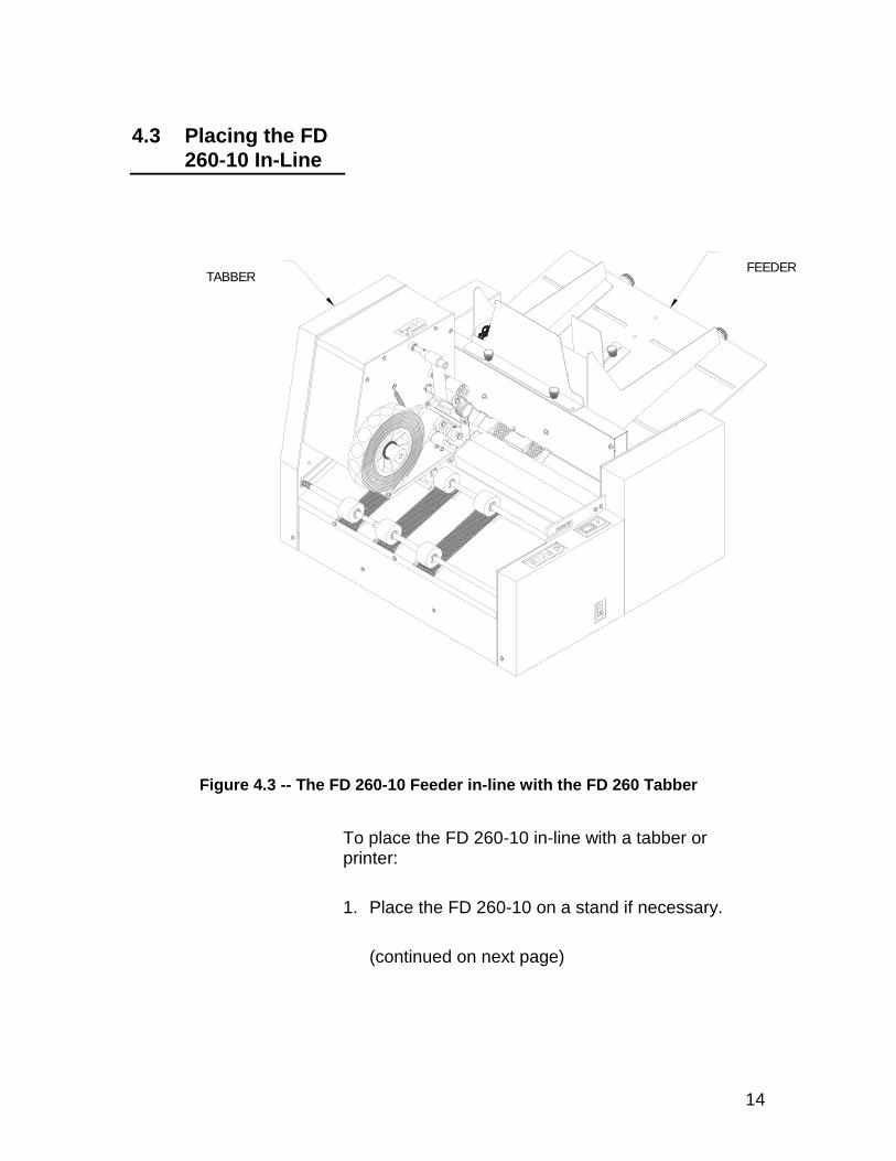
4.3 Placing the FD
260-10 In-Line
ACCUFAST FX
FEEDERACCUFAST KT
TABBER
Figure 4.3 -- The FD 260-10 Feeder in-line with the FD 260 Tabber
To place the FD 260-10 in-line with a tabber or printer:
1. Place the FD 260-10 on a stand if necessary.
(continued on next page)

15
2. Place the FD 260-10’s output end next to the tabber’s or printer’s input end, leaving a
1/8" gap to
avoid scratching paint.
3. Feed several mail pieces. If mail pieces are curled or rigid, adjust the gap using instructions in chart below:
if leading edge: then:
curls up increase the gap
curls down decrease the gap as
small as possible

16
5. OPERATION
5.1 Loading
Mail Pieces
FEED TRAY
PRODUCT GUIDE
PRODUCT GUIDE
SEPARATOR KNOBS
SEPARATORS
FEED ROLLS
PRODUCT STOP
PRODUCT WEDGE
PRODUCT WEDGE
POWER SWITCHSPEED KNOB
KNOB
KNOBSPRODUCT GUIDE
Figure 5.1 -- Operating the FD 260-10
1. Center the mail pieces with the FEED ROLLS
(refer to Figure 5.1).
2. Loosen the PAPER GUIDE KNOBS and slide the PAPER GUIDES against a sample stack of mail pieces. Tighten the knobs, making sure the mail pieces remain flat in the FEED TRAY and can slide toward the FEED ROLLS. If not, repeat this step until they do. Remove the stack.
3. Place one mail piece in the gap between the SEPARATORS and the FEED ROLLS.
4. Loosen the SEPARATOR KNOBS, then lift each one up and drop the SEPARATORS onto the mail piece.

17
5. Tighten each SEPARATOR KNOB, locking SEPARATORS in place.
NOTE Make sure both SEPARATORS are lowered and
locked to the same position to prevent mail pieces
from skewing.
6. Place a stack of mail pieces on the FEED TRAY between the PAPER GUIDES against the PAPER STOP.
7. Lift the back of the stack and slide the FEED WEDGE under the stack.
8. Lock FEED WEDGE in place.
5.2 Feeding
Mail Pieces
NOTE Turn the tabber or printer on before turning on the
FD 260-10.
1. Load mail pieces (refer to Section 5.1).
2. Turn the POWER SWITCH ON.
3. Turn the SPEED KNOB clockwise to start or accelerate feeding. If feeding does not start, turn the SPEED KNOB counterclockwise as far as it will go, then turn it clockwise.
4. Observe the feeding of the mail pieces. If they do not feed consistently and one at a time, loosen the SEPARATOR KNOBS, lift up and lower the SEPARATORS onto a single mail piece and tighten the SEPARATOR KNOBS. Repeat this step until mail pieces feed consistently, one at a time.
5. Feed several mail pieces. If mail pieces are curled or rigid, adjust the gap using instructions in chart below:
if leading edge: then:
curls up increase the gap
curls down decrease the gap as
small as possible

18
5.3 Adjusting
Speed
Once mail pieces are feeding consistently and one at a time, adjust the FD 260-10’s speed to match the speed of the in-line tabber or printer.
To adjust the speed:
turn SPEED KNOB: to:
clockwise feed faster
counterclockwise feed slower
all the way
counterclockwise
stop feeding

19
6. MAINTENANCE
6.1 Cleaning
How often the FD 260-10 needs cleaning depends on the amount of paper dust your mail pieces generate. Wipe surface dust or debris from the FD 260-10 with a damp cloth as necessary.
6.2 Replacing A
Static Brush
Inspect the static brush regularly for wear on the bristles. The static brush is located at the output end of the FD 260-10. When some bristles wear to half their original length, the static brush must be replaced. The bristles will most likely not wear evenly. Compare the worn bristles to unworn bristles (on the outside edges). Contact an authorized Formax dealer to replace your static brush.
WARNING WORN BRISTLES ON THE STATIC BRUSH MAY
CAUSE STATIC ELECTRICITY BUILD-UP WHICH
COULD SHOCK THE OPERATOR AND DAMAGE
EQUIPMENT.
6.3 Replacing A
Fuse
To replace a blown fuse (refer to Figure 6.1):
CAUTION VERIFY THAT THE LINE FUSE VALUE IS
CORRECT FOR THE VOLTAGE SETTING.
UNPLUG THE FD 260-10 BEFORE STARTING
THIS PROCEDURE.
1. Unplug the POWER CORD.
2. Use a small screwdriver or similar tool to push up on and release the FUSE DRAWER LOCKING TAB.

20
3. Pull the FUSE DRAWER out of the POWER ENTRY CASING. The LINE FUSES are inside.
4. Determine the proper fuse value as well as the condition of the LINE FUSE. The fuse value is shown on the metal tip of the LINE FUSE. The chart below lists the selected voltage in the left column followed by the proper fuse value in the right column.
Selected Voltage Line Fuse Value 100V…………………….1.0A (250V time delay)
120V…………………….1.0A (250V time delay) 220V…………………….0.5A (250V time delay) 240V (or 230V)…………0.5A (250V time delay)
5. Replace the LINE FUSE if necessary. Both LINE
FUSES must be intact for the FD 260-10 to operate properly.
6. Install the FUSE DRAWER in the POWER ENTRY CASING.
POWER ENTRY
FUSE
FUSE DRAWER
APPLIANCE INLET
LOCKING TAB
CASING
VOLTAGE
SELECTOR
WINDOW
FUSE DRAWER
POWER CORD
VOLTAGE
SELECTOR
Figure 6.1 -- FD 260-10 Power Connection

21
7. TROUBLESHOOTING
WARNING
UNPLUG THE POWER CORD BEFORE
REMOVING, ADJUSTING OR REPAIRING ANY
PARTS IN THE FD 260-10.
7.1 Troubleshooting
Chart
trouble cause solution
1. Nothing works.
POWER SWITCH is
off.
Turn POWER
SWITCH on.
POWER CORD is
damaged or not
plugged in.
Replace POWER
CORD if damaged or
plug into proper
outlet.
Outlet does not have
power present.
Check circuit source
for a blown fuse or
circuit breaker.
2. Feeding is
interrupted or
prevented.
Power entry fuse is
blown.
Replace blown line
fuse (Section 6.3).
FD 260-10 keeps
blowing fuses after you
replace them.
Contact authorized
Formax Dealer.
3. Mail piece jam. Too many mail pieces
feeding at one time.
Clear jam. Raise both
SEPARATORS and
pull the jammed mail
pieces out of FD 260-
10. Review feeding
instructions (Section
5.2).
4. Motor is running,
but no mail
pieces feed.
Gap between
SEPARATORS and
FEED ROLLS is too
small for mail pieces to
pass through the gap.
Review the feeding
instructions (Section
5.2).

22
8. SERVICE
8.1 Service
If any problems occur with this equipment or if you need assistance installing or operating your FD 260-10, contact an authorized Formax dealer.
NOTE When calling for service, have your
FD 260-10’s serial number handy.
8.2 Repacking
Instructions
If it is necessary to ship your FD 260-10 to an authorized Formax dealer for service, pack it in the original shipping container and packaging material. If the original container is not available, the FD 260-10 should be carefully packed so that it will not be damaged in transit.
NOTE If the FD 260-10 is packed correctly, your
Shipping Carrier is liable for any damages that
occur during shipping.
Use the following instructions to pack the FD 260-10 with commercially available materials. 1. Double wrap the machine in heavy plastic.
2. Use a heavy duty, double-walled container of 350-pound test material.
3. Surround the FD 260-10 on ALL sides with at least 4 to 5 inches of shock absorbing packaging material. This will provide firm cushioning and prevent movement inside the container.
4. Seal the top and bottom of the shipping container with strong tape or banding material.
5. Clearly and legibly mark the shipping container FRAGILE.
6. Contact your authorized Formax dealer.