Embed Size (px)
Citation preview
FCC ID: C3K1056
Report No.: RF941101L19 1 Report Format Version 2.0.2
FCC TEST REPORT
REPORT NO.: RF941101L19MODEL NO.: 1056RECEIVED: Nov. 01, 2005
TESTED: Nov. 10, 2005ISSUED: Nov. 11, 2005
APPLICANT : Microsoft CorporationADDRESS : One Microsoft Way, Redmond, WA 98052-6399,
U.S.A.
ISSUED BY : Advance Data Technology CorporationLAB ADDRESS : No. 47, 14th Ling, Chia Pau Tsuen, Lin Kou Hsiang
244, Taipei Hsien, Taiwan, R.O.C.TEST LOCATION : No. 19, Hwa Ya 2nd Rd., Wen Hwa Tsuen, Kwei
Shan Hsiang, Taoyuan Hsien 333, Taiwan, R.O.C.
This test report consists of 23 pages in total. It may be duplicated completely for legal usewith the approval of the applicant. It should not be reproduced except in full, without thewritten approval of our laboratory. The client should not use it to claim product endorsementby CNLA, A2LA or any government agencies. The test results in the report only apply to thetested sample.
0528ILAC MRANo. 2177-01

FCC ID: C3K1056
Report No.: RF941101L19 2 Report Format Version 2.0.2
Table of Contents1 CERTIFICATION............................................................................................. 3
2 SUMMARY OF TEST RESULTS..................................................................... 4
2.1 MEASUREMENT UNCERTAINTY .................................................................. 4
3 GENERAL INFORMATION ............................................................................. 5
3.1 GENERAL DESCRIPTION OF EUT................................................................ 53.2 DESCRIPTION OF TEST MODES.................................................................. 73.2.1 CONFIGURATION OF SYSTEM UNDER TEST............................................. 73.2.2 TEST MODE APPLICABILITY AND TESTED CHANNEL DETAIL .................. 83.3 GENERAL DESCRIPTION OF APPLIED STANDARDS ................................. 83.4 DESCRIPTION OF SUPPORT UNITS............................................................ 8
4 TEST PROCEDURE AND RESULT ................................................................ 9
4.1 CONDUCTED EMISSION MEASUREMENT .................................................. 94.2 RADIATED EMISSION MEASUREMENT ....................................................... 94.2.1 LIMITS OF RADIATED EMISSION MEASUREMENT..................................... 94.2.2 TEST INSTRUMENT..................................................................................... 104.2.3 TEST PROCEDURE ......................................................................................114.2.4 DEVIATION FROM TEST STANDARD ..........................................................114.2.5 TEST SETUP ................................................................................................ 124.2.6 EUT OPERATING CONDITION .................................................................... 124.2.7 TEST RESULTS............................................................................................ 134 INFORMATION ON THE TESTING LABORATORIES.................................. 22
APPENDIX-A ...........................................................................................................A-1

FCC ID: C3K1056
Report No.: RF941101L19 3 Report Format Version 2.0.2
1 CERTIFICATION
PRODUCT : Microsoft® Wireless Notebook Optical Mouse 3000BRAND NAME : Microsoft®
MODEL NO. : 1056APPLICANT : Microsoft Corporation
TESTED : Nov. 10, 2005TEST SAMPLE : ENGINEERING SAMPLE
STANDARDS : FCC Part 15, Subpart C (Section 15.227)Canada RSS-310, 2005, Issue 1ANSI C63.4:2003
The above equipment (model: 1056) has been tested by Advance Data TechnologyCorporation, and found compliance with the requirement of the above standards.The test record, data evaluation & Equipment Under Test (EUT) configurationsrepresented herein are true and accurate accounts of the measurements of thesample’s EMC characteristics under the conditions specified in this report.
PREPARED BY : , DATE : Nov. 11, 2005( Suntee Liu )
TECHNICALACCEPTANCE : , DATE : Nov. 11, 2005
Responsible for RF ( Gary Chang )
APPROVED BY : , DATE : Nov. 11, 2005( Cody Chang, Deputy Manager )

FCC ID: C3K1056
Report No.: RF941101L19 4 Report Format Version 2.0.2
2 SUMMARY OF TEST RESULTS
The EUT has been tested according to the following specifications:
APPLIED STANDARD: FCC Part 15, Subpart CSTANDARD
PARAGRAPH TEST TYPE RESULT REMARK
15.207 Conducted Emission Test NA Power supply is 1.5Vdc frombattery
15.22715.209 Radiated Emission Test PASS Minimum passing margin is
-6.60dB at 39.72MHz
2.1 MEASUREMENT UNCERTAINTY
Where relevant, the following measurement uncertainty levels have been estimatedfor tests performed on the EUT as specified in CISPR 16-4:
Measurement Frequency Uncertainty30MHz ~ 200MHz (Horizontal) 3.52 dB
30MHz ~ 200MHz (Vertical) 3.71 dB200MHz ~1000MHz (Horizontal) 3.72 dBRadiated emissions
200MHz ~1000MHz (Vertical) 3.72 dB
This uncertainty represents an expanded uncertainty expressed at approximately the95% confidence level using a coverage factor of k=2.

FCC ID: C3K1056
Report No.: RF941101L19 5 Report Format Version 2.0.2
3 GENERAL INFORMATION
3.1 GENERAL DESCRIPTION OF EUT
PRODUCT Microsoft® Wireless Notebook Optical Mouse 3000MODEL NO. 1056POWER SUPPLY 1.5Vdc from batteryMODULATION TYPE FSKCARRIER FREQUENCYOF EACH CHANNEL 27.045, 27.145 MHz
NUMBER OF CHANNEL 2ANTENNA TYPE Loop antennaDATA CABLE NAI/O PORTS NA
NOTE:1. The EUT is a wireless mouse.2. Billow Configuration Information:Configuration #: Comments: EV phase Mouse unit for formal report
Manufacturer Componenttype Part no. Revision
no. Description BOM(if known)
Microsoft Mouse Model: 1056
ST Optical Sensor 11300398000 A CHIP IC AviatorASIC TQFP-32L 11300398000
ST Microcontroller 11300398000 A CHIP IC AviatorASIC TQFP-32L 11300398000
Microsoft firmwareLucerne_0_35_11_cb06_2CH800DPI.r
am
Ta Chien PCB 10230040200 A SPCB,H-ROLLERTX,AVIAT,S2L 10230040200
KYE PCB Assy 20000041201 C PCBA,LUCERNE,TX,MS,27M 20000041201
Case toolingSKIRT 15100057201 15100057201
NYPRO Topcase KEY
TOP 15130077201 B 15130077201
DG HEI Bottom 15120560201 T1 15120560201

FCC ID: C3K1056
Report No.: RF941101L19 6 Report Format Version 2.0.2
Configuration #: Comments: DV phase Receiver unit with EMC fixes for formalreport
Manufacturer Componenttype Part no. Revision
no. Description BOM(if known)
Microsoft Receiver Model: 1051Sunplus Microcontroller 11300605200 CHIPIC,SPCP18A 11300605200
TI 11300606200 CHIPIC,TRF7904,QFN 20 11300606200
Microsoft firmware V7
Express PCB 10230436200 8 RS,SPCB,H-ROLLER RX 10230436200
KYE PCB Assy. 20000670201 PCBA,HIGHROLLER,RX 20000670201
Case tooling
Merrich Receiver TopCase 15102048201 01 Receiver Top Case 15102048201
Merrich ReceiverBottom Case 15120485201 01 Receiver Bottom
Case 15120485201
Merrich ReceiverConnect Button 15130573201 01 Receiver Connect
Button 15130573201
Host System Used for EV Testing Comments: Includes all Host and peripheral equipment inthe setup.
Manufacturer Equipment Type Part no. Serial No. Description
DELL NOTEBOOKCOMPUTER PP05L 24729091408
EPSON Printer 1 LQ-300+ DCGY017089Printer 2
3. The above EUT information was declared by manufacturer and for more detailed featuresdescription, please refer to the manufacturer's specifications or User's Manual.

FCC ID: C3K1056
Report No.: RF941101L19 7 Report Format Version 2.0.2
3.2 DESCRIPTION OF TEST MODES
2 channels provided to the EUT.Channel Frequency (MHz)
0 27.0451 27.145
3 sets of identical samples are tested and presented in the report as below.
Test Results MouseSerial Number Frequency (MHz)
A BT-PEV-19 27.045B BT-PEV-41 27.045C BT-PEV-48 27.145
3.2.1 CONFIGURATION OF SYSTEM UNDER TEST
EUT
*Test table
(Power from battery)
FAN (for control Tx use)

FCC ID: C3K1056
Report No.: RF941101L19 8 Report Format Version 2.0.2
3.2.2 TEST MODE APPLICABILITY AND TESTED CHANNEL DETAIL
Applicable toEUT ConfigureMode PLC RE<1G
Description
1 Note v BT-PEV-19, [email protected] Note v BT-PEV-19, [email protected] Note v BT-PEV-41, [email protected] Note v BT-PEV-41, [email protected] Note v BT-PEV-48, [email protected] Note v BT-PEV-48, [email protected]
Where PLC: Power Line Conducted Emission RE<1G RE: Radiated Emission below 1GHzNote: No need to concern of Conducted Emission due to the EUT is powered by battery.
Radiated Emission Test (Below 1 GHz):Following channel(s) was (were) selected for the final test as listed below.EUT Configure
ModeAvailableChannel
TestedChannel
ModulationType
1 0, 1 0 FSK2 0, 1 1 FSK3 0, 1 0 FSK4 0, 1 1 FSK5 0, 1 0 FSK6 0, 1 1 FSK
3.3 GENERAL DESCRIPTION OF APPLIED STANDARDS
The EUT is a Microsoft® Wireless Notebook Optical Mouse 3000. According to thespecifications of the manufacturer, it must comply with the requirements of thefollowing standards:
FCC Part 15, Subpart C (15.227)ANSI C63.4:2003
All test items have been performed and recorded as per the above standards.
3.4 DESCRIPTION OF SUPPORT UNITS
NA

FCC ID: C3K1056
Report No.: RF941101L19 9 Report Format Version 2.0.2
4 TEST PROCEDURE AND RESULT
4.1 CONDUCTED EMISSION MEASUREMENT
NA
4.2 RADIATED EMISSION MEASUREMENT
4.2.1 LIMITS OF RADIATED EMISSION MEASUREMENT
According to 15.227 the field strength of Emissions from intentional radiators operatedunder these frequencies bands shall not exceed the following:
Fundamental Frequency(MHz)
Field Strength of Fundamental (dBuV/m)
Peak Average26.96-27.28
100 80
Field strength limits are at the distance of 3 meters, Emissions radiated outside of thespecified bands, shall be according to the general radiated limits in 15.209 asfollowing:
Frequencies(MHz)
Field strength(microvolts/meter)
Measurement distance(meters)
0.009-0.490 2400/F(kHz) 300
0.490-1.705 24000/F(kHz) 30
1.705-30.0 30 30
30-88 100 3
88-216 150 3
216-960 200 3
Above 960 500 3
As shown in 15.35(b), for frequencies above 1000MHz, the field strength limits arebased on average detector, however, the peak field strength of any emission shall notexceed the maximum permitted average limits, specified above by more than 20dBunder any condition of modulation.
FCC ID: C3K1056
Report No.: RF941101L19 10 Report Format Version 2.0.2
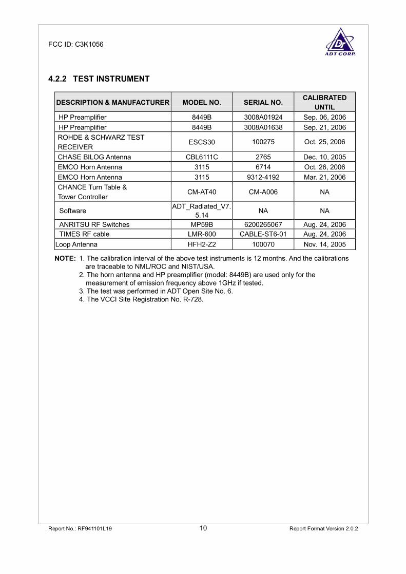
4.2.2 TEST INSTRUMENT
DESCRIPTION & MANUFACTURER MODEL NO. SERIAL NO. CALIBRATEDUNTIL
HP Preamplifier 8449B 3008A01924 Sep. 06, 2006HP Preamplifier 8449B 3008A01638 Sep. 21, 2006ROHDE & SCHWARZ TESTRECEIVER
ESCS30 100275 Oct. 25, 2006
CHASE BILOG Antenna CBL6111C 2765 Dec. 10, 2005EMCO Horn Antenna 3115 6714 Oct. 26, 2006EMCO Horn Antenna 3115 9312-4192 Mar. 21, 2006CHANCE Turn Table &Tower Controller
CM-AT40 CM-A006 NA
Software ADT_Radiated_V7.5.14 NA NA
ANRITSU RF Switches MP59B 6200265067 Aug. 24, 2006TIMES RF cable LMR-600 CABLE-ST6-01 Aug. 24, 2006
Loop Antenna HFH2-Z2 100070 Nov. 14, 2005
NOTE: 1. The calibration interval of the above test instruments is 12 months. And the calibrationsare traceable to NML/ROC and NIST/USA.
2. The horn antenna and HP preamplifier (model: 8449B) are used only for the measurement of emission frequency above 1GHz if tested.3. The test was performed in ADT Open Site No. 6.4. The VCCI Site Registration No. R-728.

FCC ID: C3K1056
Report No.: RF941101L19 11 Report Format Version 2.0.2
4.2.3 TEST PROCEDURE
a. The EUT was placed on the top of a rotating table 0.8 meters above the ground ata 3 meters semi-anechoic chamber. The table was rotated 360 degrees todetermine the position of the highest radiation.
b. The EUT was set 3 meters away from the interference-receiving antenna, whichwas mounted on the top of a variable-height antenna tower.
c. The antenna is a broadband antenna, and its height is varied from one meter tofour meters above the ground to determine the maximum value of the fieldstrength. Both horizontal and vertical polarizations of the antenna are set to makethe measurement.
d. For each suspected emission, the EUT was arranged to its worst case and thenthe antenna was tuned to heights from 1 meter to 4 meters and the rotatable tablewas turned from 0 degrees to 360 degrees to find the maximum reading.
e. The test-receiver system was set to Peak Detect Function and SpecifiedBandwidth with Maximum Hold Mode.
f. If the emission level of the EUT in peak mode was lower than the limit specified,then testing could be stopped and the peak values of the EUT would be reported.Otherwise the emissions would be re-tested one by one using peak, quasi-peakmethod or average method as specified and then reported in data sheet.
NOTE: The resolution bandwidth and video bandwidth of test receiver/spectrum analyzer is 120kHz forPeak detection (PK) and Quasi-peak detection (QP) at frequency below 1GHz.
4.2.4 DEVIATION FROM TEST STANDARD
No deviation

FCC ID: C3K1056
Report No.: RF941101L19 12 Report Format Version 2.0.2
4.2.5 TEST SETUP
4.2.6 EUT OPERATING CONDITION
Set the transmitter part of EUT under transmission condition continuously at specificchannel frequency.

FCC ID: C3K1056
Report No.: RF941101L19 13 Report Format Version 2.0.2
4.2.7 TEST RESULTS
EUTMicrosoft® WirelessNotebook Optical Mouse3000
MODEL 1056
INPUT POWER 1.5Vdc FREQUENCYRANGE Below 1000 MHz
ENVIRONMENTALCONDITIONS
27 deg. C, 74% RH,989 hPa
DETECTORFUNCTION Peak / Average
TEST MODE 1 TESTED BY Jamison Chan
TEST DISTANCE: 3 M
No.Freq.(MHz)
EmissionLevel
(dBuV/m)
Limit(dBuV/m)
Margin(dB)
AntennaHeight
(m)
TableAngle
(Degree)
RawValue
(dBuV)
CorrectionFactor(dB/m)
1 *27.045 44.23 PK 100.00 -55.77 2.14 348 36.83 7.402 *27.045 38.29 AV 80.00 -41.71 2.14 348 30.89 7.40
REMARKS: 1. Emission level(dBuV/m)=Raw Value(dBuV) + Correction Factor(dB/m)2. Correction Factor(dB/m) = Antenna Factor (dB/m) + Cable Factor (dB)3. The other emission levels were very low against the limit.4. Margin value = Emission level – Limit value.5. ”∗”= Fundamental frequency.6. Loop Antenna was used for all frequency below 30MHz.

FCC ID: C3K1056
Report No.: RF941101L19 14 Report Format Version 2.0.2
EUTMicrosoft® WirelessNotebook Optical Mouse3000
MODEL 1056
INPUT POWER 1.5Vdc FREQUENCYRANGE Below 1000 MHz
ENVIRONMENTALCONDITIONS
27 deg. C, 74% RH,989 hPa
DETECTORFUNCTION Peak / Average
TEST MODE 2 TESTED BY Jamison Chan
TEST DISTANCE: 3 M
No.Freq.(MHz)
EmissionLevel
(dBuV/m)
Limit(dBuV/m)
Margin(dB)
AntennaHeight
(m)
TableAngle
(Degree)
RawValue
(dBuV)
CorrectionFactor(dB/m)
1 *27.145 41.44 PK 100.00 -58.56 2.32 336 34.04 7.402 *27.145 37.31 AV 80.00 -42.69 2.32 336 29.91 7.40
REMARKS: 1. Emission level(dBuV/m)=Raw Value(dBuV) + Correction Factor(dB/m)2. Correction Factor(dB/m) = Antenna Factor (dB/m) + Cable Factor (dB)3. The other emission levels were very low against the limit.4. Margin value = Emission level – Limit value.5. ”∗”= Fundamental frequency.6. Loop Antenna was used for all frequency below 30MHz.

FCC ID: C3K1056
Report No.: RF941101L19 15 Report Format Version 2.0.2
EUTMicrosoft® WirelessNotebook Optical Mouse3000
MODEL 1056
INPUT POWER 1.5Vdc FREQUENCYRANGE Below 1000 MHz
ENVIRONMENTALCONDITIONS
27 deg. C, 74% RH,989 hPa
DETECTORFUNCTION Quasi-Peak
TEST MODE 1 TESTED BY Jamison Chan
ANTENNA POLARITY & TEST DISTANCE: HORIZONTAL AT 3 M
No.Freq.(MHz)
EmissionLevel
(dBuV/m)
Limit(dBuV/m)
Margin(dB)
AntennaHeight
(m)
TableAngle
(Degree)
RawValue
(dBuV)
CorrectionFactor(dB/m)
1 292.42 29.60 QP 46.00 -16.40 1.01 H 130 14.72 14.892 366.29 28.58 QP 46.00 -17.42 1.15 H 100 12.16 16.423 399.34 29.43 QP 46.00 -16.57 1.73 H 328 12.05 17.384 640.38 26.03 QP 46.00 -19.97 1.56 H 64 3.34 22.685 828.94 27.73 QP 46.00 -18.27 1.08 H 343 2.04 25.696 959.18 27.65 QP 46.00 -18.35 1.24 H 292 0.40 27.25
ANTENNA POLARITY & TEST DISTANCE: VERTICAL AT 3 M
No.Freq.(MHz)
EmissionLevel
(dBuV/m)
Limit(dBuV/m)
Margin(dB)
AntennaHeight
(m)
TableAngle
(Degree)
RawValue
(dBuV)
CorrectionFactor(dB/m)
1 43.61 27.72 QP 40.00 -12.28 1.98 V 19 14.04 13.672 399.34 26.49 QP 46.00 -19.51 1.38 V 199 9.11 17.383 842.55 26.22 QP 46.00 -19.78 2.59 V 346 0.11 26.114 879.48 26.30 QP 46.00 -19.70 3.19 V 352 0.16 26.155 916.41 27.41 QP 46.00 -18.59 2.37 V 10 0.99 26.426 949.46 27.26 QP 46.00 -18.74 2.21 V 16 0.01 27.25
REMARKS: 1. Emission level(dBuV/m)=Raw Value(dBuV) + Correction Factor(dB/m) 2. Correction Factor(dB/m) = Antenna Factor (dB/m) + Cable Factor (dB)
3. The other emission levels were very low against the limit.4. Margin value = Emission level – Limit value.

FCC ID: C3K1056
Report No.: RF941101L19 16 Report Format Version 2.0.2
EUTMicrosoft® WirelessNotebook Optical Mouse3000
MODEL 1056
INPUT POWER 1.5Vdc FREQUENCYRANGE Below 1000 MHz
ENVIRONMENTALCONDITIONS
27 deg. C, 74% RH,989 hPa
DETECTORFUNCTION Peak / Average
TEST MODE 3 TESTED BY Jamison Chan
TEST DISTANCE: 3 M
No.Freq.(MHz)
EmissionLevel
(dBuV/m)
Limit(dBuV/m)
Margin(dB)
AntennaHeight
(m)
TableAngle
(Degree)
RawValue
(dBuV)
CorrectionFactor(dB/m)
1 *27.045 45.44 PK 100.00 -54.56 2.50 0 38.04 7.402 *27.045 39.99 AV 80.00 -40.01 2.50 0 32.59 7.40
REMARKS: 1. Emission level(dBuV/m)=Raw Value(dBuV) + Correction Factor(dB/m)2. Correction Factor(dB/m) = Antenna Factor (dB/m) + Cable Factor (dB)3. The other emission levels were very low against the limit.4. Margin value = Emission level – Limit value.5. ”∗”= Fundamental frequency.6. Loop Antenna was used for all frequency below 30MHz.

FCC ID: C3K1056
Report No.: RF941101L19 17 Report Format Version 2.0.2
EUTMicrosoft® WirelessNotebook Optical Mouse3000
MODEL 1056
INPUT POWER 1.5Vdc FREQUENCYRANGE Below 1000 MHz
ENVIRONMENTALCONDITIONS
26 deg. C, 64% RH,989 hPa
DETECTORFUNCTION Peak / Average
TEST MODE 4 TESTED BY Jamison Chan
TEST DISTANCE: 3 M
No.Freq.(MHz)
EmissionLevel
(dBuV/m)
Limit(dBuV/m)
Margin(dB)
AntennaHeight
(m)
TableAngle
(Degree)
RawValue
(dBuV)
CorrectionFactor(dB/m)
1 *27.145 36.95 PK 100.00 -55.65 2.34 8 36.95 7.402 *27.145 32.03 AV 80.00 -40.57 2.34 8 32.03 7.40
REMARKS: 1. Emission level(dBuV/m)=Raw Value(dBuV) + Correction Factor(dB/m)2. Correction Factor(dB/m) = Antenna Factor (dB/m) + Cable Factor (dB)3. The other emission levels were very low against the limit.4. Margin value = Emission level – Limit value.5. ”∗”= Fundamental frequency.6. Loop Antenna was used for all frequency below 30MHz.

FCC ID: C3K1056
Report No.: RF941101L19 18 Report Format Version 2.0.2
EUTMicrosoft® WirelessNotebook Optical Mouse3000
MODEL 1056
INPUT POWER 1.5Vdc FREQUENCYRANGE Below 1000 MHz
ENVIRONMENTALCONDITIONS
27 deg. C, 74% RH,989 hPa
DETECTORFUNCTION Quasi-Peak
TEST MODE 3 TESTED BY Jamison Chan
ANTENNA POLARITY & TEST DISTANCE: HORIZONTAL AT 3 M
No.Freq.(MHz)
EmissionLevel
(dBuV/m)
Limit(dBuV/m)
Margin(dB)
AntennaHeight
(m)
TableAngle
(Degree)
RawValue
(dBuV)
CorrectionFactor(dB/m)
1 185.51 24.81 QP 43.50 -18.69 1.32 H 163 13.41 11.402 292.42 28.56 QP 46.00 -17.44 1.08 H 142 13.67 14.893 339.08 27.66 QP 46.00 -18.34 1.36 H 151 11.86 15.804 374.07 31.28 QP 46.00 -14.72 1.00 H 94 14.63 16.655 838.66 26.82 QP 46.00 -19.18 2.84 H 175 0.83 25.996 955.29 27.42 QP 46.00 -18.58 2.56 H 196 0.16 27.25
ANTENNA POLARITY & TEST DISTANCE: VERTICAL AT 3 M
No.Freq.(MHz)
EmissionLevel
(dBuV/m)
Limit(dBuV/m)
Margin(dB)
AntennaHeight
(m)
TableAngle
(Degree)
RawValue
(dBuV)
CorrectionFactor(dB/m)
1 39.72 33.40 QP 40.00 -6.60 1.50 V 253 19.84 13.552 374.07 24.06 QP 46.00 -21.94 1.50 V 289 7.41 16.653 813.39 25.21 QP 46.00 -20.79 2.39 V 202 0.01 25.204 852.26 27.14 QP 46.00 -18.86 2.11 V 181 0.81 26.335 910.58 26.36 QP 46.00 -19.64 1.64 V 274 0.08 26.276 951.40 27.53 QP 46.00 -18.47 3.13 V 121 0.27 27.26
REMARKS: 1. Emission level(dBuV/m)=Raw Value(dBuV) + Correction Factor(dB/m) 2. Correction Factor(dB/m) = Antenna Factor (dB/m) + Cable Factor (dB)
3. The other emission levels were very low against the limit.4. Margin value = Emission level – Limit value.
FCC ID: C3K1056
Report No.: RF941101L19 19 Report Format Version 2.0.2
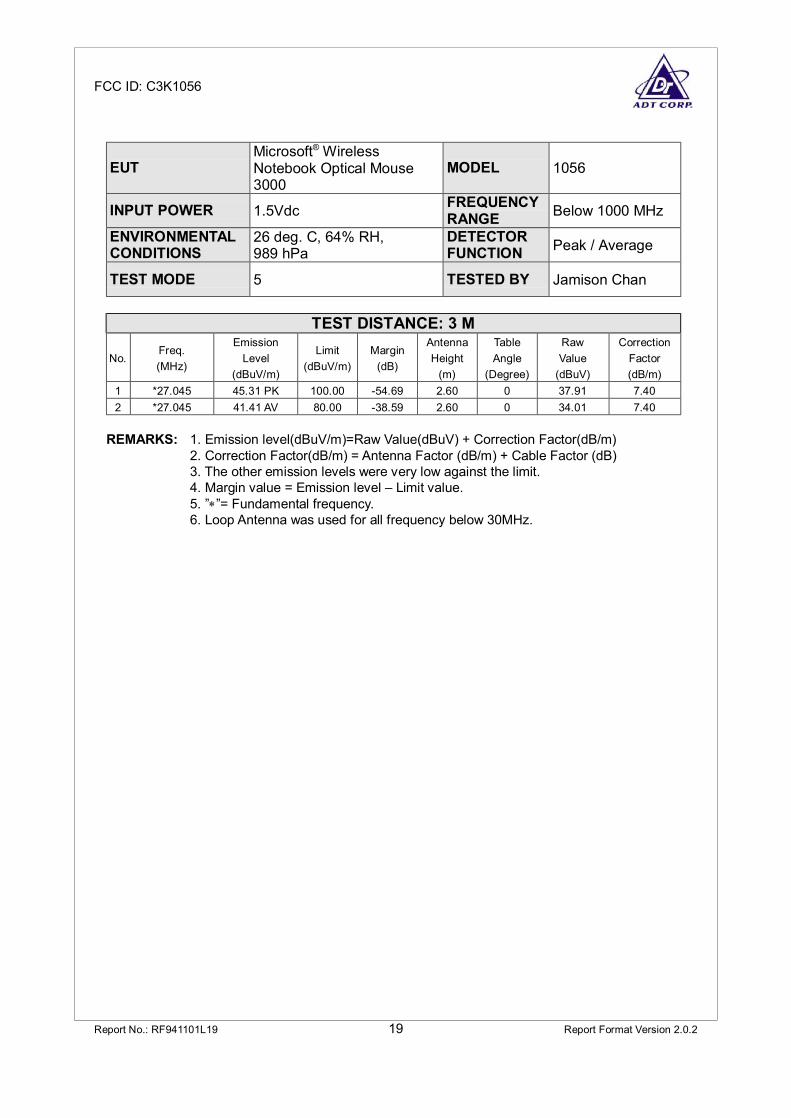
EUTMicrosoft® WirelessNotebook Optical Mouse3000
MODEL 1056
INPUT POWER 1.5Vdc FREQUENCYRANGE Below 1000 MHz
ENVIRONMENTALCONDITIONS
26 deg. C, 64% RH,989 hPa
DETECTORFUNCTION Peak / Average
TEST MODE 5 TESTED BY Jamison Chan
TEST DISTANCE: 3 M
No.Freq.(MHz)
EmissionLevel
(dBuV/m)
Limit(dBuV/m)
Margin(dB)
AntennaHeight
(m)
TableAngle
(Degree)
RawValue
(dBuV)
CorrectionFactor(dB/m)
1 *27.045 45.31 PK 100.00 -54.69 2.60 0 37.91 7.402 *27.045 41.41 AV 80.00 -38.59 2.60 0 34.01 7.40
REMARKS: 1. Emission level(dBuV/m)=Raw Value(dBuV) + Correction Factor(dB/m)2. Correction Factor(dB/m) = Antenna Factor (dB/m) + Cable Factor (dB)3. The other emission levels were very low against the limit.4. Margin value = Emission level – Limit value.5. ”∗”= Fundamental frequency.6. Loop Antenna was used for all frequency below 30MHz.

FCC ID: C3K1056
Report No.: RF941101L19 20 Report Format Version 2.0.2
EUTMicrosoft® WirelessNotebook Optical Mouse3000
MODEL 1056
INPUT POWER 1.5Vdc FREQUENCYRANGE Below 1000 MHz
ENVIRONMENTALCONDITIONS
26 deg. C, 64% RH,989 hPa
DETECTORFUNCTION Peak / Average
TEST MODE 6 TESTED BY Jamison Chan
TEST DISTANCE: 3 M
No.Freq.(MHz)
EmissionLevel
(dBuV/m)
Limit(dBuV/m)
Margin(dB)
AntennaHeight
(m)
TableAngle
(Degree)
RawValue
(dBuV)
CorrectionFactor(dB/m)
1 *27.145 36.70 PK 100.00 -35.90 2.69 0 36.70 7.402 *27.145 32.05 AV 80.00 -40.55 2.69 0 32.05 7.40
REMARKS: 1. Emission level(dBuV/m)=Raw Value(dBuV) + Correction Factor(dB/m)2. Correction Factor(dB/m) = Antenna Factor (dB/m) + Cable Factor (dB)3. The other emission levels were very low against the limit.4. Margin value = Emission level – Limit value.5. ”∗”= Fundamental frequency.6. Loop Antenna was used for all frequency below 30MHz.
FCC ID: C3K1056
Report No.: RF941101L19 21 Report Format Version 2.0.2
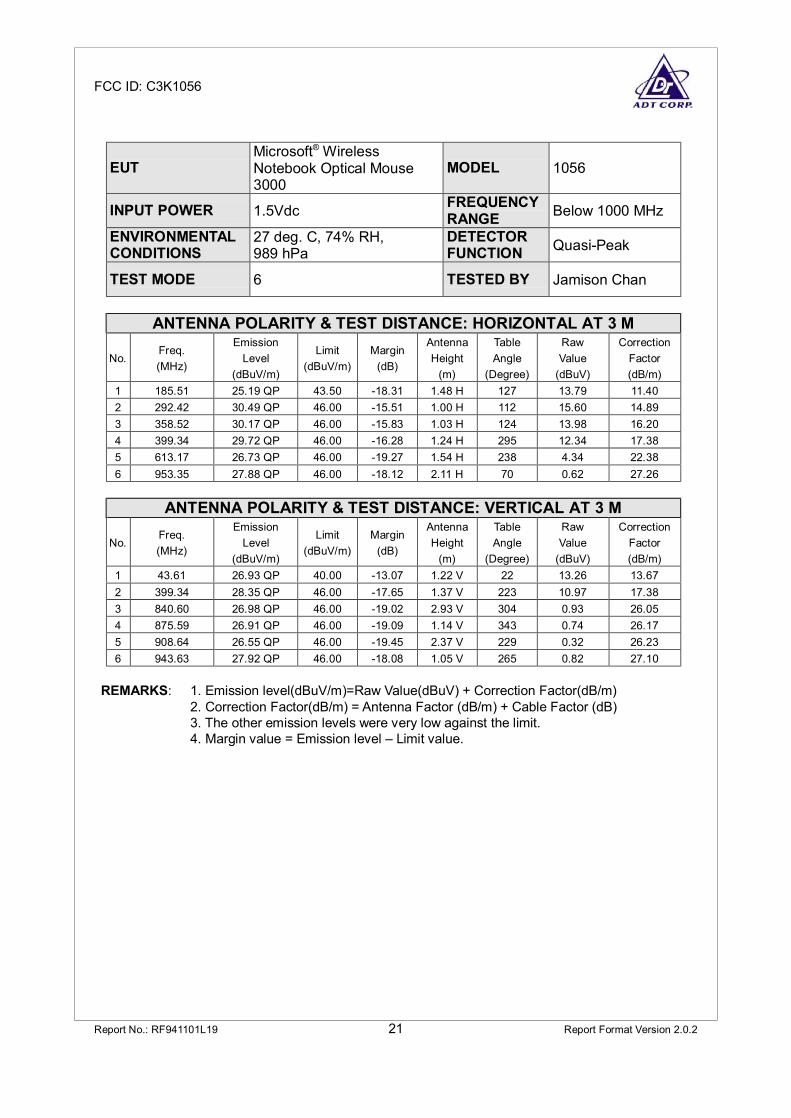
EUTMicrosoft® WirelessNotebook Optical Mouse3000
MODEL 1056
INPUT POWER 1.5Vdc FREQUENCYRANGE Below 1000 MHz
ENVIRONMENTALCONDITIONS
27 deg. C, 74% RH,989 hPa
DETECTORFUNCTION Quasi-Peak
TEST MODE 6 TESTED BY Jamison Chan
ANTENNA POLARITY & TEST DISTANCE: HORIZONTAL AT 3 M
No.Freq.(MHz)
EmissionLevel
(dBuV/m)
Limit(dBuV/m)
Margin(dB)
AntennaHeight
(m)
TableAngle
(Degree)
RawValue
(dBuV)
CorrectionFactor(dB/m)
1 185.51 25.19 QP 43.50 -18.31 1.48 H 127 13.79 11.402 292.42 30.49 QP 46.00 -15.51 1.00 H 112 15.60 14.893 358.52 30.17 QP 46.00 -15.83 1.03 H 124 13.98 16.204 399.34 29.72 QP 46.00 -16.28 1.24 H 295 12.34 17.385 613.17 26.73 QP 46.00 -19.27 1.54 H 238 4.34 22.386 953.35 27.88 QP 46.00 -18.12 2.11 H 70 0.62 27.26
ANTENNA POLARITY & TEST DISTANCE: VERTICAL AT 3 M
No.Freq.(MHz)
EmissionLevel
(dBuV/m)
Limit(dBuV/m)
Margin(dB)
AntennaHeight
(m)
TableAngle
(Degree)
RawValue
(dBuV)
CorrectionFactor(dB/m)
1 43.61 26.93 QP 40.00 -13.07 1.22 V 22 13.26 13.672 399.34 28.35 QP 46.00 -17.65 1.37 V 223 10.97 17.383 840.60 26.98 QP 46.00 -19.02 2.93 V 304 0.93 26.054 875.59 26.91 QP 46.00 -19.09 1.14 V 343 0.74 26.175 908.64 26.55 QP 46.00 -19.45 2.37 V 229 0.32 26.236 943.63 27.92 QP 46.00 -18.08 1.05 V 265 0.82 27.10
REMARKS: 1. Emission level(dBuV/m)=Raw Value(dBuV) + Correction Factor(dB/m) 2. Correction Factor(dB/m) = Antenna Factor (dB/m) + Cable Factor (dB)
3. The other emission levels were very low against the limit.4. Margin value = Emission level – Limit value.

FCC ID: C3K1056
Report No.: RF941101L19 22 Report Format Version 2.0.2
4 INFORMATION ON THE TESTING LABORATORIES
We, ADT Corp., were founded in 1988 to provide our best service in EMC, Radio,Telecom and Safety consultation. Our laboratories are accredited and approved bythe following approval agencies according to ISO/IEC 17025:
USA FCC, NVLAP, UL, A2LAGermany TUV RheinlandJapan VCCINorway NEMKOCanada INDUSTRY CANADA , CSAR.O.C. CNLA, BSMI, DGTNetherlands TeleficationSingapore PSB , GOST-ASIA(MOU)Russia CERTIS(MOU)
Copies of accreditation certificates of our laboratories obtained from approvalagencies can be downloaded from our web site: www.adt.com.tw/index.5/phtml. Ifyou have any comments, please feel free to contact us at the following:
Linko EMC/RF LabTel: 886-2-26052180Fax: 886-2-26052943
Hsin Chu EMC/RF LabTel: 886-3-5935343Fax: 886-3-5935342
Hwa Ya EMC/RF/Safety/Telecom LabTel: 886-3-3183232Fax: 886-3-3185050
Linko RF LabTel: 886-3-3270910Fax: 886-3-3270892
Email: [email protected] Site: www.adt.com.tw
The address and road map of all our labs can be found in our web site also.

FCC ID: C3K1056
Report No.: RF941101L19 23 Report Format Version 2.0.2
APPENDIX-A
MODIFICATIONS RECORDERS FOR ENGINEERING CHANGES TOTHE EUT BY THE LAB
No any modifications are made to the EUT by the lab during the test.