Embed Size (px)
Citation preview

FAULT TREE ANALYSIS OF KNICS RPS SOFTWARE
GEE-YONG PARK1*, KWANG YONG KOH2, EUNKYOUNG JEE2, POONG HYUN SEONG2, KEE-CHOON KWON1,and DAE HYUNG LEE3
1Korea Atomic Energy Research Institute, 1045 Daedeok-daero, Yuseong, Daejeon, 305-353, Republic of Korea
2Korea Advanced Institute of Science and Technology, 373-1 Guseong, Yuseong, Daejeon, 305-701, Republic of Korea
3Doosan Heavy Industries & Construction, 39-3 Seongbok, Suji, Yongin, Gyeonggi-do, 448-795, Republic of Korea
*Corresponding author. E-mail : [email protected]
Received July 2, 2007 Accepted for Publication April 12, 2008
1. INTRODUCTION
A fully-digitalized reactor protection system, theKNICS RPS, is being developed under the KNICSproject for use in newly-constructed nuclear power plantsand also in the upgrade of existing analog-based reactorprotection systems (RPSs) [1]. The KNICS RPS has fourchannels which are located in electrically and physicallyisolated rooms. The KNICS RPS is composed of a groupof bistable processors (BPs) which redundantly compareprocess variables with their corresponding setpoints anda group of coincidence processors (CPs) that generate atrip signal when a trip condition is satisfied by the two-out-of-four voting logic for the trip signals from the BPs.All the trip-actuating functions in the BPs and CPs areimplemented in the software.
The software in the KNICS RPS is crucial to thesafety of a nuclear power plant in that its malfunctionmay result in irreversible consequences. The trip-functioning software in the KNICS RPS is thus classifiedas safety-critical. According to the code and standard[2][3], it is required that an SSA be performed for safety-critical software in the trip-functioning processors.
Various standards, including IEC and IEEE standards,have been investigated and compared in order to establisha proper safety analysis process for the safety-criticalsoftware in the KNICS project, where not only a digitalRPS, but a programmable logic controller (PLC) with aproprietary operating system, which is called a POSAFE-Q PLC, is being developed. Fig.1 shows the safetyanalysis process in the KNICS RPS and POSAFE-Q PLC.As can be seen in Fig.1, the software HAZOP (Hazardand Operability) is used in the SSA at the requirementsphase, and the software HAZOP [4] and the softwareFTA techniques are used in the design and implementation(code) phases. Among the techniques used in the SSA,this paper describes the application of the software FTAto the safety-critical software of the KNICS RPS at thedesign phase and presents the analysis results.
2. EFFORTS OF SOFTWARE ERROR REDUCTIONAND THE SSA
The software used in the KNICS RPS is beingdeveloped under a rigorous procedure [1], and the
This paper describes the application of a software fault tree analysis (FTA) as one of the analysis techniques for asoftware safety analysis (SSA) at the design phase and its analysis results for the safety-critical software of a digital reactorprotection system, which is called the KNICS RPS, being developed in the KNICS (Korea Nuclear Instrumentation &Control Systems) project. The software modules in the design description were represented by function blocks (FBs), and thesoftware FTA was performed based on the well-defined fault tree templates for the FBs. The SSA, which is part of theverification and validation (V&V) activities, was activated at each phase of the software lifecycle for the KNICS RPS. At thedesign phase, the software HAZOP (Hazard and Operability) and the software FTA were employed in the SSA in such a waythat the software HAZOP was performed first and then the software FTA was applied. The software FTA was applied tosome critical modules selected from the software HAZOP analysis.
KEYWORDS : Software Safety Analysis, Software Fault Tree Analysis, Digital Reactor Protection System
397NUCLEAR ENGINEERING AND TECHNOLOGY, VOL.40 NO.5 AUGUST 2008

independent V&V activities are being arranged [5]. Fig.2shows the V&V activities performed by an independentV&V team for the development of the KNICS RPSsoftware. The purposes of the V&V activities are toensure that the KNICS software product satisfies theregulatory acceptance criteria and to improve thesoftware quality by finding and resolving softwaredefects at an early phase during software development.For achieving these purposes, various plans are providedand documented at the planning phase. The developmentof and the V&V activities for the KNICS RPS softwareare performed according to these plan documents. Forthe V&V activities during the requirements and designphases, various document evaluations such as thelicensing suitability evaluation, the detailed inspection bya Fagan inspection [6], and the traceability analysis areactivated. Formal verifications are carried out for theformal specifications by the use of CASE tools. From theimplementation phase, the major V&V activity is thesoftware testing. As can be seen in Fig.2, two activitiesother than the activities described above are presented.One is an SSA, and the other software configurationmanagement. These two activities are combined into theV&V activities in order to satisfy the software qualityassurance established in the KNICS project. Thus, theSSA in the KNICS project is part of the V&V activities,as shown in Fig.2.
There are usually four categories of technicalmethods for achieving highly dependable software: fault
398 NUCLEAR ENGINEERING AND TECHNOLOGY, VOL.40 NO.5 AUGUST 2008
PARK et al., Fault Tree Analysis of KNICS RPS Software
Fig.2 Software V/V Activities of KNICS RPS
Fig.1 Software Safety Analysis Process for KNICS Project

prevention, fault removal, fault tolerance, and fault (orfailure) prediction [7]. Fault prevention is a means forpreventing a fault occurrence or introduction. It containsthe use of good software design methods, theenforcement of a structured programming discipline, theemployment of formal methods, and so forth. In thedevelopment of the KNICS RPS software, the formalspecifications/modularizations based on the proprietaryCASE tools [8] and some design/coding guidelines areallocated to this category. Fault removal is a means forreducing the presence of faults. The V&V activities andthe SSA in Fig.2 are included in this category. Faulttolerance is for ensuring a service capable of fulfilling asystem’s function in the presence of faults and, to a lesserextent, watchdog timers in the KNICS RPS may beallocated to this category. Fault prediction refers toestimating the present number, future incidence, andconsequences of faults. For this category, althoughnumerous methods have been proposed, there are fewstandard methods with an inter-disciplinary consensuswhich are applicable to a rare failure event of highlydependable software such as the KNICS RPS software.
3. STRATEGY FOR APPLICATION OF SOFTWAREFTA
As can be seen in Fig.1, the software safety processbegins by establishing a software safety plan based on apreliminary system hazard analysis. The SSA activitiesin the requirements, design, and implementation phasesare carried out according to the software safety plan. Thepurpose of applying the software HAZOP and thesoftware FTA to a software system at the design phase isto identify a defect or hazard in the software modulesthat can induce or affect the system hazards acquiredfrom a preliminary system hazard analysis or a review ofthe system-level hazard analysis by an FMEA (FailureModes and Effects Analysis). For the KNICS RPS, thesoftware-contributable system hazards were identifiedthrough a review of the system FMEA results, and theyare presented in Table 1. The criticality level in Table 1
is given relative to the severity of a hazard item. Level 4is the most significant hazard that can drive a plant to asevere accident, and level 1 indicates an insignificanthazard that seldom affects a system’s availability.
In an SSA at the design or implementation phase, thesoftware HAZOP was, at first, applied to the softwaremodules represented by a function block diagram (FBD)which is compatible with the POSAFE-Q PLC. Thesoftware HAZOP evaluated all the design specificationswith respect to all the software-contributable systemhazards in Table 1 [4], and the significant defective areasin the FBD modules were identified by this method. Thesoftware FTA was then applied to these defectivemodules to accurately identify a defective location or alogic error. In this study, the software FTA was appliedto only the software modules that can induce the firsthazard item. Thus, the software FTA is confined to anevent where a software module cannot generate a tripsignal when a trip condition for the software module issatisfied. Both methods are redundant and complementaryin that the software HAZOP is a forward (in fact, HAZOPis a bidirectional method, but, in this study, the forwardanalysis was weighted more) and broad-thinking analysismethod through team works of the HAZOP members,and, on the contrary, the SFTA is a backward and localsystematic analysis method by an individual analyst.
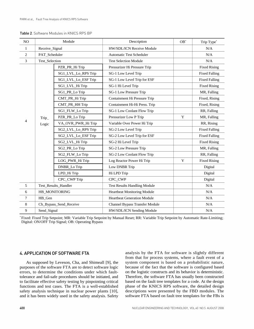
Based on the software-contributable system hazards,the interface points between the system hazards and thesoftware modules have been identified. Table 2 presentsthe software modules of a BP of the KNICS RPS.Actually, all the software modules have been examinedto identify the interface points for all the system hazards.In this study, the interface points for hazard item 1 areconsidered, and the candidate interface points whosefinal output can affect the most critical system hazard arethe trip-functioning modules represented by the bold redlines in Table 2. The software FTA is applied to some ofthese trip-functioning modules after being determinedfrom the software HAZOP analysis [4], and the interfacepoint through which a defective FBD module can affectthe most critical system hazard can be the location of atop event of the software FTA.
399NUCLEAR ENGINEERING AND TECHNOLOGY, VOL.40 NO.5 AUGUST 2008
PARK et al., Fault Tree Analysis of KNICS RPS Software
1 KNICS RPS cannot generate a trip signal when a trip condition for a process variable is satisfied. 4
2 KNICS RPS generates a trip signal when it should not generate a trip signal. 3
KNICS RPS cannot send qualified information of its operational status to the main control room
for an operator.
Table 1. System Hazards and Criticality Level for KNICS RPS
Item No. Criticality LevelSoftware Hazards
32
4. APPLICATION OF SOFTWARE FTA
As supposed by Leveson, Cha, and Shimeall [9], thepurposes of the software FTA are to detect software logicerrors, to determine the conditions under which fault-tolerance and fail-safe procedures should be initiated, andto facilitate effective safety testing by pinpointing criticalfunctions and test cases. The FTA is a well-establishedsafety analysis technique in nuclear power plants [10],and it has been widely used in the safety analysis. Safety
analysis by the FTA for software is slightly differentfrom that for process systems, where a fault event of asystem component is based on a probabilistic nature,because of the fact that the software is configured basedon the logistic constructs and its behavior is deterministic.Therefore, the software FTA has usually been constructedbased on the fault tree templates for a code. At the designphase of the KNICS RPS software, the detailed designdescriptions were presented by the FBD modules. Thesoftware FTA based on fault tree templates for the FBs is
400 NUCLEAR ENGINEERING AND TECHNOLOGY, VOL.40 NO.5 AUGUST 2008
PARK et al., Fault Tree Analysis of KNICS RPS Software
1
2
3
5
6
7
8
9
Receive_Signal
PAT_Scheduler
Test_Selection
PZR_PR_Hi Trip
SG1_LVL_Lo_RPS Trip
SG1_LVL_Lo_ESF Trip
SG1_LVL_Hi Trip
SG1_PR_Lo Trip
CMT_PR_Hi Trip
CMT_PR_HH Trip
SG1_FLW_Lo Trip
PZR_PR_Lo Trip
VA_OVR_PWR_Hi Trip
SG2_LVL_Lo_RPS Trip
SG2_LVL_Lo_ESF Trip
SG2_LVL_Hi Trip
SG2_PR_Lo Trip
SG2_FLW_Lo Trip
LOG_PWR_Hi Trip
DNBR_Lo Trip
LPD_Hi Trip
CPC_CWP Trip
Test_Results_Handler
HB_MONITORING
HB_Gen
Ch_Bypass_Send_Receive
Send_Signal
HW/SDL/ICN Receive Module
Automatic Test Scheduler
Test Selection Module
Pressurizer Hi Pressure Trip
SG-1 Low Level Trip
SG-1 Low Level Trip for ESF
SG-1 Hi Level Trip
SG-1 Low Pressure Trip
Containment Hi Pressure Trip
Containment Hi-Hi Press. Trip
SG-1 Low Coolant Flow Trip
Pressurizer Low P Trip
Variable Over Power Hi Trip
SG-2 Low Level Trip
SG-2 Low Level Trip for ESF
SG-2 Hi Level Trip
SG-2 Low Pressure Trip
SG-2 Low Coolant Flow Trip
Log Reactor Power Hi Trip
Low DNBR Trip
Hi LPD Trip
CPC_CWP
Test Results Handling Module
Heartbeat Monitoring Module
Heartbeat Generation Module
Channel Bypass Transfer Module
HW/SDL/ICN Sending Module
Y
Y
N/A
N/A
N/A
Fixed Rising
Fixed Falling
Fixed Falling
Fixed Rising
MR, Falling
Fixed, Rising
Fixed, Rising
RR, Falling
MR, Falling
RR, Rising
Fixed Falling
Fixed Falling
Fixed Rising
MR, Falling
RR, Falling
Fixed Rising
Digital
Digital
Digital
N/A
N/A
N/A
N/A
N/A
Table 2. Software Modules in KNICS RPS BP
NO Trip Type*Module Description OB*
Trip_
Logic4
* Fixed: Fixed Trip Setpoint; MR: Variable Trip Setpoint by Manual Reset; RR: Variable Trip Setpoint by Automatic Rate-Limiting;Digital: ON/OFF Trip Signal; OB: Operating Bypass

applied to a part of the software modules determinedfrom the software HAZOP, and the top node is onlyrelated to the most safety-critical hazard.
4.1 Construction of Software Fault Tree TemplatesThe fault tree templates are actually small fault trees
for their corresponding components in the software, andone more different aspect of the software FTA is that an
event in a fault tree template may be a logic operation,which is prohibited in the conventional FTA since all theevents that are linked together on a fault tree should bewritten as faults [10]. For a typical FB in the FBDmodule, a fault tree template is constructed in a way thatthe failure modes are extracted starting from the outputport of an FB, through the body of the FB, ending at theinput ports, as shown in Fig.3. The lower left event inFig.3 indicates plausible physical and functional faultswithin an FB, and the lower right event is for a logicoperation through which a template at the immediatelower tree level is attached to its upper-level template.
The fault tree templates for the FBs have beenproposed by Oh and her colleagues [11]. Oh [12]classified fault cases rigorously and derived each FB’stemplate based on these fault cases. The fault treetemplates are composed of two distinguishing parts: oneis the fault events and the other the cause/effect events.One purpose for the introduction of the cause/effectevents is to indicate fault propagation and also to help ananalyst understand the logical operation of a functionblock. From the experience of applying the fault treetemplates to the safety-critical software of the KNICSRPS, it was found that, before the construction of asoftware FTA, analysts usually reviewed in advance thefunction block diagram in great detail and they wereinclined to focus more on fault/failure cases because theyalready understood the logical flow of an FBD module.Thus, in this study, the templates for the FBs wererefined to be more fault-oriented and concise.
401NUCLEAR ENGINEERING AND TECHNOLOGY, VOL.40 NO.5 AUGUST 2008
PARK et al., Fault Tree Analysis of KNICS RPS Software
Fig.3 Overall Architecture for Constructing Fault TreeTemplates for Function Blocks
Fig.4 Fault Tree Template for the AND Function Block

The types of the FBs used in the FBD modules aredivided into five classes: Logic Operation FB (AND/OR),Comparison FB (GE/GT/LE/LT/EQ), Selection FB (SEL),Algebraic Operation FB (ADD/SUB/MUL/DIV/ABS),and Timer FB (TON). The TON is activated in such away that if the IN value is 1 and the PT value is set to an
appropriate value, then the output of the TON becomes 1when the internal count is equal to or larger than the PTvalue. Figs.4-8 display the modified fault tree templatesfor the representative FBs for the five function types. Thefault events in a fault tree template are derived based onthe fault criteria proposed by Oh [12]. In Figs.4-8, the
402 NUCLEAR ENGINEERING AND TECHNOLOGY, VOL.40 NO.5 AUGUST 2008
PARK et al., Fault Tree Analysis of KNICS RPS Software
Fig.5 Fault Tree Template for the GE Function Block
Fig.6 Fault Tree Template for the SEL Function Block

box with a circle at the bottom means a basic event, thebox with a triangle represents an event that has moretrees presented on another page, and the one with arectangle indicates that a further analysis for a lower-level tree could progress through this event. An OR- orAND-gate symbol below a box performs a logical OR orAND operation for its inputs.
4.2 Software FTAThe software modules selected from the results of the
software HAZOP for the BP FBD modules in Table 2 areSG1_FLW_Lo Trip (Steam Generator #1 Low CoolantFlow Trip), PZR_PR_LO Trip (Pressurizer Low PressureTrip), VA_OVR_PWR_Hi Trip (Variable Over-Power
High Trip), and DNBR_Lo Trip (Low DNBR Trip). Todemonstrate the results of the software FTA, the safetyanalysis for the trip module of VA_OVR_PWR_Hi Tripis presented in this paper. The VA_OVR_PWR_Hi Tripmodule generates a trip signal for the shutdown of anuclear reactor when the neutron flux is increasing with arate of change larger than the acceptable rate at a low-power startup time or the value of the neutron flux exceedsthe maximum limit at the rated power. It is furthercomposed of sub-modules such as TRIP_DECISION,TRIP_OPERATION, SETPT_CAL, and TEST_SEL.Among the sub-modules in the VA_OVR_ PWR_Hi Tripmodule, the TRIP_OPERATION, which is a major sub-module, is selected for the application of the software FTA.
403NUCLEAR ENGINEERING AND TECHNOLOGY, VOL.40 NO.5 AUGUST 2008
PARK et al., Fault Tree Analysis of KNICS RPS Software
Fig.7 Fault Tree Template for the ADD Function Block
Fig.8 Fault Tree Template for the TON Function Block

A part of the FBD representation for theTRIP_OPERATION sub-module is shown in Fig.9where the function blocks are labeled, such as GE1. Theflow path (i.e., the sequence of execution) in the FBDmodules in Fig.9 is from left to right and from top to
bottom. For these FBD modules, the software FTA basedon the fault tree templates are constructed as inFigs.10(a)-(i), where the software FTA are pruned toleave meaningful trees. In Figs.10, an event box with adiamond symbol attached below it indicates that the
404 NUCLEAR ENGINEERING AND TECHNOLOGY, VOL.40 NO.5 AUGUST 2008
PARK et al., Fault Tree Analysis of KNICS RPS Software
Fig.9. FBD Module for VA_OVR_PWR_Hi Trip (TRIP_OPERATION)

event is not analyzed further because of a lack ofinformation or inappropriateness in doing so. An eventbox with a house symbol means that the event is natural.
For the TRIP_OPERATION sub-module, the finaloutput is the variable TRIP_LOGIC at the output port ofGE1 in Fig.9. When a trip condition is satisfied, thisvariable should be 1. Thus, the top event of the softwareFTA in Fig.10(a) is the event that TRIP_LOGIC=0 whena trip condition is satisfied in such a way that PV_OUT is
larger than _1_TSP (at GE2) with an internal count_1_TRIP_CNT being equal to or larger than a constant_1_MAXCNT (at GE1). It is apparent that this event isdue to an incorrect operation in GE1, leading to theconclusion that the input variable _1_TRIP_CNT of GE1has a problem with its updating procedure, as shown inthe event FUP_IN1_GE1 in Fig.10(a). In the lower partof Fig.10(a), this problem is traced to AND1 and GE2 inFig.9, and this fault back-tracking is divided into two
405NUCLEAR ENGINEERING AND TECHNOLOGY, VOL.40 NO.5 AUGUST 2008
PARK et al., Fault Tree Analysis of KNICS RPS Software

406 NUCLEAR ENGINEERING AND TECHNOLOGY, VOL.40 NO.5 AUGUST 2008
PARK et al., Fault Tree Analysis of KNICS RPS Software
Fig.10 Software FTA for VA_OVR_PWR_Hi Trip

paths: one is due to an incorrect calculation of the tripsetpoint _1_TSP at GE2 and the other due to an incorrectvalue of the input variable TRIP_LOGIC at AND1. Thefirst path is further arranged in Figs.10(b)-(f).
From Figs.10(b)-(f), it can be recognized that, when aprocess variable PV_OUT is decreasing, the interim tripsetpoint _1_TEMP_TSP at SEL4 is set to _1_TSP_t19rather than to _1_TEMP_TSP at IN1 of SEL4 though_1_TEMP_TSP at IN1 contains the correct trip setpoint.This fault results from the wrong operation betweenSUB1 and LT1 in Fig.9. Fig.10(f) reveals a defect in theoperational logic (i.e., for normal conditions, theoperation that _1_t19 - _1_TSP_t19 usually results in anegative value) between SUB1 and LT1. The aboveidentification means that, when the process variabledecreases, the trip setpoint remains unchanged with avalue of _1_TSP_t19 (the trip setpoint at 1 secondbefore). Thus, the difference between the trip setpointand the process variable becomes increasingly largerwhen the process variable continuously decreases. Aftera decreasing trend, if the process variable starts toincrease so fast that it can trigger the expected andcorrect trip setpoint, the trip signal cannot be generatedbecause the trip setpoint before an increasing trend hasbeen given to a much larger value than an expected andcorrect value.
The second fault path in Figs.10(g)-(i) is plausible inthe situation that a process variable has increased togenerate a trip signal (i.e., _1_TRIP = 1) and then itdecreased slightly to a value lower than the trip setpoint,but, at this time, the process variable increases suddenlyto a value above the trip setpoint. Figs.10(g)-(i) revealthat this phenomena can occur due to an incomplete resetprocedure of TRIP_LOGIC resulting from a defect in thereset logic of _1_TRIP_CNT. The reset process of_1_TRIP_CNT, as shown in the bottom right area ofFig.9, means that _1_TRIP_CNT becomes 0 when bothPV_OUT < _1_TSP and TRIP_LOGIC = 1 are satisfied,causing TRIP_LOGIC to be reset to 0 one step laterwhen PV_OUT < _1_TSP. Thus, when the software FTAis confined to the TRIP_OPERATION sub-module, thetrip triggering finally occurs with a one step delay.Generating a trig signal with a one step delay may violatethe system response time for the KNICS RPS.
As can be seen in Figs.10, the software FTA for apart of the VA_OVR_PWR_Hi Trip module has acomplex and lengthy tree structure where the softwareHAZOP seemed to be impossible to apply to pinpoint adefect. The logic errors described above have not beendetected even in a formal verification process. Though atesting may identify these errors, it is very difficult toelucidate these types of defects without delicate testcases with a profound test scenario. The results of thesoftware FTA could be used in providing delicate testcases for identifying defects containing these types oflogic errors.
5. RESULTS
For the safety analysis of the safety-critical software,the strategy and application procedure for the softwareFTA were presented in this paper. Based on the previousstudy of the fault tree templates for the function blocks,the fault-oriented templates were devised for theconvenient implementation of the software FTA.Because the software fault trees for an FBD module areusually very long and complex, the software FTA isapplied to critical portions of the FBD-based designmodules that are identified from the software HAZOP.Because of a different viewpoint from the V&Vactivities, the software FTA can obtain some valuableresults that have not been identified through a rigorousV&V procedure.
In the KNICS RPS software, the software HAZOPand the software FTA are used in the SSA at the designphase. The application of both methods is supposed to beredundant, and this redundancy obviously requires anadditional, but overlapping, work for the SSA. This typeof overlap is thought to be meaningful because all thecurrent safety analysis methods have their own meritsand demerits.
REFERENCES_______________________________[ 1 ] J. H. Park, D. Y. Lee, C. H. Kim, “Development of KNICS
RPS Prototype”, Proceedings of ISOFIC 2005, Session 6,pp.160-161, Tongyeong, Korea, Nov. 1~4, 2005.
[ 2 ] NUREG-0800, Rev.04, “Standard Review Plan: BTPHICB–14, Guidance on Software Reviews for DigitalComputer-Based Instrumentation and Control Systems,”U.S. Nuclear Regulatory Commission, 1997.
[ 3 ] IEEE Std-1228, “Software Safety Plan”, Institute ofElectrical and Electronic Engineers, 1994.
[ 4 ] G. Y. Park, J. S. Lee, S. W. Cheon, K. C. Kwon, E. Jee,and K. Y. Koh, “Safety Analysis of Safety-CriticalSoftware for Nuclear Digital Protection System”, LectureNotes in Computer Science, Vol.4680, pp.148-161, 2007.
[ 5 ] K. C. Kwon and G. Y. Park, “Formal Verification andValidation of the Safety-Critical Software in Digital ReactorProtection System”, NPIC & HMIT 2006, pp.1371-1376,Nov. 12~16, Albuquerque, NM, USA, 2006.
[ 6 ] M. E. Fagan, “Design and Code Inspections to ReduceErrors in Program Development”, IBM System Journal,Vol.15, No.3, pp.182-211, 1976.
[ 7 ] M. R. Lyu, Handbook of Software Reliability Engineering,McGraw-Hill, pp.29, 1996.
[ 8 ] J. Yoo and S. Cha, “A Formal Software RequirementsSpecification Method for Digital Plants ProtectionSystems”, CS/TR 2003-191, Department of ComputerScience, KAIST, 2003.
[ 9 ] N. G. Leveson, S. Cha, and T. J. Shimeall, “SafetyVerification of Ada Programs using Software FaultTrees,” IEEE Software, pp.48-59, July 1991.
[ 10 ] W. E. Vesely, F. F. Goldberg, N. H. Reberts, and D. F.Haasl, Fault Tree Handbook, NUREG-C492, U. S.Nuclear Regulatory Commission, 1981.
407NUCLEAR ENGINEERING AND TECHNOLOGY, VOL.40 NO.5 AUGUST 2008
PARK et al., Fault Tree Analysis of KNICS RPS Software

[ 11 ] Y. Oh, J. Yoo, S. Cha, and H. S. Son, “Software SafetyAnalysis of Function Block Diagrams using Fault Trees”,Reliability Engineering and System Safety, Vol.88,pp.215-228, 2005.
[ 12 ] Y. Oh, Safety Analysis of Function Block Diagrams usingFault Trees, M.S. Thesis, EECS Department, KoreaAdvanced Institute of Science and Technology, Korea,2004.
408 NUCLEAR ENGINEERING AND TECHNOLOGY, VOL.40 NO.5 AUGUST 2008
PARK et al., Fault Tree Analysis of KNICS RPS Software


![Fault Tree Diagram[1]](https://img.pdfslide.us/doc/110x75/55cf8c8a5503462b138d7284/fault-tree-diagram1.jpg)