Embed Size (px)
Citation preview
Composite Structures 134 (2015) 654–662
Contents lists available at ScienceDirect
Composite Structures
journal homepage: www.elsevier .com/locate /compstruct
Fatigue damage tolerance of two tapered composite patch configurations
http://dx.doi.org/10.1016/j.compstruct.2015.08.1140263-8223/� 2015 Elsevier Ltd. All rights reserved.
⇑ Corresponding author. Tel.: +61 3 9902 0113.E-mail address: [email protected] (W. Yan).
Chao Wu a,b, Andrew J. Gunnion b,c, Bernard Chen a, Wenyi Yan a,⇑aDepartment of Mechanical and Aerospace Engineering, Monash University, Clayton, Vic. 3168, AustraliabCooperative Research Centre for Advanced Composite Structures Ltd., 1/320 Lorimer Street, Port Melbourne, Vic. 3207, AustraliacAdvanced Composite Structures Australia, 1/320 Lorimer Street, Port Melbourne, Vic. 3207, Australia
a r t i c l e i n f o
Article history:Available online 3 September 2015
Keywords:Damage toleranceFatigueSkin doubler repairStepped doubler repairPly-drop doubler repair
a b s t r a c t
To avoid high peel stresses around the perimeter of a bonded composite patch repair, the patch thicknessoften tapers to a fine edge. This paper investigates and compares the damage tolerance of two differentconfigurations of taper design under fatigue loading with different size of initial bondline flaws. Thebondline damage at the tip of the doubler repair was simulated by an initial flaw which was createdthrough a Teflon tape. A constant amplitude fatigue loading was applied to all specimens. The crackpropagation against the number of cycles was recorded and the fatigue life when the crack reached100 mm from the doubler tip was reported. Microscope investigations were conducted and providedmicro scale evidence on the effects of initial flaw size on the crack initiation pattern of the two doublerdesign configurations. Finally, the damage tolerance of the two configurations were compared andconclusions were drawn with implications for the design of composite patch repairs. It was found thatply-drop doubler joints showed better damage tolerance than stepped doubler joints under fatigueloading. The experimental results suggested a threshold size of 5 mm for the doubler tip flaw, if anyinspection technology should be adopted for damage detection.
� 2015 Elsevier Ltd. All rights reserved.
1. Introduction
Fibre reinforced polymer (FRP) composites have been adoptedas construction materials for automotive, aerospace, civil and mar-ine structures [1–5]. Suitable methods are required when repairingdamaged composite parts [6–10] to restore their designed capaci-ties. Two methods are currently widely adopted in compositestructures, namely mechanical fastening and adhesive bonding. Ithas been widely reported that adhesive bonding has benefits suchas lighter weight, better load transferring mechanism throughlarger bonded area and better fatigue performance [1,11–16]. Onthe other hand, mechanical fastening methods using bolts or rivetswere always criticised due to stress concentration resulting fromfibre cutting at bolt holes, and increasing the self-weight ofstructure [1,14,17]. The weight saving is especially more importantin modern airplane structures where FRP composites become moreextensively used (e.g. Boeing 787 with about 50% FRP by weight[18]), which makes the adhesive bonding methods more desirable[14].
There has been an increase in the demand of replacing mechan-ically fastened metallic patches with bonded composite patch
repair to increase the service life in aircraft operations [19,20].However, as there is currently no accepted technology for inspect-ing the quality of the bondline, the application of bonded repairs toprimary structure is limited [21,22]. Another issue with adhesiverepairs is the lack of inspection method and analytical solutionas well as damage tolerance information for ensuring the bondlineintegrity [6,23]. To credit a bonded patch repair of structural dam-age to primary aircraft structure, it must restore the static strength,stiffness, damage tolerance and fatigue performance of the originalstructure. Baker [20] characterised the bonded patch repair intotwo zones: the middle part of the repair was named ‘damage-tolerant zone’ and the tapered ends of the patch was called‘safe-life zone’. Two types of joints, doubler overlap joint and skindoubler joint, were proposed as the generic joints to assess thedamage tolerance of the damage-tolerant zone and the safe-lifezone, respectively.
There have been studies on the damage tolerance of bondedcomposite patch repair under fatigue loading in the literature.However, most of the work was conducted on repairing of crackedaluminium adherends [19,20,24–26]. For example, the certificationrequirements on giving full credit to bonded carbon fibre patchrepair in slowing crack growth and recovering residual strengthof parent aluminium structure were addressed in [20]. Concernswere given to effects of fatigue and environmental durability onthe patching efficiency. The skin doubler specimens were proposed
C. Wu et al. / Composite Structures 134 (2015) 654–662 655
in [20] for characterising the threshold for damage growth in thesafe-life zone, which was used in the design of F111 repair in[27]. Charlkley et al. [24] presented an experimental study on theskin doubler specimens prepared by bonding composite skindoubler repair on aluminium adherend. The skin doubler consistedof eleven plies of unidirectional boron/epoxy and was bonded tothe aluminium adherend by FM 73 adhesive. Since the purposeof the study was to determine the debonding initiation load, noinitial flaw was introduced in the bondline. The specimens weresubjected to constant amplitude fatigue load with a specific loadratio (min/max) at a frequency of 3 Hz. The disbond load wasobtained when the strain at the doubler tip dropped by 10%. Itreported that, the disbond initiation and propagation locationswere dependent on the shape of the skin doubler tip. For skindoubler without a tapered tip (sharp end), the disbond was withinthe boron/epoxy ply adjacent to the adhesive bondline. For skindoubler repair with a tapered tip, the disbond tended to be mixed:some failure within the ply of boron/epoxy adjacent to the adhe-sive bondline and some failure at the interface between aluminiumand adhesive. The disbond initiation loads of skin doubler repairswith different tip shapes indicated that adhesive stress was not asuitable parameter for describing the disbond initiation of thebondline. Poole [25] reported an experimental programme on thedamage tolerance of skin doubler repairs to the cracked aluminiumadherend under fatigue loading. Two types of skin doubler repairswere adopted: one was twelve plies unidirectional boron/epoxypatch and the other was sixteen plies unidirectional graphite/epoxy patch. The two patches were 132 mm long and 70 mmwide.Redux 312/5 was used as adhesive bonding the patches to the2024-T3 aluminium panel of 145 mm wide and 4 mm thick. Initialflaw with a size of 8 � 10 mm2 was embedded in the bondline attwo locations. One was at the tip of the skin doubler repair andthe other was located at the side edge of the skin doubler repairimmediately covering the crack of the aluminium adherend. Spec-imens were tested under 110 MPa constant amplitude fatigueloading with a load ratio of 0.05. The experimental results indi-cated that no debond growth was detected for initial flaw at thetapered edge of the skin doubler repair until the aluminium panelfractured. When located at the side edge of the patch repair cover-ing the crack of the aluminium panel, the initial flaw (8 � 10 mm2)grew with the aluminium crack under fatigue loading but had littleeffect on the fatigue life. Roach [26] reported a similar experimen-tal program on the damage tolerance of boron/epoxy compositetapered skin doubler repair bonded to 2024-T3 aluminium adher-end. The tapered skin doubler patch consisted thirteen plies boron/epoxy (type 5521/4) with a stacking sequence of (0/+45/�45/90)3.FM-3 was used as adhesive. The stiffness ratio between skin dou-bler and aluminium was 1.2. The initial flaw (0.7500 or 100 diameter)at the tip of the skin doubler repair was created by Teflon tape.Specimens were tested under fatigue loading at a range of 25.86–143.06 MPa. The experimental results showed that the large initialbondline flaw at the tip of the tapered skin doubler repair did notdecrease the overall composite doubler performance. The size ofthe initial flaw remained almost unchanged until the fracture ofthe cadmium plate under fatigue loading.
It should be noted that, the above mentioned studies were allconducted on the damage tolerance of skin doubler repairs whenbonded to aluminium adherends. Considering the increasing useof the fibre composite in airplane primary structures, it is neces-sary to understand the damage tolerance of skin doubler repairswhen bonded to composite adherends. However, the existingexperiences in aluminium adherends cannot be directly trans-ferred to composite adherends which may have different disbond-ing and damage mechanisms. This paper presents an experimentalstudy on the damage tolerance of tapered skin doubler repairs
bonded on graphite/epoxy laminate adherend when subjected tofatigue loading.
Two types of tapered skin doubler joints, representative ofrepairs, were compared in this paper, named stepped doublerand ply-drop doubler, in terms of sensitivity of their fatiguebehaviours to the embedded initial bondline flaw. Various initialflaws were introduced in the doubler bondline, by changing theflaw length and flaw width. Constant amplitude fatigue loadingwas determined through laminate coupon tests, to ensure amicrostrain of 2800 is obtained in the laminate adherends underthe peak load. The crack propagation was monitored and measuredby a microscope during the fatigue loading. Fatigue life wasdetermined when the crack reached a length of 100 mm. If therewas no crack growth or the crack grew but did not reach the lengthof 100 mm, the fatigue loading was applied continuously up to180,000 cycles. The failure modes, fatigue life and microscopeobservations of the crack initiation of both stepped and ply-dropdoublers were reported and compared. The results of the workprovide fatigue performance data that can be used to aid repairdesign, and to validate analysis methods.
2. Experimental program
2.1. Materials
Unidirectional graphite/epoxy ply of IM7/977-3 was used toprepare the laminate adherend and the skin doubler repair. Thematerial properties adopted in subsequent analysis are based onthose from Ref. [28] and listed in Table 1. Film adhesive FM300-2K was used to bond the doubler repair to the laminate adherend.The nominal weight of FM300-2K is 391 gsm with a nominal thick-ness of 0.33 mm. The lap shear strength at 24 �C is 40.7 MPa [29].
2.2. Skin doubler joint specimens with initial flaws
Thirty plies of IM7/977-3 were used to prepare the adherendand doubler laminate with a stacking sequence of [45/0/0/�45/90]3S.This layup represents laminate more likely found in an aircraftstructure (eg. wing skin) where the layup has been optimised. Eachply of IM7/977-3 is 0.13 mm thick resulting in a nominal thicknessof 3.9 mm for both laminate adherend and skin doubler repair.
Two types of doubler repair were selected. The first configura-tion (referred to as a ‘‘stepped taper” herein) is achieved byterminating each successive ply in the patch at a fixed distanceshort of the preceding ply. With this configuration, the first plyof the repair (adjacent to the bondline) is the longest ply. The sec-ond configuration (referred to as a ‘‘ply-drop taper” herein) isachieved with the shortest ply being placed adjacent to the bond-line and each subsequent ply extending a fixed length beyondthe preceding ply. The recommended doubler design is generallythe ply-drop doubler, however there may be instances where thestepped doubler configuration is adopted, particularly if laminat-ing/bonding pre-cured straps (e.g. battle damage repair [25]). Thedoubler panel was manufactured by staggering equal-size plieswith a 3 mm offset to achieve the stepped taper at one end, andthe ply-drop taper at the other, as shown in Fig. 1.
The parent laminate was manufactured in the same process asthe skin doubler panel but without tapered ends. The top andbottom surfaces of the parent laminate were made smooth witha caul plate, whilst the top surface of the doubler panel wasprepared with a silicon intensifier. When bonding the tapered skindoubler repair to the parent laminate, the adhering surfaces of thepanels were degreased with Methyl Ethyl Ketone (MEK). ThenFM300-2K was used as adhesive and cured under full vacuum con-dition in an oven at 125 �C for 120 min. The detailed configurations

Table 1Material data of IM7/977-3.
Properties Unit Value
Longitudinal modulus MPa 164,100Transverse modulus MPa 9860In-plane shear modulus MPa 4950Out-of-plane shear modulus MPa 2944Longitudinal Poisson’s ratio – 0.33Transversal Poisson’s ratio – 0.34
Fig. 1. Schematic of tapered panel manufacture.
656 C. Wu et al. / Composite Structures 134 (2015) 654–662
of stepped and ply-drop doublers are shown in Fig. 2, with thedoubler repair above the bondline (red line in Fig. 2) and parentlaminate under the bondline.
The cured skin doubler repaired laminate panel was cut intostrips of 360 mm long and 20 mm wide. The initial flaws at thetip of the tapered skin doubler repair were introduced using sheetsof Teflon, secured with tape on the parent laminate during bondingof the doubler. Two types of initial flaws were prepared with one
Fig. 2. (a) Stepped double; (b) ply-drop doubler (the red line represents the bondline)referred to the web version of this article.)
Fig. 3. Detailed dimensions of the skin doubler repaired specimen, and location
through width flaw (20 mm wide the same as the width of thespecimen), and the other partial width flaw (5 mm wide and5 mm long). Three lengths were selected for the full width flaw,which were 5 mm, 10 mm and 20 mm. A ‘‘pristine” control speci-men without an artificial flaw was also prepared for comparisonpurposes. The detailed dimensions of the skin doubler repairedspecimen, as well as the location and dimensions of the fullwidth flaw and partial width flaw are shown in Fig. 3. As can beseen in Fig. 3, a spacer (cut from the same panel as the parentlaminate) of 70 mm long, 20 mm wide and 3.9 mm thick wasbonded on the other end of the specimen. This was for clampingpurpose when applying the fatigue loading, to avoid any loadingeccentricity.
For each of the four initial flaw sizes, three identical specimenswere prepared for repeating purpose. Three control specimenswithout initial flaw were also manufactured for comparisonpurpose. Therefore, a total of thirty specimens were prepared withfifteen stepped doubler repaired specimens and fifteen ply-dropdoubler repaired specimens. The specimens with flaw length andflaw width are listed in Table 2. Each specimen has a label of‘A-Length �Width-ID’, where the first letter represents thedoubler type (i.e. ‘S’ for stepped doubler and ‘P’ for ply-dropdoubler), followed by the flaw size (Length �Width), and the lastnumber indicates the ID of repeating specimen.
2.3. Determination of fatigue loading
It was required that a strain of 2800 le should be achieved onthe surface of the parent laminate adherend under the maximumfatigue loading. This strain level was chosen to match other fatiguetests performed within the project, and provided an acceleratedbut representative fatigue loading for a military aircraft, whereone lifetime equals 30,000 cycles. Therefore, static coupon testswere conducted to determine the maximum amplitude of fatigueloading.
The laminate coupon was made of forty plies of IM7/977-3with the same stacking sequence as the parent laminate of[45/0/0/�45/90]4S. The coupon was 400 mm long. The measuredwidth and thickness were 20.19 mm and 5.36 mm, respectively.The coupon tests were conducted on an Instron machine with acapacity of 50 kN. Two strain gauges were attached on both sidesin the middle of the coupon. The strain gauges were CEA-06-
. (For interpretation of the references to colour in this figure legend, the reader is
and dimensions of the full width flaw and partial width flaw (unit in mm).
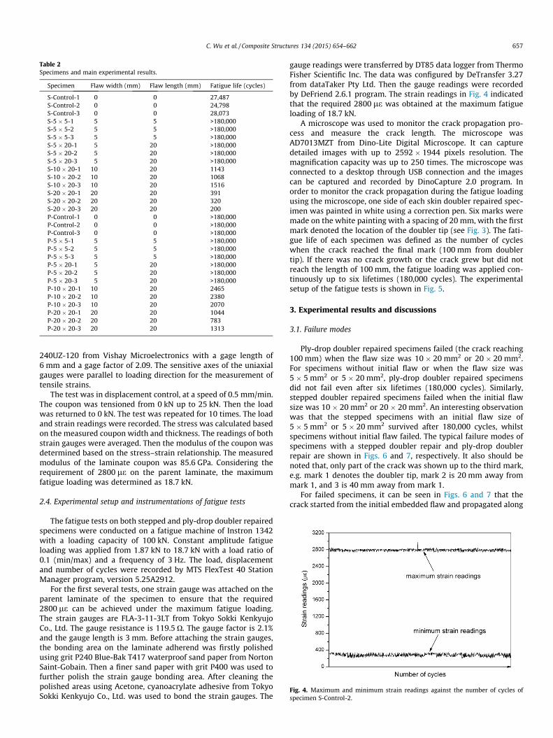
Table 2Specimens and main experimental results.
Specimen Flaw width (mm) Flaw length (mm) Fatigue life (cycles)
S-Control-1 0 0 27,487S-Control-2 0 0 24,798S-Control-3 0 0 28,073S-5 � 5-1 5 5 >180,000S-5 � 5-2 5 5 >180,000S-5 � 5-3 5 5 >180,000S-5 � 20-1 5 20 >180,000S-5 � 20-2 5 20 >180,000S-5 � 20-3 5 20 >180,000S-10 � 20-1 10 20 1143S-10 � 20-2 10 20 1068S-10 � 20-3 10 20 1516S-20 � 20-1 20 20 391S-20 � 20-2 20 20 320S-20 � 20-3 20 20 200P-Control-1 0 0 >180,000P-Control-2 0 0 >180,000P-Control-3 0 0 >180,000P-5 � 5-1 5 5 >180,000P-5 � 5-2 5 5 >180,000P-5 � 5-3 5 5 >180,000P-5 � 20-1 5 20 >180,000P-5 � 20-2 5 20 >180,000P-5 � 20-3 5 20 >180,000P-10 � 20-1 10 20 2465P-10 � 20-2 10 20 2380P-10 � 20-3 10 20 2070P-20 � 20-1 20 20 1044P-20 � 20-2 20 20 783P-20 � 20-3 20 20 1313
Fig. 4. Maximum and minimum strain readings against the number of cycles ofspecimen S-Control-2.
C. Wu et al. / Composite Structures 134 (2015) 654–662 657
240UZ-120 from Vishay Microelectronics with a gage length of6 mm and a gage factor of 2.09. The sensitive axes of the uniaxialgauges were parallel to loading direction for the measurement oftensile strains.
The test was in displacement control, at a speed of 0.5 mm/min.The coupon was tensioned from 0 kN up to 25 kN. Then the loadwas returned to 0 kN. The test was repeated for 10 times. The loadand strain readings were recorded. The stress was calculated basedon the measured coupon width and thickness. The readings of bothstrain gauges were averaged. Then the modulus of the coupon wasdetermined based on the stress–strain relationship. The measuredmodulus of the laminate coupon was 85.6 GPa. Considering therequirement of 2800 le on the parent laminate, the maximumfatigue loading was determined as 18.7 kN.
2.4. Experimental setup and instrumentations of fatigue tests
The fatigue tests on both stepped and ply-drop doubler repairedspecimens were conducted on a fatigue machine of Instron 1342with a loading capacity of 100 kN. Constant amplitude fatigueloading was applied from 1.87 kN to 18.7 kN with a load ratio of0.1 (min/max) and a frequency of 3 Hz. The load, displacementand number of cycles were recorded by MTS FlexTest 40 StationManager program, version 5.25A2912.
For the first several tests, one strain gauge was attached on theparent laminate of the specimen to ensure that the required2800 le can be achieved under the maximum fatigue loading.The strain gauges are FLA-3-11-3LT from Tokyo Sokki KenkyujoCo., Ltd. The gauge resistance is 119.5 O. The gauge factor is 2.1%and the gauge length is 3 mm. Before attaching the strain gauges,the bonding area on the laminate adherend was firstly polishedusing grit P240 Blue-Bak T417 waterproof sand paper from NortonSaint-Gobain. Then a finer sand paper with grit P400 was used tofurther polish the strain gauge bonding area. After cleaning thepolished areas using Acetone, cyanoacrylate adhesive from TokyoSokki Kenkyujo Co., Ltd. was used to bond the strain gauges. The
gauge readings were transferred by DT85 data logger from ThermoFisher Scientific Inc. The data was configured by DeTransfer 3.27from dataTaker Pty Ltd. Then the gauge readings were recordedby DeFriend 2.6.1 program. The strain readings in Fig. 4 indicatedthat the required 2800 le was obtained at the maximum fatigueloading of 18.7 kN.
A microscope was used to monitor the crack propagation pro-cess and measure the crack length. The microscope wasAD7013MZT from Dino-Lite Digital Microscope. It can capturedetailed images with up to 2592 � 1944 pixels resolution. Themagnification capacity was up to 250 times. The microscope wasconnected to a desktop through USB connection and the imagescan be captured and recorded by DinoCapture 2.0 program. Inorder to monitor the crack propagation during the fatigue loadingusing the microscope, one side of each skin doubler repaired spec-imen was painted in white using a correction pen. Six marks weremade on the white painting with a spacing of 20 mm, with the firstmark denoted the location of the doubler tip (see Fig. 3). The fati-gue life of each specimen was defined as the number of cycleswhen the crack reached the final mark (100 mm from doublertip). If there was no crack growth or the crack grew but did notreach the length of 100 mm, the fatigue loading was applied con-tinuously up to six lifetimes (180,000 cycles). The experimentalsetup of the fatigue tests is shown in Fig. 5.
3. Experimental results and discussions
3.1. Failure modes
Ply-drop doubler repaired specimens failed (the crack reaching100 mm) when the flaw size was 10 � 20 mm2 or 20 � 20 mm2.For specimens without initial flaw or when the flaw size was5 � 5 mm2 or 5 � 20 mm2, ply-drop doubler repaired specimensdid not fail even after six lifetimes (180,000 cycles). Similarly,stepped doubler repaired specimens failed when the initial flawsize was 10 � 20 mm2 or 20 � 20 mm2. An interesting observationwas that the stepped specimens with an initial flaw size of5 � 5 mm2 or 5 � 20 mm2 survived after 180,000 cycles, whilstspecimens without initial flaw failed. The typical failure modes ofspecimens with a stepped doubler repair and ply-drop doublerrepair are shown in Figs. 6 and 7, respectively. It also should benoted that, only part of the crack was shown up to the third mark,e.g. mark 1 denotes the doubler tip, mark 2 is 20 mm away frommark 1, and 3 is 40 mm away from mark 1.
For failed specimens, it can be seen in Figs. 6 and 7 that thecrack started from the initial embedded flaw and propagated along

Fig. 5. Experimental set up of fatigue testing on the doubler repaired specimens.
Fig. 6. Failure modes of specimens with stepped doubler repair with a flaw size of(a) without initial flaw; (b) 5 � 5 mm2; (c) 5 � 20 mm2; (d) 10 � 20 mm2; (e)20 � 20 mm2.
Fig. 7. Failure modes of specimens with ply-drop doubler repair with a flaw size of(a) without initial flaw; (b) 5 � 5 mm2; (c) 5 � 20 mm2; (d) 10 � 20 mm2; (e)20 � 20 mm2.
658 C. Wu et al. / Composite Structures 134 (2015) 654–662
the adhesive bondline for both stepped and ply-drop doublerrepaired specimens. One observation which needs specialattention is for stepped doubler specimen without an initial flaw.The specimen failed with the crack initiated some distance awayfrom the doubler tip (Fig. 6a). For specimens that did not fail (i.e.exceeding 180,000 cycles) no crack growth was visible (seeFigs. 6b, c and 7a–c). Detailed microscope investigations on thecrack initiation and propagation patterns will be presented inSection 3.3.
3.2. Crack propagation and fatigue life
The crack propagation process of the failed specimens wasrecorded and measured by the microscope. The measured crackpropagation length against the corresponding number of cycleswas plotted in Fig. 8. The left side of Fig. 8 shows the crack propa-gation curves of failed specimens with an initial flaw (10 � 20 mm2
or 20 � 20 mm2 size), and the right side presents the crack propa-gation curves of specimens (stepped doubler) without an initialflaw. It should be noted that, the crack length in Fig. 8 was
measured from the tip of doubler repair including the length ofthe initial flaw.
For failed specimens with an initial flaw, a three-stage crackpropagation process was identified from the left side of Fig. 8. Inthe first stage, the crack grew slowly before it reached a lengthof about 30 mm. In the second stage, the crack growth becameunstable after it exceeded 30 mm and it grew rapidly until90 mm. Finally, the crack growth rate reduced again until the final100 mm length was reached. For stepped doubler repaired speci-mens without an initial flaw (right side of Fig. 8), a two-stage crackpropagation process was observed, with the crack firstly grewslowly until 30 mm after which the crack growth became unstable.The reduction of crack growth rate (as shown in the third stage ofspecimens with an initial flaw) was not observed for specimenswithout an initial flaw. It seems that for both stepped and ply-drop doubler repaired specimens in the current study, 30 mm isa critical crack length beyond which catastrophic bondline failurebecomes inevitable. In addition, stepped doubler repaired speci-mens with an initial flaw of 20 mm long (S-20 � 20) failed rapidlyas soon as the fatigue load was applied, without experiencing thefirst stage of slow crack growth.
The fatigue life of each failed specimen was defined as the num-ber of cycles when the crack reached 100 mm length (measuredfrom the tip of the doubler repair). The fatigue life of each speci-men is listed in Table 2. When the specimen survived six lifetimes,its fatigue life is denoted as ‘>180,000’ cycles in Table 2. The fatiguelives of three identical specimens are averaged and plotted againstthe size of initial flaw for stepped and ply-drop doubler repairedspecimens in Fig. 9.
As can be seen from Table 2 and Fig. 9, there is a general trendthat the fatigue life decreases with the increase of initial flaw sizefor both stepped and ply-drop doubler repaired specimens. It isalso obvious from Table 2 and Fig. 9 that, ply-drop doubler repairperformed better than stepped doubler repair in terms of damagetolerance under fatigue loading. For example, the ply-drop doublerrepair without an initial flaw (P-Control) survived after six life-times (>180,000 cycles), comparing to the stepped doubler coun-terpart (S-Control) which failed at an average fatigue life of26,786 cycles. Both stepped and ply-drop doubler repaired speci-mens survived six lifetimes (>180,000 cycles) when the imbeddedflaw length was 5 mm. At an initial flaw size of 10 � 20 mm2, theply-drop doubler repair (P-10 � 20) achieved an average fatiguelife of 2,305 cycles, which is almost twice the average fatigue life(1,242 cycles) of the stepped doubler repair (S-10 � 20). When

Fig. 8. Crack propagation of failed stepped doubler (solid symbols) and ply-drop doubler (hollow symbols) repaired specimens.
Fig. 9. Average fatigue life versus size of initial flaw for stepped and ply-dropdoubler repaired specimens.
1 For interpretation of color in Fig. 10, the reader is referred to the web version ofthis article.
C. Wu et al. / Composite Structures 134 (2015) 654–662 659
the embedded flaw size increased to 20 � 20 mm2, the fatigue lifeof the P-20 � 20 (1,047 cycles) dropped by 55% comparing to thatof P-10 � 20. On the other hand, the S-20 � 20 could only sustainan average fatigue life of 304 cycles (around one third that ofP-20 � 20), showing a drop by 77% comparing to S-10 � 20.
One unexpected observation is that the stepped doubler repairwithout an initial flaw (S-Control) surprisingly failed at 26,786cycles, whilst it survived six lifetimes (>180,000 cycles) with aninitial flaw of 5 mm long (5 mm wide or 20 mm wide). The authorshypothesize that specimens without an initial flaw had the crackinitiated from a point on the tapered doubler which was some dis-tance away from the doubler tip, such as the termination of thefirst 0� ply. The introduction of an embedded flaw of 5 mm lengthsuppressed the crack initiation tendency on the tapered doublerand shifted the crack initiation to the tip of the initial flaw. As men-tioned in Section 3.1, evidences on the different crack initiationlocation of stepped doubler specimens without an initial flaw wereobserved from visual inspection (see Fig. 6a). However, moredetailed microscope investigations on the crack initiation andpropagation pattern are necessary to support the hypothesis.
3.3. Microscope investigation of the crack initiation and propagation
Microscope AD7013MZT from Dino-Lite Digital Microscope wasused to investigate the detailed crack initiation and propagationpatterns of failed specimens. The magnification of the microscopewas 50 times at a resolution of 1280 � 960 pixels. The crack initi-ation and propagation patterns for failed ply-drop doubler repairedspecimens are presented in Fig. 10, where the initial flaw (Teflontape) is highlighted by a blue1 line and the crack is indicated bygreen lines. As can be seen in Fig. 10, the crack initiated from thetip of the Teflon film, then grew at the interface between theadhesive and the 45� ply of the parent laminate. After a short while,the crack passed the 45� ply and propagated at the interface between45� and 0� plies in the adherend laminate.
The crack initiation and propagation patterns of failed steppeddoubler repaired specimens with an initial flaw of 10 � 20 mm2
or 20 � 20 mm2 are shown in Fig. 11. Similar to failed ply-dropdoubler repaired specimens with the same size of initial flaw, thecrack also started from the tip of Teflon tape and grew at the inter-face between the adhesive and the 45� ply of the parent laminate.The crack passed the 45� ply shortly and propagated at the inter-face between 45� ply and 0� ply of the adherend laminate tillfailure.
A different crack initiation and propagation pattern of failedstepped doubler repaired specimen without an initial flaw is iden-tified in Fig. 12(a) and (b). When there is no initial flaw, the crackinitiated from the tip of the first 0� ply in the doubler (Fig. 12a)adjacent to the adhesive bondline. The crack then grew at theinterface between the 0� ply and the 45� ply in the doubler for awhile, before it passed the 45� ply in the doubler and entered theadhesive bondline (Fig. 12b). After passing the adhesive bondline,the crack grew a short distance at the interface between theadhesive and 45� ply in the adherend laminate (Fig. 12b). Finallythe crack steadily propagated at the interface between the 0� plyand 45� ply in the adherend laminate.
For comparison purpose, the microscope image of steppeddoubler repaired specimen with an initial flaw of 5 � 20 mm2 ispresented in Fig. 12(c). As can be seen, no crack initiation orpropagation was observed in the doubler repair adjacent to theadhesive bondline. The crack initiated at the tip of initial flawand only grew a very limited distance after 180,000 cycles offatigue loading.

Fig. 10. Crack initiation and propagation pattern of failed ply-drop doubler repaired specimens with an initial flaw of (a) 10 � 20 mm2 and (b) 20 � 20 mm2.
Fig. 11. Crack initiation and propagation pattern of failed stepped doubler repaired specimens with an initial flaw of (a) 10 � 20 mm2 and (b) 20 � 20 mm2.
Fig. 12. (a) Crack initiation and propagation pattern of stepped doubler repaired specimens, (b) without an initial flaw and (c) with an initial flaw of 5 � 20 mm2.
660 C. Wu et al. / Composite Structures 134 (2015) 654–662
According to the microscope observations shown in Figs. 10–12,several conclusions can be drawn: firstly, when there was an initialbondline flaw of the size 10 � 20 mm2 or 20 � 20 mm2, bothstepped and ply-drop doubler repaired specimens experience the
same crack initiation and propagation pattern. The crack alwaysinitiated from the tip of the bondline flaw and propagated for ashort distance at the interface between adhesive and 45� ply inthe parent adherent. The crack finally grew at the interface

Fig. 13. Mesh details and crack geometries (model with 5 mm initial flaw).
Fig. 14. Stress–strain relationship of adhesive FM300-2K in FE models.
C. Wu et al. / Composite Structures 134 (2015) 654–662 661
between 45� ply and 0� ply in the adherend laminate untilcomplete failure of the specimen. Secondly, when there was noembedded bondline flaw, stepped doubler repaired specimen alsofailed due to the crack initiation at the tip of the first 0� ply inthe doubler adjacent to the adhesive bondline. After a shortdistance propagation at the interface between 0� ply and 45� plyin the doubler, the crack passed the adhesive bondline and finallyentered and grew at the interface between 45� ply and 0� ply in theadherend laminate. Thirdly, when an initial bondline flaw with alength of 5 mm was introduced in the stepped doubler repair,the tendency of crack initiation in the doubler was suppressed.Instead, the crack initiated at the flaw tip and only grew for alimited length under the fatigue loading up to 180,000 cycles. Itseems that the introduction of an initial bondline flaw of 5 mmlength suppressed the crack initiation tendency in the doubler.
3.4. Finite element simulations of the stepped doubler repair
Finite element simulations were conducted using Abaqus. Thepurpose is to provide numerical evidence of the observations forstepped doubler in Section 3.3. Two FE models were built: onewas stepped doubler without an initial flaw and the other one
was stepped doubler with a 5 mm initial flaw. In both models, 8-node linear brick elements, C3D8R, with reduced integration wereused for both ply and adhesive materials. Two elements were usedfor each ply and four elements for the adhesive bondline (seeFig. 13) which was determined through mesh sensitivity study.The material properties of a ply as listed in Table 1 were adoptedin both FE models. For the adhesive FM300-2K, its stress strainrelationship under room temperature as shown in Fig. 14 was used[29].
The two models had the same geometry as shown in Fig. 3. Theleft end of the specimen was fixed in all directions and the rightend was also fixed in all directions except the movement in longi-tudinal direction of the specimen. A load of 18.7 kN was applied atthe right end of the specimen simulating the maximum fatigueloading in the experiments (for the reference of the left and rightends, please see Fig. 3). The energy release rate (G) at the tip ofthe first 0� ply of the doubler was calculated based on the contourintegral method in Abaqus, assuming a small initial crack of0.5 mm at the location of interest (see Fig. 13). In the followingdiscussions, G0 means the energy release rate of the stepped dou-bler without initial bondline flaw and G5 is the energy release rateof the stepped doubler with a 5 mm initial bondline flaw. The FEresults showed that the specimen without an initial bondline flawhad an energy release rate (G0) of 230 J/m2 at the tip of the first 0�ply. In contrast, the 5 mm initial bondline flaw effectively unloadedthis critical location in the patch, resulting in an energy release rate(G5) value of only 1.42 J/m2.
The calculated energy release rate at the tip of the first 0� ply inthe pristine specimen of 230 J/m2 exceeds the threshold strainenergy release rate for mode II fatigue crack growth measuredfor the same material of 180 J/m2 [30], which is consistent withthe experimental results presented herein showing crack growthfrom this location for the step doubler specimens without initialbondline flaws.
4. Conclusions
An experimental program on the damage tolerance behaviourof tapered skin doubler repair of graphite/epoxy laminate underfatigue loading was presented. Two types of skin doubler repairswere selected and compared, namely stepped doubler repair andply-drop doubler repair. Various initial flaws were embedded in

662 C. Wu et al. / Composite Structures 134 (2015) 654–662
the bondline at the tip of doubler repair by changing the flawlength and width. Constant amplitude fatigue loading was appliedto all doubler repaired specimens. The fatigue life of specimen wasrecorded and the crack growth against the number of cycles waspresented. The crack initiation and propagation patterns of failedspecimens were studied through microscope investigations. Basedon the current experimental results, the following conclusions canbe drawn:
� Ply-drop doubler joints consistently performed better thanstepped doubler joints in terms of damage tolerance underfatigue loading. When there was no initial bondline flaw, theply-drop doubler specimen survived 180,000 cycles fatigueloading, while the stepped doubler counterpart failed at anaverage fatigue life of 26,786 cycles. With an initial bondlineflaw, the ply-drop doubler specimens lasted approximately2–3 times longer than the equivalent stepped doubler specimens.
� For both taper designs, slow crack growth was observed untilthe crack reached approximately 30 mm in length, after whichcrack growth was very rapid.
� The investigation on the crack initiation and propagationpatterns for failed specimens showed that, when there was anembedded bondline flaw, the crack always initiated from theflaw tip. The microscope studies also indicated that the inter-face between 45� ply and 0� ply in the adherend laminate wasa fatigue critical plane, because the crack always ended uppropagating at this interface until failure. This is expected giventhat the interlaminar fracture toughness of composite laminatescan be an order of magnitude lower than that of a structuralfilm adhesive [31].
� The stepped doubler is not a desirable configuration for skindoubler repair applications, because it failed within one lifetime even without an initial bondline flaw. Microscope observa-tions showed that the failure was attributed to the crackinitiation and propagation at the interface between 45� plyand 0� ply in the tapered doubler tip adjacent to the adhesivebondline. FE simulations agreed well with the experimentalobservations, supporting observations that a crack would growunder fatigue loading in the doubler with a pristine bondline,and that the introduction of a bondline flaw would relieve thiscritical location.
� A damage tolerant repair design must be able to withstand thefatigue requirements of the repaired structure, assuming thepresence of damage at the threshold of detection. The experi-mental results in this paper suggest that when consideringdoubler tip flaws, an inspection technology should be adoptedcapable of detecting damage down to a threshold size of5 mm. This is achievable with conventional ultrasonic inspec-tion methods [32].
Acknowledgments
This work was undertaken within the Robust CompositeRepairs project, part of a CRC-ACS research program, establishedand supported under the Australian Government’s CooperativeResearch Centres Program. The authors acknowledge the assis-tance of Mr. Mick Crossthwaite (ACS Australia) for the manufactureof all test specimens, using the facilities of ACS Australia andDefence Science and Technology Organisation (DSTO). Labmanager Mr. Alan Coram at the Department of Mechanical andAerospace Engineering in Monash University is also acknowledgedfor his assistance in organising the fatigue testing facilities.
References
[1] Kimiaeifar A, Lund E, Thomsen OT, Sørensen JD. Asymptotic sampling forreliability analysis of adhesive bonded stepped lap composite joints. Eng Struct2013;49:655–63.
[2] Keller T. Use of fiber reinforced polymers in bridge construction. Structuralengineering documents 7. In: International association for bridge andstructural engineering (IABSE), Zurich, Switzerland; 2003.
[3] Hollaway L. Polymer composites for civil and structuralengineering. London: Chapman & Hall; 1993.
[4] Wu C, Bai Y. Web crippling behaviour of pultruded glass fibre reinforcedpolymer sections. Compos Struct 2014;108:789–800.
[5] Satasivam S, Bai Y, Zhao XL. Adhesively bonded modular GFRP web–flangesandwich for building floor construction. Compos Struct 2014;111:381–92.
[6] Odi RA, Friend CM. A comparative study of finite element models for thebonded repair of composite structures. J Reinf Plast Compos 2002;21(4):311–32.
[7] Liu X, Wang G. Progressive failure analysis of bonded composite repairs.Compos Struct 2007;81(3):331–40.
[8] Cheng PC, Gong XJ, Hearn D, Aivazzadeh S. Tensile behaviour of patch-repairedCFRP laminates. Compos Struct 2011;93(2):582–9.
[9] Atas C, Akgun Y, Dagdelen O, Icten BM, Sarikanat M. An experimentalinvestigation on the low velocity impact response of composite platesrepaired by VARIM and hand lay-up processes. Compos Struct 2011;93(3):1178–86.
[10] Caminero MA, Pavlopoulou S, Lopez-Pedrosa M, Nicolaisson BG, Pinna C, SoutisC. Analysis of adhesively bonded repairs in composites: damage detection andprognosis. Compos Struct 2013;95:500–17.
[11] Kim JH, Park BJ, Han YW. Evaluation of fatigue characteristics for adhesively-bonded composite stepped lap joint. Compos Struct 2004;66(14):69–75.
[12] Beylergil B, Aktas A, Cunedioglu Y. Buckling and compressive failure ofstepped-lap joints repaired with composite patches. J Compos Mater 2012;46(26):3213–30.
[13] Wahab MMA. Fatigue in adhesively bonded joints: a review. ISRN Mater Sci2012. http://dx.doi.org/10.5402/2012/746308.
[14] Katnam KB, Silva LFMD, Young TM. Bonded repair of composite aircraftstructures: a review of scientific challenges and opportunities. Prog Aerosp Sci2013;61:26–42.
[15] Kim HS, Lee SJ, Lee DG. Development of a strength model for the cocuredstepped lap joints under tensile loading. Compos Struct 1995;32:593–600.
[16] Wu C, Zhao XL, Duan WH, Al-Mahaidi R. Bond characteristics between ultrahigh modulus CFRP laminates and steel. Thin-Walled Struct 2012;51:147–57.
[17] Banea MD, Silva LFMD. Adhesively bonded joints in composite materials: anoverview. Proc Inst Mech Eng Part L – J Mater-Des Appl 2009;223(L1):1–18.
[18] Hale J. Boeing 787 from the ground up. Aero Mag Boeing 2006;24(4):17–23.[19] Alderliesten RC. Damage tolerance of bonded aircraft structures. Int J Fatigue
2009;31(6):1024–30.[20] Baker A. Bonded composite repair of fatigue-cracked primary aircraft
structure. Compos Struct 1999;47(1–4):431–43.[21] Baker A, Gunnion AJ, Wang J. On the certification of bonded repairs to primary
composite aircraft components. J Adhes 2014;91(1–2):4–38.[22] Bonded Repair Size Limits. FAA, PS-AIR-100-14-130-001, 24 November 2014.[23] Goh JY, Georgiadis S, Orifici AC, Wang CH. Effects of bondline flaws on the
damage tolerance of composite scarf joints. Compos A Appl Sci Manuf2013;55:110–9.
[24] Chalkley PD, Wang CH, Baker AA. Fatigue testing of generic bonded joints. In:Baker AA, Rose LRF, Jones R, editors. Advances in the bonded composite repairof metallic aircraft structure. Oxford: Elsevier Science Ltd.; 2002. p. 103–26[chapter 5].
[25] Poole P. Graphite/epoxy patching efficiency studies. In: Baker AA, Rose LRF,Jones R, editors. Advances in the bonded composite repair of metallic aircraftstructure. Oxford: Elsevier Science Ltd.; 2002. p. 415–41 [chapter 15].
[26] Roach D. Damage tolerance assessment of bonded composite doubler repairsfor commercial aircraft applications. In: Baker AA, Rose LRF, Jones R, editors.Advances in the bonded composite repair of metallic aircraftstructure. Oxford: Elsevier Science Ltd.; 2002. p. 485–516 [chapter 17].
[27] Baker AA, Rose LRF, Walker KF, Wilson ES. Repair substantiation for a bondedcomposite repair to F111 lower wing skin. Appl Compos Mater 1999;6(4):251–67.
[28] Breitzman TD. Multiscale strain analyses. PhD thesis, Louisiana StateUniversity, USA, May 2005.
[29] FM300-2 Technical Datasheet. Cytec Engineering Materials, April 2007.[30] Donough M. Load ratio effects in the fatigue crack propagation of composite
laminates and bonded joints. PhD thesis, RMIT University, Australia, November2014.
[31] Baker AA. Repair technology. In: Baker AA, Dutton S, Kelly D, editors.Composite materials for aircraft structures. Reston, Virginia: AmericanInstitute of Aeronautics and Astronautics, Inc.; 2004. p. 369–402.
[32] Chern EJ, Chu HP, Yang JN. Assessment of probability of detection ofdelaminations in fibre-reinforced composites. NASA Technical Memorandum104553, December 1991.