Embed Size (px)
Citation preview
Structural Health Monitoring of a Bonded Composite Patch Repair on a Fatigue-Cracked F-111C Wing
Alan Baker1
Air Vehicles Division
Defence Science and Technology Organisation
DSTO-RR-0335
ABSTRACT A large fatigue crack in the wing skin of an Australian Defence Force F-111C aircraft was repaired with an adhesively bonded boron/epoxy fibre composite patch. The patch prevented further growth of the crack for 670 flying hours. To aid in the continued safe operation of ADF F-111 aircraft, a decision was later made to assess the residual life of the F-111 wings in part by undertaking a fatigue test at DSTO on a retired wing. An additional aim of the test was to substantiate further the bonded repair, in view of its potential application to other F-111 aircraft � either as a repair for cracked wings or as reinforcement to inhibit fatigue crack formation in uncracked wings. The test importantly would also evaluate the effectiveness of non-destructive inspection (NDI) and other non-destructive procedures to detect crack growth under the patch or disbonding of the patch system. The repaired wing was therefore selected and used for this study. In this test the patch was successful in preventing growth of the crack for around a further 9000 simulated flying hours. As a consequence of NDI indications of local patch disbonding and concern that it could lead to rapid growth of the repaired crack and thus premature failure of the wing a structural health monitoring (SHM) technique was implemented to monitor the patch.
1 Emeritus Research Leader with DSTO Melbourne
Approved for public release
Published by Air Vehicles Division DSTO Defence Science and Technology Organisation 506 Lorimer St Fishermans Bend, Victoria 3207 Australia Telephone: (03) 9626 7000 Fax: (03) 9626 7999 © Commonwealth of Australia 2006 AR-014-149 March 2008 APPROVED FOR PUBLIC RELEASE
Abstract Cont�d This report, after providing background to the repair and its performance, describes a) the comparison of NDI results for crack detection with the fractographic studies on the crack after the tear down and b) the comparison of the NDI and SHM results for disbonding with bond-strength measurements on the patch system undertaken at the completion of the fatigue test. Both NDI using an ultrasonic technique and the SHM using a strain-based technique were successful in detecting disbonding of the patch. Based on the use of the bond-strength test as a destructive validation procedure it was concluded that both the NDI and the SHM techniques were highly effective in detecting disbonds and that the strain-based SHM technique (with several significant improvements) could be used for in-flight monitoring of repair patches in demanding or critical applications.
Structural Health Monitoring of a Bonded
Composite Patch Repair on a Fatigue-Cracked F-111C Wing
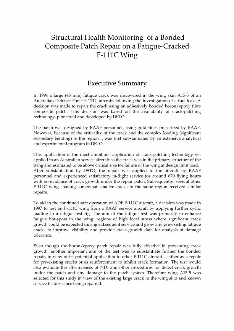
Executive Summary In 1994 a large (48 mm) fatigue crack was discovered in the wing skin A15-5 of an Australian Defence Force F-111C aircraft, following the investigation of a fuel leak. A decision was made to repair the crack using an adhesively bonded boron/epoxy fibre composite patch. This decision was based on the availability of crack-patching technology, pioneered and developed by DSTO. The patch was designed by RAAF personnel, using guidelines prescribed by RAAF. However, because of the criticality of the crack and the complex loading (significant secondary bending) in the region it was first substantiated by an extensive analytical and experimental program in DSTO. This application is the most ambitious application of crack-patching technology yet applied to an Australian service aircraft as the crack was in the primary structure of the wing and estimated to be above critical size for failure of the wing at design limit load. After substantiation by DSTO, the repair was applied to the aircraft by RAAF personnel and experienced satisfactory in-flight service for around 670 flying hours with no evidence of crack growth under the repair patch. Subsequently, several other F-111C wings having somewhat smaller cracks in the same region received similar repairs. To aid in the continued safe operation of ADF F-111C aircraft, a decision was made in 1997 to test an F-111C wing from a RAAF service aircraft by applying further cyclic loading in a fatigue test rig. The aim of the fatigue test was primarily to enhance fatigue hot-spots in the wing: regions of high local stress where significant crack growth could be expected during subsequent service and grow any pre-existing fatigue cracks to improve visibility and provide crack-growth data for analysis of damage tolerance. Even though the boron/epoxy patch repair was fully effective in preventing crack growth, another important aim of the test was to substantiate further the bonded repair, in view of its potential application to other F-111C aircraft � either as a repair for pre-existing cracks or as reinforcement to inhibit crack formation. The test would also evaluate the effectiveness of NDI and other procedures for detect crack growth under the patch and any damage to the patch system. Therefore wing A15-5 was selected for this study in view of the existing large crack in the wing skin and known service history since being repaired.
Clearly, the performance of the patch and the ability of the various monitoring techniques to assess its integrity are of considerable interest, both for the F-111C wing repair and future critical applications of the crack-patching technology: Two monitoring approaches were made using: a) standard non-destructive inspection (NDI) techniques made on the crack and patch and b) a structural-health monitoring (SHM) approach, based on strain measurements, to monitor continuously load transfer into the patch; SHM was used only during the fatigue test. The report describes a) the comparison of NDI indications with the fractographic studies on the crack after the tear down and b) the comparison of the NDI and SHM indications with bond-strength measurements on the patch system, used for validation. Both ultrasonic NDI and SHM based on a strain-gauge technique were very successful in detecting disbonding of the patch which occurred in some localised regions, without compromising the performance of the patch in preventing growth of the patched crack. Whilst there is little doubt that eddy-current NDI is capable of detecting the growth of the patched crack, there were some difficulties in reconciling the NDI and fractographic observations just prior to failure of the wing in the fatigue test. For the patch system, based on the use of the bond-strength test as a destructive calibration procedure, it is concluded that both the NDI and the strain-based SHM technique are effective and can be used with confidence to detect disbonds. However, several significant improvements, discussed in the report, will be required to make the SHM procedure suitable for in-flight application. Future, developments in strain sensors (e.g. optical fibres), power harvesting and wireless communications could make this approach to SHM more robust and reliable. In general, SHM will be cost-effective (and indeed only required) for demanding applications where NDI cannot be easily applied, for example for patch repairs to deeply hidden structure or for particularly critical repairs or where the required frequency of inspection is not feasible. However, the reliability and probability of detection (POD) of the in-flight SHM system will have to be demonstrated to ensure it meets the appropriate airworthiness standards. Importantly SHM must be considered as a confidence increasing back-up to a well planned repair development program, not as an alternative.
Authors
Dr Alan Baker Air Vehicles Division Dr Alan Baker prior to retiring from DSTO was Research Leader Aircraft Materials. On retiring in 2003 he was given the honorary title of Emeritus Research Leader Aircraft Composite Materials. He continues to participate in DSTO research in his specialist field through his current position as Program Leader in the CRC for Advanced Composite Materials.
____________________ ________________________________________________
Contents
1. INTRODUCTION ............................................................................................................... 1
2. BACKGROUND .................................................................................................................. 2 2.1 Wing Crack................................................................................................................. 2 2.2 Choice of Repair Approach..................................................................................... 3 2.3 Repair Design ............................................................................................................ 4 2.4 Repair Design Substantiation ................................................................................ 5
3. PATCH MANUFACTURE AND APPLICATION TO WING SKIN......................... 6
4. FLIGHT HISTORY.............................................................................................................. 8 4.1 NDI of the Patched Wing in Service ..................................................................... 9
5. FULL-SCALE FATIGUE TEST........................................................................................ 10 5.1 Patched Crack NDI and Fractography ................................................................ 12 5.2 Patch Disbond NDI ................................................................................................ 13 5.3 Structural Health Monitoring of the Patch during the Fatigue Test ............. 16
5.3.1 Patch Strain-Gauge Readings Block 2 to 10 at load-line 27 ............... 21 5.3.2 Patch Strain-Gauge Readings Block 12 to 16 load-line 27.................. 22
6. EVALUATION OF RESIDUAL PATCH/ SKIN BOND STRENGTH..................... 28 6.1 Experimental Procedure......................................................................................... 28 6.2 Discussion of Results ............................................................................................. 29
6.2.1 Bond Strengths and Failure Modes....................................................... 29
6.2.2 Comparison of NDI and SHM with Bond Strength Measurements 33
7. DISCUSSION..................................................................................................................... 34
8. CONCLUSIONS ................................................................................................................ 36
APPENDIX 1: ...................................................................................................................... 39 A 1 Examination of the Crack Under Patch in Wing A15-5 ........... 39

9. ACKNOWLEDGEMENTS............................................................................................... 43
DSTO-RR-0335
1
1. Introduction
In February 1994 a large fatigue crack in the wing skin of A15-5 of an Australian Defence Force F-111C was repaired using an adhesively bonded boron/epoxy fibre composite patch. The decision to adopt this repair approach was based on the availability of crack-patching technology, pioneered and developed by DSTO [1,2] over more than 30 years and successfully used to repair many ADF aircraft.
This application is the most ambitious application of crack-patching technology yet applied to an Australian service (and possibly any other) aircraft. This is because the crack was in the primary structure of the wing and above critical size for failure of the wing at design limit load.
The satisfactory RAAF service experience and the subsequent DSTO follow-up activities related to this repair constitute an extremely valuable case history, part of which is captured in this report. However, the main focus of the report is the assessment of the effectiveness of conventional non-destructive inspection (NDI) and Structural Health Monitoring (SHM) to monitor the in-service health of the repair patch.
The patch was designed by RAAF personnel, using guidelines prescribed by RAAF [3] based on DSTO technology. However, because of the criticality of the crack and the complex loading (significant secondary bending) in the region the repair was first substantiated by an extensive analytical and experimental program in DSTO.
After substantiation, the repair was applied to the aircraft by RAAF personnel and experienced satisfactory in-flight service for over three years with no evidence of crack growth under the repair patch. Subsequently, several other F-111 wings having somewhat smaller cracks in the same region received similar repairs.
To aid in the continued safe operation of ADF F-111 aircraft, a decision was made in 1997 to test an F-111 wing retired from a RAAF service aircraft by applying further cyclic loading in a fatigue test rig. The aim of the wing-damage enhancement test [4] (subsequently called the fatigue test), commenced in April 2000, was primarily to �enhance� fatigue hot-spots in the wing - regions of high local stress where significant crack growth could be expected during subsequent service, by growing any pre-existing fatigue cracks to improve visibility. A secondary the aim was to provide crack-growth data for these cracks to allow analysis of damage tolerance.
Even though the boron/epoxy patch repair had proven to be fully effective in preventing crack growth, another important aim of the test was to substantiate further the bonded repair, in view of its potential application to other F-111 (and indeed other ADF) aircraft -either as a repair for pre-existing cracks or as reinforcement to inhibit crack formation. The test would also evaluate the effectiveness of conventional NDI and other procedures for detecting crack growth under the patch and any damage to the patch system. Therefore, wing A15-5 was selected for this study in view of the existing large crack in the wing skin and known service history since being repaired.
DSTO-RR-0335
2
Clearly, the performance of the patch and the ability of the various monitoring techniques to assess its performance are of considerable interest, both for the F-111 wing repair and future critical applications of the crack-patching technology:
Three monitoring approaches were taken: a) standard NDI eddy-current for the crack and b) ultrasonic NDI for the patch - both NDI techniques were used during service and later in the fatigue test and c) SHM for the patch based on strain measurements, using resistance strain-gauges, on the patch and wing skin during the fatigue test.
The report discusses the performance of the patch in inhibiting growth of the patched crack and the associated NDI and then focuses on the NDI and SHM indications on the patch system and their comparison with bond-strength measurements made on the patch at the end of the fatigue test.
Before describing this work, some background is provided on the cracking problem and the design and substantiation of the repair and the subsequent application of the repair to wing.
2. Background
2.1 Wing Crack
The fatigue crack was discovered in the region of the Forward Auxiliary Spar Station (FASS) 281 in the lower wing skin A15-5 of aircraft A8-145 during a routine visual inspection. The wing skin material is aluminium alloy 2025-T851, ~ 4 mm thick in the region of concern.
The first visual indication of the crack was fuel seepage around the crack site. A more detailed follow-up NDI inspection of this region revealed a through-thickness crack, 48 mm long tip-to-tip.
Fracture mechanics calculations for this alloy (using a handbook value of 46 MPa m as the effective fracture toughness for this thickness of aluminium alloy) indicated that the residual strength had been degraded to 168 MPa, which is considerably less than the design ultimate stress of 358 MPa and even more critically the design limit stress of 238 MPa specified for this region of the wing. By definition, the design limit stress is expected to be encountered at least once in the life of the aircraft. Generally, design standards call for a residual strength capability of 1.2 times the design limit stress.
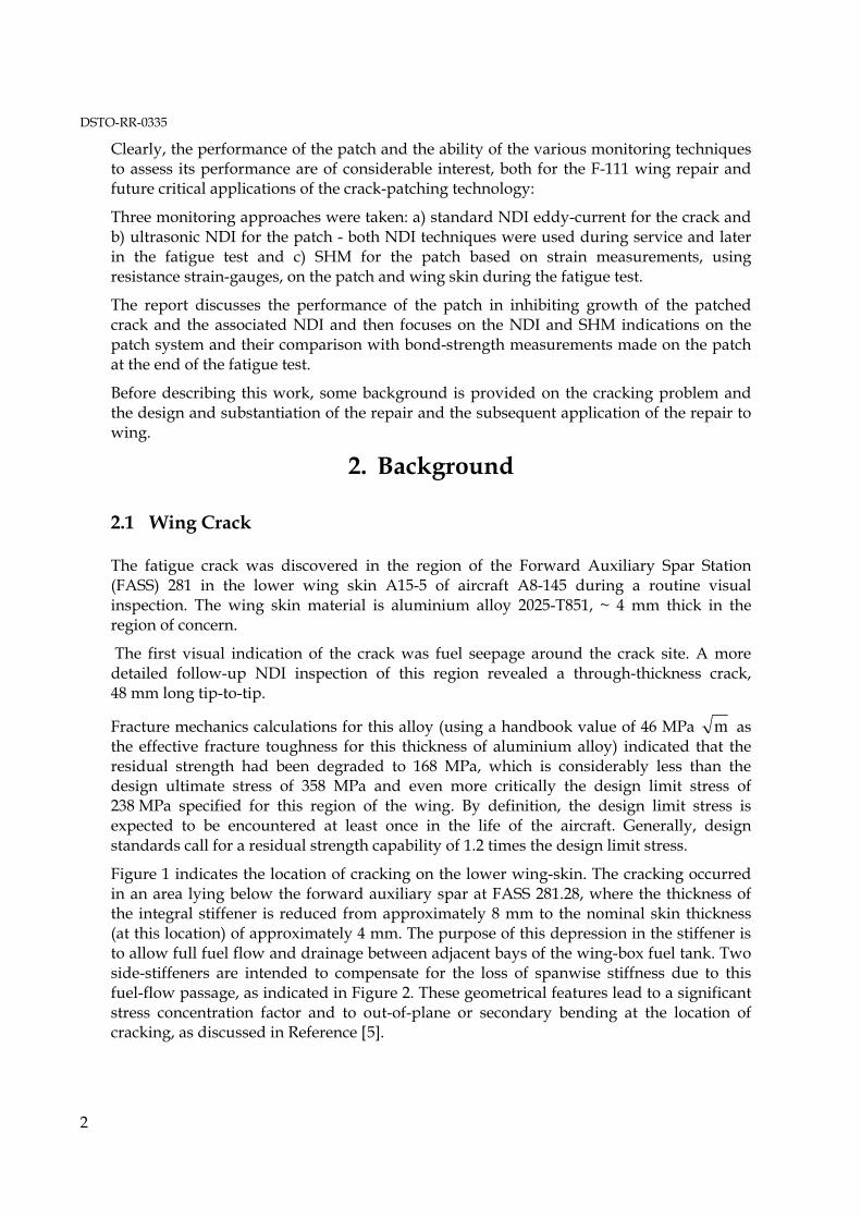
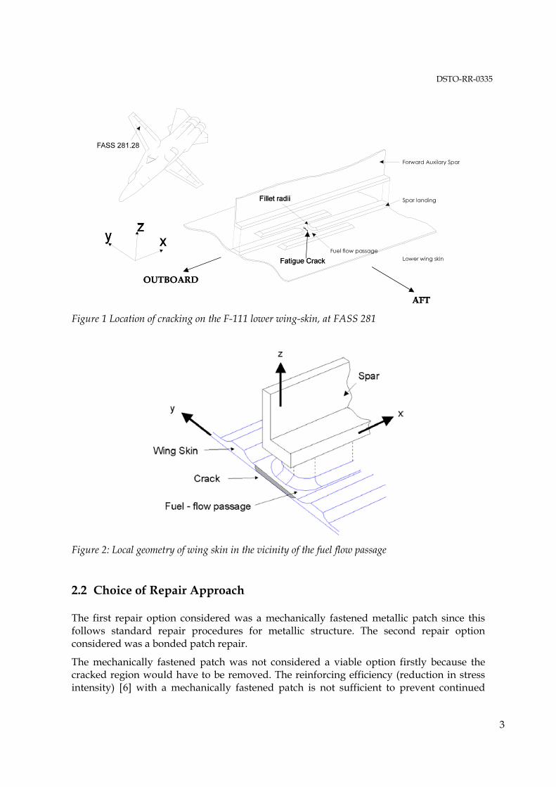
Figure 1 indicates the location of cracking on the lower wing-skin. The cracking occurred in an area lying below the forward auxiliary spar at FASS 281.28, where the thickness of the integral stiffener is reduced from approximately 8 mm to the nominal skin thickness (at this location) of approximately 4 mm. The purpose of this depression in the stiffener is to allow full fuel flow and drainage between adjacent bays of the wing-box fuel tank. Two side-stiffeners are intended to compensate for the loss of spanwise stiffness due to this fuel-flow passage, as indicated in Figure 2. These geometrical features lead to a significant stress concentration factor and to out-of-plane or secondary bending at the location of cracking, as discussed in Reference [5].
DSTO-RR-0335
3
Figure 1 Location of cracking on the F-111 lower wing-skin, at FASS 281
Figure 2: Local geometry of wing skin in the vicinity of the fuel flow passage
2.2 Choice of Repair Approach
The first repair option considered was a mechanically fastened metallic patch since this follows standard repair procedures for metallic structure. The second repair option considered was a bonded patch repair.
The mechanically fastened patch was not considered a viable option firstly because the cracked region would have to be removed. The reinforcing efficiency (reduction in stress intensity) [6] with a mechanically fastened patch is not sufficient to prevent continued
DSTO-RR-0335
4
crack growth. Crack removal was considered infeasible because of the presence of stiffeners in this area. Secondly the introduction of new fastener holes in the cracked region was considered to be a high risk option because of the introduction of new stress concentrators into this highly stressed region - with the consequential danger of further cracking.
The advantages of composite bonded repairs over conventional mechanical repairs are discussed in References [1 and 6]. For the F-111 application the main advantages are a) no fastener holes required and b) no requirement to excise the crack as reinforcing efficiency with bonded reinforcements is high. The conclusion, based on these and other considerations, was that the only viable alternative to a bonded repair would be to scrap the wing.
Boron-fibre/epoxy was chosen over carbon-fibre/epoxy the other high-performance composite candidate for the patch material for several reasons, including:
(i) Higher stiffness which would minimise the aerodynamic profile of the patch;
(ii) Lower electrical conductivity facilitates eddy-current NDI of the crack through the patch and avoids potential galvanic corrosion problems, that are a concern with carbon/epoxy composites; and
(iii) Previous successful applications to repair fatigue cracks in ADF aircraft.
The 120°C curing epoxy-nitrile film adhesive Cytec FM73, was chosen for bonding the patch to the wing skin, based on DSTO�s/RAAF�s successful and extensive experience when using this adhesive for previous bonded repairs.
FM73 provides excellent mechanical properties up to 80°C; however, above this temperature strength falls rapidly [7]. Even though the nominal design operating temperature of the wing (based on the estimated stagnation temperature) is well above this temperature, in-flight measurements conducted by RAAF on an F-111 wing (using thermal paint) indicated that the temperature in the region of the crack to be repaired rarely exceeded 80 ° C.
2.3 Repair Design
There are two issues which make this repair particularly challenging:
Firstly, since the crack had reduced the residual strength of the wing below the specified Design Limit Stress of 238 MPa the continued operation following repair raised safety-of-flight concerns, therefore, certification was a key issue.
Secondly, the local geometry of the wing skin at the site of cracking gives rise to a significant stress concentration resulting from secondary bending in the wing skin � secondary bending of this magnitude had not been encountered in previous Australian applications of bonded repairs. However, the repair was designed using the RAAF Engineering Standard [3], which makes no allowance for the secondary bending.
In the design of the patch the principal load direction for the lower wing skin was assumed to be parallel to the structural axis of the wing box (locally perpendicular to the
DSTO-RR-0335
5
crack direction). Consequently, the majority of the boron fibres were aligned to this axis. The in-plane shear stress in this region was unknown; however, it is known that the shear stress is typically around 5 - 10 per cent of the tensile stress. Therefore, to account for shear stress, the patch layup included a few 45 ° cross-piles. These plies were also seen as aiding in the restoration of torsional rigidity of the wing. To facilitate the transfer of load into the patch over the crack (crack-bridging) unidirectional plies were located adjacent to the bonding surface and the layup was symmetrical to minimise distortion. Thus the final boron/epoxy layup was (02,±45,03)s.
The ends of the patch were stepped internally (tapered with the longest plies on the outside of the patch) to minimise peel and shear stresses. The taper rate chosen of around 3 mm per ply was based on previous studies on the tapering required to avoid fatigue failure in the adhesive system from the ends of the joint; see for example Reference [8].
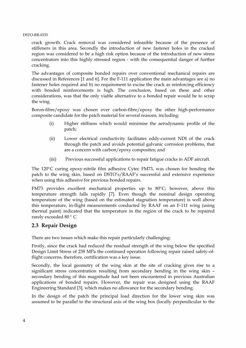
Figure 3 shows schematically the location of the repair patch (looking down through wing skin) and its approximate size in relation to the wing.
Figure 3: Location of cracking on the F-111 lower wing-skin, at FASS 281, showing the outline of the repair patch on the outside surface, which is made of 14 ply boron/epoxy (02, ± 45, 03) size 500 mm spanwise × 350 mm chordwise.
2.4 Repair Design Substantiation
The principal requirements of the substantiation study were to:
1. Validate the analytical formulae used for the repair design by an independent method and to establish if the lack of allowance for secondary bending would invalidate the design.
2. Verify through representative article testing, that the structural integrity of the repaired structure has been restored to the level specified for the original certification of the aircraft, with respect to: (a) static residual strength, (b) durability and damage tolerance, accounting for environmental effects and for possible detrimental effects of the repair on the structural integrity of the surrounding structure. However, the influence of representative damage to the patch was not considered in this analysis.
DSTO-RR-0335
6
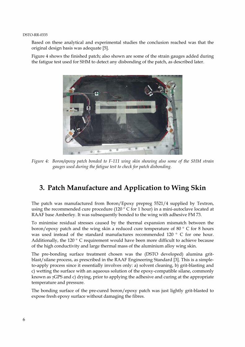
Based on these analytical and experimental studies the conclusion reached was that the original design basis was adequate [5].
Figure 4 shows the finished patch; also shown are some of the strain gauges added during the fatigue test used for SHM to detect any disbonding of the patch, as described later.
Figure 4: Boron/epoxy patch bonded to F-111 wing skin showing also some of the SHM strain gauges used during the fatigue test to check for patch disbonding.
3. Patch Manufacture and Application to Wing Skin
The patch was manufactured from Boron/Epoxy prepreg 5521/4 supplied by Textron, using the recommended cure procedure (120 º C for 1 hour) in a mini-autoclave located at RAAF base Amberley. It was subsequently bonded to the wing with adhesive FM 73.
To minimise residual stresses caused by the thermal expansion mismatch between the boron/epoxy patch and the wing skin a reduced cure temperature of 80 ° C for 8 hours was used instead of the standard manufactures recommended 120 ° C for one hour. Additionally, the 120 ° C requirement would have been more difficult to achieve because of the high conductivity and large thermal mass of the aluminium alloy wing skin.
The pre-bonding surface treatment chosen was the (DSTO developed) alumina grit-blast/silane process, as prescribed in the RAAF Engineering Standard [3]. This is a simple-to-apply process since it essentially involves only: a) solvent cleaning, b) grit-blasting and c) wetting the surface with an aqueous solution of the epoxy-compatible silane, commonly known as γGPS and c) drying, prior to applying the adhesive and curing at the appropriate temperature and pressure.
The bonding surface of the pre-cured boron/epoxy patch was just lightly grit-blasted to expose fresh epoxy surface without damaging the fibres.
DSTO-RR-0335
7
DSTO studies [9] showed that although the grit/blast silane process promotes good environmental durability of the adhesive bond, durability is further enhanced by applying an appropriate bond primer prior to final bonding.
However, for several practical reasons, including perceived difficulties with process control of primer thickness and possible OH&S problems, a decision was made by RAAF not to use the primer (despite strong recommendations for its use from DSTO); as discussed later, use of the primer would have markedly improved bond durability and, possibly, bond strength and fatigue resistance.
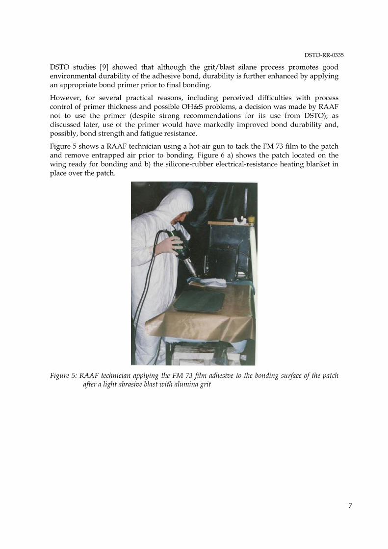
Figure 5 shows a RAAF technician using a hot-air gun to tack the FM 73 film to the patch and remove entrapped air prior to bonding. Figure 6 a) shows the patch located on the wing ready for bonding and b) the silicone-rubber electrical-resistance heating blanket in place over the patch.
Figure 5: RAAF technician applying the FM 73 film adhesive to the bonding surface of the patch after a light abrasive blast with alumina grit
DSTO-RR-0335
8
a)
b)
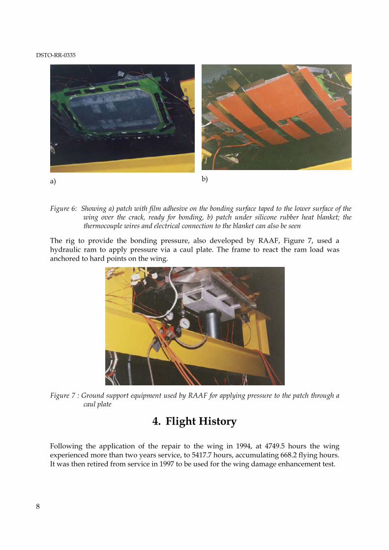
Figure 6: Showing a) patch with film adhesive on the bonding surface taped to the lower surface of the wing over the crack, ready for bonding, b) patch under silicone rubber heat blanket; the thermocouple wires and electrical connection to the blanket can also be seen
The rig to provide the bonding pressure, also developed by RAAF, Figure 7, used a hydraulic ram to apply pressure via a caul plate. The frame to react the ram load was anchored to hard points on the wing.
Figure 7 : Ground support equipment used by RAAF for applying pressure to the patch through a caul plate
4. Flight History
Following the application of the repair to the wing in 1994, at 4749.5 hours the wing experienced more than two years service, to 5417.7 hours, accumulating 668.2 flying hours. It was then retired from service in 1997 to be used for the wing damage enhancement test.
DSTO-RR-0335
9
During service the patch system was inspected regularly (nominally every 100 hours) for evidence of disbonding of the patch or crack growth under the patch.
4.1 NDI of the Patched Wing in Service
RAAF Non-Destructive Inspection Standard 6.19 Part 1 and Part 2 were developed to detect the crack under the patch and disbonding of the patch. Part 1 of the standard is an eddy-current procedure using a Nortec 2000 instrument for assessing the crack; Part 2 is an ultrasonic procedure using a 2100 Bondascope for assessing disbonding.
Up to withdrawal of the wing for fatigue testing when the wing had accumulated a total of 668.2 flying hours no crack growth was reported. Actually, although measurements made prior to 5417.7 flying hours indicated no growth, the final inspection at the time the wing was retired, indicated that there may have been some growth of the crack; however, it was finally concluded, after a check inspection at DSTO, that in fact no growth had occurred - consequently the final crack size at commencement of the fatigue test was taken as 47.6 mm.
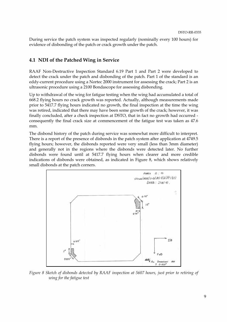
The disbond history of the patch during service was somewhat more difficult to interpret. There is a report of the presence of disbonds in the patch system after application at 4749.5 flying hours; however, the disbonds reported were very small (less than 3mm diameter) and generally not in the regions where the disbonds were detected later. No further disbonds were found until at 5417.7 flying hours when clearer and more credible indications of disbonds were obtained, as indicated in Figure 8, which shows relatively small disbonds at the patch corners.
Figure 8 Sketch of disbonds detected by RAAF inspection at 5607 hours, just prior to retiring of wing for the fatigue test
DSTO-RR-0335
10
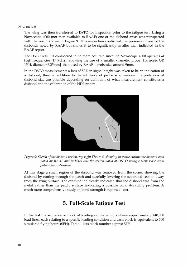
The wing was then transferred to DSTO for inspection prior to the fatigue test. Using a Novascope 4000 (not then available to RAAF) one of the disbond areas was reinspected with the result shown in Figure 9. This inspection confirmed the presence of one of the disbonds noted by RAAF but shows it to be significantly smaller than indicated in the RAAF report.
The DSTO result is considered to be more accurate since the Novascope 4000 operates at high frequencies (15 MHz), allowing the use of a smaller diameter probe [Harisonic GR 1504, diameter 6.35mm] than used by RAAF � probe size around 9mm.
In the DSTO measurements a loss of 50% in signal height was taken to be an indication of a disbond; thus, in addition to the influence of probe size, various interpretations of disbond size are possible depending on definition of what measurement constitutes a disbond and the calibration of the NDI system.
Figure 9: Sketch of the disbond region, top right Figure 8, showing in white outline the disbond area noted by RAAF and in black line the region noted at DSTO using a Novascope 4000 pulse echo instrument
At this stage a small region of the disbond was removed from the corner showing the disbond by cutting through the patch and carefully levering the separated section away from the wing surface. The examination clearly indicated that the disbond was from the metal, rather than the patch, surface, indicating a possible bond durability problem. A much more comprehensive study on bond strength is reported later.
5. Full-Scale Fatigue Test
In the test the sequence or block of loading on the wing contains approximately 140,000 load-lines, each relating to a specific loading condition and each block is equivalent to 500 simulated flying hours (SFH). Table 1 lists block number against SFH.
DSTO-RR-0335
11
Table 1 Blocks of simulated flights with equivalent simulated flying hours
Block SFH Block SFH 1 5918 10 10418 2 6418 11 10918 3 6918 12 11418 4 7418 13 11918 5 7918 14 12418 6 8418 15 12918 7 8918 16 13418 8 9418 17 13918 9 9918
In addition to the fatigue loads, loads representing the cold-proof test were also applied; the cold proof test (CPLT) is a proof load, equivalent to a 7.3 g manoeuvre, generally applied to service aircraft at a low temperature of - 40°C. This test is used as a safety check to screen the fracture sensitive D6AC steel components in the wing for small cracks not easily detected by NDI. However, in the fatigue test the CPLT loads were applied at ambient temperature.
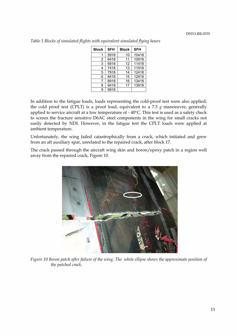
Unfortunately, the wing failed catastrophically from a crack, which initiated and grew from an aft auxiliary spar, unrelated to the repaired crack, after block 17.
The crack passed through the aircraft wing skin and boron/epoxy patch in a region well away from the repaired crack, Figure 10.
Figure 10 Boron patch after failure of the wing. The white ellipse shows the approximate position of the patched crack.
DSTO-RR-0335
12
5.1 Patched Crack NDI and Fractography
The patched crack was monitored by NDI during the fatigue test initially every 2000 SFH, using the RAAF Non-Destructive Inspection Standard 6.19. The conclusion was that the crack size was around 48 mm ±2 mm and that zero crack growth was detected up to 13500 hours.
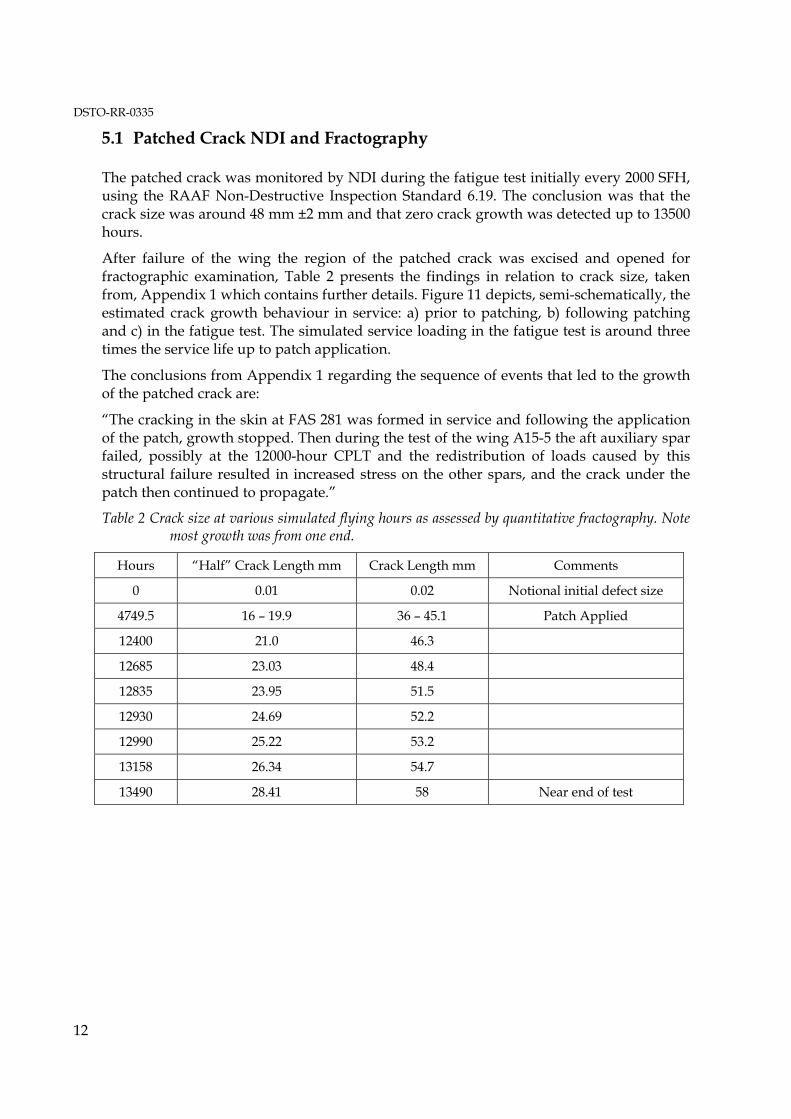
After failure of the wing the region of the patched crack was excised and opened for fractographic examination, Table 2 presents the findings in relation to crack size, taken from, Appendix 1 which contains further details. Figure 11 depicts, semi-schematically, the estimated crack growth behaviour in service: a) prior to patching, b) following patching and c) in the fatigue test. The simulated service loading in the fatigue test is around three times the service life up to patch application.
The conclusions from Appendix 1 regarding the sequence of events that led to the growth of the patched crack are:
�The cracking in the skin at FAS 281 was formed in service and following the application of the patch, growth stopped. Then during the test of the wing A15-5 the aft auxiliary spar failed, possibly at the 12000-hour CPLT and the redistribution of loads caused by this structural failure resulted in increased stress on the other spars, and the crack under the patch then continued to propagate.�
Table 2 Crack size at various simulated flying hours as assessed by quantitative fractography. Note most growth was from one end.
Hours �Half� Crack Length mm Crack Length mm Comments
0 0.01 0.02 Notional initial defect size
4749.5 16 � 19.9 36 � 45.1 Patch Applied
12400 21.0 46.3
12685 23.03 48.4
12835 23.95 51.5
12930 24.69 52.2
12990 25.22 53.2
13158 26.34 54.7
13490 28.41 58 Near end of test
DSTO-RR-0335
13
Figure 11 Plot of crack size over the life of the wing measured from fractographic analysis of the patched crack region, derived from Appendix 1
The fractographic observations indicate that the initial full length of the crack was between 36 mm (min) to 45.1 mm (max) with zero to negligible growth up to around 12000 hours. There was considerable uncertainly from the fractographic study at this stage, presumably because of the state of the fracture surface. Then from 12400 hours to 13507 hours the crack propagated to a length of 58 mm at which time final wing failure occurred.
The maximum initial length of 45.1 compares quite well with the NDI determination of ~ 48 mm ±2 mm. However, the fact that NDI did not detect growth after 12400 hours is an issue of some concern.
Follow-up discussions were held with the DSTO NDI expert involved in the fatigue test who expressed confidence, based on previous experience with patched cracks and experience gained in this fatigue test, that the eddy-current NDI would have detected any significant crack growth under the patch.
Thus the implication is that the growth occurred after the last NDI, well before catastrophic failure of the wing. Unfortunately, this conclusion does not fit in with the reported last time of NDI so this key issue cannot be resolved.
5.2 Patch Disbond NDI
The patch was monitored with ultrasonic NDI following the RAAF Non-Destructive Inspection Standard 6.19 Part 2. At 10525 SFH indications were obtained from the NDI that some of the pre-existing patch disbonds had grown and new disbonds had appeared;
DSTO-RR-0335
14
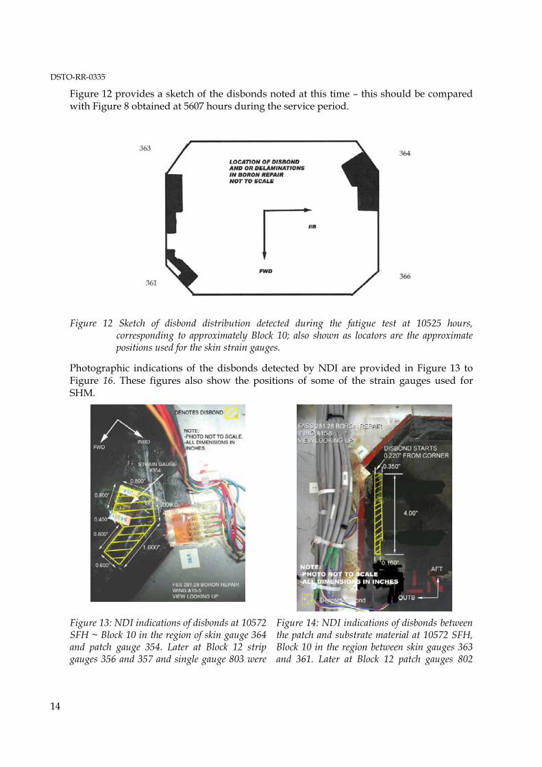
Figure 12 provides a sketch of the disbonds noted at this time � this should be compared with Figure 8 obtained at 5607 hours during the service period.
Figure 12 Sketch of disbond distribution detected during the fatigue test at 10525 hours, corresponding to approximately Block 10; also shown as locators are the approximate positions used for the skin strain gauges.
Photographic indications of the disbonds detected by NDI are provided in Figure 13 to Figure 16. These figures also show the positions of some of the strain gauges used for SHM.
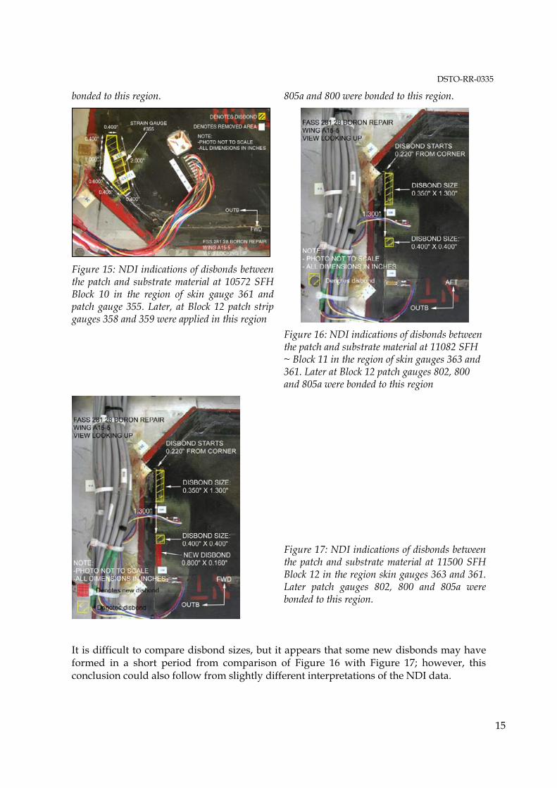
Figure 13: NDI indications of disbonds at 10572 SFH ~ Block 10 in the region of skin gauge 364 and patch gauge 354. Later at Block 12 strip gauges 356 and 357 and single gauge 803 were
Figure 14: NDI indications of disbonds between the patch and substrate material at 10572 SFH, Block 10 in the region between skin gauges 363 and 361. Later at Block 12 patch gauges 802
DSTO-RR-0335
15
bonded to this region. 805a and 800 were bonded to this region.
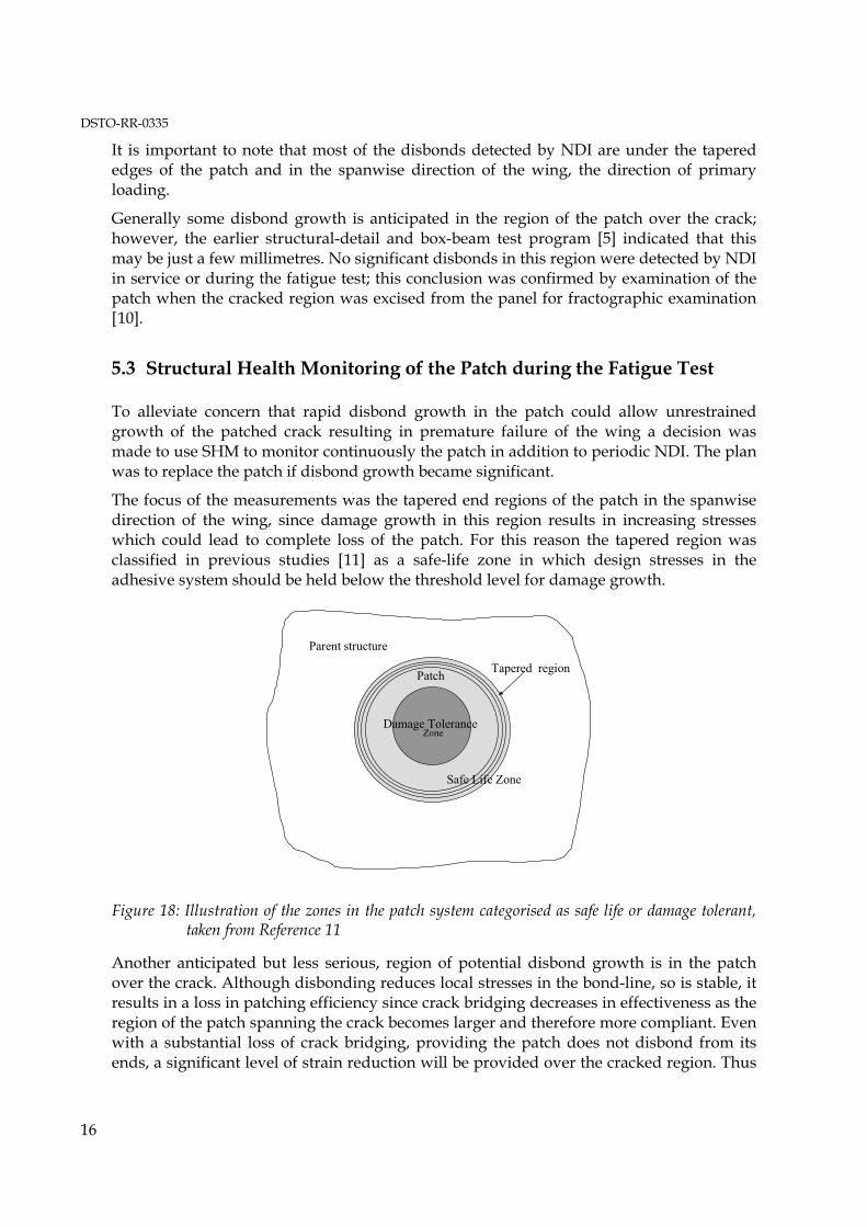
Figure 15: NDI indications of disbonds between the patch and substrate material at 10572 SFH Block 10 in the region of skin gauge 361 and patch gauge 355. Later, at Block 12 patch strip gauges 358 and 359 were applied in this region
Figure 16: NDI indications of disbonds between the patch and substrate material at 11082 SFH ~ Block 11 in the region of skin gauges 363 and 361. Later at Block 12 patch gauges 802, 800 and 805a were bonded to this region
Figure 17: NDI indications of disbonds between the patch and substrate material at 11500 SFH Block 12 in the region skin gauges 363 and 361. Later patch gauges 802, 800 and 805a were bonded to this region.
It is difficult to compare disbond sizes, but it appears that some new disbonds may have formed in a short period from comparison of Figure 16 with Figure 17; however, this conclusion could also follow from slightly different interpretations of the NDI data.
DSTO-RR-0335
16
It is important to note that most of the disbonds detected by NDI are under the tapered edges of the patch and in the spanwise direction of the wing, the direction of primary loading.
Generally some disbond growth is anticipated in the region of the patch over the crack; however, the earlier structural-detail and box-beam test program [5] indicated that this may be just a few millimetres. No significant disbonds in this region were detected by NDI in service or during the fatigue test; this conclusion was confirmed by examination of the patch when the cracked region was excised from the panel for fractographic examination [10]. 5.3 Structural Health Monitoring of the Patch during the Fatigue Test
To alleviate concern that rapid disbond growth in the patch could allow unrestrained growth of the patched crack resulting in premature failure of the wing a decision was made to use SHM to monitor continuously the patch in addition to periodic NDI. The plan was to replace the patch if disbond growth became significant.
The focus of the measurements was the tapered end regions of the patch in the spanwise direction of the wing, since damage growth in this region results in increasing stresses which could lead to complete loss of the patch. For this reason the tapered region was classified in previous studies [11] as a safe-life zone in which design stresses in the adhesive system should be held below the threshold level for damage growth.
Safe Life Zone
Damage Tolerance Zone
Tapered region
Parent structure
Patch
Figure 18: Illustration of the zones in the patch system categorised as safe life or damage tolerant, taken from Reference 11
Another anticipated but less serious, region of potential disbond growth is in the patch over the crack. Although disbonding reduces local stresses in the bond-line, so is stable, it results in a loss in patching efficiency since crack bridging decreases in effectiveness as the region of the patch spanning the crack becomes larger and therefore more compliant. Even with a substantial loss of crack bridging, providing the patch does not disbond from its ends, a significant level of strain reduction will be provided over the cracked region. Thus
DSTO-RR-0335
17
this region was previously classified as a damage tolerant zone, so not of prime concern for strain-gauge measurements; Figure 18 depicts these hypothetical regions.
The SHM technique used here, first developed in two previous studies [12,13], is based on strain measurements from resistance strain gauges bonded to the patch and parent structure � the wing skin. The efficiency of load transfer to the patch (through the tapered region) is assessed by comparing the far-field strain in the wing skin with the strain transferred into the patch in a similar stress field. Any continuous reduction in the ratio (patch strain)/(far-field strain) indicates a loss of load transfer in this region which could only be caused by growth of a disbond [11]. As this approach does not require any knowledge of the loading just synchronous measurement of strain in the patch and parent structure it is well suited to in-flight SHM under random loading.
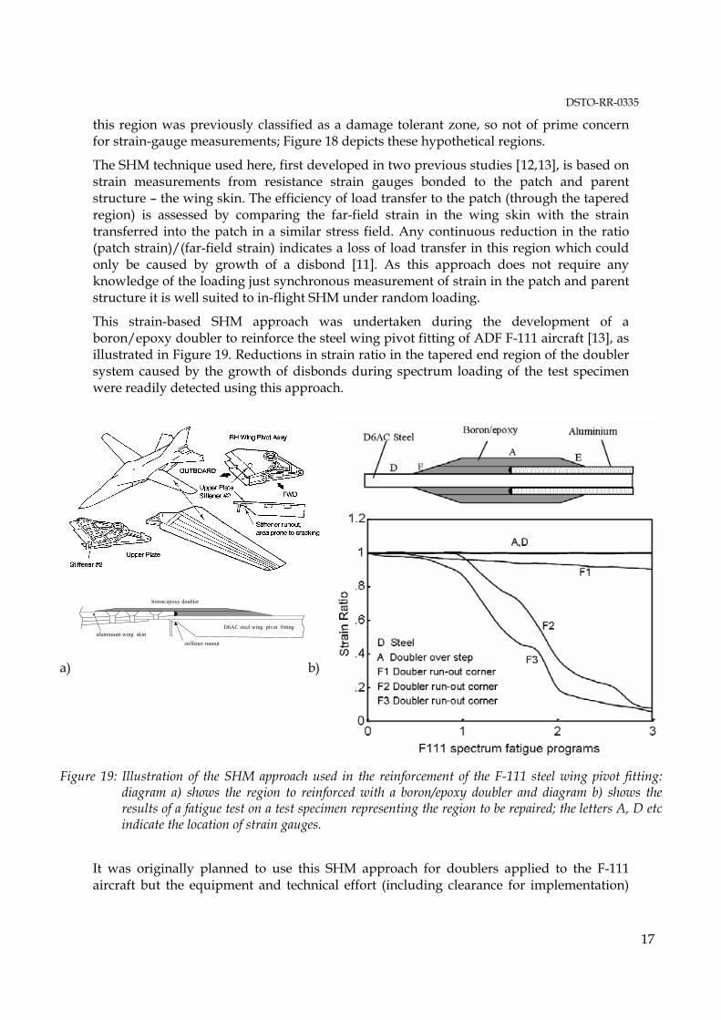
This strain-based SHM approach was undertaken during the development of a boron/epoxy doubler to reinforce the steel wing pivot fitting of ADF F-111 aircraft [13], as illustrated in Figure 19. Reductions in strain ratio in the tapered end region of the doubler system caused by the growth of disbonds during spectrum loading of the test specimen were readily detected using this approach.
boron/epoxy doubler
stiffener runout
D6AC steel wing pivot fittingaluminium wing skin
a) b)
Figure 19: Illustration of the SHM approach used in the reinforcement of the F-111 steel wing pivot fitting: diagram a) shows the region to reinforced with a boron/epoxy doubler and diagram b) shows the results of a fatigue test on a test specimen representing the region to be repaired; the letters A, D etc indicate the location of strain gauges.
It was originally planned to use this SHM approach for doublers applied to the F-111 aircraft but the equipment and technical effort (including clearance for implementation)
DSTO-RR-0335
18
required made this infeasible at the time. However, had this SHM approach been employed the disbonding of the doubler which occurred on some in-service aircraft (caused by fatigue damage in adhesive system) would have been detected very early and without the periodic costly requirement for removal of the fixed fairings covering the doublers.
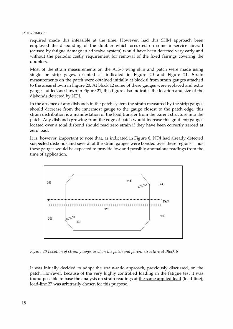
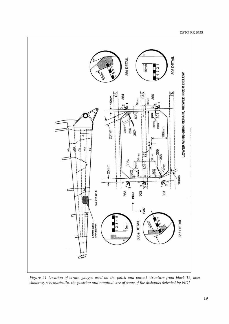
Most of the strain measurements on the A15-5 wing skin and patch were made using single or strip gages, oriented as indicated in Figure 20 and Figure 21. Strain measurements on the patch were obtained initially at block 6 from strain gauges attached to the areas shown in Figure 20. At block 12 some of these gauges were replaced and extra gauges added, as shown in Figure 21; this figure also indicates the location and size of the disbonds detected by NDI.
In the absence of any disbonds in the patch system the strain measured by the strip gauges should decrease from the innermost gauge to the gauge closest to the patch edge; this strain distribution is a manifestation of the load transfer from the parent structure into the patch. Any disbonds growing from the edge of patch would increase this gradient; gauges located over a total disbond should read zero strain if they have been correctly zeroed at zero load.
It is, however, important to note that, as indicated in Figure 8, NDI had already detected suspected disbonds and several of the strain gauges were bonded over these regions. Thus these gauges would be expected to provide low and possibly anomalous readings from the time of application.
Figure 20 Location of strain gauges used on the patch and parent structure at Block 6
It was initially decided to adopt the strain-ratio approach, previously discussed, on the patch. However, because of the very highly controlled loading in the fatigue test it was found possible to base the analysis on strain readings at the same applied load (load-line); load-line 27 was arbitrarily chosen for this purpose.
DSTO-RR-0335
19
Figure 21 Location of strain gauges used on the patch and parent structure from block 12, also showing, schematically, the position and nominal size of some of the disbonds detected by NDI
DSTO-RR-0335
20
In the test there are 140000 load-lines and strain readings on the wing-skin and patch were made for many of these. However, it is assumed (although not checked) that strain readings at other significant load-lines would have led to the same conclusion as was reached based on load-line 27.
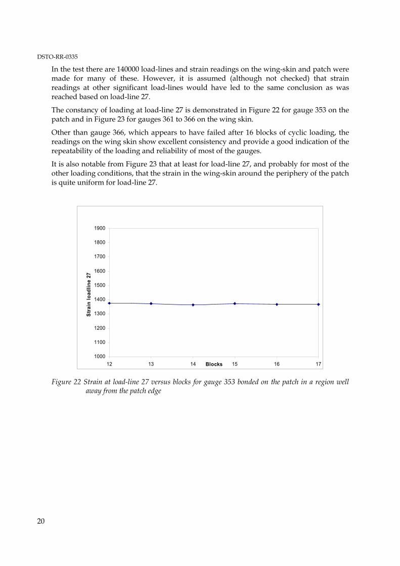
The constancy of loading at load-line 27 is demonstrated in Figure 22 for gauge 353 on the patch and in Figure 23 for gauges 361 to 366 on the wing skin.
Other than gauge 366, which appears to have failed after 16 blocks of cyclic loading, the readings on the wing skin show excellent consistency and provide a good indication of the repeatability of the loading and reliability of most of the gauges.
It is also notable from Figure 23 that at least for load-line 27, and probably for most of the other loading conditions, that the strain in the wing-skin around the periphery of the patch is quite uniform for load-line 27.
1000
1100
1200
1300
1400
1500
1600
1700
1800
1900
12 13 14 15 16 17Blocks
Stra
in lo
adlin
e 27
Figure 22 Strain at load-line 27 versus blocks for gauge 353 bonded on the patch in a region well away from the patch edge
DSTO-RR-0335
21
0
500
1000
1500
2000
2500
3000
3500
13 14 15 16 17
Blocks
Stra
in L
oadl
ine
27
366-1
361-1 362-3 363-3 364-1
Figure 23 Strain at load-line 27 versus blocks for gauges bonded on the wing skin
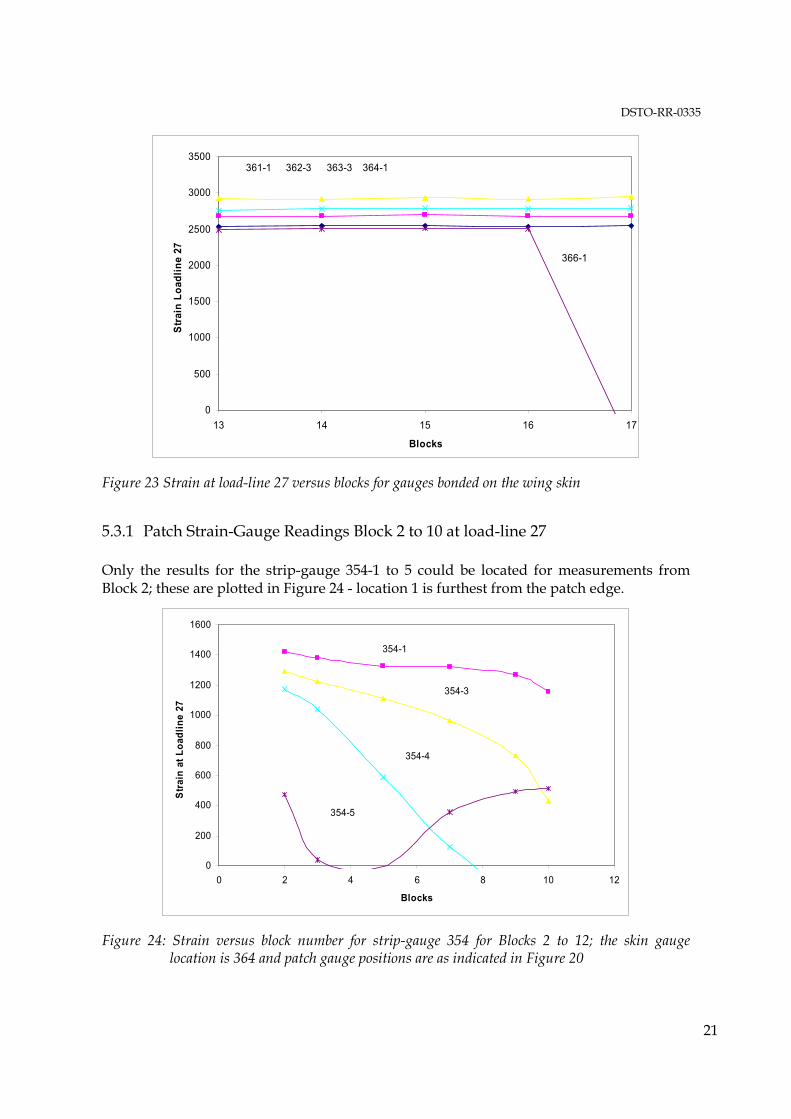
5.3.1 Patch Strain-Gauge Readings Block 2 to 10 at load-line 27
Only the results for the strip-gauge 354-1 to 5 could be located for measurements from Block 2; these are plotted in Figure 24 - location 1 is furthest from the patch edge.
0
200
400
600
800
1000
1200
1400
1600
0 2 4 6 8 10 12
Blocks
Stra
in a
t Loa
dlin
e 27
354-1
354-3
354-4
354-5
Figure 24: Strain versus block number for strip-gauge 354 for Blocks 2 to 12; the skin gauge location is 364 and patch gauge positions are as indicated in Figure 20
DSTO-RR-0335
22
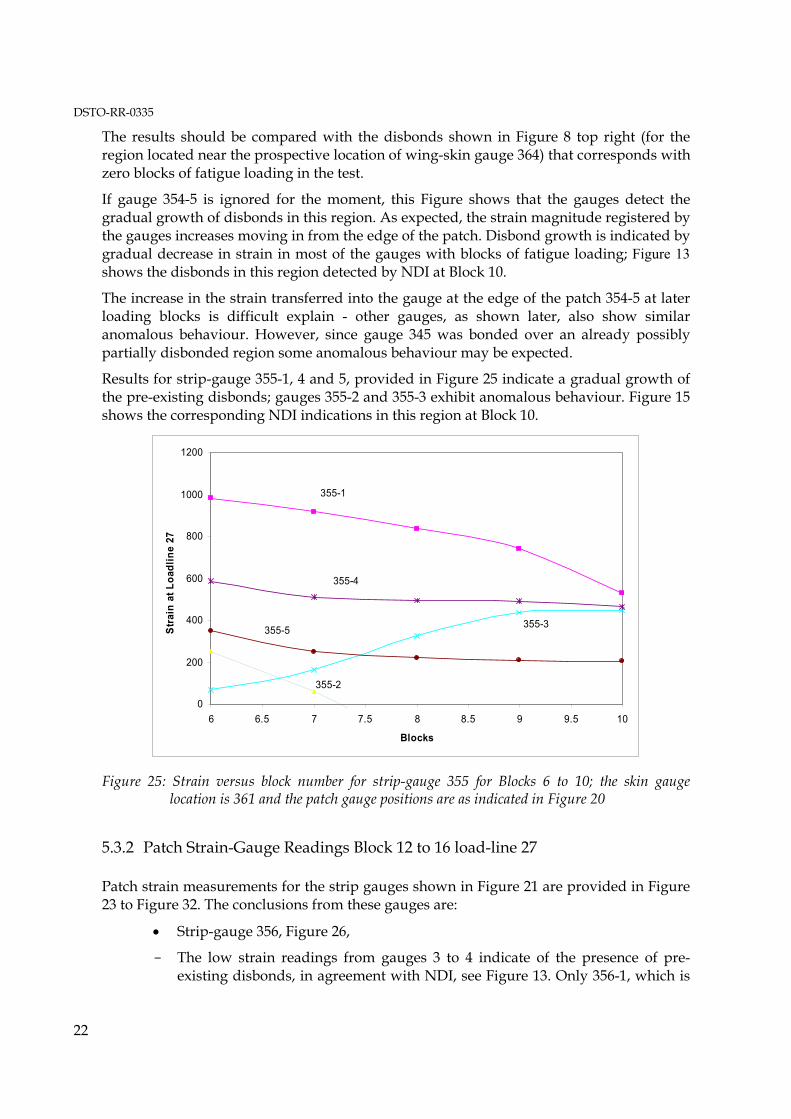
The results should be compared with the disbonds shown in Figure 8 top right (for the region located near the prospective location of wing-skin gauge 364) that corresponds with zero blocks of fatigue loading in the test.
If gauge 354-5 is ignored for the moment, this Figure shows that the gauges detect the gradual growth of disbonds in this region. As expected, the strain magnitude registered by the gauges increases moving in from the edge of the patch. Disbond growth is indicated by gradual decrease in strain in most of the gauges with blocks of fatigue loading; Figure 13 shows the disbonds in this region detected by NDI at Block 10.
The increase in the strain transferred into the gauge at the edge of the patch 354-5 at later loading blocks is difficult explain - other gauges, as shown later, also show similar anomalous behaviour. However, since gauge 345 was bonded over an already possibly partially disbonded region some anomalous behaviour may be expected.
Results for strip-gauge 355-1, 4 and 5, provided in Figure 25 indicate a gradual growth of the pre-existing disbonds; gauges 355-2 and 355-3 exhibit anomalous behaviour. Figure 15 shows the corresponding NDI indications in this region at Block 10.
0
200
400
600
800
1000
1200
6 6.5 7 7.5 8 8.5 9 9.5 10
Blocks
Stra
in a
t Loa
dlin
e 27
355-2
355-1
355-4
355-5 355-3
Figure 25: Strain versus block number for strip-gauge 355 for Blocks 6 to 10; the skin gauge location is 361 and the patch gauge positions are as indicated in Figure 20
5.3.2 Patch Strain-Gauge Readings Block 12 to 16 load-line 27
Patch strain measurements for the strip gauges shown in Figure 21 are provided in Figure 23 to Figure 32. The conclusions from these gauges are:
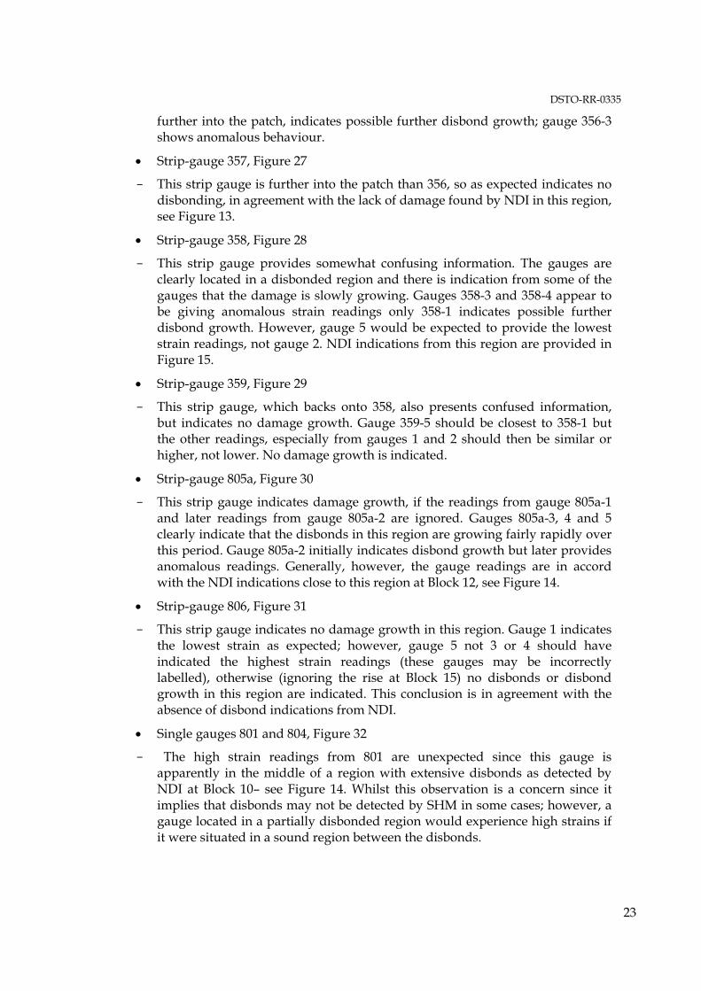
• Strip-gauge 356, Figure 26,
- The low strain readings from gauges 3 to 4 indicate of the presence of pre-existing disbonds, in agreement with NDI, see Figure 13. Only 356-1, which is
DSTO-RR-0335
23
further into the patch, indicates possible further disbond growth; gauge 356-3 shows anomalous behaviour.
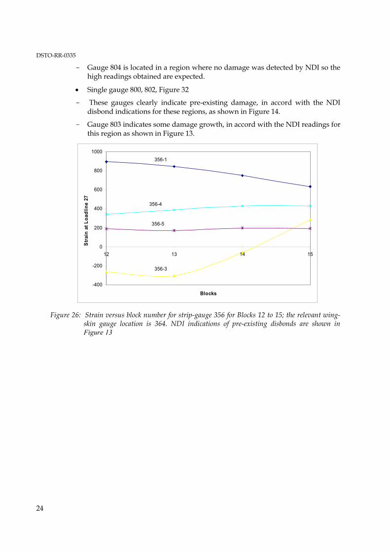
• Strip-gauge 357, Figure 27
- This strip gauge is further into the patch than 356, so as expected indicates no disbonding, in agreement with the lack of damage found by NDI in this region, see Figure 13.
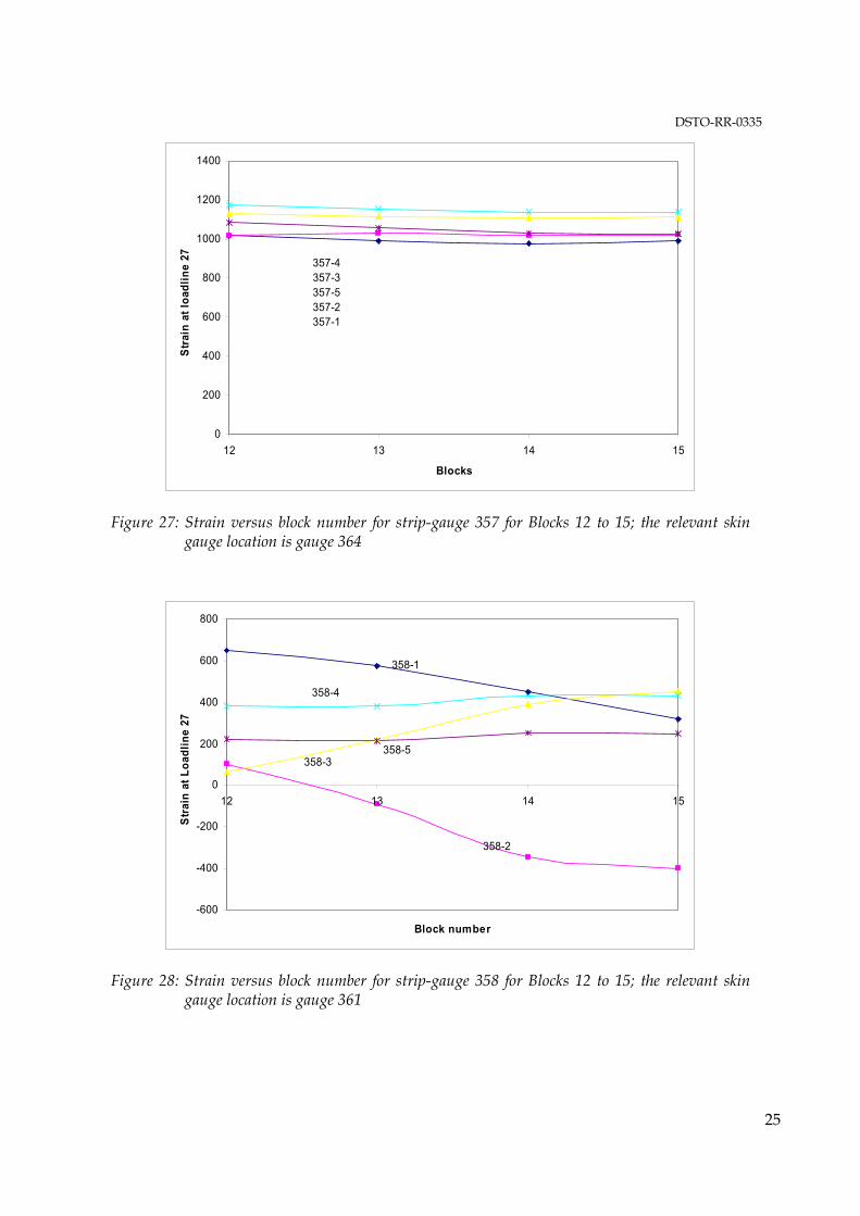
• Strip-gauge 358, Figure 28
- This strip gauge provides somewhat confusing information. The gauges are clearly located in a disbonded region and there is indication from some of the gauges that the damage is slowly growing. Gauges 358-3 and 358-4 appear to be giving anomalous strain readings only 358-1 indicates possible further disbond growth. However, gauge 5 would be expected to provide the lowest strain readings, not gauge 2. NDI indications from this region are provided in Figure 15.
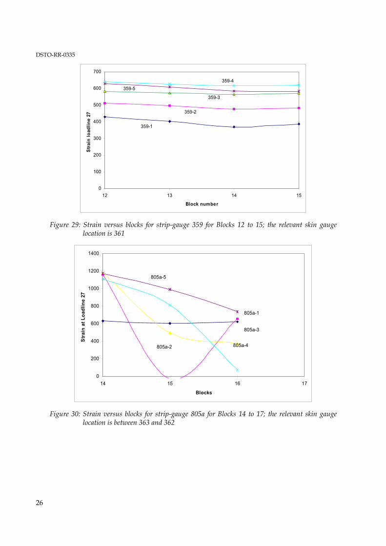
• Strip-gauge 359, Figure 29
- This strip gauge, which backs onto 358, also presents confused information, but indicates no damage growth. Gauge 359-5 should be closest to 358-1 but the other readings, especially from gauges 1 and 2 should then be similar or higher, not lower. No damage growth is indicated.
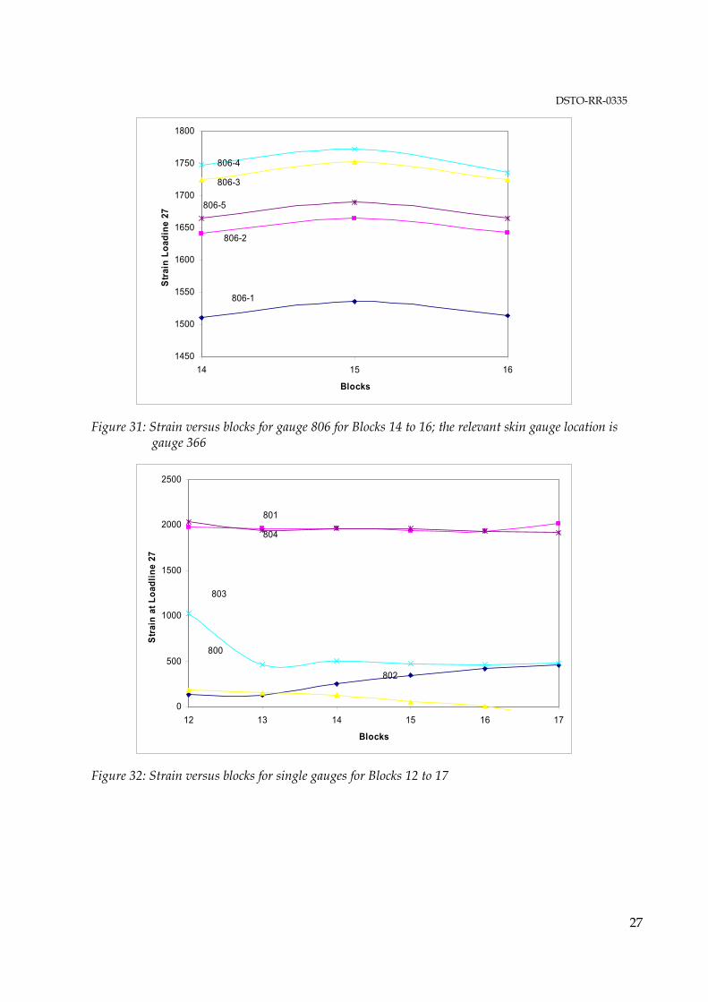
• Strip-gauge 805a, Figure 30
- This strip gauge indicates damage growth, if the readings from gauge 805a-1 and later readings from gauge 805a-2 are ignored. Gauges 805a-3, 4 and 5 clearly indicate that the disbonds in this region are growing fairly rapidly over this period. Gauge 805a-2 initially indicates disbond growth but later provides anomalous readings. Generally, however, the gauge readings are in accord with the NDI indications close to this region at Block 12, see Figure 14.
• Strip-gauge 806, Figure 31
- This strip gauge indicates no damage growth in this region. Gauge 1 indicates the lowest strain as expected; however, gauge 5 not 3 or 4 should have indicated the highest strain readings (these gauges may be incorrectly labelled), otherwise (ignoring the rise at Block 15) no disbonds or disbond growth in this region are indicated. This conclusion is in agreement with the absence of disbond indications from NDI.
• Single gauges 801 and 804, Figure 32
- The high strain readings from 801 are unexpected since this gauge is apparently in the middle of a region with extensive disbonds as detected by NDI at Block 10� see Figure 14. Whilst this observation is a concern since it implies that disbonds may not be detected by SHM in some cases; however, a gauge located in a partially disbonded region would experience high strains if it were situated in a sound region between the disbonds.
DSTO-RR-0335
24
- Gauge 804 is located in a region where no damage was detected by NDI so the high readings obtained are expected.
• Single gauge 800, 802, Figure 32
- These gauges clearly indicate pre-existing damage, in accord with the NDI disbond indications for these regions, as shown in Figure 14.
- Gauge 803 indicates some damage growth, in accord with the NDI readings for this region as shown in Figure 13.
-400
-200
0
200
400
600
800
1000
12 13 14 15
Blocks
Stra
in a
t Loa
dlin
e 27
356-1
356-4
356-5
356-3
Figure 26: Strain versus block number for strip-gauge 356 for Blocks 12 to 15; the relevant wing-skin gauge location is 364. NDI indications of pre-existing disbonds are shown in Figure 13
DSTO-RR-0335
25
0
200
400
600
800
1000
1200
1400
12 13 14 15
Blocks
Stra
in a
t loa
dlin
e 27 357-4
357-3357-5357-2357-1
Figure 27: Strain versus block number for strip-gauge 357 for Blocks 12 to 15; the relevant skin gauge location is gauge 364
-600
-400
-200
0
200
400
600
800
12 13 14 15
Block number
Stra
in a
t Loa
dlin
e 27
358-1
358-4
358-3358-5
358-2
Figure 28: Strain versus block number for strip-gauge 358 for Blocks 12 to 15; the relevant skin gauge location is gauge 361
DSTO-RR-0335
26
0
100
200
300
400
500
600
700
12 13 14 15
Block number
Stra
in lo
adlin
e 27
359-1
359-2
359-3
359-4359-5
Figure 29: Strain versus blocks for strip-gauge 359 for Blocks 12 to 15; the relevant skin gauge location is 361
0
200
400
600
800
1000
1200
1400
14 15 16 17
Blocks
Stra
in a
t Loa
dlin
e 27
805a-5
805a-4
805a-3
805a-1
805a-2
Figure 30: Strain versus blocks for strip-gauge 805a for Blocks 14 to 17; the relevant skin gauge location is between 363 and 362
DSTO-RR-0335
27
1450
1500
1550
1600
1650
1700
1750
1800
14 15 16
Blocks
Stra
in L
oadi
ne 2
7
806-3
806-4
806-5
806-2
806-1
Figure 31: Strain versus blocks for gauge 806 for Blocks 14 to 16; the relevant skin gauge location is gauge 366
0
500
1000
1500
2000
2500
12 13 14 15 16 17
Blocks
Stra
in a
t Loa
dlin
e 27
801
804
800
803
802
Figure 32: Strain versus blocks for single gauges for Blocks 12 to 17
DSTO-RR-0335
28
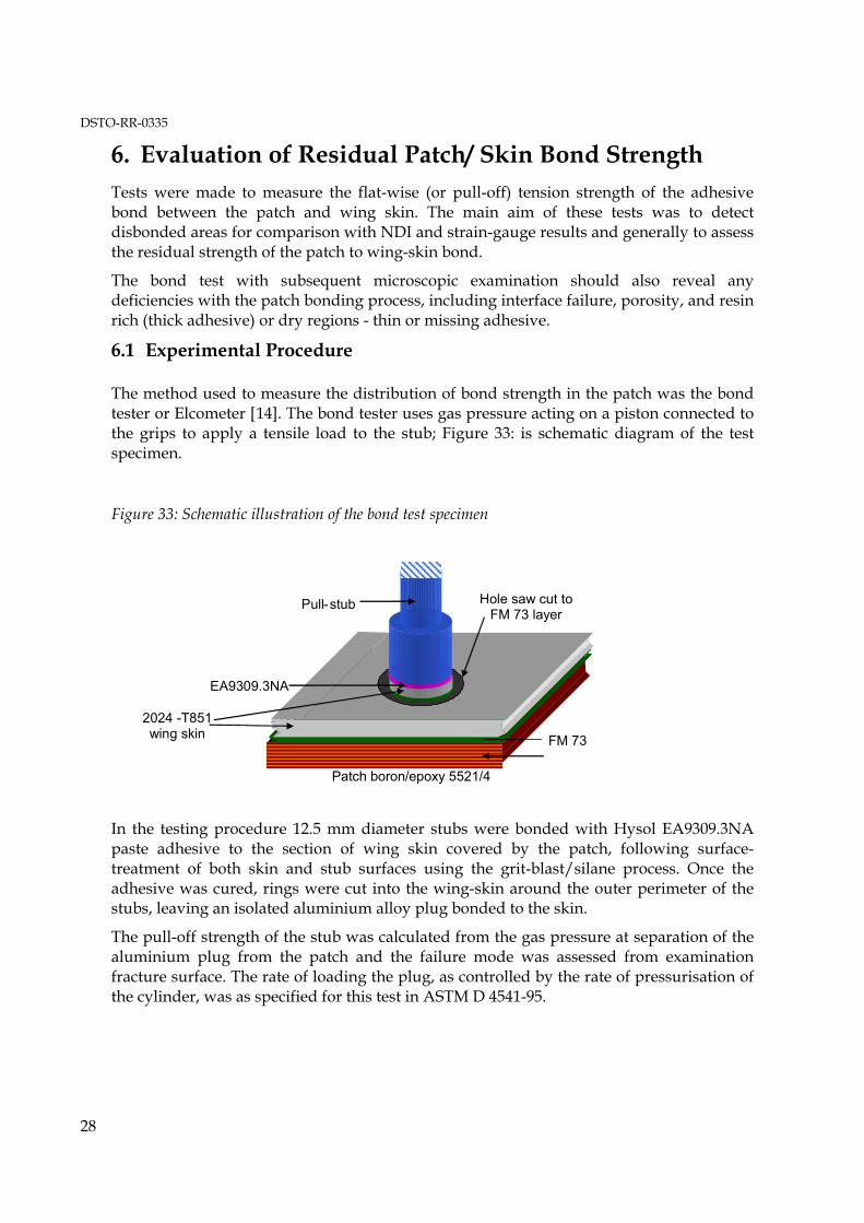
6. Evaluation of Residual Patch/ Skin Bond Strength Tests were made to measure the flat-wise (or pull-off) tension strength of the adhesive bond between the patch and wing skin. The main aim of these tests was to detect disbonded areas for comparison with NDI and strain-gauge results and generally to assess the residual strength of the patch to wing-skin bond.
The bond test with subsequent microscopic examination should also reveal any deficiencies with the patch bonding process, including interface failure, porosity, and resin rich (thick adhesive) or dry regions - thin or missing adhesive.
6.1 Experimental Procedure
The method used to measure the distribution of bond strength in the patch was the bond tester or Elcometer [14]. The bond tester uses gas pressure acting on a piston connected to the grips to apply a tensile load to the stub; Figure 33: is schematic diagram of the test specimen.
Figure 33: Schematic illustration of the bond test specimen
In the testing procedure 12.5 mm diameter stubs were bonded with Hysol EA9309.3NA paste adhesive to the section of wing skin covered by the patch, following surface-treatment of both skin and stub surfaces using the grit-blast/silane process. Once the adhesive was cured, rings were cut into the wing-skin around the outer perimeter of the stubs, leaving an isolated aluminium alloy plug bonded to the skin.
The pull-off strength of the stub was calculated from the gas pressure at separation of the aluminium plug from the patch and the failure mode was assessed from examination fracture surface. The rate of loading the plug, as controlled by the rate of pressurisation of the cylinder, was as specified for this test in ASTM D 4541-95.
Pull -stub
EA9309.3NA
FM 73
Patch boron/epoxy 5521/4
Hole saw cut to FM 73 layer
2024 -T851 wing skin
DSTO-RR-0335
29
6.2 Discussion of Results
6.2.1 Bond Strengths and Failure Modes
Environmental degradation of the adhesive bond would be manifested in the test as low strength and failure at the aluminium alloy surface - termed adhesive failure. Whilst if correctly cleaned and abraded the adhesive bond to an epoxy surface is highly resistant to degradation, the adhesive bond to aluminium alloy is prone to degradation by hydration of its natural surface oxide layer [15] from moisture in or diffusing through the adhesive system. Thus to prevent degradation chemical surface treatments are applied to the metal prior to bonding to produce a stable hydration-resistant surface layer.
For adhesive joints to aluminium alloys made under factory conditions especially for aerospace applications, surface treatments are quite elaborate and undertaken under highly controlled conditions, involving etching, often in hot chromate solutions, and sometimes anodising in special baths and ovens. The grit-blasting/silane process was developed by DSTO for repair applications where such elaborate treatments are not feasible.
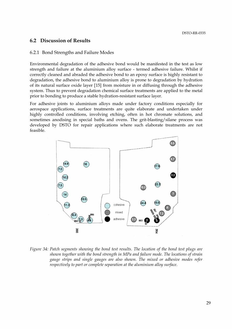
Figure 34: Patch segments showing the bond test results. The location of the bond test plugs are shown together with the bond strength in MPa and failure mode. The locations of strain gauge strips and single gauges are also shown. The mixed or adhesive modes refer respectively to part or complete separation at the aluminium alloy surface.
DSTO-RR-0335
30
Failure within the adhesive, termed cohesive failure is the optimum failure mode since this indicates that the maximum achievable strength in the adhesive has been achieved. However, in the case of fibre composite patches another possible failure mode is within the patch, either separation of surface plies or in the surface matrix resin. Whilst this mode may not represent the optimum strength of the adhesive bond it is acceptable as it occurs at a relatively high stress level.
Cyclic loading, even in the absence of environmental degradation, can cause fatigue damage to the adhesive or bond interfaces resulting in disbonding. The locus of damage is expected to be within the adhesive or at or close to the metal or composite surface (even in the absence of environmental degradation at the metallic surface) or within the composite near-surface plies.
Environmental degradation is unlikely during exposure in the laboratory environment, even in the absence of humidity control, thus environmental degradation, if it occurs, is more likely during service exposure. The location of the patch on the lower wing-skin minimises drying as it would be shaded from direct exposure to sunlight.
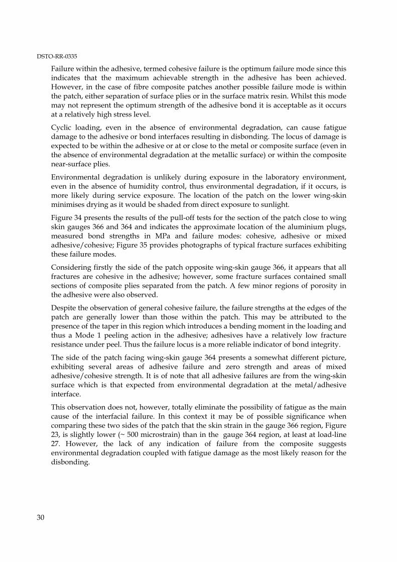
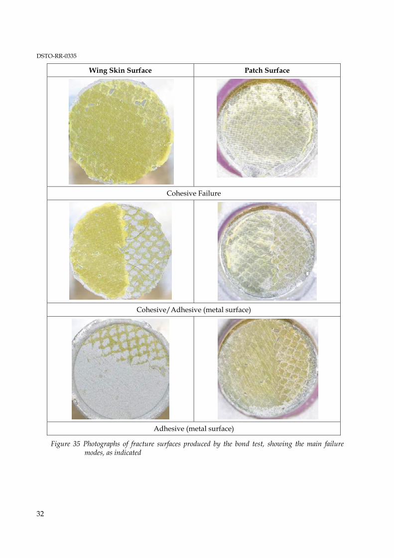
Figure 34 presents the results of the pull-off tests for the section of the patch close to wing skin gauges 366 and 364 and indicates the approximate location of the aluminium plugs, measured bond strengths in MPa and failure modes: cohesive, adhesive or mixed adhesive/cohesive; Figure 35 provides photographs of typical fracture surfaces exhibiting these failure modes.
Considering firstly the side of the patch opposite wing-skin gauge 366, it appears that all fractures are cohesive in the adhesive; however, some fracture surfaces contained small sections of composite plies separated from the patch. A few minor regions of porosity in the adhesive were also observed.
Despite the observation of general cohesive failure, the failure strengths at the edges of the patch are generally lower than those within the patch. This may be attributed to the presence of the taper in this region which introduces a bending moment in the loading and thus a Mode 1 peeling action in the adhesive; adhesives have a relatively low fracture resistance under peel. Thus the failure locus is a more reliable indicator of bond integrity.
The side of the patch facing wing-skin gauge 364 presents a somewhat different picture, exhibiting several areas of adhesive failure and zero strength and areas of mixed adhesive/cohesive strength. It is of note that all adhesive failures are from the wing-skin surface which is that expected from environmental degradation at the metal/adhesive interface.
This observation does not, however, totally eliminate the possibility of fatigue as the main cause of the interfacial failure. In this context it may be of possible significance when comparing these two sides of the patch that the skin strain in the gauge 366 region, Figure 23, is slightly lower (~ 500 microstrain) than in the gauge 364 region, at least at load-line 27. However, the lack of any indication of failure from the composite suggests environmental degradation coupled with fatigue damage as the most likely reason for the disbonding.

DSTO-RR-0335
31
In previous fatigue studies [16] on bonded joints representing repairs, failure mainly occurred in the first ply of the boron/epoxy composite, although it could also occur at the metal interface.
Unfortunately, it is not possible to establish in retrospect if the degradation is due to an inadequacy of the bonding process or inadequate application of the process. However, the observation of local degradation along the wing-skin gauge 364 region but not the 366 region is a strong indication of degradation due to variable processing over the surface of patched region.
Overall the picture of the patch is one of extensive regions of high residual bond strength but with some regions of growing disbonds � but none that would be expected result in loss of the patch, at least for some very considerable time of actual service � assuming no significantly more rapid environmental degradation in service.
However, it is fairly certain that use of the adhesion primer (containing strontium chromate) recommended by DSTO at the time of application of this repair would have greatly reduced the incidence of adhesion failure.
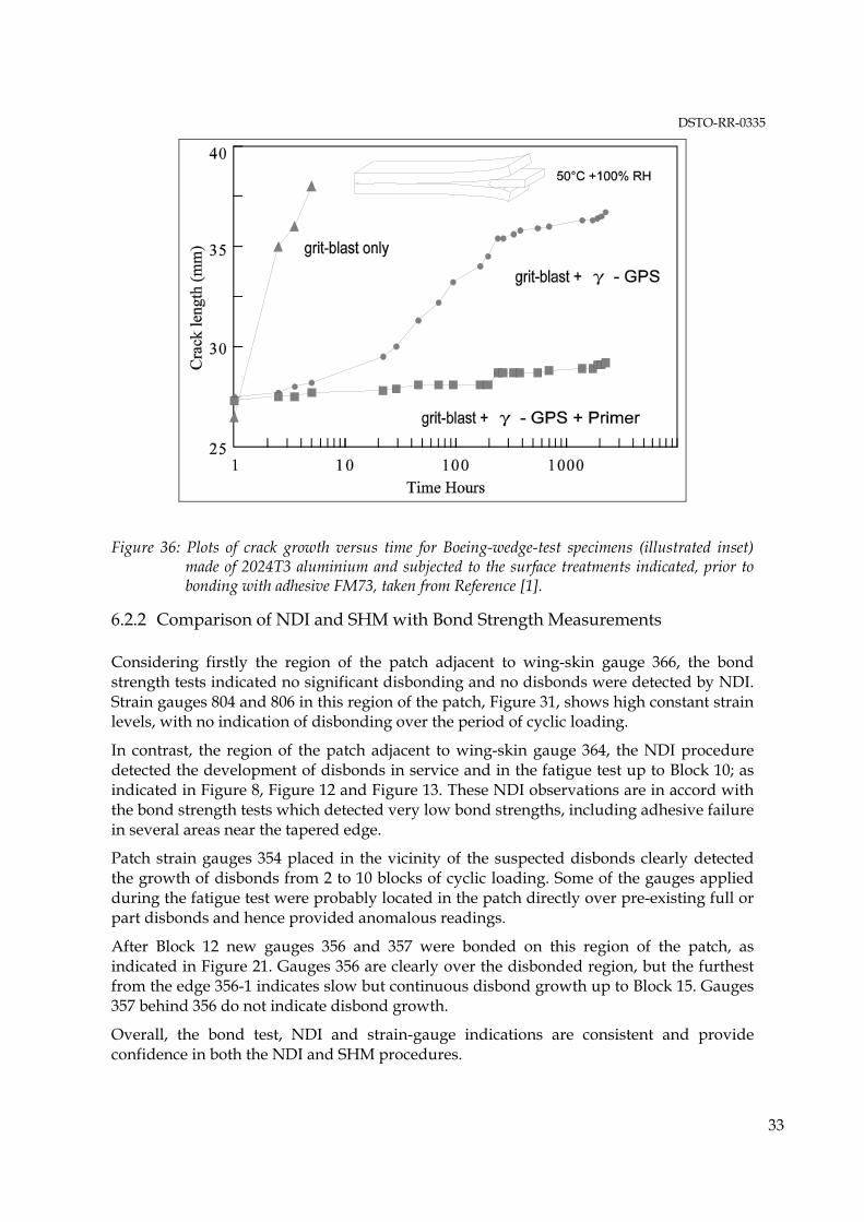
The evidence for this suggestion is shown in Figure 36, which is based on some early work [9] and later confirmed in several other studies, including [15], that the primer increases both the strength and durability of the adhesive bond to the metallic surface.
Figure 36 shows results from the Boeing wedge test in which aluminium alloy strips are bonded together with the adhesive of interest, in this case FM73, following application of the candidate pre-bonding surface treatment. A wedge is then driven between the strips to a prescribed distance and the specimen exposed to 50 ° C in 100% condensing humidity environment. The growth and locus of the disbonding crack are noted. As clearly shown in this figure use of the adhesive primer with the silane process has a very significant effect on reducing growth of the disbonding crack compared to the use of silane process alone.
DSTO-RR-0335
32
Wing Skin Surface Patch Surface
Cohesive Failure
Cohesive/Adhesive (metal surface)
Adhesive (metal surface)
Figure 35 Photographs of fracture surfaces produced by the bond test, showing the main failure modes, as indicated
DSTO-RR-0335
33
Figure 36: Plots of crack growth versus time for Boeing-wedge-test specimens (illustrated inset) made of 2024T3 aluminium and subjected to the surface treatments indicated, prior to bonding with adhesive FM73, taken from Reference [1].
6.2.2 Comparison of NDI and SHM with Bond Strength Measurements
Considering firstly the region of the patch adjacent to wing-skin gauge 366, the bond strength tests indicated no significant disbonding and no disbonds were detected by NDI. Strain gauges 804 and 806 in this region of the patch, Figure 31, shows high constant strain levels, with no indication of disbonding over the period of cyclic loading.
In contrast, the region of the patch adjacent to wing-skin gauge 364, the NDI procedure detected the development of disbonds in service and in the fatigue test up to Block 10; as indicated in Figure 8, Figure 12 and Figure 13. These NDI observations are in accord with the bond strength tests which detected very low bond strengths, including adhesive failure in several areas near the tapered edge.
Patch strain gauges 354 placed in the vicinity of the suspected disbonds clearly detected the growth of disbonds from 2 to 10 blocks of cyclic loading. Some of the gauges applied during the fatigue test were probably located in the patch directly over pre-existing full or part disbonds and hence provided anomalous readings.
After Block 12 new gauges 356 and 357 were bonded on this region of the patch, as indicated in Figure 21. Gauges 356 are clearly over the disbonded region, but the furthest from the edge 356-1 indicates slow but continuous disbond growth up to Block 15. Gauges 357 behind 356 do not indicate disbond growth.
Overall, the bond test, NDI and strain-gauge indications are consistent and provide confidence in both the NDI and SHM procedures.
DSTO-RR-0335
34
7. Discussion
The main focus of this study was to evaluate the effectiveness of ultrasonic NDI and a strain-based SHM approach to detect the growth of disbonds in a composite repair patch bonded to F-111 wing A15-5, during in-flight service in the case of NDI and during the fatigue test in the case of both NDI and SHM. This application provided an almost unique opportunity to gain confidence in bonded repairs to metallic aircraft structure and related non-destructive monitoring technologies.
Despite the incidences of disbonding the patch was fully effective in preventing crack growth for ~ 670 flying hours and for ~ 9000 SFH in the fatigue test. The majority of the patch remained well bonded, although the evidence of some growing disbonds is clearly of concern. The disbonding was probably caused by environmental degradation at the metal surface, and grown by the cyclic loading in service and during the fatigue test. The fact that growth was highly localised indicates that the loss in bond-strength was due to variable processing rather than an intrinsic deficiency in the bonding surface treatment process.
Use of the pre-bonding primer recommended by DSTO would almost certainly have minimised the occurrence of the disbonds. Nevertheless, valid reservations were expressed by RAAF which resulted in the primer not being used in this application. These included concern about control of the thickness of the primer (an important requirement) as well as health and safety.
Based on the use of the bond-strength test as a destructive check, it is concluded that both NDI and SHM are effective in detecting disbonds. Although some anomalous strain readings were obtained in SHM these could reasonably be attributed to the presence of pre-existing disbonds.
The SHM approach thus has excellent potential to ease the certification requirements for bonded composite repairs and extend their scope. However, to fulfil this role the SHM system must be highly reliable, rugged and unobtrusive and as far as feasible standalone.
In general, SHM will be cost-effective (and indeed only required) for demanding applications where NDI can not be easily applied, for example for patch repairs to deeply hidden or inaccessible structure or for particularly critical repairs or where the required frequency of inspection would not be feasible. However, the reliability and probability of detection of the SHM system would have to be demonstrated to ensure it meets the appropriate airworthiness standards.
Importantly SHM must be considered only as a confidence increasing back-up to a well planned repair development program, not as an alternative.
The following extra considerations and improvements to the current system should provide a practically useful strain-based SHM system for monitoring repair patches:
1. Use a sufficiently large number of sensors to allow for failures and anomalous readings.
DSTO-RR-0335
35
2. Locate strain sensors in regions which will provide an early and unambiguous indication of significant damage to the patch system (e.g. the safe-life zone) and on appropriate regions of the parent structure (e.g. in a similar stress field).
3. Chose sensors able to operate reliably in temperature ranges from -50°C to over + 100°C and cyclic strains of 3000 to 4000 microstrain more than 105 cycles.
4. Embed sensors wiring and connections inside the patch or under a protective layer for shielding against mechanical and environmental damage, including abrasion and corrosion and, in the case of wiring and connections, to minimise movement which could lead to fatigue damage.
5. Minimise the size and power requirements of instrumentation and ensure that it is secure against vibration.
Further considerable improvements would result if:
6. Wiring and associated connections were minimised, for example by using wireless transmission techniques.
7. All instrumentation was microminiaturised so they could be embedded in the patch system and able to communicate wirelessly with external data acquisition systems.
8. The system was self powering, using batteries only for backup.
Although conventional resistance strain gauges are reliable, relatively low-cost and quite fatigue and environmentally resistant, alternative strain sensors such as optical fibres (Bragg Grating) and piezoelectric polymer strain sensors may have considerable benefits provided they can meet the operating requirements. For example, piezoelectric polymer strain gauges require no power and have high fatigue life; a single optical fibre can provide hundreds of strain sensors. Optical fibres can also monitor temperature and other parameters, for example they could be used to monitor patch cure; however, the relatively large size of the accompanying instrumentation is currently a significant drawback.
Through a power-harvesting approach electrical power for the SHM system can be obtained from straining of the structure itself, using piezoelectric transducers, as has already proved successful in flight demonstration studies [17] on a �repaired� F/A-18 aileron hinge. This demonstration also included collocated data processing and wireless data downloading.
For the detection of the patched crack, although there was some uncertainty regarding the NDI measurement of the crack under the patch just prior to failure of the wing, there is no reason to doubt that the eddy-current NDI procedure is fully effective. Several other studies have shown that eddy-current procedures can easily detect cracks even under quite thick patches. Boron/epoxy being non-conducting is highly compatible with eddy-current NDI techniques. However, SHM of the crack would alleviate concern that significant crack growth may be missed between non-destructive inspections and indeed may require relatively little extra effort for this capability to be included with the patch SHM system.
Strain-based SHM procedures based on sensors attached to the parent structure under the patch should be highly effective in detecting crack growth but may act as local disbonds.
DSTO-RR-0335
36
Strain sensors bonded to the patch over the cracked region could detect strain changes related to growing cracks, but are a less direct alternative.
Active approaches are an attractive alternative to the passive strain-based SHM procedure adopted in the current application. For example an approach based on embedded or surface-mounted piezoelectric actuators and sensors, is also very promising [18]. Here the SHM approach is very similar to conventional ultrasonic NDI where patch disbonds are detected for example by attenuation or reflected ultrasonic acoustic waves.
8. Conclusions
• A boron/epoxy composite patch designed and applied by RAAF and successfully repaired a large fatigue crack in the primary wing skin structure A15-5 of an ADF F-111. The patch, despite some disbonding, inhibited crack growth for ~ 670 actual flying hours and ~ 9000 simulated flying hours. Growth of the crack was experienced only after a significant stress increase in the wing skin caused by failure of an auxiliary spar and just prior to catastrophic wing failure from a crack initiated from a region well away from the repaired crack.
• Although the eddy-current NDI procedure used for crack detection was successful in detecting the crack under the patch for most of the life of the repair, NDI either missed or did not detect the final growth of the crack just prior to failure of the wing. Since confidence in the ability of the NDI to detect the crack is very high it seems more likely that the final growth was simply just missed.
• The ultrasonic NDI and strain-gauge SHM procedures for detecting patch disbonding were checked by direct measurements of the residual bond strength between the patch and the wing skin. Based on this assessment both procedures appear to be highly effective in detecting disbonding.
• A strain-based SHM procedure using conventional resistance strain gauges appears to be a feasible approach for in-service monitoring of critical or difficult to access repairs, providing sufficient redundancy is built into the gauging system. Developments in power harvesting and application of miniaturised data processors, wireless data transmission and possible use of alternative more robust sensors, such as optical fibres, have the potential to make this SHM approach highly reliable and cost-effective.
• Disbonding of the patch in some regions was probably caused by environmental degradation at the surface of the wing skin. Based on previous DSTO work, it is concluded that use of the recommended primer in association with the grit/blast silane surface treatment would have prevented or at least considerably reduced the degradation. Use of the primer is strongly recommended for applications of crack patching where long service life in adverse environments is required.
DSTO-RR-0335
37
References
1 Baker A.A., �Bonded Composite Repair of Metallic Aircraft Components�, Paper 1 in AGARD-CP-550 Composite Repair of Military Aircraft Structures, 1994.
2 Baker A.A., Rose L.F.J, Jones R, Editors, �Advances in the Bonded Composite Repair of Aircraft Structure�, Elsevier 2002.
3 Composite Materials and Adhesive Bonded Repairs, RAAF Standard Engineering C5033` Issue 1, 4 September 1995.
4 Van Blaricum T, Ord D, Koning R, and Hobson M, Damage Enhancement Testing of RAAF F-111C Wing A15-5, , DSTO-TR-1640, 2004
5 IBID Ref 2 Walker K.F. and Rose L.R.F., Chapter 27 �Case History F-111 Lower Wing Skin Repair Substantiation.
6 IBID Reference 2, Baker A.A, Chapter 1 �Introduction and Overview�,
7 IBID Reference 2, Chalkley P and Baker A.A. Chapter 4 �Adhesives Characterisation and Data Base�.
8 IBID Reference Chalkley P.D. Wang C.H. and Baker Chapter 5 �Fatigue Testing of Generic Bonded Joints�.
9 Baker, A. A. and Chester, R. J., Int. J. �Minimum Surface Treatments For Adhesively Bonded Repairs� Adhesion and Adhesives 12 (1992) 73
10 Anderson M and Geddes R private communication, April 2000.
11 IBID Reference 2, Baker A.A. �Certification Issues for Critical Repairs.�
12 Baker A.A. and Jones R. Bonded Repair of Aircraft Structures, Chapter 6 �Crack Patching Experimental Studies Practical Applications� Martinus Nijhoff, 1988
13 Baker A. A., Chester R.J., Davis M.J., Retchford J.A and Roberts J.D., �The Development of a Boron/Epoxy Doubler System For The F-111 Wing Pivot Fitting - Materials Engineering Aspects� Composites 24 (1993), pp. 511 - 521.
14 ASTM D4541-95, "Standard Test Method for Pull-Off Strength of Coatings Using Portable Adhesion Testers", 1995 Annual Book of ASTM Standards, Section 6, Volume 6.01, ASTM, Pennsylvania, 1995.
15 IBID Reference 2 Anott D., Rider A., and Mazza J. Chapter 3 �Surface Treatment and Repair Bonding�
16 IBID Reference 2, Chalkley P.D., Wang C.H. and Baker A.A., Chapter 5 �Fatigue Testing of Bonded Joints�
17 Galea S.C., van der Velden S., Powlesland I., Nguyen Q., Ferrararotto P and Konak M., �Flight Demonstrator of a Self-Powered SHM System on a Composite Bonded Patch Attached to an F/A-18 Aileron Hinge�, Proceedings of the First Asia-Pacific Workshop on Structural Health Monitoring (APWSHM) Japan 2006.
DSTO-RR-0335
38
18 Rosalie S.C. and Rajic N., �A Feasibility Study into the Active Smart Patch Concept for Composite Bonded Repairs� DSTO-TR-XXX , 2007
DSTO-RR-0335
39
Appendix 1:
A 1 Examination of the Crack Under Patch in Wing A15-5
This crack is located in the lower wing skin at a feature in the design intended to allow the flow of fuel between the bays on each side of the forward auxiliary spar. The feature is an approximately elliptical shaped hole between the spar cap and skin. The hole has removed material from the land on the skin, reducing local thickness to the basic skin thickness, a reduction from some 8mm to 3.5mm, and has also reduced the thickness in the spar cap by a similar amount. The length of the ellipse is some 20 mm and the thinnest section of the skin about 5mm. The effect of this material removal is dramatic, high tensile stresses in the skin will result in the skin membrane, over the location of the hole, attempting to move its neutral axis into line with the general location of the neutral axis in the skin. This means that the skin will bend locally upwards, placing the curved inside surface of the skin in a large amount of tension.
The local bending fields during the CPLT and other high positive g events are probably sufficient to generate plastic yielding in tension in the material in the inner surface of the skin over the thinnest part. When the loads are released, spring back will put this region into compression. During service, loads sufficient to cause tension in this area will generate cracking by fatigue. The compression forces will still be acting whenever the wing is at rest, ensuring the crack faces are tightly pressed together. In addition, any fuel in the wing will fill the crack, and if present, reverted sealant will also fill the crack. So the combination of minimum crack face separation and a crack filled with fluid would both tend to allow ultrasonic energy to pass through the crack without a substantial loss or reflection; making detection more difficult, and maybe even impossible.
The crack in A15-5 was repaired after 4749.5 hours in service by applying a boron patch to the external surface of the wing. The aircraft was then flown until it reached 5418 hours, removed from the aircraft and sent to DSTO Melbourne for testing. Failure occurred after 13507 hours (5418 hours in service and 8089 hours of test loads).
Cracks commenced to grow in skin hole AAS047, spar hole AAS047, spar hole AAS048 and many other locations, depending upon the hole finish, the degree of interference and the level of alternating stress when the wing was placed in the rig. It must also be stated that many other cracks, formed during service were present in the wing.
As the crack in the skin hole AAS047 developed, so did the cracks at other locations.
At some stage the crack opening caused by the skin crack provided bending and shear forces on the fastener in hole CS045, this fastener then failed, or it may already have been failed by other mechanisms (the detailed investigation of this failure is still to be done). The failure of this fastener would then allow more motion between the two halves of the skin, and the next time a large load was applied to the wing (CPLT or the load at 182 hours into the 500 SFH hour block) the Aft Auxiliary Spar failed through hole AAS048. The skin crack would then have more freedom to open further, allowing the crack to extend across the lower surface of the wing, and producing the witness marks on the skin where the broken end of the aft auxiliary spar rubbed on the skin. Note that the geometry of the
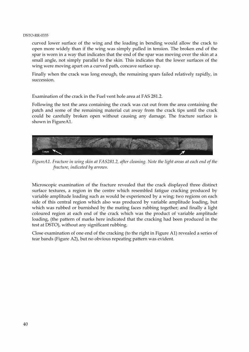
DSTO-RR-0335
40
curved lower surface of the wing and the loading in bending would allow the crack to open more widely than if the wing was simply pulled in tension. The broken end of the spar is worn in a way that indicates that the end of the spar was moving over the skin at a small angle, not simply parallel to the skin. This indicates that the lower surfaces of the wing were moving apart on a curved path, concave surface up.
Finally when the crack was long enough, the remaining spars failed relatively rapidly, in succession.
Examination of the crack in the Fuel vent hole area at FAS 281.2.
Following the test the area containing the crack was cut out from the area containing the patch and some of the remaining material cut away from the crack tips until the crack could be carefully broken open without causing any damage. The fracture surface is shown in FigureA1.
FigureA1. Fracture in wing skin at FAS281.2, after cleaning. Note the light areas at each end of the fracture, indicated by arrows.
Microscopic examination of the fracture revealed that the crack displayed three distinct surface textures, a region in the centre which resembled fatigue cracking produced by variable amplitude loading such as would be experienced by a wing; two regions on each side of this central region which also was produced by variable amplitude loading, but which was rubbed or burnished by the mating faces rubbing together; and finally a light coloured region at each end of the crack which was the product of variable amplitude loading, (the pattern of marks here indicated that the cracking had been produced in the test at DSTO), without any significant rubbing.
Close examination of one end of the cracking (to the right in Figure A1) revealed a series of tear bands (Figure A2), but no obvious repeating pattern was evident.
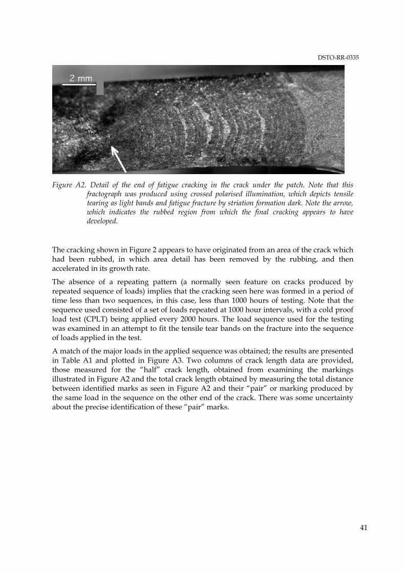
DSTO-RR-0335
41
Figure A2. Detail of the end of fatigue cracking in the crack under the patch. Note that this fractograph was produced using crossed polarised illumination, which depicts tensile tearing as light bands and fatigue fracture by striation formation dark. Note the arrow, which indicates the rubbed region from which the final cracking appears to have developed.
The cracking shown in Figure 2 appears to have originated from an area of the crack which had been rubbed, in which area detail has been removed by the rubbing, and then accelerated in its growth rate.
The absence of a repeating pattern (a normally seen feature on cracks produced by repeated sequence of loads) implies that the cracking seen here was formed in a period of time less than two sequences, in this case, less than 1000 hours of testing. Note that the sequence used consisted of a set of loads repeated at 1000 hour intervals, with a cold proof load test (CPLT) being applied every 2000 hours. The load sequence used for the testing was examined in an attempt to fit the tensile tear bands on the fracture into the sequence of loads applied in the test.
A match of the major loads in the applied sequence was obtained; the results are presented in Table A1 and plotted in Figure A3. Two columns of crack length data are provided, those measured for the �half� crack length, obtained from examining the markings illustrated in Figure A2 and the total crack length obtained by measuring the total distance between identified marks as seen in Figure A2 and their �pair� or marking produced by the same load in the sequence on the other end of the crack. There was some uncertainty about the precise identification of these �pair� marks.
DSTO-RR-0335
42
Table A1. Crack Depth versus hours
Hours �Half� Crack Length mm Crack Length mm Comments
0 0.01 0.02 Notional initial defect size
4749.5 16 36 Patch Applied
4749.5 19.9 45.1 Patch Applied
12400 21.0 46.3
12685 23.03 48.4
12835 23.95 51.5
12930 24.69 52.2
12990 25.22 53.2
13158 26.34 54.7
13490 28.41 58 Near end of test
Conclusions.
The cracking in the skin at FAS 281 was formed in service and following the application of the patch, growth stopped. Then during the test of the wing A15-5 the Aft Auxiliary Spar failed, possibly at the 12000-hour CPLT and the redistribution of loads caused by this structural failure resulted in increased stress on the other spars, and the crack under the patch then continued to propagate. The crack growth in the skin produced by the service loads could be delineated in more detail using the service load history of the wing, such an undertaking requires a significant effort.
Noel Goldsmith
10/6/2003
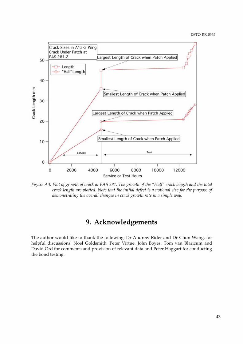
DSTO-RR-0335
43
Figure A3. Plot of growth of crack at FAS 281. The growth of the “Half” crack length and the total crack length are plotted. Note that the initial defect is a notional size for the purpose of demonstrating the overall changes in crack growth rate in a simple way.
9. Acknowledgements
The author would like to thank the following: Dr Andrew Rider and Dr Chun Wang, for helpful discussions, Noel Goldsmith, Peter Virtue, John Boyes, Tom van Blaricum and David Ord for comments and provision of relevant data and Peter Haggart for conducting the bond testing.
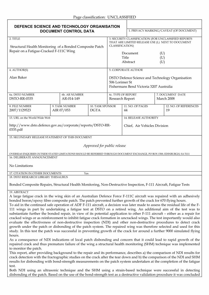
Page classification: UNCLASSIFIED
DEFENCE SCIENCE AND TECHNOLOGY ORGANISATION
DOCUMENT CONTROL DATA 1. PRIVACY MARKING/CAVEAT (OF DOCUMENT)
2. TITLE Structural Health Monitoring of a Bonded Composite Patch Repair on a Fatigue-Cracked F-111C Wing
3. SECURITY CLASSIFICATION (FOR UNCLASSIFIED REPORTS THAT ARE LIMITED RELEASE USE (L) NEXT TO DOCUMENT CLASSIFICATION) Document (U) Title (U) Abstract (U)
4. AUTHOR(S) Alan Baker
5. CORPORATE AUTHOR DSTO Defence Science and Technology Organisation 506 Lorimer St Fishermans Bend Victoria 3207 Australia
6a. DSTO NUMBER DSTO-RR-0335
6b. AR NUMBER AR-014-149
6c. TYPE OF REPORT Research Report
7. DOCUMENT DATE March 2008
8. FILE NUMBER 2007/1129523
9. TASK NUMBER AIR 07/053
10. TASK SPONSOR DGTA
11. NO. OF PAGES 44
12. NO. OF REFERENCES 19
13. URL on the World Wide Web http://www.dsto.defence.gov.au/corporate/reports/DSTO-RR-0335.pdf
14. RELEASE AUTHORITY Chief, Air Vehicles Division
15. SECONDARY RELEASE STATEMENT OF THIS DOCUMENT
Approved for public release OVERSEAS ENQUIRIES OUTSIDE STATED LIMITATIONS SHOULD BE REFERRED THROUGH DOCUMENT EXCHANGE, PO BOX 1500, EDINBURGH, SA 5111 16. DELIBERATE ANNOUNCEMENT No Limitations 17. CITATION IN OTHER DOCUMENTS Yes 18. DSTO RESEARCH LIBRARY THESAURUS Bonded Composite Repairs, Structural Health Monitoring, Non-Destructive Inspection, F-111 Aircraft, Fatigue Tests 19. ABSTRACT A large fatigue crack in the wing skin of an Australian Defence Force F-111C aircraft was repaired with an adhesively bonded boron/epoxy fibre composite patch. The patch prevented further growth of the crack for 670 flying hours. To aid in the continued safe operation of ADF F-111 aircraft, a decision was later made to assess the residual life of the F-111 wings in part by undertaking a fatigue test at DSTO on a retired wing. An additional aim of the test was to substantiate further the bonded repair, in view of its potential application to other F-111 aircraft � either as a repair for cracked wings or as reinforcement to inhibit fatigue crack formation in uncracked wings. The test importantly would also evaluate the effectiveness of non-destructive inspection (NDI) and other non-destructive procedures to detect crack growth under the patch or disbonding of the patch system. The repaired wing was therefore selected and used for this study. In this test the patch was successful in preventing growth of the crack for around a further 9000 simulated flying hours. As a consequence of NDI indications of local patch disbonding and concern that it could lead to rapid growth of the repaired crack and thus premature failure of the wing a structural health monitoring (SHM) technique was implemented to monitor the patch. This report, after providing background to the repair and its performance, describes a) the comparison of NDI results for crack detection with the fractographic studies on the crack after the tear down and b) the comparison of the NDI and SHM results for disbonding with bond-strength measurements on the patch system undertaken at the completion of the fatigue test. Both NDI using an ultrasonic technique and the SHM using a strain-based technique were successful in detecting disbonding of the patch. Based on the use of the bond-strength test as a destructive validation procedure it was concluded

that both the NDI and the SHM techniques were highly effective in detecting disbonds and that the strain-based SHM technique (with several significant improvements) could be used for in-flight monitoring of repair patches in demanding or critical applications.
Page classification: UNCLASSIFIED