Embed Size (px)
Citation preview

Fast Morphological Image Processing on GPU using CUDA
Dissertation
Submitted in partial fulfillment of the requirements
for the degree of
Master of Technology in Computer Engineering
By
Mugdha A. Rane
MIS No: 121122016
Under the guidance of
Dr. Vandana Inamdar Department of Computer Engineering and Information Technology
College of Engineering, Pune
Pune - 411005
June, 2013

DEPARTMENT OF COMPUTER ENGINEERING AND
INFORMATION TECHNOLOGY,
COLLEGE OF ENGINEERING, PUNE
CERTIFICATE
This is to certify that the dissertation titled
Fast Morphological Image Processing on GPU using CUDA
has been successfully completed
By
Mugdha A. Rane
121122016
And is approved for the partial fulfillment of the requirements for the degree of
Master of Technology, Computer Engineering
Dr. Vandana Inamdar
Project Guide,
Department of Computer Engineering
and Information Technology,
College of Engineering, Pune,
Shivaji Nagar, Pune-411005.
Dr. J. V. Aghav
Head,
Department of Computer Engineering
and Information Technology,
College of Engineering, Pune,
Shivaji Nagar, Pune-411005.
Date _____________

Abstract
A mathematical morphology is used as a tool for extracting image components that
are useful in the representation and description of region shape. The mathematical
morphology operations of dilation, erosion, opening, and closing are important building
blocks of many other image processing algorithms. The data parallel programming provides
an opportunity for performance acceleration using highly parallel processors such as GPU.
NVIDIA CUDA architecture offers relatively inexpensive and powerful framework for
performing these operations. However the generic morphological erosion and dilation
operation in CUDA NPP library is relatively naive, but it provides impressive speed ups only
for a limited range of structuring element sizes. The vHGW algorithm is one of the fastest for
computing morphological operations on a serial CPU.
This algorithm is compute intensive and can be accelerated with the help of GPU.
This project implements vHGW algorithm for erosion and dilation independent of structuring
element size has been implemented for different types of structuring elements of an arbitrary
length and along arbitrary angle on CUDA 5.0 programming environment with GPU
hardware as GeForce GTX 480. The results show maximum performance gain of 20 times
than the conventional serial implementation of algorithm in terms of execution time.
Index Terms - morphological image processing, erosion, dilation, vHGW, GPU and CUDA

ACKNOWLEDGEMENTS
I express my sincere gratitude towards my guide Prof. Vandana Inamdar for her constant
help, encouragement and inspiration throughout the project work. I am extremely thankful to
Dr. J. V. Aghav and Dr. V. K. Pachghare for giving me constant support, without which this
work would not have been possible. Last but not least, I would like to thank my family and
friends, who have been a source of encouragement and inspiration throughout the duration of
the project.
Mugdha A. Rane
College of Engineering, Pune

INDEX
1. Introduction…………………………………………………………....................................1
1.1 Morphological Image Processing………………………………………………….1
1.2 Dilation and erosion….……………………………………………………. ……..2
1.3 vHGW Algorithm……………………………………………………………….....7
1.4 Applications of grayscale morphology………………………………………….....8
1.5 GPU…………………………………………………………………………. …..10
1.6 CUDA……………………………………………………………………….. …..13
1.7 Motivation………………………………………………………………………..14
1.8 Objective………………………………………………………………………....14
2. Literature Survey…………………………………………………………………………..15
2.1 Existing Approach and their performance..………………………………………15
2.2 Research Gap………………..……………………………………………………17
3. Line erosions and dilations at arbitrary angles…………………………………………….18
3.1 Definition of an array of indices………………………………………………….18
3.2 Processing lines at arbitrary angles………………………………………………18
3.3 Processing lines of arbitrary length………………………………………………18
3.4 Algorithm………………………………………………………………………...19
3.5 Example…………………………………………………………………………..19
4. vHGW algorithm and Implementation…………………………………………………….21
5. Experiments and Results…………………………………………………………………..24
6. Conclusion and Future work………………………………………………………………29
6.1 Conclusion………………………………………………………………………..29
6.2 Future work………………………………………………………………………29
Bibliography………………………………………………………………………………….30
LIST OF FIGURES
Fig. 1.1: Examples of different structuring elements……….…….………………………...…1
Fig.1. 2: Structuring elements in rectangular form……………………………………………2
Fig. 1.3: Brocken character image...………………...…………………………………………3
Fig. 1.4: Example of erosion ….………………………………………………………………4
Fig.1. 5: Binary image corrupted with noise…………………………………………………..6
Fig.1.6: SIMD Architecture …...………………………………………………………………9
Fig.1.7: Threads batching in CUDA........................................................................................10
Fig. 3.1: An example of an opening by a line at an arbitrary angle………………………….19
Fig. 3.2: An example of a series of linear openings………………………………………….19
Fig. 5.1: Speedup Gain of GPU vs. CPU…………………...……….……………………….26
Fig. 5.2: Original Image „rectus‟ of size 1024×1024………………………………………...27
Fig. 5.3: Dilation with structuring element size 31 and angle90…………………………….27
Fig. 5.4: Dilation with structuring element size 31 and angle 0……………………………...28
Fig. 5.5: Erosion with structuring element size 31 and angle 90…………………………….28
Fig. 5.6: Erosion with structuring element size 31 and angle 0……………………………...29

LIST OF TABLES
Table 5.1: Performance of an algorithm on CPU and GPU…………………………………24

CHAPTER 1
INTRODUCTION
1.1 Morphological Image Processing:
1.1.1 Morphology and Sets:
Morphology is formulated in terms of set theory. Sets represent objects in image.
Morphological processing is constructed with operations on sets of pixels. Basically it is
constructed for binary images. The set of all white pixels in a binary image is a complete
morphological description of an image [5]. In binary images, the sets are members of the 2D
integer space Z2, where each element of a set is a tuple (2D vector) whose coordinates are the
(x, y) coordinates of a white (or black) pixel in the image. The same can be extended for grey-
scale images. Gray-scale images can be represented as sets, whose components are in Z3: two
components are coordinates of a pixel and the third its discrete intensity value.
Morphological operations for binary images provide a basic techniques and those
operations for gray scale images requires more sophisticated mathematical concepts for
extracting image components that are useful in the representation and description of region
shape, such as boundaries, skeletons, etc. [14].
1.1.2 Structuring Element:
The structuring elements are small set of sub images used to probe an analyzed image
for properties of interest. The structuring element has both a shape and an origin.
Fig. 1.1 : Examples of different structuring elements

In Fig. 1.1 the origins of SEs are marked by a black dot and shaded square denotes a
member of the SE. When working with images, SEs should be rectangular. Therefore,
smallest numbers of background elements are appended to form rectangular shape as shown
in Fig 1.2 [1].
Fig.1.2 : Structuring elements in rectangular form
Depending on shape, structuring element can take additional parameters. There are
two types of structuring element, i) Flat Structuring Element, ii) Non-flat Structuring
Element.
Basically, Flat structuring element are used for two dimensional image and Non flat
structuring element for three-dimensional object, the parameter added for Non-flat i.e. height.
The structuring element like: Disk, Diamond, Arbitrary shape, Pair, Periodic line, Rectangle,
Line, Disk and Octagon are belongs to flat structuring element, whereas Arbitrary and Ball
are the non-flat Structuring element.
1.2. Dilation and Erosion
Dilation and erosion are basic morphological processing operations. They are defined
in terms of more elementary set operations, but are employed as the basic elements of many
algorithms. Both dilation and erosion are produced by the interaction of a structuring
element.
1.2.1 Dilation:
Dilation “grows” or “enlarges” objects in a binary image. The manner and extend of
this growth image is controlled by the structuring element.
}ˆ{ ΦA)Bz|(BA z
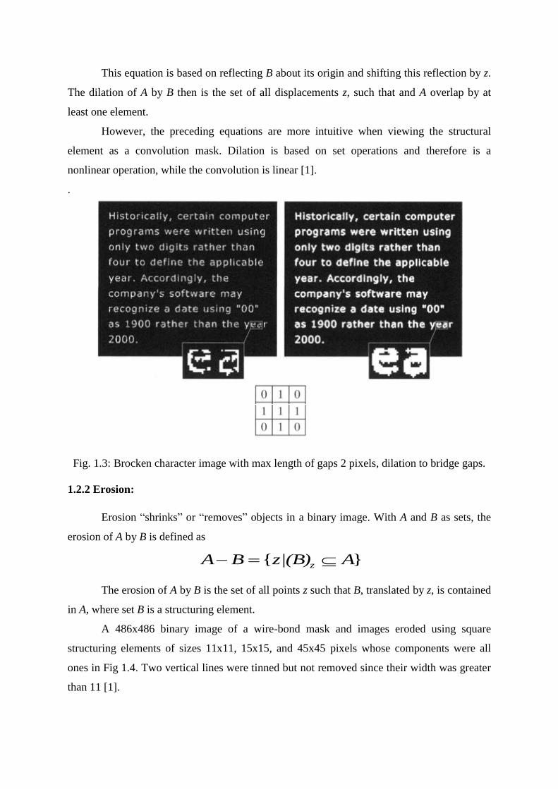
This equation is based on reflecting B about its origin and shifting this reflection by z.
The dilation of A by B then is the set of all displacements z, such that and A overlap by at
least one element.
However, the preceding equations are more intuitive when viewing the structural
element as a convolution mask. Dilation is based on set operations and therefore is a
nonlinear operation, while the convolution is linear [1].
.
Fig. 1.3: Brocken character image with max length of gaps 2 pixels, dilation to bridge gaps.
1.2.2 Erosion:
Erosion “shrinks” or “removes” objects in a binary image. With A and B as sets, the
erosion of A by B is defined as
The erosion of A by B is the set of all points z such that B, translated by z, is contained
in A, where set B is a structuring element.
A 486x486 binary image of a wire-bond mask and images eroded using square
structuring elements of sizes 11x11, 15x15, and 45x45 pixels whose components were all
ones in Fig 1.4. Two vertical lines were tinned but not removed since their width was greater
than 11 [1].
}{ Az|(B)BA z

Fig. 1.4: Example of erosion
In image processing applications, dilation and erosion are used most often in various
combinations. An image undergoes a series of dilations and/or erosions using the same or
different structuring elements.
1.2.3 Opening and Closing:
Opening generally smoothes the contour of an object and eliminate thin protrusions.
The opening of a set A by structuring element B is defined as
Therefore, the opening A by B is the erosion of A by B, followed by a dilation of the
result by B.
Closing also tends to smooth sections of contours but fusing narrow breaks and long,
thin gulfs and eliminating small holes and filling gaps in the contour. The closing of a set A
by structuring element B is defined as
BBABA )(

Therefore, the closing A by B is the dilation of A by B, followed by an erosion of the
result by B.
1.2.4 Duality:
Erosion and dilation are duals of each other with respect to set complementation and
reflection.
Erosion of A by B is the complement of the dilation of the complement of A by the
reflection of B and vice versa. Duality is particularly ˆ useful when the SE is symmetric with
respect to its origin, so that. Then we can obtain the erosion of an image by B simply by
dilating its background (complement of A) with the same structuring element and
complementing the result.
1.2.5 Hit or Miss Transformation:
The hit or miss transformation is useful to match specified configurations of pixels in
an image, such as isolated foreground pixels, or pixels that are endpoints of line segments.
1.2.6 Application with example of forensics:
Employment of fingerprints as evidence of crime has been one of the most important
utilities in forensics since 19th century. Where there are no witness to a certain crime, finger
prints can be very useful in determining the offenders. In most cases, they are incomplete
and degraded. The individual features that uniquely identify a fingerprint are called minutiae.
Thus, the basic ridge pattern together with the minutiae and their location on the finger print
pattern uniquely identify a fingerprint. The Morphological Image Processing enhances the
degraded noisy and / or incomplete latent fingerprints [4].
BBABA )(
)ˆ()( BABA cc

Fig.1. 5: Binary image corrupted with noise ->Eroded Image ->Opening of A (dilation of
eroded image)->Dilation of Opening->Closing of Opening
In physics and related fields, computer techniques routinely enhance images of
experiments in areas such as high-energy plasmas and electron microscopy. Similarly
successful applications of image processing concepts can be found in astronomy, biology,
nuclear medicine, law enforcement, and defense.
1.3. vHGW Algorithm:
This is the first grayscale morphology algorithm to compute dilation and erosion with
complexity independent of the size of the SE. It is simple and elegant. It works for all
structuring elements composed of horizontal and/or vertical linear elements, and requires not
more than 3 pixel value comparisons for each output pixel. The algorithm has been recently
refined bringing the number down below 1.5 comparisons per output pixel, at a cost of
significantly increased complexity.
1.3.1 Steps:
I. Image rows are partitioned into segments of length p with (p-1)/2 columns of overlap
on each side to form a window of size 2p-1, centered at p-1, 2p-1, 3p-1, ……
II. For each pixel k=0 to (p-1) in a given window w, a suffix max array R is created for
the pixels left of center
a. R[k] = max(w[j]) : j=k …(p-1)
and a prefix max array S is created for the pixels right of center (p-1)…(2p-2),
b. S[k]=max(w[p-1+j]): j=0 …. K
c. (R[k] and S[k] are merged together to compute max filter)
III. For each pixel (p-1)/2 <= j < p+ (p-1)/2 in w(the segment of length p), the dilation
result is
a. result[j]=max(R[j-m],S[j+m]), where m=(p-1)/2
1.3.2 Performance Analysis:
There are two stages to the vHGW algorithm
I. In preprocessing step, computing R[k] and S[k] and to find their max requires 2(p-1)
comparisons
II. In merging step, merging of R[k] and S[k] requires p-2 comparisons
a. Since this procedure computes the maximum of p windows in total, we have
that number of comparisons per window is (2(p-1)+(p-2))/p=3-4/p
b. For large p, we have that the preprocessing step requires two comparison
operations per element, while the merge step requires one more such
comparison.

1.4 Applications of Gray scale morphology:
Gray morphological operations are used generally to extract the edge of the image for
the conditions, the multi-level geodetic expansion to expand to fill the target area, through
which the algorithm can improve the detection of image accuracy, enhanced noise immunity,
effectively identify the target and also to efficiently reduce the number of skeleton points and
the entropy of morphological decomposition.
Blood vessel edge enhancement and reconnection: candidate vessels as well as
their orientation fed to a spatially-variant morphological filter for reconnection and
reconstruction of blood vessels.
Geographic pattern recognition for a satellite remote sensing image: to detect the
edge information of the spectrum data. These operations are useful for detection of
rapid changes of a gray tone function such as class boundaries. Detected images and
spectral images are given to the input layer of a three-layer back propagation neural
network and are learned.
Recognition and classification of vehicle on the traffic road in the hi-resolution
satellite image: The satellite image contains the vehicle characters pixel set and alike
vehicle characters pixel set. So, there are a series of pattern recognition methods from
morphological image preprocessing to the LVQ artificial neural network works.
Solution to problem of luminal contour detection in intravascular ultrasound
images: Median and standard deviation are used as features for segmentation process.
High correlation coefficients were found between lumen regions manually and
automatically defined when area, mean gray level, and standard deviation of the
lumen regions were compared using morphology.
A robust vision system for vehicle license plate recognition : to detect the region of
a vehicle license plate from an image based on grey scale morphological operations
even when the images are fairly complex, in poor illumination, and noisy
Industrial parts recognition and inspection by image morphology: For industrial
parts and tool recognition and inspection image morphology techniques are used
along with a recursive adaptive thresholding algorithm transforms a gray-level image
into a set of multiple-level regions of objects. This algorithm uses morphological
erosion with a large symmetrical concave structuring element. A distance
transformation algorithm transforms these binary image regions into the minimum

distance from each object point to the boundary of the object. This algorithm also uses
morphological erosion
Multiresolutional texture analysis based on morphological techniques : The
power of morphology is used as a tool for analysis of grey-level images, and
especially texture. Textures are investigated by extracting a local fractal signature for
a range of scales. The variation with changing resolution then characterizes the
texture.
Image matching using morphological operations: A morphological distance is used
to measure the similarity between images. The shape representation for this new
method utilizes morphological image opening and closing of the input image at
different scales of a primary and rotated structuring elements. The areas of the opened
and closed images are computed for each structure element at each scale to construct
the feature vector of each input image. It is compatible with human visual system
which is insensitive to some changes on images such as rotation, noise, scale, and
filtering also it proves to be more useful than convolution operations in
industrial applications for detect identification.
Extraction of grid patterns on stamped metal sheets: To validate models of sheet
metal forming processes, experiments with sheets of metal marked with grids are
performed. A method for measuring the deformed grid after processing is based on
morphological image processing. The resulting process offers a low computational
complexity, combined with easiness for describing the element form. The algorithm is
exemplified with granulometry. Quantum dots are segmented using a multi-scale
morphologic decomposition.
Application of Morphological Operations in Human Brain CT Image with SVM:
The computer aided diagnosis is applied to the brain CT image processing. We
compared performance of morphological operations in extracting three types of
features i.e. gray scale, symmetry and texture. SVM, MLPNN and RBFNN are used
to build classifiers for normal and abnormal brain CT image. It shows that
morphological operation can improve the accuracy.
Morphological detection based on size and contrast criteria application to cells
detection: A detection algorithm relying on size and contrast criteria is suitable for a
large range of applications where a priori information about the size and the contrast
of the objects to detect is available. The detection is performed in three separate steps.

All these steps make use of morphological. As an example, this algorithm is applied
to the automatic detection of spermatozoa.
1.5. GPU:
A Graphics Processing Unit or GPU (or also called as VPU) is a specialized circuit
designed to rapidly manipulate and alter memory in such a way so as to accelerate the
building of images in a frame buffer intended for output to a display [8].
1.5.1 Flynn’s Classification:
Michael Flynn introduced a classification of various computer architectures based on
notions of instruction (I) and data streams (D).
1. Conventional sequential machines are called SISD Computers.
2. Vectors are equipped with scalar and vector hardware or appear as SIMD
machines.
3. Parallel computers are reserved for MIMD machines.
4. An MISD machines are modeled. The same data stream flows through a linear
array of processors executing different instruction streams.
1.5.2 SIMD Architecture:
Fig.1.6: SIMD Architecture
This architecture describes computers with multiple processing elements that perform
the same operation on multiple data simultaneously. It exploits data level parallelism.
Graphics related operations generally perform the „same‟ operation on a large number
of Pixels.
e.g. Changing the brightness
• R,G,B values are read from memory
• A particular value is added or subtracted
• Resulting values are written back to memory
• Same instruction getPixel() can be applied on a bulk of pixels.
Same instruction add() can be applied on that bulk to change the brightness.
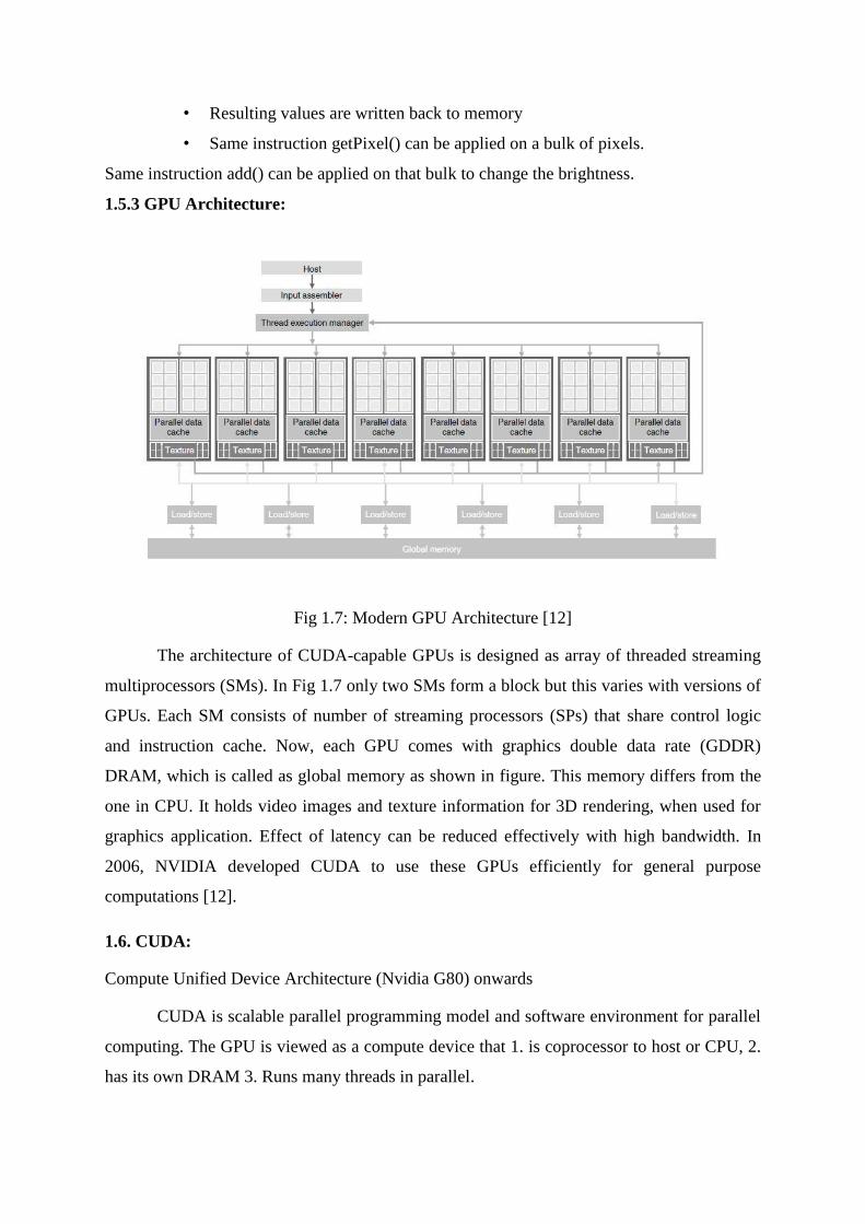
1.5.3 GPU Architecture:
Fig 1.7: Modern GPU Architecture [12]
The architecture of CUDA-capable GPUs is designed as array of threaded streaming
multiprocessors (SMs). In Fig 1.7 only two SMs form a block but this varies with versions of
GPUs. Each SM consists of number of streaming processors (SPs) that share control logic
and instruction cache. Now, each GPU comes with graphics double data rate (GDDR)
DRAM, which is called as global memory as shown in figure. This memory differs from the
one in CPU. It holds video images and texture information for 3D rendering, when used for
graphics application. Effect of latency can be reduced effectively with high bandwidth. In
2006, NVIDIA developed CUDA to use these GPUs efficiently for general purpose
computations [12].
1.6. CUDA:
Compute Unified Device Architecture (Nvidia G80) onwards
CUDA is scalable parallel programming model and software environment for parallel
computing. The GPU is viewed as a compute device that 1. is coprocessor to host or CPU, 2.
has its own DRAM 3. Runs many threads in parallel.

1.6.1 CUDA Program Structure:
A CUDA program is a serial program with parallel sections. This CPU and GPU code
is unified, it starts its execution on CPU with serial code and whenever a parallel code is
occurred it is executed onto GPU and control is returned back to CPU when parallel code
finishes execution, as shown in Fig. 1.8. The NVIDIA CUDA compiler (nvcc) separates two
different codes (host and device) and compiles them separately. Host is a simple C code
which is compiled with normal C compiler. Device code is different from host code and is
programmed in programming language with some little extensions to host programming
language. It is compiled with “nvcc”. Data parallel functions that executes on GPU are called
as “kernels".
Fig.1.8: CUDA Execution [12]
A kernel function generates large number of threads to achieve large data parallelism
which is executed by GPU's processor array [12].
1.6.2 Threads batching in CUDA:
The Portions of an application that are data-parallel are divided into portions called as
kernels. These kernels execute on the GPU in the form of grids. Each grid is made up of
thread blocks. A Thread Block is a batch of threads that can cooperate with each other by
Synchronizing their execution and efficiently sharing data through a low latency shared
memory.

Fig. 1.9 Threads batching in CUDA
1.6.3 Threads Assignment and scheduling in CUDA:
Execution resources of a GPU consist of an array of MultiProcessors (MPs). Each
MultiProcessor is made up an array of Streaming Processors (SPs). Threads are assigned to
MultiProcessors on a block by block basis, each MultiProcessor being assigned a particular
number of blocks based on the execution requirements.
Once a block is assigned to a Multiprocessor, it is further divided into 32-thread units
called Warps. Warps are the unit of thread scheduling in MPs. MPs are designed such that
only one of these warps will be actually executed by the hardware at any point in time. It
overcomes latency by scheduling warps waiting for result from some operation into a waiting
area and picking up a ready warp for execution. If more than one warp is ready, priority
mechanisms are used [7].
1.6.3 Advantages:
Minimal extensions to familiar C/C++ environment.
Heterogeneous serial-parallel programming model.
Easily Scalable due to a hierarchical model of threading.
Accelerates the capability of GPUs
1.7 Motivation:
Today‟s world is faster world. Everything goes around how to get solution in faster
manner. The mathematical morphology operations dilation, erosion, opening and closing are
fundamental operations and important building blocks of many image processing algorithms.
If these basic morphological operations could be implemented faster, then all applications
using these operations also get automatically faster.
CUDA is a parallel computing architecture and programming model invented by
NVIDIA. It enables dramatic increases in computing performance by taking advantage the
power of the graphics processing unit (GPU). Using high-level languages, GPU-accelerated
applications run the sequential part of their workload on the CPU which is optimized for
single-threaded performance, while accelerating parallel processing on the GPU. Once the
program is compiled for one processor, it can be executed on any CUDA supported hardware
without recompiling.
This GPU computing does much more than render graphics. It sizzles with a teraflop
of floating point performance and takes application tasks designed for anything from finance
to medicine.
1.8 Objective:
Objective is to produce faster GPU capability for morphological operations by
implementing generalized vHGW algorithm on GPU using CUDA. The vHGW algorithm for
erosion and dilation independent of structuring element size can be implemented for different
types of structuring elements. Furthermore, it can be implemented for scalability of image
size and structuring element size for processing of large image sets.

CHAPTER 2
LITERATURE SURVEY
2.1 Existing Approach and their performance:
Dougherty and Lotufo had shown that the fundamental operations, erosion and
dilation, of morphological image processing, have time complexity O(n*p*q) for n image
pixels and rectangular structuring elements of size p * q [10].
Van Herk had shown that the erosion/dilation operator with linear (or 1D) structuring
element of an arbitrary length can be implemented in three min/max operations per pixel.
As van Herk‟s algorithm was designed for only horizontal, vertical and diagonal
structuring elements, Soille, Breen and Jones in [6] generalized algorithm for erosion and
dilation along discrete lines at arbitrary angles and also addressed the padding problem.
Gil and Kimmel in [3] further improved an efficient and deterministic algorithm for
computing one-dimensional dilation and erosion (max and min) sliding window. For a p-
element sliding window, the average computational complexity was 1.25+O(1) per element
for randomized input, and 1.5+O(1) for deterministic algorithm (worst case input) if
redundancies in the preprocessing and the merge steps of the vHGW algorithm for small size
of structuring element [3].
The improved algorithm was generalized to two dimensions, as well as to any higher
finite dimension (for hyper box window), with number of comparisons remaining constant.
This is the van Herk/Gil-Werman (vHGW) algorithm, one of the fastest algorithm for
computing image dilations and erosions on a serial CPU.
With the arrival of GPUs, data parallel computing programming provided an
opportunity for these operations on GPU. NVIDIA provides the NPP library containing
fundamental operations using a flat, rectangular shaped structuring element. NPP provides a
solid generic implementation and is maintained by NVIDIA. Alternate open-source libraries,

OpenCV_GPU for CUDA, GPUCV, and etothepi-CUDA-Image-Processing are inadequate
[2].
Naive implementation of morphological operations on the GPU provides impressive
speedups over CPU implementations for a range of structuring element sizes. However, as
the size of the structuring element or image grows, the computational complexity of the naive
algorithms outweighs the processing power of the GPU, and they fall short of the fastest
CPU-based algorithms. Domanski, Vallotton and Wang implemented vHGW algorithm for
GPUs using CUDA [9].
The implementation parallel vHGW in CUDA show that the naive GPU dilation
exhibits good speedups over the CPU vHGW algorithm for small structuring element sizes,
but performs poorly at larger structuring element sizes due to its O(n*p*q) complexity. The
GPU vHGW algorithm, however, performs well for at all structuring element sizes. It
significantly outperforms a simpler GPU implementation [9].
Danell and Thurley implemented LTU-CUDA project as open source extensions to
GPU facility with CUDA. This project allows facilitating fast processing of image data with
high depth precision using shared memory in CUDA multiprocessors. Images up to 4096 *
4096 pixels with 32 bit precision were tested. The faster computation for larger structuring
elements can be achieved using decomposition of structuring element. The vHGW algorithm
for erosion and dilation independent of structuring element size has been implemented for
horizontal, vertical, and diagonal structuring elements with performance improvements over
NPP library in CUDA. However, memory handling limitations delay performance in the
vertical line case dependent on size of structuring element [2].
MATLAB image processing toolbox is not a parallel implementation but it can be
used for performance comparison, as it provides detailed morphological image processing
capabilities and implements optimized algorithms [11].
Halcon is a commercial machine vision and software developments library. It is easy
to use and is significantly faster than MATLAB for a 4096 by 4096 image using as 11 by 11
structuring element. But performance does not remain the same for large structuring element.
So, this library also can be used for performance comparison [12].
2.2 Research Gap:
The vHGW algorithm is designed for horizontal structuring elements. With change in
x and y coordinates increment, it can be used for vertical and diagonal structuring elements.
This is a severe limitation; it does not permit the extraction of linear image structures with
arbitrary orientation. So, vGHW algorithm implemented in CUDA provides erosion and
dilation for only a base set of rectangular structuring elements. So, these flat structuring
elements are used for only 2D images. Erosion and dilations for different structuring elements
other than these structuring elements are not yet implemented in CUDA.

CHAPTER 3
LINE EROSION AND DILATION AT ARBITRARY ANGLES
The vH algorithm was generalized to erosions and dilations along discrete lines at
arbitrary angles. The padding problem was also addressed.
3.1 Definition of an Array of Indices:
2D image is stored as 1D array; that is; one row after another (nlin rows by ncol
pixels). An array of indices is defined to access successive pixels along a given line of the 2D
image. This array is denoted by p. Dilation is performed at any orientation within the 2D
array by simply loading the p array with appropriate indices [6].
3.2 Processing Lines at arbitrary angles:
The values of p are set using line tracing function which is Bresenham‟s line drawing
function. The slope of the line is calculated from dx and dy, derived from endpoints of
structuring elements. A discrete line with the same slope is traced in the image plane and the
p array is initialized according to this line. The dilation is performed using recursive
maximum filter described below in section 3.4. The line is then translated and the procedure
is repeated until the whole image processed [6].
3.3 Processing Lines of Arbitrary Length:
If the structuring element lies over the left hand edge of the image, then the result is
undefined because left side image pixel values are unknown. Instead of padding the buffer
with large negative values, the maximum value is directly set as result. The right hand edge
of the image is treated in the same manner. This is the solution to treat dilation padding
problem. In case of erosion padding problem, the minimum value is directly set to result [6].

3.4 Generalized vH Algorithm:
where,
3.5 Example
This algorithm can be used as a primitive for all morphological transformations based on
linear erosions and dilations. Fig 3.1 shows an example. The image in Fig. 3.1(b) is an
opening of the image in Fig. 3.1(a) by a Bresenham‟s line generated using a structuring
element of length 21 pixels at angle 35 degrees.

(a) (b)
Fig. 3.1: An example of an opening by a line at arbitrary angle. (a) Original image (b)
Opening by a line of length 21 pixels at 35 degrees
The union of a series of linear openings is used for extracting long thin features within
an image, independently of their orientation. Once the structuring element is defined, a series
of openings is then performed by considering all possible rotations of the structuring element
in the discrete grid. The intersection is applied for closing.
In the Fig. 3.2 an example of an opening as the maximum of a series of linear
openings is shown. In Fig. 3.2(a) dead burned magnesia image is shown. The dark regions
represent grains, while the light regions represent pores. The task is here to remove as many
pores as possible from the original image, while preserving the information concerning the
grain boundaries. The resultant image, Fig. 3.2(b), is obtained by considering for each pixel
the maximum of 16 linear openings with a structuring element of extent 11 pixels.
(a) (b)
Fig.3.2: An example of opening as the maximum of a series of linear openings. (a) An image
of dead burned magnesia. (b) Opening done to remove pores

CHAPTER 4
vHGW ALGORITHM & IMPLEMENTATION
Step I: vHGW algorithm (generalized)
Here, generalized vHGW algorithm is also based on splitting the input pixel to overlapping
segments of size 2p-1. The angle of structuring element is accepted from user. This value
decides which preprocessing is to be performed.
Horizontal structuring element: The matrix is taken in the original form.
Vertical structuring element: A modified horizontal dilation that writes result out
into a transposed result image so that a subsequent horizontal dilation will generate
the result for vertical. This can be implemented by taking transpose of matrix two
times, before processing and after processing.
Structuring element along arbitrary angle: This project uses DDA line drawing
function to determine the next pixel in the row. The angle of structuring element is
accepted from user. The slope is then calculated to determine xIncrement and
yIncrement. This algorithm sets pixels of line along given arbitrary angle, as 1D array
[13]. There value of a point i becomes the f(line(i)). The line is then translated and the
procedure is then repeated until the complete image is processed. Here, the constraint
is added, that angles used for processing are considered angle € [0,90] degree.
#define ROUND(a) ((int)(a+0.5)
int line[max][2];
int modifiedDDA(int x1,int y1,float xIncrement, float yIncrement,int row, int col )
{
int steps=1;
addPixel( ROUND(x),ROUND(y));
while(x<row && y<col)
{
x+=xIncrement;

y+=yIncrement;
addPixel(line, ROUND(x),ROUND(y));
steps++;
}
return steps;
}
Step II: CUDA parallel implementation
The project was implemented on a NVIDIA Geforce GTX 480 with CUDA 480 cores
running NVIDIA driver under Windows 7 (64 bits) operating system.
Some important features of Geforce GTX 480 affecting implementation are specified
below
Computing Capability: 2.0x
Graphics Clock: 607 MHz
Processor Clock: 1215 MHz
Maximum Dimensionality: 3
Then the implementation continues with the steps of vHGW algorithm (as described in
1.3) for dilation with 1D structuring element of size p=2N+1. Erosion follows the same
process using minimum value arrays. The total number of pixels to be padded is (p-1)/2 at
each side of rows, left and right, in order to calculate prefix and suffix values smoothly.
Dilation: pad value=-128
Erosion: pad value=127
This project implements vHGW algorithm with shared memory arrays for the max
arrays prefix[i] and suffix[i], and 2 threads per window w, one for each max array. Shared
memory usage is an important issue in the implementation. If multiple threads are used for
single result then it is necessary to have inter-thread communication. Shared memory is
however limited in size making it only viable for smaller images and structuring elements.

Multiple windows can be addressed in one CUDA block to achieve good thread
utilization and scheduling. Result calculation (step III) is carried out in straightforward
manner.

CHAPTER 5
EXPERIMENTS AND RESULTS
The modified vHGW algorithm was tested on different images. Only grayscale
.bmp image type was considered. Due to simple format, header of image was read and
written step by step in program. Otherwise, Image library e.g. FreeImage also could be
used for this purpose. The color depth or bits per pixel was considered 8bits per pixel.
Image size we have considered ranges between 512 * 512 and 4098 * 4098. Also, different
types of structuring elements have been applied for these images. The performance gain of
minimum 2x and maximum of 20x has been achieved. The details of results are listed in
Table 5.1. A comparative performance graph of results is as shown in Fig. 5.1.
From the graph, it is clear that performance increases up to certain limit and
stabilizes or falls after reaching certain point. This is because; large number of threads
simultaneously running improves performance by providing way to providing work to
processors when they are busy in waiting for high latency memory accesses. However, this
results in over use of shared memory and interconnection resources which decrease speed
up achieved as size of input image is increased.
Image
Size
Structuring
element size
Structuring
element Angle
CPU Time (In
Seconds)
GPU Time
(In Seconds)
Speed
Up
512×512
3 0 0.124000 0.078000 2x
11 90 0.126000 0.078000 2x
21 0 0.124000 0.078000 2x
41 30 0.139000 0.081000 2x
460×819 13 0 0.156000 0.081000 2x
13 90 0.186000 0.081000 2x
1024×1024
11 0 0.344000 0.086000 4x
31 60 0.519000 0.086000 6x
51 90 0.780000 0.089000 6x

1218×1120 21 0 0.624000 0.086000 7x
2048×2048
19 0 1.342000 0.106000 12x
39 30 1.978000 0.145000 13x
69 45 2.634000 0.174000 15x
99 90 3.166000 0.256000 12x
5000×5000
11 0 6.458000 0.568000 11x
31 30 10.794000 0.823000 14x
51 45 13.792000 1.138000 14x
71 60 16.132000 1.654000 10x
91 90 21.867000 1.843000 12x
Table 5.1: Performance of an algorithm on CPU and GPU
Fig 5.1: Speedup Gain of GPU vs. CPU
0
2
4
6
8
10
12
14
16
512×512 1024×1024 2048×2048 5000×5000
Speedup
Speedup

Fig. 5.2: Original Image „rectus‟ of size 1024×1024
Fig. 5.3: Dilation with structuring element size 31 and angle 90

Fig. 5.4: Dilation with structuring element size 31 and angle 0
Fig. 5.5: Erosion with structuring element size 31 and angle 90

Fig. 5.6: Erosion with structuring element size 31 and angle 0

CHAPTER 6
CONCLUSION AND FUTURE WORK
6.1 Conclusion
Graphical Processing Units (GPUs) are available with large computing power. The
computing system gets large number of Giga floating point operations per second
(GigaFlops) for lesser cost than traditional high performance machines and they have large
market presence to develop product based on them. CUDA is more preferred programming
environment to program graphical processing units (GPUs). Algorithms in morphological
image processing have large scope for parallelization. There is need for accelerating these
algorithms. The vHGW algorithm has been implemented not only for horizontal, vertical and
diagonal structuring elements, but also elements along the arbitrary line and of the arbitrary
length. This large performance improvement was achieved with CUDA implementation. The
performance improvement varies with the input size of image, size and shape of a structuring
element. Large performance gain is achieved with larger size of images due to occupancy
factor of GPUs.
6.2 Future Work
Gray scale morphology has been implemented using CUDA. This work can be
extended for color morphology. Morphological image processing is an area which possesses
a lot of potential for parallel computing. Similar work can be applied on various algorithms in
this area. Only flat structuring elements are considered here. The work can be extended for
non flat elements also. Applications in this area can reduce the large amount of time for
computation. With the advancements in GPUs, it is possible to get much higher performance
gain.

BIBLIOGRAPHY
[1] R. C. Gonzalez, R.E. Woods, “Digital Image Processing”, 2nd Edition.
[2] V. Danell, Matthew J. Thurley, “Fast Morphological Image Processing Open
Source Extensions with CUDA”, IEEE Journal of Signal Processing, Vol. X, No.
X, XXXXXX 2012
[3] J. Gil and R. Kimmel, “Efficient dilation, erosion, opening and closing
algorithms”, Pattern Analysis and machine Intelligence, vol. 24, no. 12, pp. 1606-
1617, dec. 2002
[4] http://www.cis.rit.edu/class/simg782/lectures/lecture_03/lec782_05_03.pdf
[5] www.wikipedia.org/mathematical_morphology
[6] Pierre Sollie, Edmond J. Breen, and Ronald Jones “Recursive implementation of
erosions and dilations along discrete lines at arbitrary angles”, Pattern analysis and
machine intelligence, IEEE Transactions on, vol 18, no 5, pp. 562-567, may 1996
[7] “optimising CUDA – part II”, NVIDIA developer website, 2009
[8] http://en.wikipedia.org/wiki/GPU
[9] Luke Domanski, Pascal Vallotton, Dadong Wang, “Parallel vHGW image
morphology on GPUs using CUDA”, CSIRO, Mathematical and Informational
Sciences, Biotech Imaging
[10] E. R. Dougherty and R.A. Lotufo, „hands on Morphological Image Processing.
SPIE - The International Society for Optical Engineering, 3002, vol. tt59.
[11] MATLAB, “version r2010a”, Natick Massachusetts, 2010. [Online].
Available: http://www.mathworks.com
[12] D. B. Kirk and W. mei W. Hwu, Programming Massively Parallel Processors:
A Hands-on Approach (Applications of GPU Computing Series). Morgan
Kaufmann, 2010.
[13] Donald D. Hearn and M. Pauline Baker, Computer Graphics, C version,
Pearson, 2011.
[14] M. Van Droogenbroeck, “On the Implementation of Morphological
Operations”, Math. Morphology and its applications to image processing, J. Serra
and P. Sollie, eds. Dordrecht: Kluwer Academic Publishers, 1994, pp. 241-248
[15] NVIDIA, “NVIDIA CUDA C Programming Guide – 4.2”, NVIDIA developer
website, April 2012, [Online]. Available: http//developer.download.nvidia.com