Embed Size (px)
Citation preview
IRIS Cable System 1 March 2021 Job No. 1334
Farice – IRIS Subsea Cable
Planning Report
Application
For
Foreshore Licence for Main-Lay

IRIS Cable System 2 March 2021 Job No. 1334
Contents 1.0 INTRODUCTION ........................................................................................ 4
2.0 BACKGROUND ........................................................................................... 7
3.0 THE PLANNED ROUTE ............................................................................10
4.0 LANDFALL AT BALLYLOUGHANE STRAND .....................................26
5.0 SUBSEA CABLE INSTALLATION ..........................................................30
6.0 EXISTING SUBSEA INFRASTRUCTURE & MARINE ACTIVITIES. .41
7.0 NAVIGATIONAL SAFETY CONSIDERATIONS ...................................48
8.0 MARINE ARCHAEOLOGY ......................................................................50
9.0 NATURA IMPACT STATEMENT ............................................................52
10.0 ECOLOGICAL IMPACT ASSESSMENT .................................................53
Appendix 1 – Drawings. .........................................................................................54
Appendix 2 – Route Position List...........................................................................55
Appendix 3 – Marine Archaeology Assessment Report. .......................................57
Appendix 4 – AA Screening and Natura Impact Statement. ................................58
Appendix 5 – Ecological Impact Assessment Report. ...........................................59
Table of Figures Figure 1. Proposed IRIS Subsea Cable System ........................................................... 4
Figure 2. Typical Double Armour Cable Section ........................................................ 8
Figure 3. Landfall at Ballyloughane to the 12 Mile Limit ..........................................10
Figure 4. 12 Mile Limit to the EEZ Boundary. ...........................................................11
Figure 5. Ballyloughane to Black Head. ....................................................................12
Figure 6. SBP data between KP8.8 and KP9.3 ..........................................................13
Figure 7. SBP data between KP9.3 and KP9.8 ..........................................................14
Figure 8. SBP data at 20m WD between KP13 and KP13.5 ......................................15
Figure 9. SBP data between KP20.8 and KP21.3 ......................................................15
Figure 10. The South Sound .....................................................................................16
Figure 11. SBP data between KP27.4 and KP27.8 ....................................................17
Figure 12. SBP data between KP27.4 and KP27.8 ....................................................17
Figure 13. SSS showing low rock to north of route at KP32. ....................................18
Figure 14. SSS showing route clear of rock outcrop. ................................................19
Figure 15. The Aran Islands ......................................................................................20
Figure 16. DTM example between KP50 and KP57 ..................................................21
Figure 17. Aran Islands to 12 Mile Limit ...................................................................22
Figure 18. SBP data betwen KP86.3 and KP87.2 ......................................................23
Figure 19. 12 Mile Limit to EEZ boundary. ...............................................................24
Figure 20. Approach to landfall at Ballyloughane Strand.........................................26
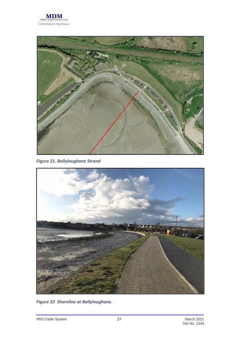
Figure 21. Ballyloughane Strand ..............................................................................27

IRIS Cable System 3 March 2021 Job No. 1334
Figure 22. Shoreline at Ballyloughane. ...................................................................27
Figure 23. Ordnance Survey Map: Scale 6" to 1 mile ...............................................28
Figure 24. Ordnance Survey Map: Scale 1/1000. ....................................................29
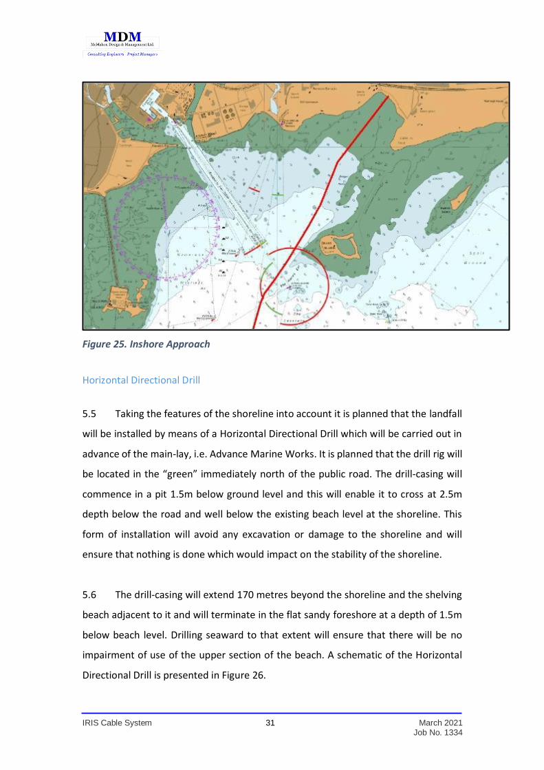
Figure 25. Inshore Approach ....................................................................................31
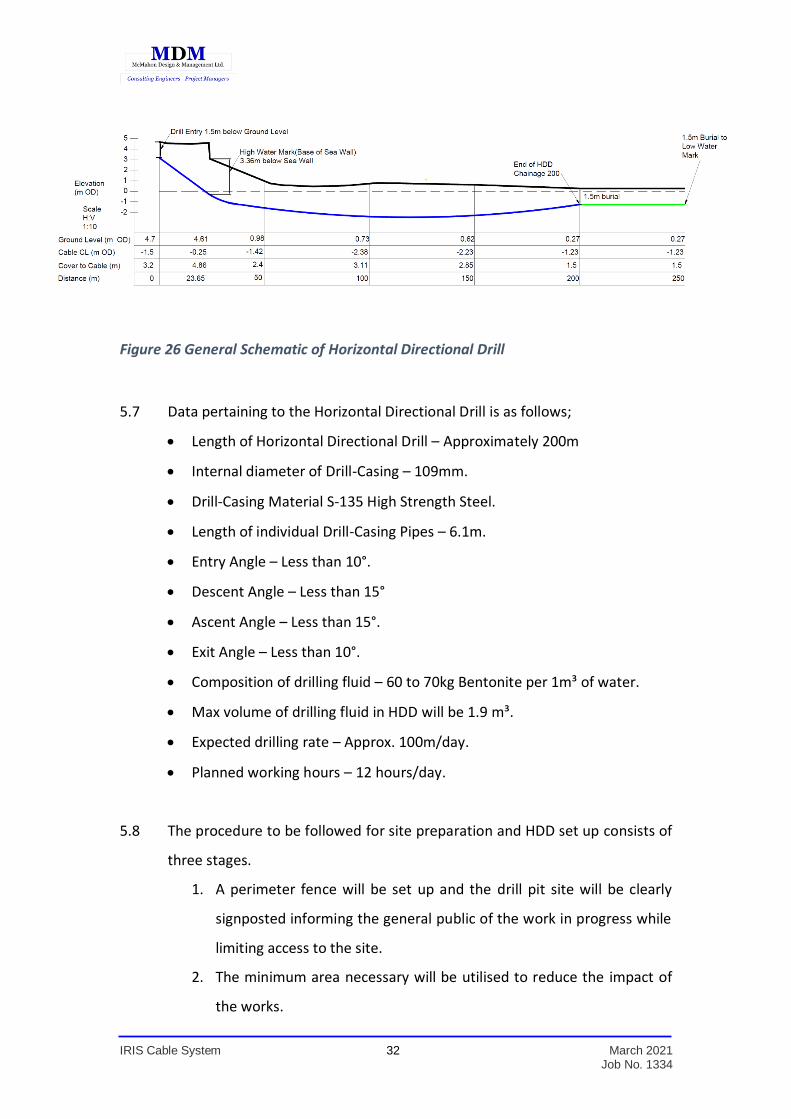
Figure 26. General Schematic of Horizontal Directional Drill ...................................32
Figure 27. Sandpiper Jetsled ....................................................................................36
Figure 28. Beach Access ...........................................................................................38
Figure 29. Offshore Cable Installation and Plough Burial. .......................................39
Figure 30. Commercial Fisheries Inshore .................................................................42
Figure 31. Aquaculture in Galway Bay .....................................................................43
Figure 32. Licence Blocks off the west and northwest of Ireland .............................45
Figure 33. Commercial Fisheries Offshore. .............................................................46
Figure 34. Shipping Traffic (AIS data, 2018) ............................................................47
IRIS Cable System 4 March 2021 Job No. 1334
1.0 INTRODUCTION
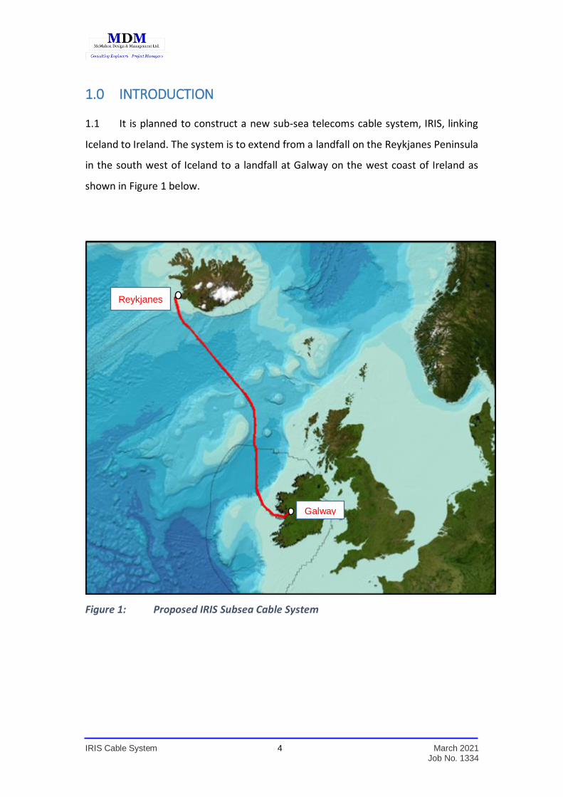
1.1 It is planned to construct a new sub-sea telecoms cable system, IRIS, linking
Iceland to Ireland. The system is to extend from a landfall on the Reykjanes Peninsula
in the south west of Iceland to a landfall at Galway on the west coast of Ireland as
shown in Figure 1 below.
Figure 1: Proposed IRIS Subsea Cable System
Galway
Reykjanes

IRIS Cable System 5 March 2021 Job No. 1334
1.2 The proposed project arises from discussions between Farice ehf (Ltd) and
DeepSea Fibre Networks Ltd. Farice ehf (Ltd) was founded in November 2002 by a
number of telecommunications companies in Iceland and the Faroe Islands as well as
the Icelandic State in order to build and operate the FARICE-1 submarine cable. That
cable was put into service in January 2004 and a second cable, DANICE, was put into
service in September 2009. The Icelandic state now has 100% of the shares under its
ownership and the company is the main provider of wholesale broadband capacity in
and out of Iceland.
1.3 The high-level programme for the project is as follows:
Submit Main-Lay Application: February 2021
Contracts for Main-Lay & Cable: March 2021
Shore-end Installation: April 2022
Main-Lay: May – August 2022
This is the proposed overall programme but may be subject to change
arising from the Licensing/Permitting process.
1.4 A cable route survey and Site Investigations have been carried out in the form
of geophysical survey (utilising acoustic remote sensing techniques such as
Multibeam echo sounder, Side scan sonar, Sub bottom profiler and non-acoustic
Marine magnetometer) with selective sampling of the seabed (geotechnical survey)
for ground truthing and assessment. The results of the survey, which was carried out
in September 2020, have been analysed and a draft preferred route corridor was
developed. An Appropriate Assessment screening report and stage 2 Natura Impact
Statement, an Ecological Impact Assessment Study and a Marine Archaeology and
Cultural Heritage Impact Assessment were also undertaken and, taking all factors into
IRIS Cable System 6 March 2021 Job No. 1334
account, a final Route Position List (RPL) has been developed in Irish Territorial Waters
and extending northwards to the EEZ boundary.
1.5 This planning report has been prepared by MDM Ltd and forms part of an
application for a Foreshore Licence for Cable Installation in Irish Territorial Waters.
The report presents a Route Position List indicating the centre line for the cable route
corridor within the Irish EEZ, an outline of the seabed conditions to be traversed, the
Appropriate Assessment screening report and stage 2 Natura Impact Statement, an
Ecological Impact Assessment Study and a Marine Archaeology and Cultural Heritage
Impact Assessment. It is accompanied by appropriate maps, diagrams and route
drawings.

IRIS Cable System 7 March 2021 Job No. 1334
2.0 BACKGROUND
2.1 The planned Route Corridor in Irish waters is based on the following:
Detailed Marine Survey and Site Investigations incorporating Bathymetry,
Side Scan Sonar, Multi-Beam Backscatter, Sub-Bottom Profile and
Magnetometer data.
Sea-bed Sediment and Bedform data for Galway Bay available under
licence via the Marine Institute
Landfall Features.
Galway Port Development Plan.
Admiralty Chart Data
Inventory of Wrecks.
Inventory of existing cables.
Inventory of marine installations and licence blocks.
Marine Archaeology and Cultural Heritage Impact Assessment.
AA screening & stage 2 Natura Impact Statement.
Ecological Impact Assessment.
Liaison with representatives of the local Fishing community.
Other data in the public domain.
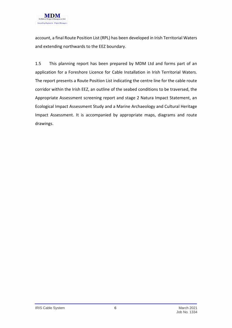
2.2 The cable is to be an industry-standard cable with the capability to transmit
high-speed data and voice via light wave through the optical fibres contained within
the core Unit Fibre Structure (UFS). The “IRIS” cable will have a total of 6 Fibre Pairs.
The cable will be double armoured in Irish waters and a cut-away section of the cable
is shown in Figure 2.
IRIS Cable System 8 March 2021 Job No. 1334
Figure 2: Typical Double Armour Cable Section
2.3 The UFS is the innermost element of the cable and consists of optical fibres
embedded in a buffer gel material inside a Polybutylene Terephthalate plastic tube.
The buffer gel is a thixotropic material that protects the optical fibres from shear
stresses associated with movement inside the tube. Ultra-high strength steel wires
are helically wrapped around the UFS and together they act as a pressure vessel
that protects the UFS from stresses up to and in excess of 100 MPa. The interstices
between the steel wires are filled with a hydrophobic elastomeric water-blocking
material which resists longitudinal water ingress. The SL design includes a
conductor to carry both system power and the cable monitoring and maintenance
signal. The power conductor is constructed by seam welding a copper tape around
the high-strength wires. A thin layer of ethylene-acrylic and copolymer plastic resin
and a thick layer of polyethylene insulating jacket are coextruded over the copper
sheath. The polyethylene jacket provides insulation, abrasion resistance and
corrosion protection.
Cable ID 35.9mm
IRIS Cable System 9 March 2021 Job No. 1334
2.4 The double armour, consisting of two layers of galvanised wire wrapped
around the cable, is coated with hot-blown petroleum asphalt and wound with
asphalt-soaked yarn. The finished DA Cable has an outer diameter of 35.9mm.
2.5 The cable will have Repeaters approximately 80km apart. These are “Optical
Amplifiers” whose primary purpose is to boost the optical signal along the route.
The copper conductors inside the cable power these Repeaters. The system line
current will be of the order of 1 amp. The capacity of the cable is between 15 to
18 Terabit’s per Fibre Pair. The deciding factor between 15 to 18 terabit’s is
dependent on the type and make of electronics that is installed at each Cable
Landing Station (CLS).
IRIS Cable System 10 March 2021 Job No. 1334
3.0 THE PLANNED ROUTE
The General Route in Irish Territorial Waters
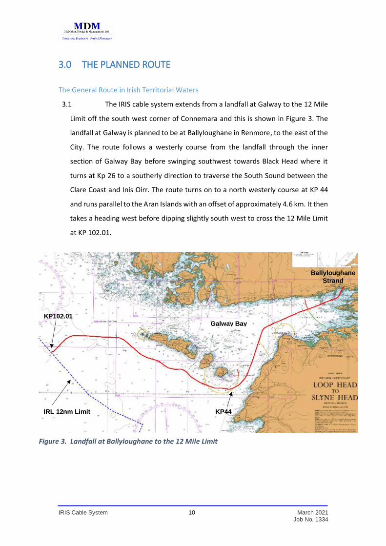
3.1 The IRIS cable system extends from a landfall at Galway to the 12 Mile
Limit off the south west corner of Connemara and this is shown in Figure 3. The
landfall at Galway is planned to be at Ballyloughane in Renmore, to the east of the
City. The route follows a westerly course from the landfall through the inner
section of Galway Bay before swinging southwest towards Black Head where it
turns at Kp 26 to a southerly direction to traverse the South Sound between the
Clare Coast and Inis Oirr. The route turns on to a north westerly course at KP 44
and runs parallel to the Aran Islands with an offset of approximately 4.6 km. It then
takes a heading west before dipping slightly south west to cross the 12 Mile Limit
at KP 102.01.
Ballyloughane
Strand
IRL 12nm Limit
Galway Bay KP102.01
KP44
Figure 3. Landfall at Ballyloughane to the 12 Mile Limit
IRIS Cable System 11 March 2021 Job No. 1334
The General Route in Irish EEZ Waters
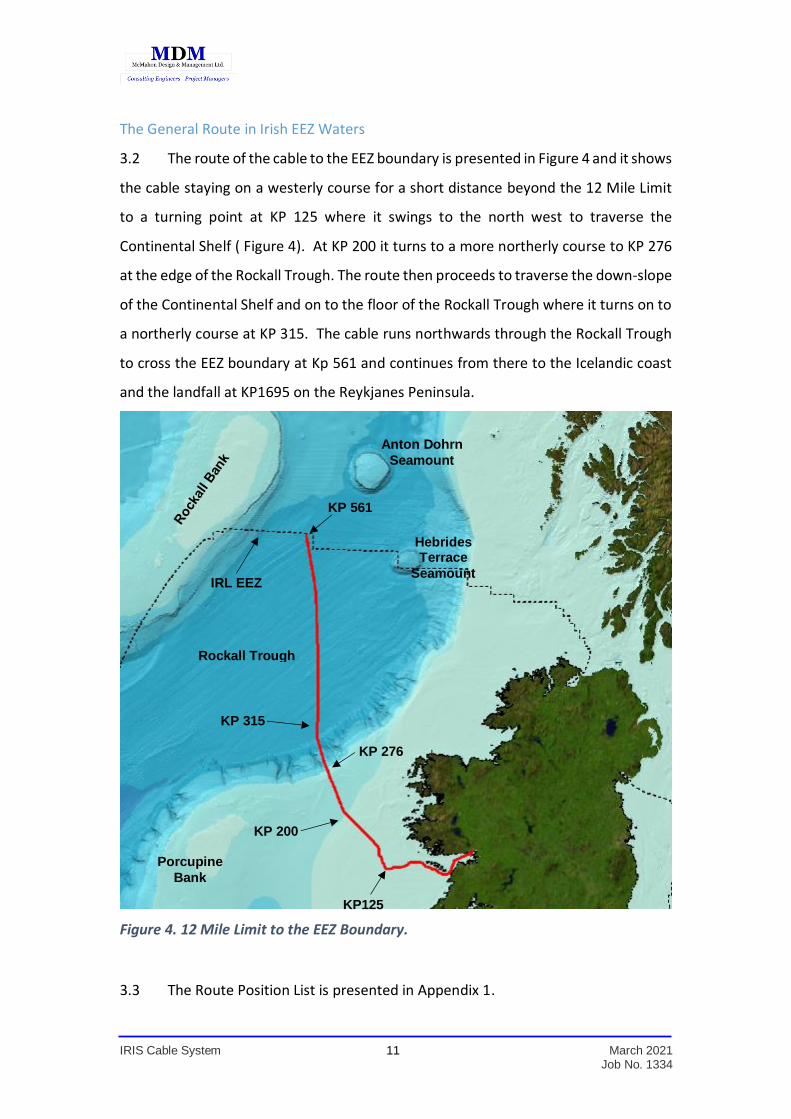
3.2 The route of the cable to the EEZ boundary is presented in Figure 4 and it shows
the cable staying on a westerly course for a short distance beyond the 12 Mile Limit
to a turning point at KP 125 where it swings to the north west to traverse the
Continental Shelf ( Figure 4). At KP 200 it turns to a more northerly course to KP 276
at the edge of the Rockall Trough. The route then proceeds to traverse the down-slope
of the Continental Shelf and on to the floor of the Rockall Trough where it turns on to
a northerly course at KP 315. The cable runs northwards through the Rockall Trough
to cross the EEZ boundary at Kp 561 and continues from there to the Icelandic coast
and the landfall at KP1695 on the Reykjanes Peninsula.
Figure 4. 12 Mile Limit to the EEZ Boundary.
3.3 The Route Position List is presented in Appendix 1.
Rockall Trough
Porcupine
Bank
Hebrides Terrace
Seamount
Anton Dohrn
Seamount
KP125
KP 200
KP 276
KP 315
KP 561
IRL EEZ
IRIS Cable System 12 March 2021 Job No. 1334
Specific Sections of Route
3.4 Specific sections of the route from Galway to the EEZ boundary, off the north
west coast, are as follows;
Landfall at Ballyloughane to Black Head
The South Sound
The Aran Islands
The Aran Islands to the 12 Mile Limit
12 Mile Limit to the EEZ Boundary
3.5 The distance from the landfall at Ballyloughane to the 12 Mile Limit is 102
kilometres and the overall distance to the EEZ boundary is 561 kilometres.
Ballyloughane to Black Head
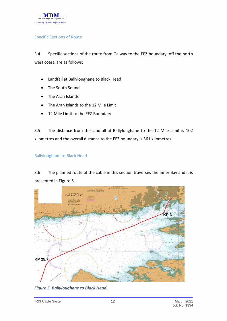
3.6 The planned route of the cable in this section traverses the Inner Bay and it is
presented in Figure 5.
Figure 5. Ballyloughane to Black Head.
KP 3
KP 25.7
IRIS Cable System 13 March 2021 Job No. 1334
3.7 It can be seen from Figure 5 that, as it leaves Ballyloughane, the route of the
cable proceeds to the west of Hare Island, avoiding traversing the existing and
proposed future navigation channels of Galway Port. The route continues in a general
west south west heading, carefully diverting around zones of ecological importance
and navigation hazards such as the shallows of the Tawin and Margaretta shoals and
the Henry ledges.
3.8 Once past the Margaretta shoals, the cable route traverses the Bay in a south
westerly direction, then turning at KP 25.7 near Black Head to proceed southwards
through the South Sound.
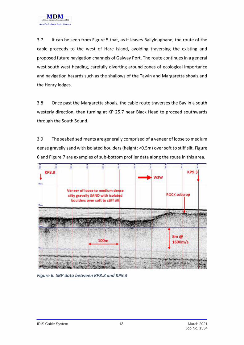
3.9 The seabed sediments are generally comprised of a veneer of loose to medium
dense gravelly sand with isolated boulders (height: <0.5m) over soft to stiff silt. Figure
6 and Figure 7 are examples of sub-bottom profiler data along the route in this area.
Figure 6. SBP data between KP8.8 and KP9.3
IRIS Cable System 14 March 2021 Job No. 1334
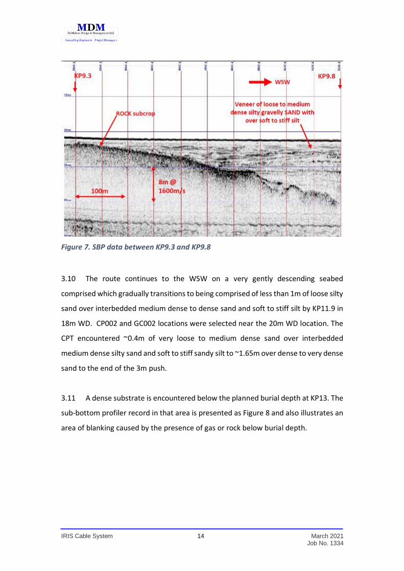
Figure 7. SBP data between KP9.3 and KP9.8
3.10 The route continues to the WSW on a very gently descending seabed
comprised which gradually transitions to being comprised of less than 1m of loose silty
sand over interbedded medium dense to dense sand and soft to stiff silt by KP11.9 in
18m WD. CP002 and GC002 locations were selected near the 20m WD location. The
CPT encountered ~0.4m of very loose to medium dense sand over interbedded
medium dense silty sand and soft to stiff sandy silt to ~1.65m over dense to very dense
sand to the end of the 3m push.
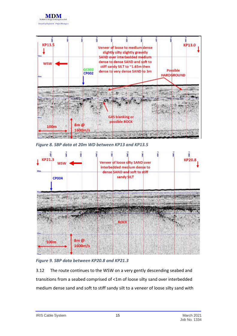
3.11 A dense substrate is encountered below the planned burial depth at KP13. The
sub-bottom profiler record in that area is presented as Figure 8 and also illustrates an
area of blanking caused by the presence of gas or rock below burial depth.
IRIS Cable System 15 March 2021 Job No. 1334
Figure 8. SBP data at 20m WD between KP13 and KP13.5
Figure 9. SBP data between KP20.8 and KP21.3
3.12 The route continues to the WSW on a very gently descending seabed and
transitions from a seabed comprised of <1m of loose silty sand over interbedded
medium dense sand and soft to stiff sandy silt to a veneer of loose silty sand with
IRIS Cable System 16 March 2021 Job No. 1334
poorly developed megaripples over <1.5m of soft to stiff sandy silt over interbedded
medium dense to dense sand and firm to stiff sandy silt around KP20.8 in 31m WD.
The South Sound
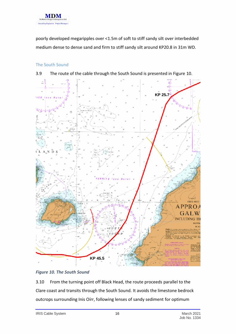
3.9 The route of the cable through the South Sound is presented in Figure 10.
Figure 10. The South Sound
3.10 From the turning point off Black Head, the route proceeds parallel to the
Clare coast and transits through the South Sound. It avoids the limestone bedrock
outcrops surrounding Inis Oírr, following lenses of sandy sediment for optimum
KP 25.7
KP 45.5
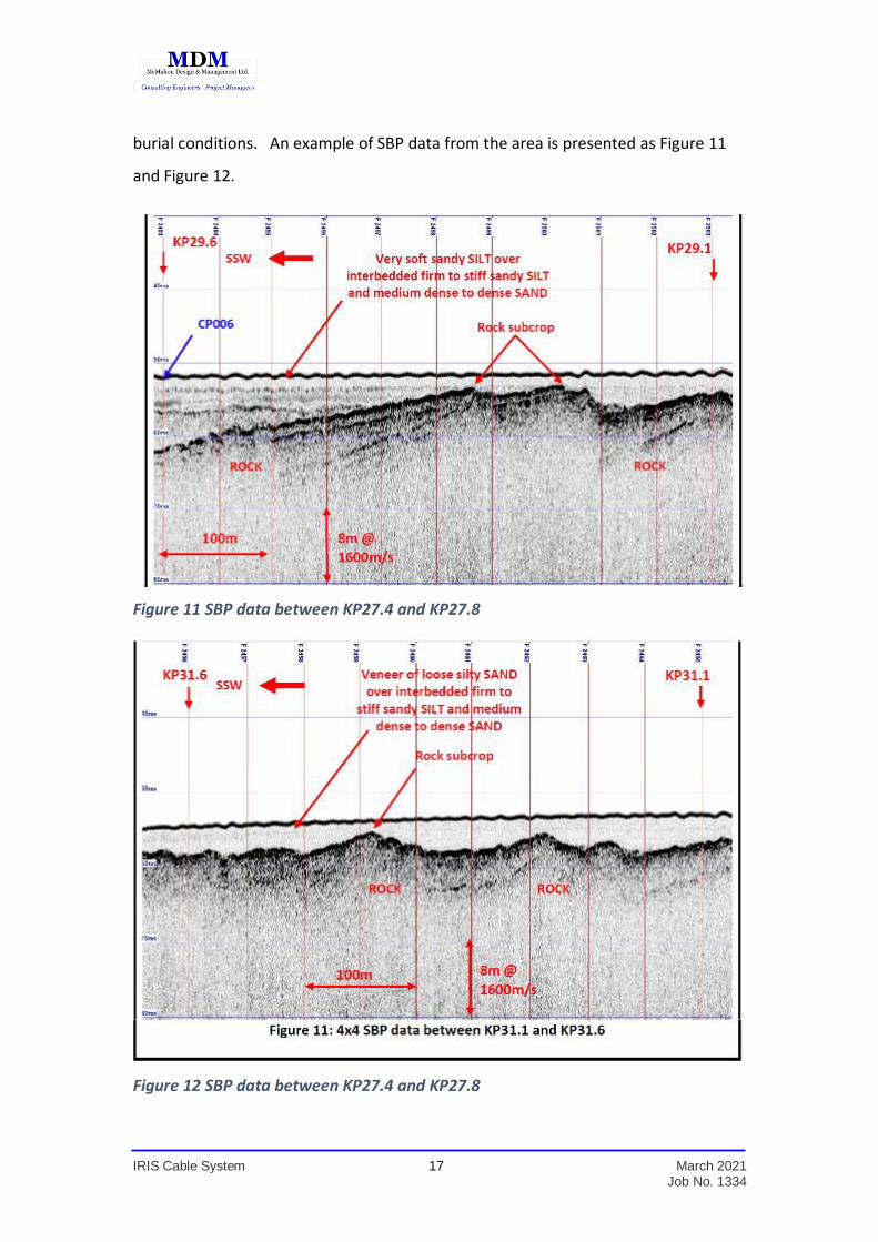
IRIS Cable System 17 March 2021 Job No. 1334
burial conditions. An example of SBP data from the area is presented as Figure 11
and Figure 12.
Figure 11 SBP data between KP27.4 and KP27.8
Figure 12 SBP data between KP27.4 and KP27.8

IRIS Cable System 18 March 2021 Job No. 1334
3.11 Near KP32 the seabed is consistent with the previous section, but an area of
low relief ROCK outcrop is delineated to W of the route near the edge of the corridor
as illustrated in Figure 13.
Figure 13 SSS showing low rock to north of route at KP32.
3.12 There is a curving linear depression/channel feature of less than 0.5m in
depth near KP38.4. This area is between Inisheer Island to just north of Doolin Point.
Currents here would be expected to increase because of the constriction between
the island and the mainland.
3.13 The route continues to the SSW avoiding ROCK outcrop and subcrop. The
seabed appears featureless and seabed slopes are gentle but subcrop is still
IRIS Cable System 19 March 2021 Job No. 1334
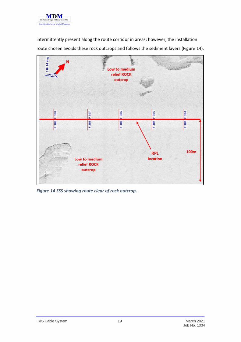
intermittently present along the route corridor in areas; however, the installation
route chosen avoids these rock outcrops and follows the sediment layers (Figure 14).
Figure 14 SSS showing route clear of rock outcrop.
IRIS Cable System 20 March 2021 Job No. 1334
The Aran Islands
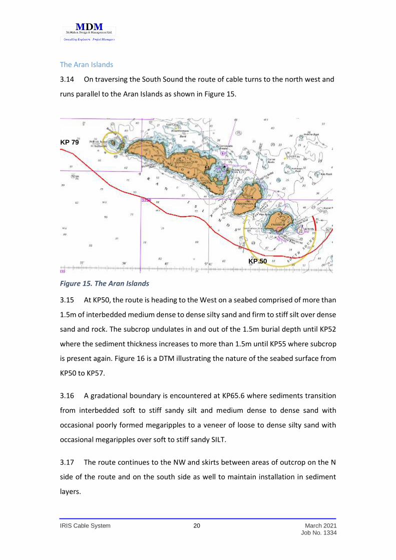
3.14 On traversing the South Sound the route of cable turns to the north west and
runs parallel to the Aran Islands as shown in Figure 15.
Figure 15. The Aran Islands
3.15 At KP50, the route is heading to the West on a seabed comprised of more than
1.5m of interbedded medium dense to dense silty sand and firm to stiff silt over dense
sand and rock. The subcrop undulates in and out of the 1.5m burial depth until KP52
where the sediment thickness increases to more than 1.5m until KP55 where subcrop
is present again. Figure 16 is a DTM illustrating the nature of the seabed surface from
KP50 to KP57.
3.16 A gradational boundary is encountered at KP65.6 where sediments transition
from interbedded soft to stiff sandy silt and medium dense to dense sand with
occasional poorly formed megaripples to a veneer of loose to dense silty sand with
occasional megaripples over soft to stiff sandy SILT.
3.17 The route continues to the NW and skirts between areas of outcrop on the N
side of the route and on the south side as well to maintain installation in sediment
layers.
KP 50
KP 79
IRIS Cable System 21 March 2021 Job No. 1334
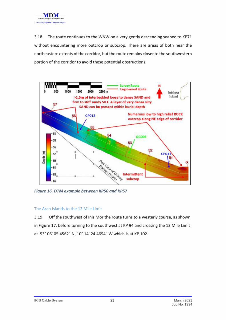
3.18 The route continues to the WNW on a very gently descending seabed to KP71
without encountering more outcrop or subcrop. There are areas of both near the
northeastern extents of the corridor, but the route remains closer to the southwestern
portion of the corridor to avoid these potential obstructions.
Figure 16. DTM example between KP50 and KP57
The Aran Islands to the 12 Mile Limit
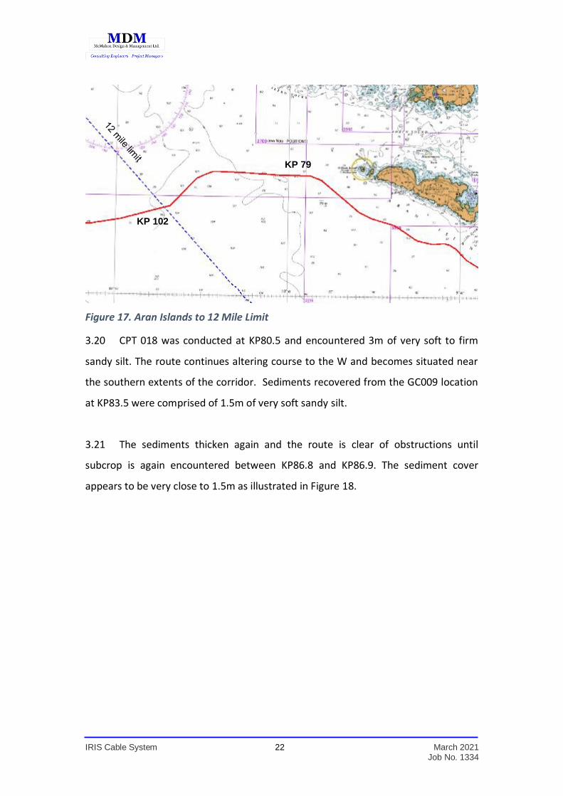
3.19 Off the southwest of Inis Mor the route turns to a westerly course, as shown
in Figure 17, before turning to the southwest at KP 94 and crossing the 12 Mile Limit
at 53° 06' 05.4562" N, 10° 14' 24.4694" W which is at KP 102.
IRIS Cable System 22 March 2021 Job No. 1334
Figure 17. Aran Islands to 12 Mile Limit
3.20 CPT 018 was conducted at KP80.5 and encountered 3m of very soft to firm
sandy silt. The route continues altering course to the W and becomes situated near
the southern extents of the corridor. Sediments recovered from the GC009 location
at KP83.5 were comprised of 1.5m of very soft sandy silt.
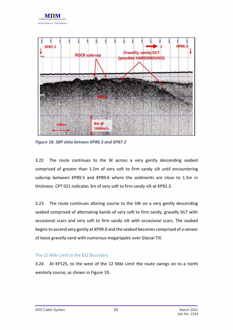
3.21 The sediments thicken again and the route is clear of obstructions until
subcrop is again encountered between KP86.8 and KP86.9. The sediment cover
appears to be very close to 1.5m as illustrated in Figure 18.
KP 102
KP 79
IRIS Cable System 23 March 2021 Job No. 1334
Figure 18. SBP data betwen KP86.3 and KP87.2
3.22 The route continues to the W across a very gently descending seabed
comprised of greater than 1.5m of very soft to firm sandy silt until encountering
subcrop between KP89.5 and KP89.6 where the sediments are close to 1.5m in
thickness. CPT 021 indicates 3m of very soft to firm sandy silt at KP92.3.
3.23 The route continues altering course to the SW on a very gently descending
seabed comprised of alternating bands of very soft to firm sandy, gravelly SILT with
occasional scars and very soft to firm sandy silt with occasional scars. The seabed
begins to ascend very gently at KP99.0 and the seabed becomes comprised of a veneer
of loose gravelly sand with numerous megaripples over Glacial Till.
The 12 Mile Limit to the EEZ Boundary
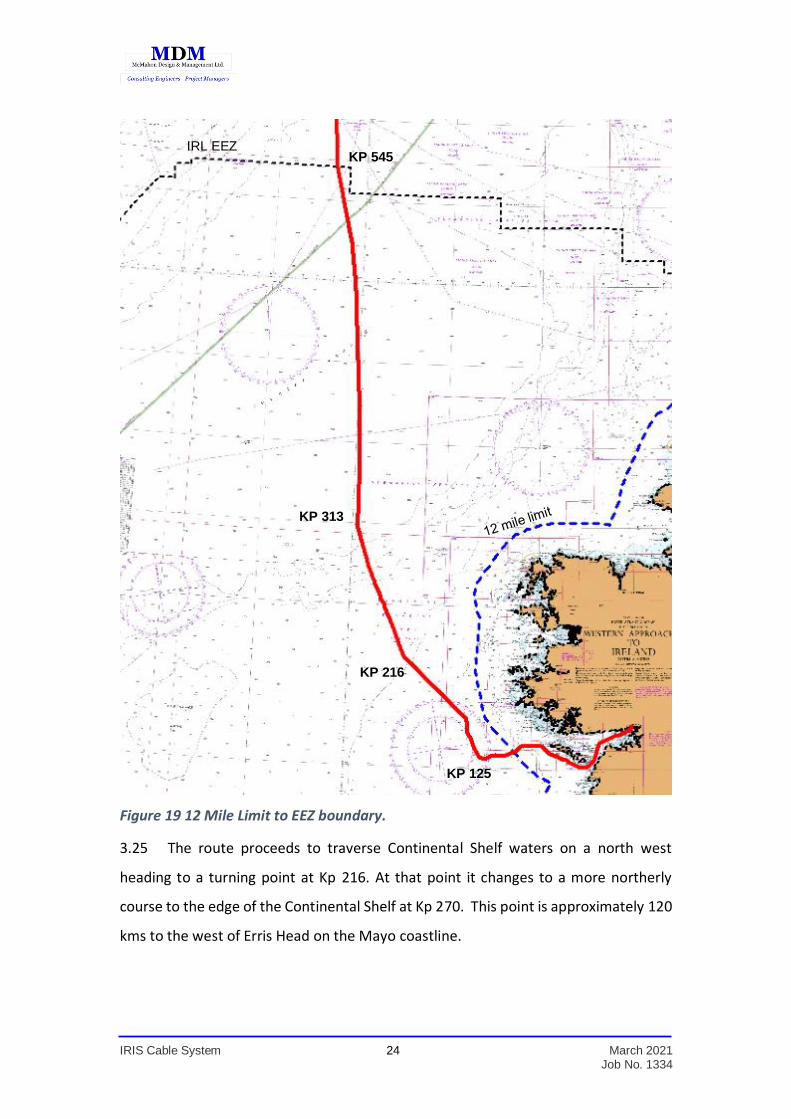
3.24 At KP125, to the west of the 12 Mile Limit the route swings on to a north
westerly course, as shown in Figure 19.
IRIS Cable System 24 March 2021 Job No. 1334
Figure 19 12 Mile Limit to EEZ boundary.
3.25 The route proceeds to traverse Continental Shelf waters on a north west
heading to a turning point at Kp 216. At that point it changes to a more northerly
course to the edge of the Continental Shelf at Kp 270. This point is approximately 120
kms to the west of Erris Head on the Mayo coastline.
IRL EEZ KP 545
KP 125
KP 216
KP 313

IRIS Cable System 25 March 2021 Job No. 1334
3.26 The route then drops into the deep waters of the Rockall Trough at Kp 285 and
continues to a turning point at Kp 313 where it turns to a direct northerly heading
through the Rockall Trough to cross the Irish EEZ boundary at Kp 545.
IRIS Cable System 26 March 2021 Job No. 1334
4.0 LANDFALL AT BALLYLOUGHANE STRAND
The Landfall at Ballyloughane Strand
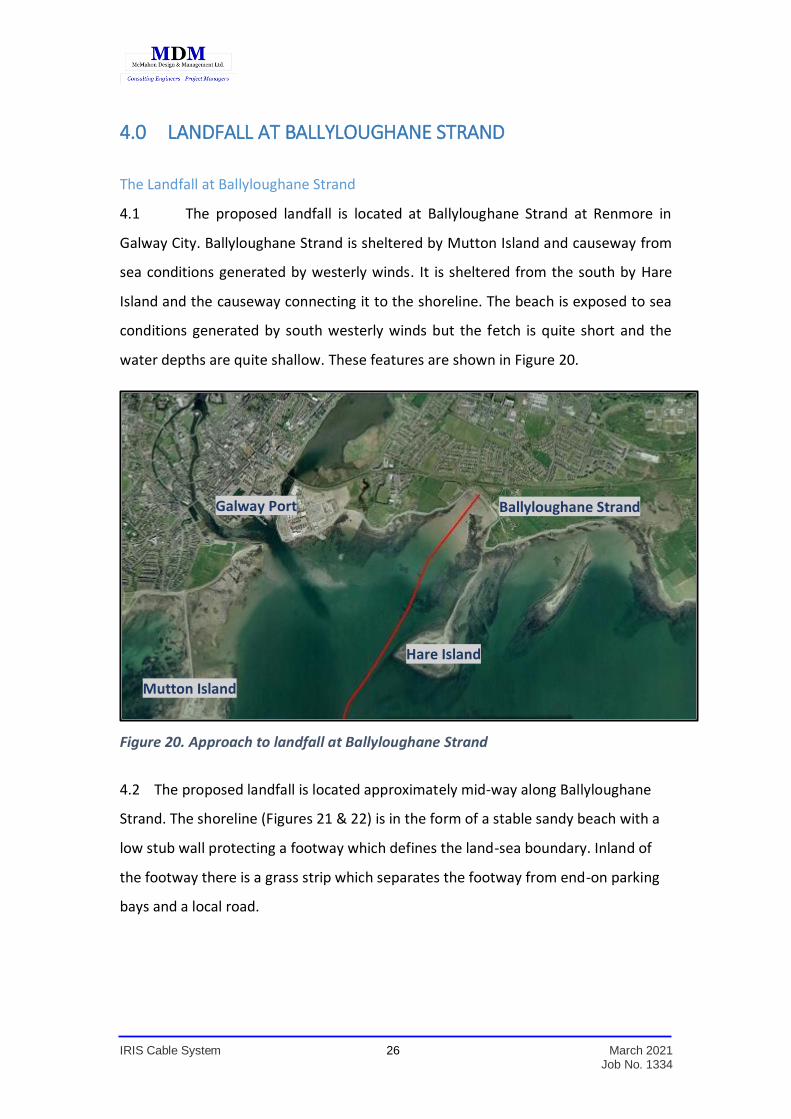
4.1 The proposed landfall is located at Ballyloughane Strand at Renmore in
Galway City. Ballyloughane Strand is sheltered by Mutton Island and causeway from
sea conditions generated by westerly winds. It is sheltered from the south by Hare
Island and the causeway connecting it to the shoreline. The beach is exposed to sea
conditions generated by south westerly winds but the fetch is quite short and the
water depths are quite shallow. These features are shown in Figure 20.
Figure 20. Approach to landfall at Ballyloughane Strand
4.2 The proposed landfall is located approximately mid-way along Ballyloughane
Strand. The shoreline (Figures 21 & 22) is in the form of a stable sandy beach with a
low stub wall protecting a footway which defines the land-sea boundary. Inland of
the footway there is a grass strip which separates the footway from end-on parking
bays and a local road.
Ballyloughane Strand
Mutton Island
Hare Island
Galway Port
IRIS Cable System 27 March 2021 Job No. 1334
Figure 21. Ballyloughane Strand
Figure 22 Shoreline at Ballyloughane.
IRIS Cable System 28 March 2021 Job No. 1334
Ordnance Survey Maps
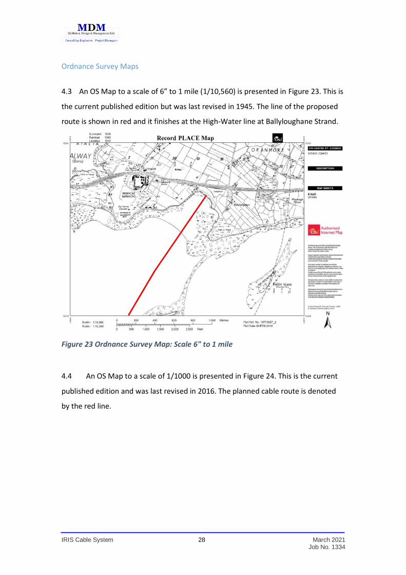
4.3 An OS Map to a scale of 6” to 1 mile (1/10,560) is presented in Figure 23. This is
the current published edition but was last revised in 1945. The line of the proposed
route is shown in red and it finishes at the High-Water line at Ballyloughane Strand.
Figure 23 Ordnance Survey Map: Scale 6" to 1 mile
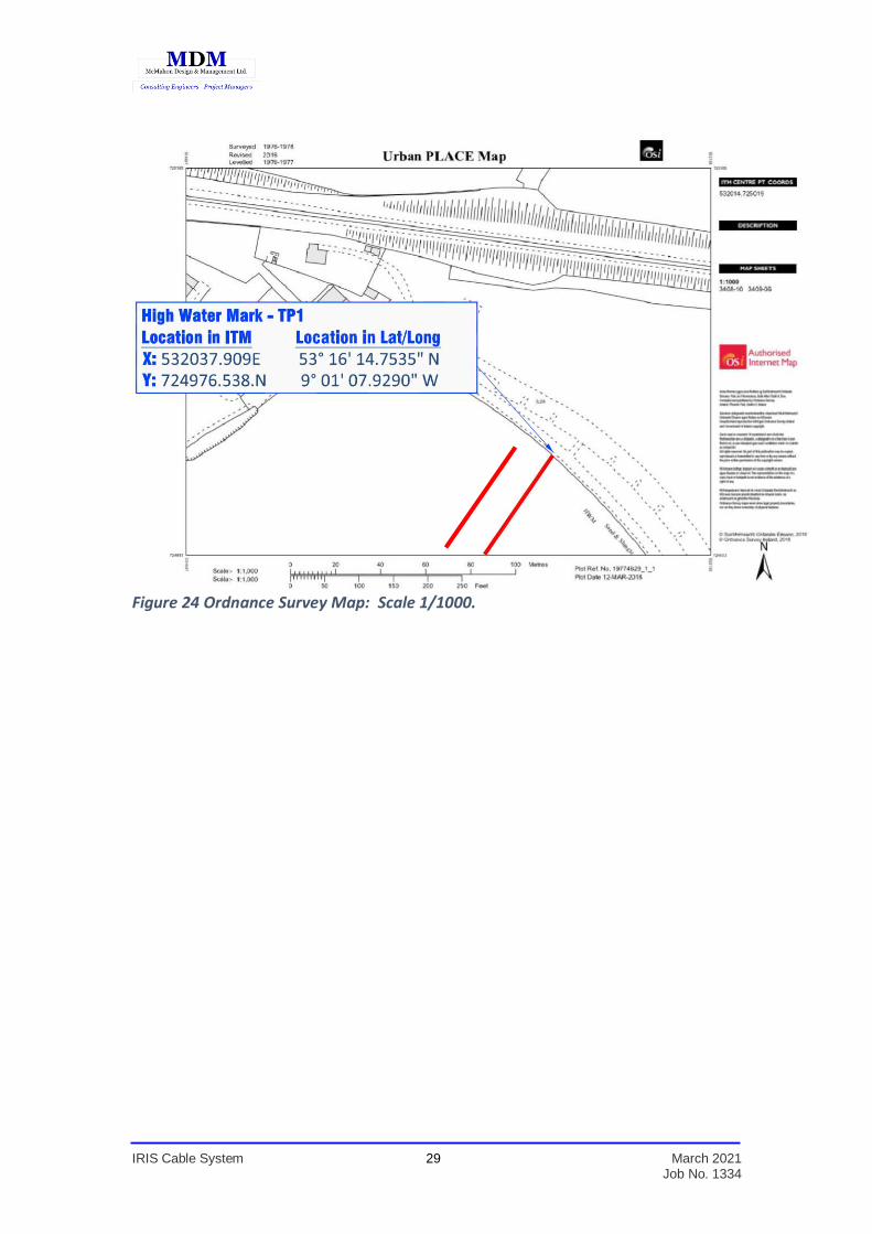
4.4 An OS Map to a scale of 1/1000 is presented in Figure 24. This is the current
published edition and was last revised in 2016. The planned cable route is denoted
by the red line.
IRIS Cable System 29 March 2021 Job No. 1334
Figure 24 Ordnance Survey Map: Scale 1/1000.
IRIS Cable System 30 March 2021 Job No. 1334
5.0 SUBSEA CABLE INSTALLATION
5.1 The cable system is comprised of a number of specific installations as follows;
The Landfall at Galway (Ballyloughane Strand)
Cable Installation on the Beach
Subsea Cable Installation
Inshore Approach
5.2 The inshore approach to the landfall is shown in Figure 25 on an Admiralty
Chart base. The beach is gently sloping and extends over a distance of 560 metres to
the Low Water Line (Mean Springs).
5.3 Seaward of the Low Water Line the seabed continues its gentle slope to cross
the 5 metre water depth contour at 1.43 kilometres metres from the shore-line. The
gently sloping sea-be extends for a further 4.3 kilometres before it reaches the 10m
water depth contour.
5.4 The line of the planned route on the approach to the landfall has been developed
and agreed in consultation with the Harbour Master at Galway Port with respect to
navigation and future expansion of the port.
IRIS Cable System 31 March 2021 Job No. 1334
Figure 25. Inshore Approach
Horizontal Directional Drill
5.5 Taking the features of the shoreline into account it is planned that the landfall
will be installed by means of a Horizontal Directional Drill which will be carried out in
advance of the main-lay, i.e. Advance Marine Works. It is planned that the drill rig will
be located in the “green” immediately north of the public road. The drill-casing will
commence in a pit 1.5m below ground level and this will enable it to cross at 2.5m
depth below the road and well below the existing beach level at the shoreline. This
form of installation will avoid any excavation or damage to the shoreline and will
ensure that nothing is done which would impact on the stability of the shoreline.
5.6 The drill-casing will extend 170 metres beyond the shoreline and the shelving
beach adjacent to it and will terminate in the flat sandy foreshore at a depth of 1.5m
below beach level. Drilling seaward to that extent will ensure that there will be no
impairment of use of the upper section of the beach. A schematic of the Horizontal
Directional Drill is presented in Figure 26.
IRIS Cable System 32 March 2021 Job No. 1334
Figure 26 General Schematic of Horizontal Directional Drill
5.7 Data pertaining to the Horizontal Directional Drill is as follows;
Length of Horizontal Directional Drill – Approximately 200m
Internal diameter of Drill-Casing – 109mm.
Drill-Casing Material S-135 High Strength Steel.
Length of individual Drill-Casing Pipes – 6.1m.
Entry Angle – Less than 10°.
Descent Angle – Less than 15°
Ascent Angle – Less than 15°.
Exit Angle – Less than 10°.
Composition of drilling fluid – 60 to 70kg Bentonite per 1m³ of water.
Max volume of drilling fluid in HDD will be 1.9 m³.
Expected drilling rate – Approx. 100m/day.
Planned working hours – 12 hours/day.
5.8 The procedure to be followed for site preparation and HDD set up consists of
three stages.
1. A perimeter fence will be set up and the drill pit site will be clearly
signposted informing the general public of the work in progress while
limiting access to the site.
2. The minimum area necessary will be utilised to reduce the impact of
the works.

IRIS Cable System 33 March 2021 Job No. 1334
3. All the equipment necessary for the drill pit and drill rig installation will
be transported to the site pending the excavation of the pit and the
final positioning of all necessary tools and equipment.
4. The pit will be excavated and lined with geotextile and polyethylene
sheet to prevent any seepage of drilling fluids into the surrounding soil.
5.9 The drilling process will be closely monitored and logs will be kept over the
entire duration of the operations. The drill design will be followed so that the
achievable drill will be within acceptable tolerances. The bore alignment will follow
the reference alignment shown on the plans and will be accurate to within the
following tolerances:
The bore entry angle will not exceed fifteen (15) degrees
Installation of the horizontal directional drill will be within 1 m of the
centreline of the bore indicated on the drawings at the bore entry.
Installation of the horizontal directional drill will be within 3 m of the
centreline of the bore indicated on the drawings for the entire length
of the bore.
The bore exit angle will be maintained at ten (10) degrees or flatter.
5.10 The method employed to monitor the progress of the HDD necessitates the
use of a wire-line connected transmitter system in order to provide sufficient data so
that the drill bit’s relative position is recorded in real-time throughout the entire
drilling operation. A non-magnetic sonde will be installed on an adaptor casing
following the mud motor attachment in the bore and wire-lined back to the HDD Rig.
This sonde is responsible for transmitting a signal to provide real-time information
regarding the drill bit’s azimuth, vertical distance from the receiver (which is
translated as depth) as well as its coordinates (Latitude – Longitude). All information
transmitted is constantly displayed in a remote monitor mounted on the HDD machine
so that the operator is always aware of the precision of the bore’s progress.
IRIS Cable System 34 March 2021 Job No. 1334
5.11 Bentonite is commonly used as drilling mud to lubricate and cool cutting tools,
to remove cuttings and help prevent blowouts. Bentonite is a ground naturally
occurring clay. It is inorganic, non-toxic and non-irritating. It has a specific gravity of
approximately 2.4 and comes in the form of a grey powder. It expands when wet and,
when mixed with water at a concentration of the order of 60-70kg of bentonite
powder per m³ of water, it takes on the characteristics of a gel. Bentonite is widely
used in the construction industry as a drilling fluid, as a lining for the base of landfills
and for the construction of curtain walls to waterproof below-grade excavations.
5.12 It is planned to clean out and flush the steel drill casing with water when it
reaches its target length and a temporary pit will then be excavated at the exit
location. Whilst it is anticipated that no bentonite will escape from the HDD bore
which will be 1.5 m below the sand surface, any residue which may escape will be very
little and will be contained in the exit pit.
5.13 All necessary precautions shall be put in place to protect foreshore users in
accordance with relevant Health and Safety Legislation with temporary fencing,
barriers and signage in place around the location of the exit pit. The minimum area
necessary will be utilised to reduce the impact of the works. Excavation and backfill of
the reception pit will involve the use of a tracked excavator or JCB on the beach for a
short period.
5.14 The volume of fluids and cuttings produced during the HDD process will be
removed from the on-shore drilling pit at regular intervals by way of sludge pumps
and sent to the recycling unit positioned alongside the drilling pit. Solids can be
optically assessed with accuracy after the fluid turbidity clears and the volume of fluids
can be also calculated. All residue will be disposed of in accordance with the
requirements of Galway City Council.
5.15 Once the HDD pipe is installed, it will be tested through its entire length to
prove the minimum internal diameter required and to ensure that no abnormalities,
IRIS Cable System 35 March 2021 Job No. 1334
which may affect the future cable landing, are existent. After the pipe inspection, a
messenger line (3/8” wire rope) will be installed and a cap will be fitted to prevent the
ingress of any sediment and/or debris.
Site Restoration
5.16 On completion of the HDD Works, the site will be restored to its
prior condition. All materials and equipment will be removed and the site area will be
cleaned and reinstated to its original condition. This will include the following:
Remove all debris and project-related material from the site at the
completion of the work.
Remove of all evidence of machinery presence and reinstatement of
the ground to its original condition.
Replant any and all vegetation damaged during the drilling operations.
Repair any damage to structures such as kerbs, fences, walls, gates, etc.
Beach Manhole & Ocean Ground Bed
5.17 The beach manhole is to be constructed onshore in the grassed area east of
the road at Ballyloughane, above the High Water Mark and outside the Foreshore
Limits. The Beach Manhole will be 3m long x 2m wide x 2m deep and is to be
constructed in reinforced concrete. Only the manhole cover will be visible at the
surface once the construction is complete. An ocean ground bed is a set of electrodes
which provides the return path for the electrical circuit that powers the repeaters
(amplifiers) in the submarine cable system. The ocean ground bed is typically buried
at least 2m below ground level. The plan dimensions of the ground bed will be 6m in
length and 1m in width – it is effectively a 6m long trench. This will be covered and the
ground reinstated.
IRIS Cable System 36 March 2021 Job No. 1334
Inshore Cable Installation
5.18 The cable installation from the end of the HDD out to the low water line will
be installed at low tide. The cable will be floated ashore from a Shallow-Draft Lay
Vessel using rigid inflatable boats (ribs) and buoys at high tide. Once the tide ebbs, the
end of the HDD duct will be exposed and the cable will be inserted in the HDD duct
and pulled from there into the Beach Manhole where it will be secured.
5.19 The section of cable from the end on the HDD to the low water line on the
intertidal will then be trenched to a target depth of 1.5m on a receding tide. Trenching
beyond the low water line will be achieved by the Shallow-Draft Lay Vessel with an
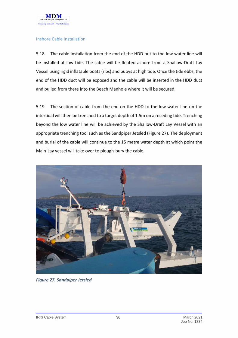
appropriate trenching tool such as the Sandpiper Jetsled (Figure 27). The deployment
and burial of the cable will continue to the 15 metre water depth at which point the
Main-Lay vessel will take over to plough-bury the cable.
Figure 27. Sandpiper Jetsled
IRIS Cable System 37 March 2021 Job No. 1334
Beach / Foreshore Access 5.20 There will be a requirement for equipment access to the beach / foreshore for;
Excavation and backfill of an exit pit at the end of the Horizontal
Directional Drill.
Pulling the cable ashore.
Installation of the cable from the end of the Horizontal Directional
Drill out to the Low Water Line.
5.21 The equipment will involve tracked excavators for the pit at the end of the
Horizontal Directional Drill and for pulling the cable ashore.
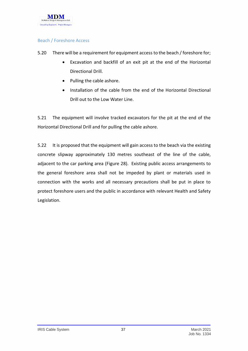
5.22 It is proposed that the equipment will gain access to the beach via the existing
concrete slipway approximately 130 metres southeast of the line of the cable,
adjacent to the car parking area (Figure 28). Existing public access arrangements to
the general foreshore area shall not be impeded by plant or materials used in
connection with the works and all necessary precautions shall be put in place to
protect foreshore users and the public in accordance with relevant Health and Safety
Legislation.
IRIS Cable System 38 March 2021 Job No. 1334
Figure 28. Beach Access
Offshore Cable Installation
5.23 A Pre-Lay Grapnel Run (PLGR) will be undertaken prior to commencement of
Main-Lay. This activity is to ensure that the planned line of the cable is clear of seabed
debris which may include chains, steel cables, anchors, nets etc. The swathe of the
grapnel is less than 1 metre wide and there will be minimal disturbance of the sea-bed
during the debris clearance operation. All debris recovered from the sea-bed will be
hauled on board and subsequently disposed of onshore in a safe and environmentally
approved manner. The PLGR vessel will use a DGPS positioning system. The route
followed by the PLGR will be as close as practicable to the selected Route Position List
and always within the swathe of the route survey.
Cable Installation on the Continental Shelf
5.24 The Main Lay vessel will pick up the end of the cable from the Inshore Section
at the 15 metre water depth and this will then be jointed to the main cable on board
IRIS Cable System 39 March 2021 Job No. 1334
the Main Lay Vessel. The jointing process takes approximately 18-24 hours to
complete including tests of the cable system. The Main Lay Vessel will then proceed
to deploy and bury the cable in the seabed using a sea-plough. The sea-plough is
towed by the Main Lay Vessel and is designed to bury the cable at a depth such that
the cable will be secure from fishing activities.
5.25 The plough uses a minimally invasive plough-share to create a furrow in the
seabed approximately 750mm in width. As the plough moves forward the cable is
placed in the bottom of the furrow which backfills with the natural movement of
sediment on the seafloor.
5.26 Typical ploughing speed is generally of the order of 0.5 knots and is dependent
on the stiffness of the seabed sediment. There is no significant noise generation during
ploughing operations. Cable installation by plough produces only a minor plume of
suspension of seabed sediments in the water column and this is transient and localised
due to the nature of the ploughing and natural backfill activities.
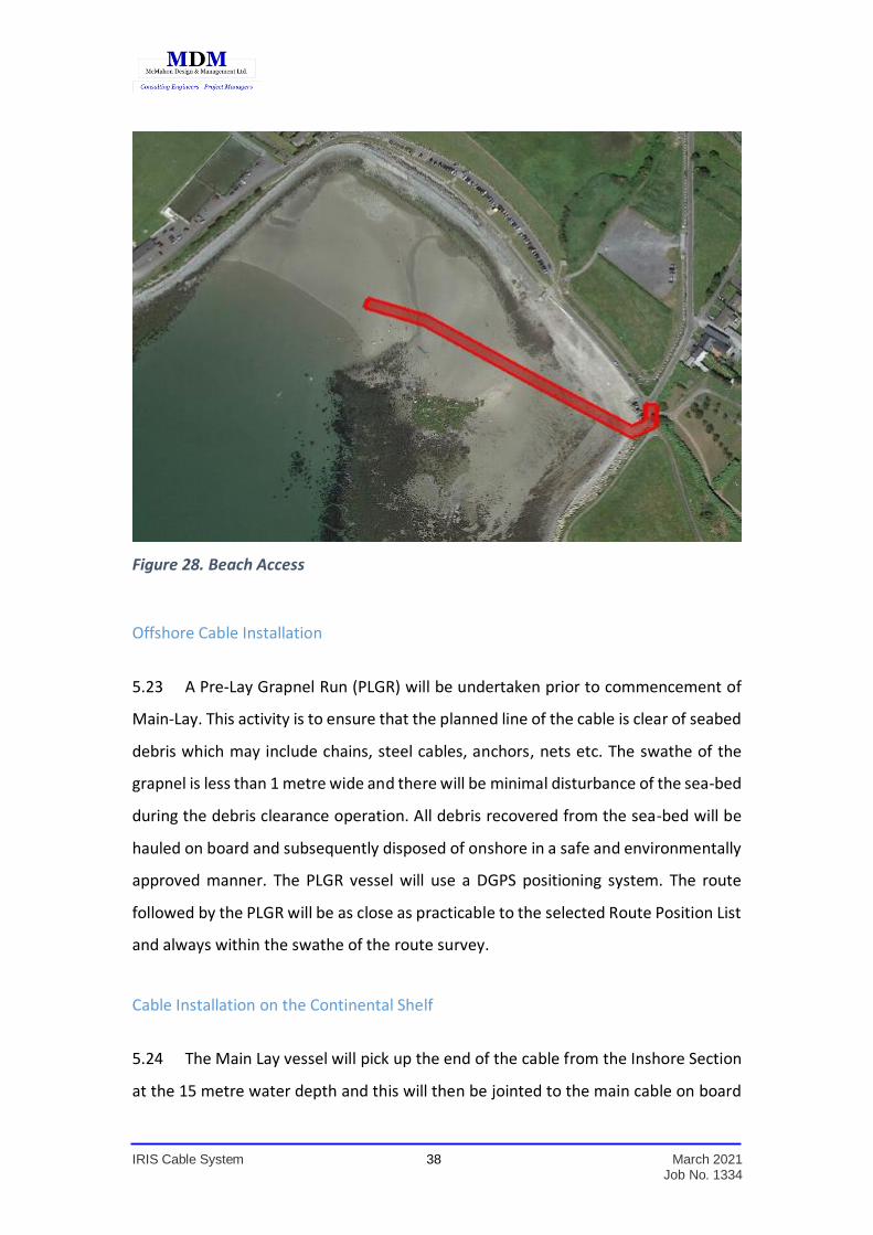
5.27 A sketch which illustrates the Main Lay cable installation is presented in Figure
29.
5.28 The target burial depth for the IRIS cable systems is 1.5 metres. In areas of stiff
soil, the actual burial depth may be reduced but is planned to be still at a depth which
will be protect the cable from fishing operations and not less than 0.7 to 0.9 metres.
Figure 29. Offshore Cable Installation and Plough Burial.
IRIS Cable System 40 March 2021 Job No. 1334
Post Lay Operations
5.29 Following main lay operations, post-lay inspection and burial may be carried
out in certain areas to inspect the proper laying and burial of the cable in the seabed.
A post-lay burial operation may be performed in order to supplement the burial
operations in the following instances:
Planned recoveries of the burial tool, e.g. ploughshare change locations
Initial and final splice positions within the buried sections – Post-Lay Inspection
and Burial is planned for the initial splice location between the Pre-Lay Shore
End and main lay section of the cable to 1.5 metre target burial depth
Unplanned recoveries due to burial tool breakdown, weather delay, etc.
Surface-laid sections due to sea-plough malfunction where the plough is not
brought back on board.
ROV Operations
5.30 In limited areas requiring Post-Lay burial, a separate Remotely Operated
Vehicle (ROV) is utilized. The ROV typically uses a jetting burial tool to bury the cable
to the required depth. The seabed is emulsified in the localised region of the burial
and a narrow trench is formed. The ROV burial system slowly moves along the seabed
on the required cable track cutting a trench into which the cable is placed. The seabed
sediment is displaced temporarily to form the trench during the burial operation and
then naturally allowed to re-form and ‘backfill’ the trench after the passage of the
ROV’s burial tool. It should be noted that the surrounding seawater is used for the
jetting system, i.e. nothing alien is introduced into the environment. The burial tool
does not remove any seabed materials from the area. The ROV burial operation is
controlled from the main vessel and monitored in real time using high definition video
cameras mounted on the ROV.
IRIS Cable System 41 March 2021 Job No. 1334
6.0 EXISTING SUBSEA INFRASTRUCTURE & MARINE ACTIVITIES.
Ports 6.1 The Port of Galway is a designated Tier 3 Port of Regional Significance and is
particularly important for bulk goods and petroleum product transport to the West of
Ireland. The number of shipping movements is relatively low as the port can only be
accessed through a sea lock at High tide. There is a major fishing and ferry port at
Rossaveal and there is also a ferry port at Doolin. The ferry ports at Rossaveal and
Doolin serve the Aran Islands.
Shipping Channel at Galway Port 6.2 The route is clear of the existing shipping channel which provides access for
Galway Port and it is also clear of the proposed extension/dredging of the shipping
channel. The planned cable route has been discussed and agreed with the Harbour
Master at Galway Port.
Subsea Pipelines 6.3 There are no subsea pipelines in the vicinity of the planned cable route within
the 12 Mile Limit.
Subsea Cables 6.4 There are no subsea cables in the vicinity of the planned cable route within the
12 Mile Limit.
Licence Blocks 6.5 There are no offshore Licence Blocks in the vicinity of the planned cable route
within the 12 Mile Limit.
IRIS Cable System 42 March 2021 Job No. 1334
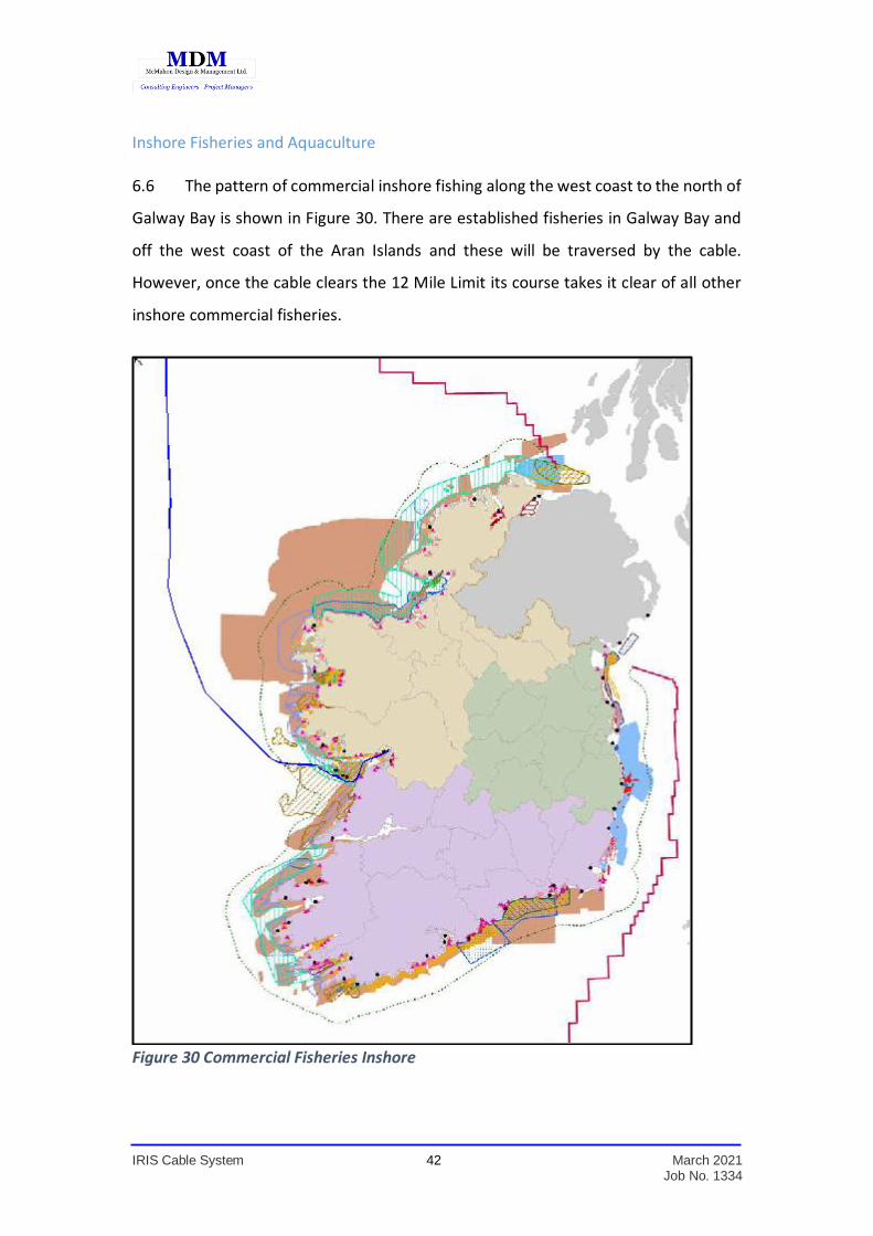
Inshore Fisheries and Aquaculture 6.6 The pattern of commercial inshore fishing along the west coast to the north of
Galway Bay is shown in Figure 30. There are established fisheries in Galway Bay and
off the west coast of the Aran Islands and these will be traversed by the cable.
However, once the cable clears the 12 Mile Limit its course takes it clear of all other
inshore commercial fisheries.
Figure 30 Commercial Fisheries Inshore
IRIS Cable System 43 March 2021 Job No. 1334
6.7 Liaison has been established with Fishermen’s Organisations in Galway Bay
and the Aran Islands and this will continue for Main-Lay operations as to ensure that
any potential impacts on commercial fishing interests will be minimised and that those
interests will have adequate notice of the cable installation operations.
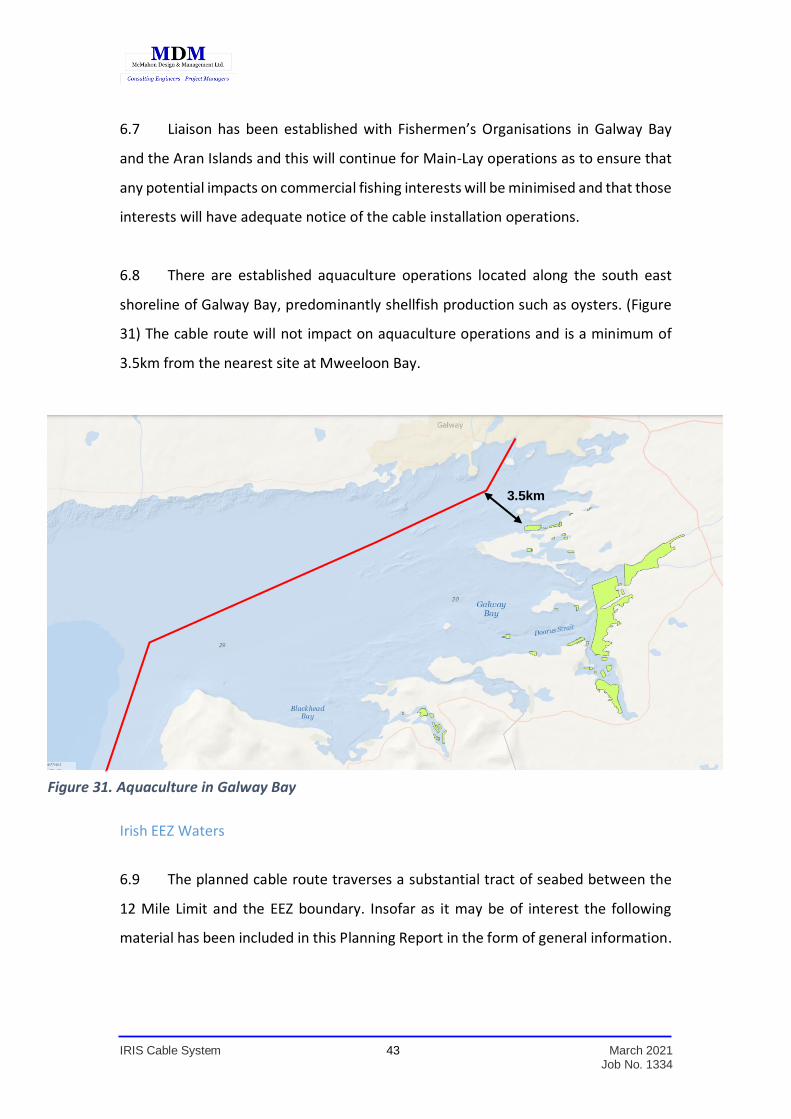
6.8 There are established aquaculture operations located along the south east
shoreline of Galway Bay, predominantly shellfish production such as oysters. (Figure
31) The cable route will not impact on aquaculture operations and is a minimum of
3.5km from the nearest site at Mweeloon Bay.
Irish EEZ Waters
6.9 The planned cable route traverses a substantial tract of seabed between the
12 Mile Limit and the EEZ boundary. Insofar as it may be of interest the following
material has been included in this Planning Report in the form of general information.
3.5km
Figure 31. Aquaculture in Galway Bay
IRIS Cable System 44 March 2021 Job No. 1334
Subsea Pipelines and Cables 6.10 The planned cable route lies over 60 kilometres west of the Corrib Gas
Field and will have no impact on the Offshore Installation facilities or on the pipeline
to shore.
6.11 The planned cable will cross a number of trans-Atlantic telecoms cables off the
Continental Shelf in Irish EEZ waters. The cables which will be crossed are AEC 1, the
Havfrue Spur, Hibernia-Segment A, Havfrue trans-Atlantic and the TAT-14 cable.
6.12 These cable crossings will all be in the deep waters of the Rockall Trough with
depths ranging from 2,800 m to 3,000 m. The precise locations of the individual
crossings may change locally to ensure that the IRIS cable will have adequate
separation from “Repeaters” on the respective existing cables.
Hydrocarbon Licence Blocks
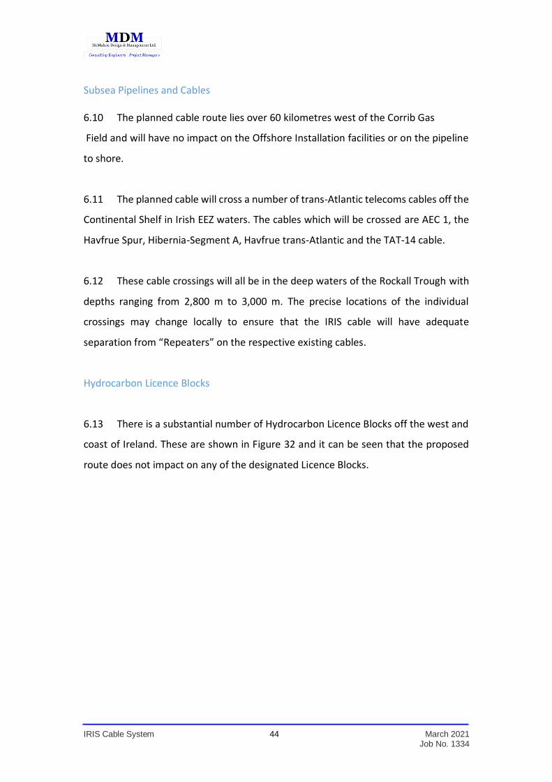
6.13 There is a substantial number of Hydrocarbon Licence Blocks off the west and
coast of Ireland. These are shown in Figure 32 and it can be seen that the proposed
route does not impact on any of the designated Licence Blocks.
IRIS Cable System 45 March 2021 Job No. 1334
Figure 32 Licence Blocks off the west and northwest of Ireland
Fishing in Irish EEZ Waters
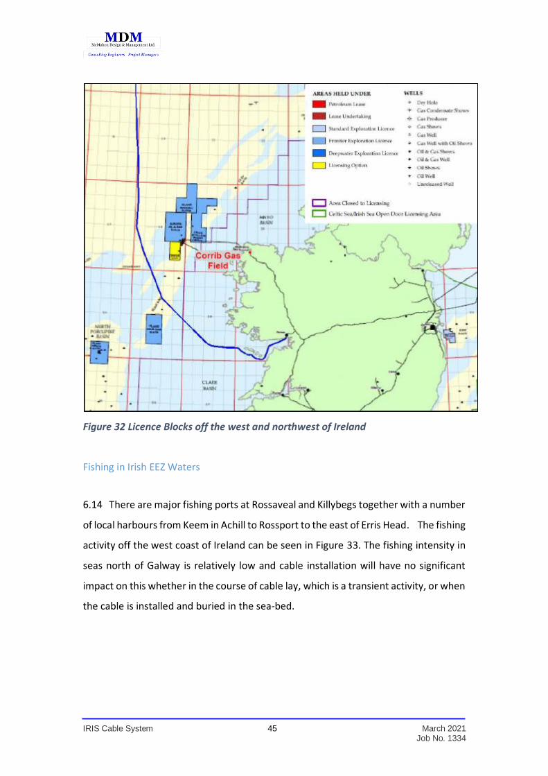
6.14 There are major fishing ports at Rossaveal and Killybegs together with a number
of local harbours from Keem in Achill to Rossport to the east of Erris Head. The fishing
activity off the west coast of Ireland can be seen in Figure 33. The fishing intensity in
seas north of Galway is relatively low and cable installation will have no significant
impact on this whether in the course of cable lay, which is a transient activity, or when
the cable is installed and buried in the sea-bed.
IRIS Cable System 46 March 2021 Job No. 1334
Figure 33. Commercial Fisheries Offshore.
Shipping
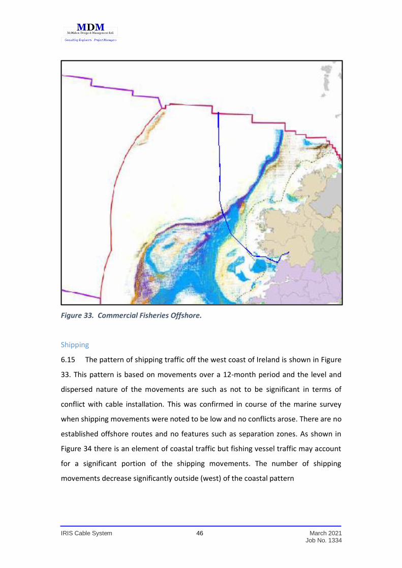
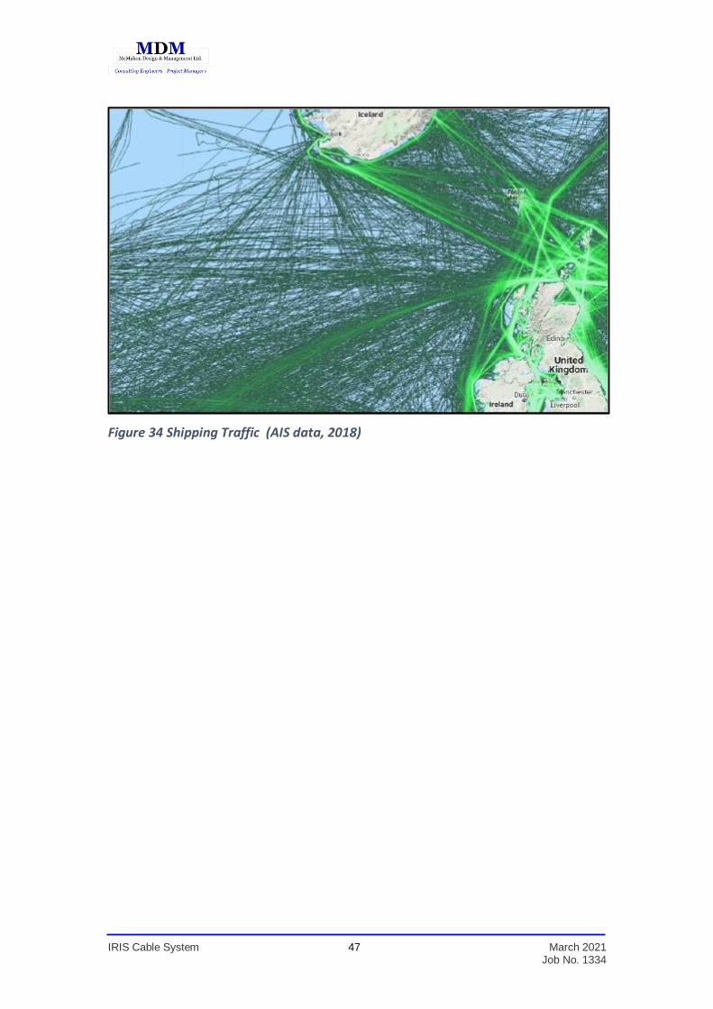
6.15 The pattern of shipping traffic off the west coast of Ireland is shown in Figure
33. This pattern is based on movements over a 12-month period and the level and
dispersed nature of the movements are such as not to be significant in terms of
conflict with cable installation. This was confirmed in course of the marine survey
when shipping movements were noted to be low and no conflicts arose. There are no
established offshore routes and no features such as separation zones. As shown in
Figure 34 there is an element of coastal traffic but fishing vessel traffic may account
for a significant portion of the shipping movements. The number of shipping
movements decrease significantly outside (west) of the coastal pattern
IRIS Cable System 47 March 2021 Job No. 1334
Figure 34 Shipping Traffic (AIS data, 2018)
IRIS Cable System 48 March 2021 Job No. 1334
7.0 NAVIGATIONAL SAFETY CONSIDERATIONS
7.1 The installation of the cable in Galway Bay and through the South Sound will
be co-ordinated with the Harbour Master at Galway Port. The cable installation is a
transient activity and a continuous operation. The Main-Lay Vessel will move at a rate
of 0.5 to 1 Knot. Compliance with the requirements of the International Regulations
for Preventing Collisions at Sea will be followed at all times and it is expected that
there will be no impact on shipping movements in and out of Galway Port.
7.2 The route of the cable through the South Sound ensures that it does not cross
the ferry routes operating out of Rossaveal. In the case of the ferries operating out of
Doolin it is planned to have direct liaison between the Main-Lay Vessel and the Ferry
Companies while the Main-Lay Vessel is traversing the South Sound.
7.3 The intensity of shipping traffic along the West and North West coast is quite
low and the pattern of shipping movements is quite diverse. There are no
requirements for any special measures.
Mitigation of Navigation Risk
7.4 Key points relating to mitigation of Navigational Risk associated with the
installation of the IRIS subsea cable system inside the 12-mile limit are as follows:
Subsea cable installation will be performed by a single, purpose-built lay vessel
and will comply fully with all requirements of the International Regulations for
Preventing Collisions at Sea.
The vessel will lay cable on a 24 hour per day basis and a full operational crew
will be on duty at all times.
The plan is that the cable will be laid and plough-buried in a single operation.
Vessel speed during cable laying will be of the order of 0.5 to 1 knot.
IRIS Cable System 49 March 2021 Job No. 1334
Prior to commencement of cable installation, the Dept. of the Environment
Community and Local Government will be notified of the planned start and the
estimated completion dates for the operation.
The Harbour Master at Galway Port will be informed of the Plan of Work and
of the planned start and estimated completion dates for the operation.
The Coastguard will be notified of the Plan of Work and of the planned start
and estimated completion dates for the operation.
Representatives of the local fishing fleets will be contacted and made aware of
planned operations. Arrangements will be put in place to provide next-day
position forecast throughout the cable-installation period.
Arrangements will be made for the publication of a formal Marine Notice
through the Department of Transport, Tourism and Sport and the notice will
provide vessel and contact details together with a general description of
operations and approximate dates of commencement and completion.
A local marine notice giving vessel details together with a general description
of operations and approximate dates of commencement and completion will
be published.
IRIS Cable System 50 March 2021 Job No. 1334
8.0 MARINE ARCHAEOLOGY
8.1 There is a significant library of data available from various surveys in the
selected route corridor. These include the Shipwreck Inventory of Ireland, the Irish
National Seabed Survey (INSS) and the Infomar Survey. These are supplemented with
knowledge gained from the marine cable route surveys.
8.2 The data available from this material has formed the basis for a Marine
Archaeology Report which has been prepared by Geomara Ltd. A copy of the report
is presented in Appendix 3.
8.3 The non-Technical Summary of the Marine Archaeology Report is as follows;
“Geomara have previously completed a Marine Archaeological Assessment of the Marine Survey and Site Investigation works. Following analysis of the survey and site investigations along with regard to the archaeological assessment and Environmental assessments a final Route Position List has been developed. This final route is the subject of this report This assessment comprises an introduction to the study area; and the identification of cultural heritage sites, features and deposits located along the proposed cable route corridor. In order to provide a comprehensive assessment, an extensive desk-based study of the route corridor has been undertaken. The desk based study has been followed up by an extensive review of the geophysical and geotechnical data. The results of the archaeological screening of the proposed geotechnical locations along the route corridor also form part of the assessment. All of the geotechnical CPT and sampling logs and the subsequent reports have been reviewed and nothing of an archaeological nature was noted in any of the cores or samples analysed. Following a full review of all the bathymetric and geophysical data the bathymetric geophysical charts of the survey corridor were cross referenced with the magnetometer and sonar target data. Nothing of an archaeological nature was noted. All of the magnetometer and sonar contacts have been avoided by the preferred route. The known shipwreck sites in Galway Bay and the recorded cultural heritage sites on the coast at Galway Bay, the Islands and along the coast of Clarehighlight the intense human activity in the general area from earliest times up to the present day (Appendix 3 and 4). This activity has the potential to yield associated features finds or deposits and these may be disturbed during the cable system installations. As outlined in this report, the Galway City Storm Damage Survey (see table 5) identified ship timbers and an old quay which are present on Ballyloughane beach.

IRIS Cable System 51 March 2021 Job No. 1334
The following mitigation recommendations are presented in connection with the proposed cable installation:
The location of all of the proposed trial pits and probing on the beach and on the foreshore should avoid the seven sites and find spots noted during the storm damage mitigation report and detailed in this report.
All of the proposed trial pit excavations and probing on the beach and on the foreshore should be subject to full archaeological monitoring.
The Horizontal Directional Drilling, beach manhole excavations and the exit trench excavations on the beach should be monitored by a suitably qualified archaeologist.
The cable installation on the beach at Ballyloughane from the HDD exit out to the low water line should be subject to licenced archaeological monitoring. Note should be taken of the location of the metal detector targets close to the RPL and any related features avoided by the trenching activities.
Archaeological monitoring of the pre-lay grapnel run should be undertaken in order to identify any previously unrecorded features, finds or deposits.
All trenching / ploughing should be the subject of licenced archaeological monitoring.
It is recommended that procedures should be put in place to ensure that any previously unrecorded cultural heritage assets encountered during the project should be assessed by a suitably qualified archaeologist and avoided by any future works
Should the proposed preferred route be subject to further revision, details of these revisions should be forwarded to the project archaeologist for assessment
It is recommended that procedures should be put in place to ensure that any previously unrecorded cultural heritage assets encountered during the project should be assessed by a suitably qualified archaeologist and avoided by the cable laying operations.
On completion of the cable installation a report will be produced summarising all archaeological aspects of the project and submitted to DCHG and the National Museum of Ireland”
IRIS Cable System 52 March 2021 Job No. 1334
9.0 NATURA IMPACT STATEMENT
9.1 A Natura Impact Statement was prepared for the construction works and cable
installation activities. The assessment was carried out by Altemar Ltd and a copy of
the Statement is presented in full in Appendix 4.
9.2 The conclusion of the Natura Impact Statement is as follows;
“In conclusion, no significant impacts are likely on the features of interest or the site specific conservation objectives of Natura 2000 sites as a result of the installation or operation of the cable, individually or in combination with other plans or projects. However, mitigation measures and construction phase controls are required and will be carried out in consultation with an ecologist and marine biologist. The proposed project will not adversely affect the integrity of Natura 2000 site.” “The proposed project will not adversely affect the integrity of the European site.”
IRIS Cable System 53 March 2021 Job No. 1334
10.0 ECOLOGICAL IMPACT ASSESSMENT
10.1 An Ecological Impact Assessment was also carried out for the construction
works and cable installation activities. The assessment was prepared by Altemar Ltd
and a copy of the Assessment Report is presented in full in Appendix 5.
10.2 The conclusion of the assessment are as follows;
“Residual impacts are impacts that remain once mitigation has been implemented, or impacts that cannot be mitigated against. As previously outlined from the early stage of this project use of Best Available Techniques (BAT) have been used in the planning and implementation of the project as they “represent a key measure for avoiding environmental impacts” (OSPAR, 2012). This has included optimal site selection, methodologies of cable laying and phasing of the project outside key ecological times such as the over-wintering bird season in order to reduce the ecological impact of the project on, not only the designated sites at the landfall location, but also the additional habitats out to, and beyond the 12nm limit out to the Irish EEZ. The use of BAT will also help to ensure the longevity and stability of this important piece of infrastructure. Cable laying will be outside over-wintering bird season and will not be close to tern nesting sites, for which this site is designated as an SPA. Works will be carried out during harbour seal breeding season. The nearest breeding site is 1.2km from the cable survey route and an MMO will be present for all surveys and the cable laying. Works are not proposed in the majority of the sensitive habitats listed as features of interest of the Galway Bay Complex SAC. However, the cable does pass through mudflat/sandflat in the intertidal and the impacts in these areas are deemed to be minor adverse short-term. In the subtidal areas classed as Large Shallow Inlets and Bays, considerable lengths have been taken to avoid undocumented sensitive communities that were encountered during video surveys for the project, specifically carried out to assess habitats in the subtidal within the SAC. Impacts to these habitats are deemed at worst to be minor adverse short-term. However, despite the use of BAT in addition to the outlined mitigation measures, residual impacts will remain. The laying, operation and subsequent decommissioning of the cable, if required, will have no significant impact on the integrity of a conservation site or its site specific conservation objectives. Impacts are primarily related to short-term minor adverse impacts due to disturbance over the period of the HDD, 1 day cable burial on the beach and the ploughing by the vessel in the shallow subtidal (1-2 days in the SAC). Mitigation measures have been proposed to minimise/eliminate negative impacts on species or habitats of conservation importance.”
“No significant environmental impacts are likely in relation to the construction or operation
of the proposed development.”

IRIS Cable System 54 March 2021 Job No. 1334
Appendix 1 – Drawings.
FORESHORE LICENCE MAPS:
1334-A-201 Foreshore Map 1
1334-A-202 Foreshore Map 2 – Inshore
1334-A-203 Foreshore Map 3 - Offshore
1334-A-204 Overall Route Map
1334-A-205 Horizontal Directional Drill
IRIS Cable System 55 March 2021 Job No. 1334
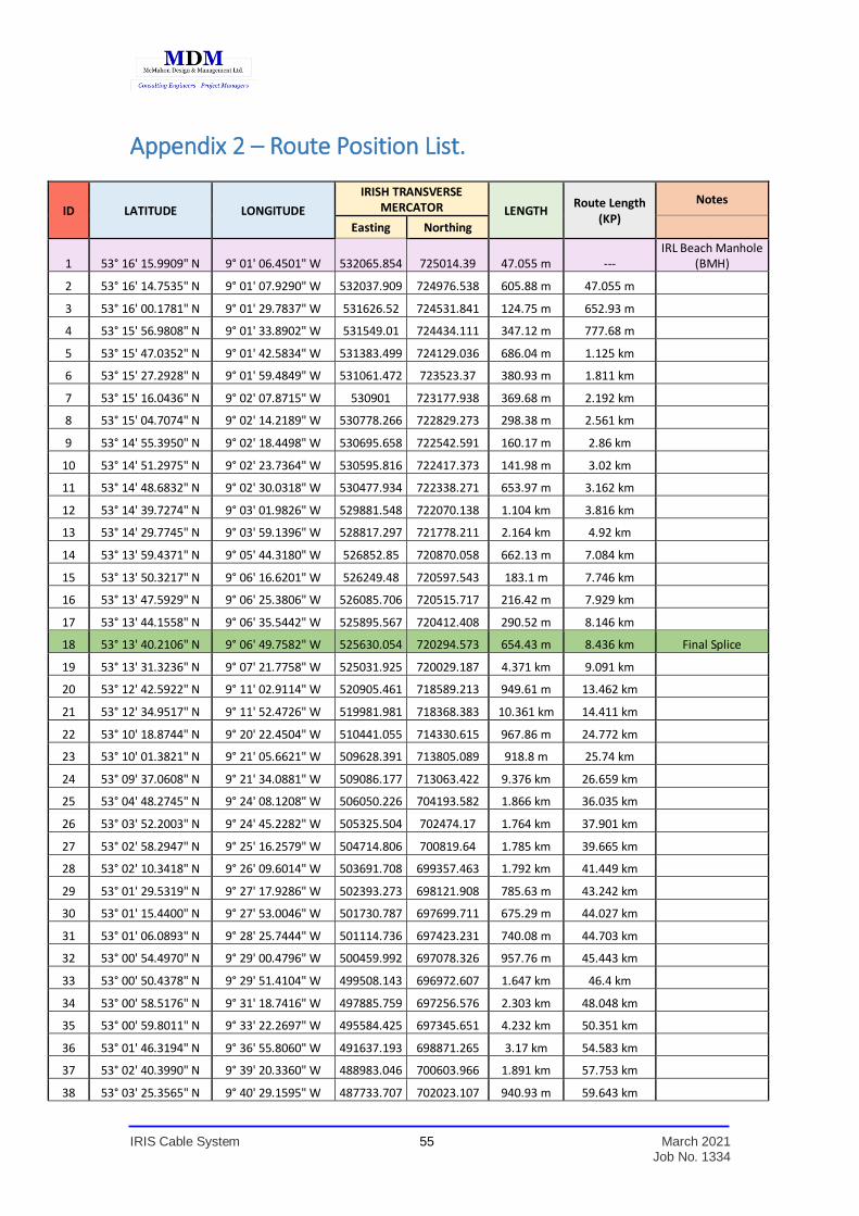
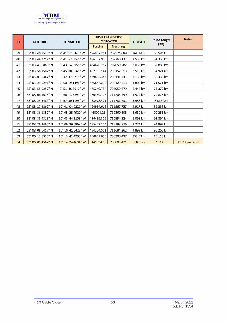
Appendix 2 – Route Position List.
ID LATITUDE LONGITUDE
IRISH TRANSVERSE MERCATOR LENGTH
Route Length (KP)
Notes
Easting Northing
1 53° 16' 15.9909" N 9° 01' 06.4501" W 532065.854 725014.39 47.055 m --- IRL Beach Manhole
(BMH)
2 53° 16' 14.7535" N 9° 01' 07.9290" W 532037.909 724976.538 605.88 m 47.055 m
3 53° 16' 00.1781" N 9° 01' 29.7837" W 531626.52 724531.841 124.75 m 652.93 m
4 53° 15' 56.9808" N 9° 01' 33.8902" W 531549.01 724434.111 347.12 m 777.68 m
5 53° 15' 47.0352" N 9° 01' 42.5834" W 531383.499 724129.036 686.04 m 1.125 km
6 53° 15' 27.2928" N 9° 01' 59.4849" W 531061.472 723523.37 380.93 m 1.811 km
7 53° 15' 16.0436" N 9° 02' 07.8715" W 530901 723177.938 369.68 m 2.192 km
8 53° 15' 04.7074" N 9° 02' 14.2189" W 530778.266 722829.273 298.38 m 2.561 km
9 53° 14' 55.3950" N 9° 02' 18.4498" W 530695.658 722542.591 160.17 m 2.86 km
10 53° 14' 51.2975" N 9° 02' 23.7364" W 530595.816 722417.373 141.98 m 3.02 km
11 53° 14' 48.6832" N 9° 02' 30.0318" W 530477.934 722338.271 653.97 m 3.162 km
12 53° 14' 39.7274" N 9° 03' 01.9826" W 529881.548 722070.138 1.104 km 3.816 km
13 53° 14' 29.7745" N 9° 03' 59.1396" W 528817.297 721778.211 2.164 km 4.92 km
14 53° 13' 59.4371" N 9° 05' 44.3180" W 526852.85 720870.058 662.13 m 7.084 km
15 53° 13' 50.3217" N 9° 06' 16.6201" W 526249.48 720597.543 183.1 m 7.746 km
16 53° 13' 47.5929" N 9° 06' 25.3806" W 526085.706 720515.717 216.42 m 7.929 km
17 53° 13' 44.1558" N 9° 06' 35.5442" W 525895.567 720412.408 290.52 m 8.146 km
18 53° 13' 40.2106" N 9° 06' 49.7582" W 525630.054 720294.573 654.43 m 8.436 km Final Splice
19 53° 13' 31.3236" N 9° 07' 21.7758" W 525031.925 720029.187 4.371 km 9.091 km
20 53° 12' 42.5922" N 9° 11' 02.9114" W 520905.461 718589.213 949.61 m 13.462 km
21 53° 12' 34.9517" N 9° 11' 52.4726" W 519981.981 718368.383 10.361 km 14.411 km
22 53° 10' 18.8744" N 9° 20' 22.4504" W 510441.055 714330.615 967.86 m 24.772 km
23 53° 10' 01.3821" N 9° 21' 05.6621" W 509628.391 713805.089 918.8 m 25.74 km
24 53° 09' 37.0608" N 9° 21' 34.0881" W 509086.177 713063.422 9.376 km 26.659 km
25 53° 04' 48.2745" N 9° 24' 08.1208" W 506050.226 704193.582 1.866 km 36.035 km
26 53° 03' 52.2003" N 9° 24' 45.2282" W 505325.504 702474.17 1.764 km 37.901 km
27 53° 02' 58.2947" N 9° 25' 16.2579" W 504714.806 700819.64 1.785 km 39.665 km
28 53° 02' 10.3418" N 9° 26' 09.6014" W 503691.708 699357.463 1.792 km 41.449 km
29 53° 01' 29.5319" N 9° 27' 17.9286" W 502393.273 698121.908 785.63 m 43.242 km
30 53° 01' 15.4400" N 9° 27' 53.0046" W 501730.787 697699.711 675.29 m 44.027 km
31 53° 01' 06.0893" N 9° 28' 25.7444" W 501114.736 697423.231 740.08 m 44.703 km
32 53° 00' 54.4970" N 9° 29' 00.4796" W 500459.992 697078.326 957.76 m 45.443 km
33 53° 00' 50.4378" N 9° 29' 51.4104" W 499508.143 696972.607 1.647 km 46.4 km
34 53° 00' 58.5176" N 9° 31' 18.7416" W 497885.759 697256.576 2.303 km 48.048 km
35 53° 00' 59.8011" N 9° 33' 22.2697" W 495584.425 697345.651 4.232 km 50.351 km
36 53° 01' 46.3194" N 9° 36' 55.8060" W 491637.193 698871.265 3.17 km 54.583 km
37 53° 02' 40.3990" N 9° 39' 20.3360" W 488983.046 700603.966 1.891 km 57.753 km
38 53° 03' 25.3565" N 9° 40' 29.1595" W 487733.707 702023.107 940.93 m 59.643 km
IRIS Cable System 56 March 2021 Job No. 1334
ID LATITUDE LONGITUDE
IRISH TRANSVERSE MERCATOR LENGTH
Route Length (KP)
Notes
Easting Northing
39 53° 03' 40.9545" N 9° 41' 12.5447" W 486937.261 702524.089 768.44 m 60.584 km
40 53° 03' 48.2252" N 9° 41' 52.0046" W 486207.953 702766.131 1.535 km 61.353 km
41 53° 03' 43.5883" N 9° 43' 14.0955" W 484676.287 702659.282 2.033 km 62.888 km
42 53° 03' 58.1507" N 9° 45' 00.5660" W 482705.144 703157.313 3.518 km 64.921 km
43 53° 05' 01.6367" N 9° 47' 37.3715" W 479835.344 705191.431 3.132 km 68.439 km
44 53° 05' 29.5291" N 9° 50' 19.1498" W 476847.235 706129.713 1.808 km 71.571 km
45 53° 05' 55.0257" N 9° 51' 46.6040" W 475240.754 706959.679 6.447 km 73.379 km
46 53° 08' 08.1676" N 9° 56' 13.3899" W 470389.705 711205.799 1.524 km 79.826 km
47 53° 08' 25.5489" N 9° 57' 30.1198" W 468978.421 711781.731 3.988 km 81.35 km
48 53° 08' 27.9862" N 10° 01' 04.6226" W 464994.613 711967.757 4.917 km 85.338 km
49 53° 08' 36.1359" N 10° 05' 28.7920" W 460093.26 712360.505 3.639 km 90.255 km
50 53° 08' 38.9313" N 10° 08' 44.5103" W 456459.309 712554.524 1.098 km 93.894 km
51 53° 08' 26.2460" N 10° 09' 39.6969" W 455422.104 712193.376 1.274 km 94.992 km
52 53° 08' 08.6417" N 10° 10' 41.6428" W 454254.501 711684.262 4.899 km 96.266 km
53 53° 06' 12.8325" N 10° 13' 41.4295" W 450802.056 708208.437 832.59 m 101.16 km
54 53° 06' 05.4562" N 10° 14' 24.4694" W 449994.5 708005.471 5.83 km 102 km IRL 12nm Limit

IRIS Cable System 57 March 2021 Job No. 1334
Appendix 3 – Marine Archaeology Assessment Report.

IRIS Cable System 58 March 2021 Job No. 1334
Appendix 4– AA Screening and Natura Impact Statement.

IRIS Cable System 59 March 2021 Job No. 1334
Appendix 5 – Ecological Impact Assessment Report.


![Ropes for Subsea Cable Laying - brunton-shaw.com · [ BUOY & GRAPNEL ] Cable Laid combined (wire and natural fibre) ropes specially designed for Subsea Cable Laying duties Ropes for](https://img.pdfslide.us/doc/110x75/5e126c3ed43a5b3e643fb493/ropes-for-subsea-cable-laying-brunton-shawcom-buoy-grapnel-cable-laid.jpg)