Embed Size (px)
Citation preview
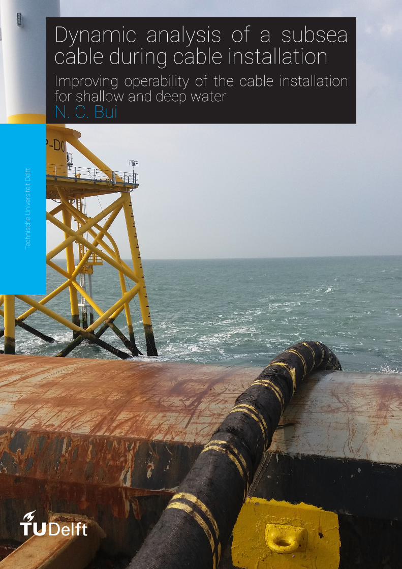
Dynamic analysis of a subseacable during cable installationImproving operability of the cable installationfor shallow and deep waterN. C. Bui
Tech
nisc
heUn
iversite
itDe
lft

Dynamic analysis of asubsea cable duringcable installation
Improving operability of the cable installationfor shallow and deep water
by
N. C. Buito obtain the degree of Master of Science
at the Delft University of Technology,to be defended publicly on Tuesday November 7, 2016 at 13:00 AM.
Student number: 4050436Project duration: November 23, 2015 – November 7, 2016Thesis committee: Prof. dr. A. Metrikine, TU Delft, Chairman
Ir. J. De Oliveira Barbosa, TU DelftIr. A. Jarquin Laguna, TU DelftDr. Ir. K.N. van Dalen, TU DelftIr. G. Natarajan , Tideway Offshore SolutionsIr. C. Visser , Tideway Offshore SolutionsIr. M. Hassan , Tideway Offshore Solutions
This thesis is confidential and cannot be made public until November 7, 2021.
An electronic version of this thesis is available at http://repository.tudelft.nl/.

Abstract
DELFT UNIVERSITY OF TECHNOLOGYTIDEWAY OFFSHORE SOLUTIONS
Master of Science Offshore and Dredging EngineeringDynamic Analysis of a subsea cable during cable installation
by N. C. Bui
The investigation into the dynamic behavior of a cable during installation was done with the aim of improvingcable installation for safety, operational and commercial value. In order to increase the operational limit ofthe vessel during cable installation, the investigation into improvement systems was desired. The workabilityof a vessel during cable laying operations is governed by the cable integrity design criteria such as maximumtension, touch-down-point tension, side-wall-pressure and the minimum bending radius. In practice dur-ing cable-laying the touch-down-point tension and minimum bend radius cannot be measured. Thereforea dynamic analysis of the subsea cable is required to determine the cable motions and tension fluctuations.The main objective of this Master Thesis is to develop and investigate two cable lay improvement systems.Both systems are modeled in OrcaFlex software to analyze its improved effect on the workability during cablelaying operations.
The cable integrity design conditions are compensated by either active force control at the tensioner systemsor by active position control near the departure point on the chute. By controlling one of the two parame-ters the catenary shape is stabilized and therefore the fluctuating tension and cable motions are controlled.Force control is developed in OrcaFlex by a Tensioner System controlling the tensions in the load cells at atarget value, position control is controlling the chute-end location with an Active Heave Compensated ChuteSystem. To actively control the improvement systems, a Proportional-Integral-Derivative (PID)-Controller isused in OrcaFlex as external function where the performance dependents on the defined PID-Parameters.
To optimize the improvement systems further, first simplified 1-Degree Of Freedom (DOF) analytical positioncontrolled models are developed to identify the initial guess PID-Parameters. Subsequently, a 6-DOF posi-tion (left picture) and force (right picture) controlled models in OrcaFlex, was developed and simulated usingthe obtained initial guess PID-Parameters. In OrcaFlex the PID-Parameters are further adjusted using regularwave theory to achieve the full performance capacity of the improvement systems based on data obtainedfrom existing systems on the market. Finally a detailed numerical model is developed and analyzed for irreg-ular wave heights to obtain the workability plots. The numerical models are subjected to environmental andhydrodynamic loads during a three-hour simulation.
Results show that the force and position controlled systems are able to improve the cable integrity designconditions significantly, but more for the position controlled system. The force controlled system is limitedby the pay-out velocity for deep water and by cable compression and the minimum bending radius at shallowwater, whereas the position controlled system is limited by the stroke of the cylinder. Also it has been foundthat the controller performance for the force controlled system must be adjusted for different range of wa-terdepth, while the position controlled system maintains the same performance. Furthermore, the positioncontrolled system is able to hold the catenary shape nearly still, significantly more that it does for the tensioncontrolled system. In conclusion an increased workability during cable installation can be achieved with oneof the improvement systems.
iii

Preface
First of all, I would like to thank my graduation committee for their excellent help, input, discussions andcomments on the work done; Andrei Metrikine, Joao barbosa, Antonio Laguna, Connie Visser, GowthamNatarajan and Mohamed Hassan. Also the support of a friend Luuc Duijm is highly appropriated for hisknowledge on OrcaFlex and control system.
secondly, I am grateful to my girlfriend (Dewi Wesselman), family, friends and housemates for their supportand understanding. Special thanks to Erik Heeres for borrowing his Laptop when mine broke down after 4months research. Also the information received for the tensioner system and hydraulic cylinder was madepossible by IHC SAS bv and Bosch Group Rexroth.
Finally, many thanks to Tideway Offshore Solutions for the opportunity to graduate at their company on avery interesting topic and the provided data to develop an innovative solution to improve the workability of avessel during cable installation. Without all that, this report would not have been made possible.
N. C. BuiDelft, October 2016
v

Contents
Abstract iii
Preface v
Contents x
List of Figures xi
List of Tables xiii
List of Acronyms xv
List of Symbols xv
1 Introduction 11.1 Tideway Offshore Solutions . . . . . . . . . . . . . . . . . . . . . . . . . . . . . . . . . . . . 21.2 Problem Description . . . . . . . . . . . . . . . . . . . . . . . . . . . . . . . . . . . . . . . 21.3 Problem Statement . . . . . . . . . . . . . . . . . . . . . . . . . . . . . . . . . . . . . . . . 31.4 Research Objectives. . . . . . . . . . . . . . . . . . . . . . . . . . . . . . . . . . . . . . . . 3
1.4.1 Sub-Objectives. . . . . . . . . . . . . . . . . . . . . . . . . . . . . . . . . . . . . . . 31.5 Approach of the project . . . . . . . . . . . . . . . . . . . . . . . . . . . . . . . . . . . . . . 4
2 Offshore cable installation 52.1 Living Stone vessel . . . . . . . . . . . . . . . . . . . . . . . . . . . . . . . . . . . . . . . . 52.2 Cable Lay Methods . . . . . . . . . . . . . . . . . . . . . . . . . . . . . . . . . . . . . . . . 6
2.2.1 Cable-Lay installation Stages. . . . . . . . . . . . . . . . . . . . . . . . . . . . . . . . 62.2.2 Subsea power cable projects . . . . . . . . . . . . . . . . . . . . . . . . . . . . . . . . 62.2.3 Subsea power cable properties . . . . . . . . . . . . . . . . . . . . . . . . . . . . . . . 82.2.4 Horizontal and vertical tensioner cable lay. . . . . . . . . . . . . . . . . . . . . . . . . 8
2.3 Cable installation equipment . . . . . . . . . . . . . . . . . . . . . . . . . . . . . . . . . . . 92.3.1 Cable storage . . . . . . . . . . . . . . . . . . . . . . . . . . . . . . . . . . . . . . . 92.3.2 Cable highway . . . . . . . . . . . . . . . . . . . . . . . . . . . . . . . . . . . . . . . 102.3.3 Cable tensioner systems . . . . . . . . . . . . . . . . . . . . . . . . . . . . . . . . . . 112.3.4 Chute . . . . . . . . . . . . . . . . . . . . . . . . . . . . . . . . . . . . . . . . . . . 132.3.5 Possible improvement systems. . . . . . . . . . . . . . . . . . . . . . . . . . . . . . . 13
3 General Cable Laymechanics 153.1 Cable Lay Definitions . . . . . . . . . . . . . . . . . . . . . . . . . . . . . . . . . . . . . . . 153.2 Cable Installation Loads . . . . . . . . . . . . . . . . . . . . . . . . . . . . . . . . . . . . . 15
3.2.1 Static Calculations . . . . . . . . . . . . . . . . . . . . . . . . . . . . . . . . . . . . . 153.2.2 Dynamic Calculations . . . . . . . . . . . . . . . . . . . . . . . . . . . . . . . . . . . 15
3.3 Cable Integrity Design conditions. . . . . . . . . . . . . . . . . . . . . . . . . . . . . . . . . 153.4 Cable motions . . . . . . . . . . . . . . . . . . . . . . . . . . . . . . . . . . . . . . . . . . 15
3.4.1 Tension fluctuations: Analytically explained . . . . . . . . . . . . . . . . . . . . . . . . 153.4.2 Tension fluctuations: Numerically simulated . . . . . . . . . . . . . . . . . . . . . . . 15
3.5 Concept improvement system . . . . . . . . . . . . . . . . . . . . . . . . . . . . . . . . . . 153.5.1 Improved system 1: CT Tensioner System . . . . . . . . . . . . . . . . . . . . . . . . . 153.5.2 Improved system 2: HCC System. . . . . . . . . . . . . . . . . . . . . . . . . . . . . . 15
3.6 Environmental Loads . . . . . . . . . . . . . . . . . . . . . . . . . . . . . . . . . . . . . . . 153.6.1 Fluid Particle Velocity from waves for analysis . . . . . . . . . . . . . . . . . . . . . . . 153.6.2 Wave spectra for analysis. . . . . . . . . . . . . . . . . . . . . . . . . . . . . . . . . . 15
vii
viii Contents
3.7 Hydrodynamic Loads . . . . . . . . . . . . . . . . . . . . . . . . . . . . . . . . . . . . . . . 153.7.1 Drag Force . . . . . . . . . . . . . . . . . . . . . . . . . . . . . . . . . . . . . . . . . 153.7.2 Inertia Force . . . . . . . . . . . . . . . . . . . . . . . . . . . . . . . . . . . . . . . . 15
3.8 Operational loads . . . . . . . . . . . . . . . . . . . . . . . . . . . . . . . . . . . . . . . . . 153.8.1 Vessel Response equations . . . . . . . . . . . . . . . . . . . . . . . . . . . . . . . . . 153.8.2 Chute Heave response . . . . . . . . . . . . . . . . . . . . . . . . . . . . . . . . . . . 153.8.3 Chute maximum heave response . . . . . . . . . . . . . . . . . . . . . . . . . . . . . 15
3.9 Chapter summary. . . . . . . . . . . . . . . . . . . . . . . . . . . . . . . . . . . . . . . . . 15
4 Analytical Analysis of Improvement Systems 174.1 Control Theory . . . . . . . . . . . . . . . . . . . . . . . . . . . . . . . . . . . . . . . . . . 17
4.1.1 Open-Loop-System . . . . . . . . . . . . . . . . . . . . . . . . . . . . . . . . . . . . 174.1.2 Closed-Loop-System . . . . . . . . . . . . . . . . . . . . . . . . . . . . . . . . . . . . 174.1.3 Transferfunction: General Theory . . . . . . . . . . . . . . . . . . . . . . . . . . . . . 174.1.4 PID-Controller Theory . . . . . . . . . . . . . . . . . . . . . . . . . . . . . . . . . . . 17
4.2 Analytical Model: CT Tensioner System . . . . . . . . . . . . . . . . . . . . . . . . . . . . . . 174.2.1 Tensioner System modeling . . . . . . . . . . . . . . . . . . . . . . . . . . . . . . . . 174.2.2 Vessel response influences . . . . . . . . . . . . . . . . . . . . . . . . . . . . . . . . . 174.2.3 Cable static force influences . . . . . . . . . . . . . . . . . . . . . . . . . . . . . . . . 174.2.4 Force actuator . . . . . . . . . . . . . . . . . . . . . . . . . . . . . . . . . . . . . . . 174.2.5 Equation of Motion: Tensioner system . . . . . . . . . . . . . . . . . . . . . . . . . . . 174.2.6 Transferfunction: CT Tensioner system . . . . . . . . . . . . . . . . . . . . . . . . . . 17
4.3 Analytical Model: Heave Compensated Chute System . . . . . . . . . . . . . . . . . . . . . . 174.3.1 Motion compensated Cylinder modeling . . . . . . . . . . . . . . . . . . . . . . . . . 174.3.2 Vessel response influences . . . . . . . . . . . . . . . . . . . . . . . . . . . . . . . . . 174.3.3 Cable static force influences . . . . . . . . . . . . . . . . . . . . . . . . . . . . . . . . 174.3.4 Force Actuator . . . . . . . . . . . . . . . . . . . . . . . . . . . . . . . . . . . . . . . 174.3.5 HCC System: Equation of Motion . . . . . . . . . . . . . . . . . . . . . . . . . . . . . 174.3.6 Transferfunction HCC System . . . . . . . . . . . . . . . . . . . . . . . . . . . . . . . 17
4.4 Chapter summary. . . . . . . . . . . . . . . . . . . . . . . . . . . . . . . . . . . . . . . . . 17
5 Numerical Analysis of Improvement systems 195.1 General OrcaFlex software description . . . . . . . . . . . . . . . . . . . . . . . . . . . . . . 195.2 OrcaFlex Objects and external influences modeling. . . . . . . . . . . . . . . . . . . . . . . . 19
5.2.1 Line Object. . . . . . . . . . . . . . . . . . . . . . . . . . . . . . . . . . . . . . . . . 195.2.2 Winch Object . . . . . . . . . . . . . . . . . . . . . . . . . . . . . . . . . . . . . . . 195.2.3 Shapes . . . . . . . . . . . . . . . . . . . . . . . . . . . . . . . . . . . . . . . . . . . 195.2.4 Vessel object; "Living Stone" . . . . . . . . . . . . . . . . . . . . . . . . . . . . . . . . 19
5.3 Simulation model: Static Analysis . . . . . . . . . . . . . . . . . . . . . . . . . . . . . . . . . 195.4 Simulation model: Dynamic Analysis . . . . . . . . . . . . . . . . . . . . . . . . . . . . . . . 19
5.4.1 Solution method . . . . . . . . . . . . . . . . . . . . . . . . . . . . . . . . . . . . . . 195.4.2 Explicit solver . . . . . . . . . . . . . . . . . . . . . . . . . . . . . . . . . . . . . . . 195.4.3 Implicit solver . . . . . . . . . . . . . . . . . . . . . . . . . . . . . . . . . . . . . . . 195.4.4 Stages . . . . . . . . . . . . . . . . . . . . . . . . . . . . . . . . . . . . . . . . . . . 19
5.5 OrcaFlex modeling: CT Model . . . . . . . . . . . . . . . . . . . . . . . . . . . . . . . . . . 195.5.1 Modeling of the flared chute . . . . . . . . . . . . . . . . . . . . . . . . . . . . . . . . 195.5.2 Modeling of the active force controlled tensioner system . . . . . . . . . . . . . . . . . 195.5.3 Final Mode: CT Model . . . . . . . . . . . . . . . . . . . . . . . . . . . . . . . . . . . 19
5.6 OrcaFlex modeling: AHCC Model . . . . . . . . . . . . . . . . . . . . . . . . . . . . . . . . . 195.6.1 Modeling of the Chute Structure . . . . . . . . . . . . . . . . . . . . . . . . . . . . . . 195.6.2 Modeling of the Frame Structure . . . . . . . . . . . . . . . . . . . . . . . . . . . . . . 195.6.3 Modeling an active positioned controlled cylinder . . . . . . . . . . . . . . . . . . . . . 195.6.4 Final model: AHCC Model . . . . . . . . . . . . . . . . . . . . . . . . . . . . . . . . . 19
5.7 Chapter summary. . . . . . . . . . . . . . . . . . . . . . . . . . . . . . . . . . . . . . . . . 19
N.C. Bui
Contents ix
6 Model Analysis: Tensioner System 216.1 Analytical analysis . . . . . . . . . . . . . . . . . . . . . . . . . . . . . . . . . . . . . . . . 21
6.1.1 System Response. . . . . . . . . . . . . . . . . . . . . . . . . . . . . . . . . . . . . . 216.1.2 Open-loop-system . . . . . . . . . . . . . . . . . . . . . . . . . . . . . . . . . . . . . 216.1.3 Closed-loop-system . . . . . . . . . . . . . . . . . . . . . . . . . . . . . . . . . . . . 216.1.4 Concluding remarks on analytical analysis: Tensioner system . . . . . . . . . . . . . . . 21
6.2 Numerical CT Model Analysis: OrcaFlex software . . . . . . . . . . . . . . . . . . . . . . . . . 216.2.1 Tuned PID-Parameter analysis . . . . . . . . . . . . . . . . . . . . . . . . . . . . . . . 216.2.2 Tensioner system performance analysis . . . . . . . . . . . . . . . . . . . . . . . . . . 216.2.3 Final Constant Tension System analysis . . . . . . . . . . . . . . . . . . . . . . . . . . 21
6.3 Chapter summary. . . . . . . . . . . . . . . . . . . . . . . . . . . . . . . . . . . . . . . . . 216.3.1 Analytical CT Model . . . . . . . . . . . . . . . . . . . . . . . . . . . . . . . . . . . . 216.3.2 Numerical CT Model . . . . . . . . . . . . . . . . . . . . . . . . . . . . . . . . . . . . 21
7 Model Analysis: Heave Compensated Chute System 237.1 Analytical analysis . . . . . . . . . . . . . . . . . . . . . . . . . . . . . . . . . . . . . . . . 23
7.1.1 System Response. . . . . . . . . . . . . . . . . . . . . . . . . . . . . . . . . . . . . . 237.1.2 Open-loop-system . . . . . . . . . . . . . . . . . . . . . . . . . . . . . . . . . . . . . 237.1.3 Closed-loop-system . . . . . . . . . . . . . . . . . . . . . . . . . . . . . . . . . . . . 237.1.4 Concluding remarks on analytical analysis: HCC system. . . . . . . . . . . . . . . . . . 23
7.2 Numerical HCC Model Analysis: OrcaFlex software . . . . . . . . . . . . . . . . . . . . . . . . 237.2.1 Tuned PID-Parameter analysis . . . . . . . . . . . . . . . . . . . . . . . . . . . . . . . 237.2.2 Final Heave Compensated Chute System analysis . . . . . . . . . . . . . . . . . . . . . 23
7.3 Chapter summary. . . . . . . . . . . . . . . . . . . . . . . . . . . . . . . . . . . . . . . . . 237.3.1 Analytical AHCC Model . . . . . . . . . . . . . . . . . . . . . . . . . . . . . . . . . . 237.3.2 Numerical AHCC Model . . . . . . . . . . . . . . . . . . . . . . . . . . . . . . . . . . 23
8 Workability Analysis CT Tensioner System and AHCC System 258.1 General Model: Workability Analysis . . . . . . . . . . . . . . . . . . . . . . . . . . . . . . . 258.2 Workability CT Model Analysis . . . . . . . . . . . . . . . . . . . . . . . . . . . . . . . . . . 25
8.2.1 CT Model: Top Tension of the cable . . . . . . . . . . . . . . . . . . . . . . . . . . . . 258.3 Workability HCC Model Analysis . . . . . . . . . . . . . . . . . . . . . . . . . . . . . . . . . 25
8.3.1 AHCC Model: Top Tension of the cable . . . . . . . . . . . . . . . . . . . . . . . . . . 258.4 Workability plots . . . . . . . . . . . . . . . . . . . . . . . . . . . . . . . . . . . . . . . . . 258.5 Chapter summary. . . . . . . . . . . . . . . . . . . . . . . . . . . . . . . . . . . . . . . . . 25
9 Conclusions 2710 Recommendations 29A Tideway Flinstone Vessel Visit: Cable Repair project 31B Project cases 33
B.1 Project: Johan Sverdrup . . . . . . . . . . . . . . . . . . . . . . . . . . . . . . . . . . . . . . 33B.2 Project: Thornton Bank . . . . . . . . . . . . . . . . . . . . . . . . . . . . . . . . . . . . . . 33
C Product information 35C.1 Hydraulic Cylinder . . . . . . . . . . . . . . . . . . . . . . . . . . . . . . . . . . . . . . . . 35
C.1.1 Hydraulic Cylinder Calculator . . . . . . . . . . . . . . . . . . . . . . . . . . . . . . . 35C.2 Tensioner System . . . . . . . . . . . . . . . . . . . . . . . . . . . . . . . . . . . . . . . . . 35C.3 Export Cable properties . . . . . . . . . . . . . . . . . . . . . . . . . . . . . . . . . . . . . . 35C.4 Flared chute structure. . . . . . . . . . . . . . . . . . . . . . . . . . . . . . . . . . . . . . . 35C.5 Heave compensated Chute Structure . . . . . . . . . . . . . . . . . . . . . . . . . . . . . . . 35
D Model Analysis Sensitivity study’s 37D.1 CT system Deadband . . . . . . . . . . . . . . . . . . . . . . . . . . . . . . . . . . . . . . . 37D.2 CT system Friction . . . . . . . . . . . . . . . . . . . . . . . . . . . . . . . . . . . . . . . . 37D.3 HCC system Friction . . . . . . . . . . . . . . . . . . . . . . . . . . . . . . . . . . . . . . . 37D.4 OrcaFlex Friction . . . . . . . . . . . . . . . . . . . . . . . . . . . . . . . . . . . . . . . . . 37D.5 OrcaFlex Contact normal Stiffness . . . . . . . . . . . . . . . . . . . . . . . . . . . . . . . . 37
N.C. Bui
D.6 OrcaFlex Contact shear Stiffness . . . . . . . . . . . . . . . . . . . . . . . . . . . . . . . . . 37D.6.1 OrcaFlex Line segmentation . . . . . . . . . . . . . . . . . . . . . . . . . . . . . . . . 37D.6.2 OrcaFlex model validation . . . . . . . . . . . . . . . . . . . . . . . . . . . . . . . . . 37
E Workability Analysis Results 39E.1 General Model . . . . . . . . . . . . . . . . . . . . . . . . . . . . . . . . . . . . . . . . . . 39E.2 CT Model . . . . . . . . . . . . . . . . . . . . . . . . . . . . . . . . . . . . . . . . . . . . . 39E.3 AHCC Model . . . . . . . . . . . . . . . . . . . . . . . . . . . . . . . . . . . . . . . . . . . 39
F Morphological Overview decisionmaking 41F.1 Procedure . . . . . . . . . . . . . . . . . . . . . . . . . . . . . . . . . . . . . . . . . . . . . 41F.2 Basic design criteria. . . . . . . . . . . . . . . . . . . . . . . . . . . . . . . . . . . . . . . . 41
F.2.1 Partial Functions & Various possibilities . . . . . . . . . . . . . . . . . . . . . . . . . . 41
G Chute port-side-center vessel 43H Transferfunction: Mitigation Solutions 45
H.1 Transferfunction: Tensioner System. . . . . . . . . . . . . . . . . . . . . . . . . . . . . . . . 45H.2 Transferfunction:Heave Compensated Chute System . . . . . . . . . . . . . . . . . . . . . . . 45
I External Function in Python: PID-Controller 47I.1 CT Tensioner System External Function. . . . . . . . . . . . . . . . . . . . . . . . . . . . . . 47I.2 HCC System External Function . . . . . . . . . . . . . . . . . . . . . . . . . . . . . . . . . . 47
Bibliography 49
List of Figures
1.1 A subsea cable cut in half for inspection . . . . . . . . . . . . . . . . . . . . . . . . . . . . . . . . . . 11.2 Example of a small computer network power cable damage due to high tensile loads, source:
https://www.dreamstime.com . . . . . . . . . . . . . . . . . . . . . . . . . . . . . . . . . . . . . . . 21.3 Approach of the MSc Thesis divided into three main steps; Analytical Model, Numerical model
and results . . . . . . . . . . . . . . . . . . . . . . . . . . . . . . . . . . . . . . . . . . . . . . . . . . . 4
2.1 Livingstone vessel profile . . . . . . . . . . . . . . . . . . . . . . . . . . . . . . . . . . . . . . . . . . 52.2 An infield cable connected between two offshore wind turbine structures. The cable is buried
beneath the seabed . . . . . . . . . . . . . . . . . . . . . . . . . . . . . . . . . . . . . . . . . . . . . . 72.3 An export cable connection between an offshore platform and an onshore structure. The cable
is buried beneath the seabed . . . . . . . . . . . . . . . . . . . . . . . . . . . . . . . . . . . . . . . . 72.4 An interconnection between an offshore platform and an onshore structure. The cable is buried
beneath the seabed . . . . . . . . . . . . . . . . . . . . . . . . . . . . . . . . . . . . . . . . . . . . . . 72.5 An interconnection between an offshore platform and an onshore structure. The cable is buried
beneath the seabed, [2] . . . . . . . . . . . . . . . . . . . . . . . . . . . . . . . . . . . . . . . . . . . 82.6 Left you see an illustration of a horizontal tensioner cable lay vessel, source: Germany: NSW
Charters Cable Laying Vessel MV Aura. Right illustration you see a semi-vertical tensioner cablelay vessel, source: Subsea 7 reel-lay vessel seven Oceans. . . . . . . . . . . . . . . . . . . . . . . . . 9
2.7 Top view of a Living Stone with an example of how the cable lay deck-layout could look like . . . 92.8 Different cable storage principles; (1) Turntable, (2) Carousel, (3) Cable Reel, and (4) Static Tank 102.9 (1) 10t baricon tracked tensioners, source: 4equipment, (2) Linear Belt Engine, source: Timber-
land equipment limited, (3) Linear wheel cable engine, source: Hulst Innovation cable equip-ment B.V. . . . . . . . . . . . . . . . . . . . . . . . . . . . . . . . . . . . . . . . . . . . . . . . . . . . . 11
2.10 Highlighted in color, Red: track-pads, Blue: Motor, Orange: Gearbox, ref: Tideway Drawings . . 122.11 These are pictures of existing Chute types, Flared Chute(1), Straight Chute fixed(2), Straight
Chute Rotating wheel(3), [11] . . . . . . . . . . . . . . . . . . . . . . . . . . . . . . . . . . . . . . . . 132.12 PID Setup Screen of a tensioner on Tension Control, [6]. . . . . . . . . . . . . . . . . . . . . . . . . 132.13 Left you see a realistic Heave Compensated Chute (HCC) build on a vessel and right you see an
artist impression of the HCC, [5] . . . . . . . . . . . . . . . . . . . . . . . . . . . . . . . . . . . . . . 142.14 Depressor, left figure shows a realistic build depressor on a vessel, and right when the depressor
is deployed along the cable catenary line.[3] . . . . . . . . . . . . . . . . . . . . . . . . . . . . . . . 142.15 Location of the chute at the aft-SB and center-PS of the vessel. . . . . . . . . . . . . . . . . . . . . 14
xi


List of Tables
2.1 Living Stone vessel properties, source:[7] . . . . . . . . . . . . . . . . . . . . . . . . . . . . . . . . . 5
xiii


List of Acronyms
CT Constant Tension.
DOF Degree of Freedom.
HCC Heave Compensated Chute.
LVS Living Stone Vessel.
MBR Minimum Bend Radius.
PID Proportional-Integral-Derivative.PS Port-Side.
ROV Remotely Operating Vehicle.
SB Star-Board.SWP Side Wall Pressure.
TDP Touch-down-point.TT Top Tension.TW Tideway Offshore Solutions.
xv

Chapter 1
Introduction
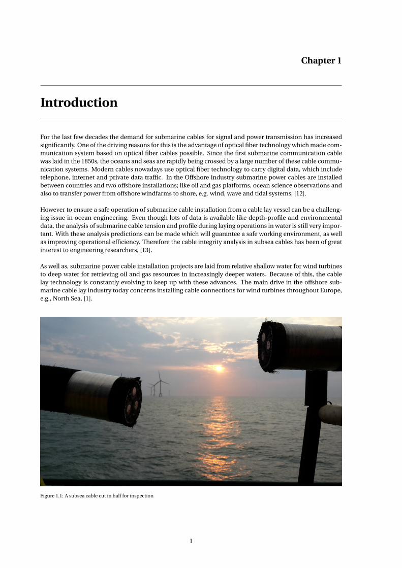
For the last few decades the demand for submarine cables for signal and power transmission has increasedsignificantly. One of the driving reasons for this is the advantage of optical fiber technology which made com-munication system based on optical fiber cables possible. Since the first submarine communication cablewas laid in the 1850s, the oceans and seas are rapidly being crossed by a large number of these cable commu-nication systems. Modern cables nowadays use optical fiber technology to carry digital data, which includetelephone, internet and private data traffic. In the Offshore industry submarine power cables are installedbetween countries and two offshore installations; like oil and gas platforms, ocean science observations andalso to transfer power from offshore windfarms to shore, e.g. wind, wave and tidal systems, [12].
However to ensure a safe operation of submarine cable installation from a cable lay vessel can be a challeng-ing issue in ocean engineering. Even though lots of data is available like depth-profile and environmentaldata, the analysis of submarine cable tension and profile during laying operations in water is still very impor-tant. With these analysis predictions can be made which will guarantee a safe working environment, as wellas improving operational efficiency. Therefore the cable integrity analysis in subsea cables has been of greatinterest to engineering researchers, [13].
As well as, submarine power cable installation projects are laid from relative shallow water for wind turbinesto deep water for retrieving oil and gas resources in increasingly deeper waters. Because of this, the cablelay technology is constantly evolving to keep up with these advances. The main drive in the offshore sub-marine cable lay industry today concerns installing cable connections for wind turbines throughout Europe,e.g., North Sea, [1].
Figure 1.1: A subsea cable cut in half for inspection
1
2 1. Introduction
1.1. Tideway Offshore SolutionsTideway has specialized knowledge, experience and techniques required for the installation of submarinepower cables, rock placement, seabed preparation, landfall construction, offshore dredging and deep seaharvesting.Tideway Offshore Solutions (TW) executes its offshore activities with several vessels; TidewayRollingStone(TRS), Flinstones(FS), Seahorse(SH), and Livingstone (LVS) (under construction). The subma-rine power cable installation is executed using a cable lay vessel equipped with a cable-lay system. Thisactivity is considered the core of the MSc Thesis.
1.2. Problem DescriptionConsider a submarine cable being installed on the seabed between an offshore platform and onshore con-struction. During installation operations if an unexpected high wave is encountered due to a peak wave, hightension fluctuations can occur in the submarine cable and possible exceed the allowable limits of the cable.It is therefore very important to investigate such effects to predict the influences on the cable during installa-tion at sea in a safe manner.
With development in the offshore field, cables are required to be installed at much greater depth comparedto a decade ago. This increases the importance of installation analysis of the cables to be carried out accu-rately, such that the installation is done in a safe manner and at the highest workability possible. Also withincreasing complexity of offshore cable installation and the desire for higher workability, the investigation ofimproving cable installation for safety, operational and commercial value was deemed necessary. In orderto increase the operational limit of the vessel during cable installation, the investigation into improvementsystems was desired.
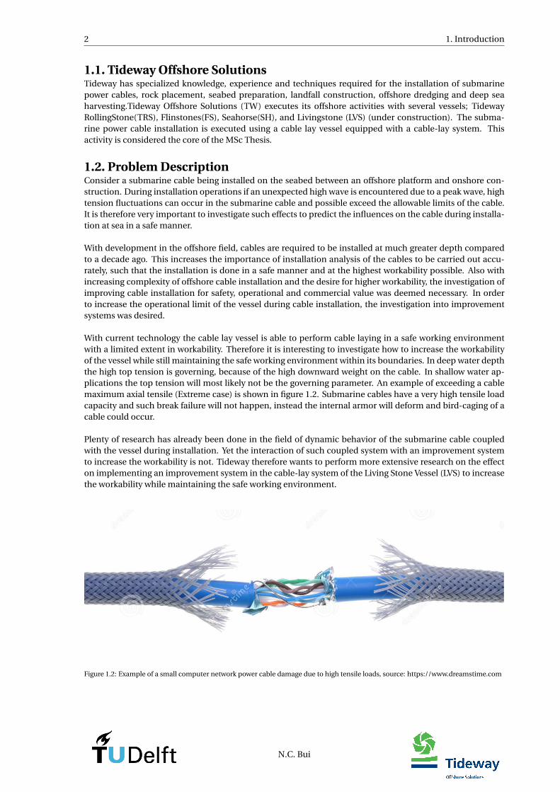
With current technology the cable lay vessel is able to perform cable laying in a safe working environmentwith a limited extent in workability. Therefore it is interesting to investigate how to increase the workabilityof the vessel while still maintaining the safe working environment within its boundaries. In deep water depththe high top tension is governing, because of the high downward weight on the cable. In shallow water ap-plications the top tension will most likely not be the governing parameter. An example of exceeding a cablemaximum axial tensile (Extreme case) is shown in figure 1.2. Submarine cables have a very high tensile loadcapacity and such break failure will not happen, instead the internal armor will deform and bird-caging of acable could occur.
Plenty of research has already been done in the field of dynamic behavior of the submarine cable coupledwith the vessel during installation. Yet the interaction of such coupled system with an improvement systemto increase the workability is not. Tideway therefore wants to perform more extensive research on the effecton implementing an improvement system in the cable-lay system of the Living Stone Vessel (LVS) to increasethe workability while maintaining the safe working environment.
Figure 1.2: Example of a small computer network power cable damage due to high tensile loads, source: https://www.dreamstime.com
N.C. Bui
1.3. Problem Statement 3
1.3. Problem StatementThe problem is defined as:
"The increasing demand for offshore wind energy and offshore cable installation is creating a desire for higherworkability in a safety, operational and commercial value"
1.4. Research ObjectivesIn order to have a successful marine operations, a good understanding of the dynamic behavior of the ca-ble structure, vessel, improvement system and environmental condition is required. The main focus of thisThesis will be to develop a stable model for subsea cable installation for various input conditions. Addition-ally different possibilities of improvement systems will be evaluated to increase the workability during cableinstallation. Simulations are performed for different water depths, significant wave heights, wave headingsand different cable properties. A 3D non-linear time domain model based on exact kinematics is used forthe numerical modeling of the submarine cable dynamics. The static and dynamics results are acquired byanalysis and simulations in a software called OrcaFlex. Below are proposed the main and sub objectives ofthe MSc thesis to be achieved.
"To develop a detailed model for dynamic analysis of subsea cables during installation and investigate theeffect of the different improvement systems to increase the workability"
1.4.1. Sub-Objectives1. Determine and study on the influence of the environmental and hydrodynamic loads on the system.
2. Develop a morphological overview based on the market research to mitigate for the high tension fluc-tuations in the cable.
3. Identify the factors that influence and contribute to the high fluctuating tensions in the submarinecables, with the focus on the vessel motions and cable integrity problems.
4. Develop simplistic analytical models of the improvement systems to determine the parameters inputfor the numerical model in OrcaFlex.
5. Create the final OrcaFlex models with improvement systems implemented to analyze the performanceof the improvement systems.
6. Develop and analyze the workability of the improvement systems in a full dynamic 3-hour simulation,to see whether it has the desired results compared to the non-improvement systems.
N.C. Bui
4 1. Introduction
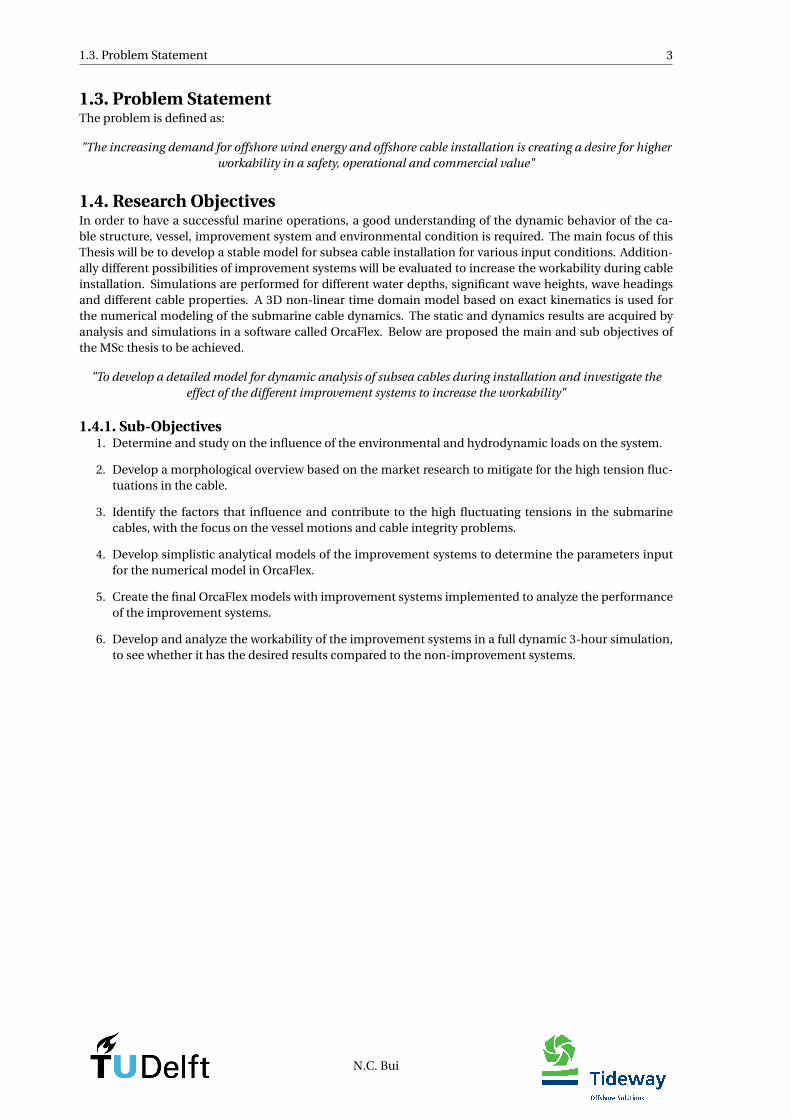
1.5. Approach of the projectTo achieve the main objective of the MSc Thesis topic, the research study can be evaluated into 3 differentstages. Figure 1.3 illustrates the approach that is used in this MSc Thesis report.
The first stage is to develop analytical models of the improvement systems with as main purpose to find thecontroller initial guess PID-Parameters. The improvement systems have been chosen based on a morpholog-ical overview developed and are actively controlled. In the analytical model the systems are assumed to bepositioned controlled as a single linear spring-mass-damper system of 1-Degree of Freedom (DOF). The ex-ternal forces acting on the systems are considered static. By use of a closed-loop-system with a feedback loopand Proportional-Integral-Derivative (PID)-Controller, a critical damped system can be developed to obtainthe initial guess PID-Parameters.
The second stage is to develop numerical models in OrcaFlex of the improvement systems which are per-forming with the same capability as the design criteria. In the numerical models the systems are influencedin the 6-DOF by dynamic forces like the vessel response and cable tensions. For an active control, the PID-Parameters found in the analytical model are used as initial guess PID-Parameter input to the PID-controllerexternal function in OrcaFlex. Two different controlling actions are evaluated, a force control and positioncontrol. Further tuning inside OrcaFlex is required to obtain the maximum system performance.
In the final stage of the approach, the final improvement systems developed in OrcaFlex are analyzed forresults for a full workability analysis. This means in all directions and different significant wave heights andperiods. The results will be analyzed for how much the cable integrity design conditions have been improvedand conclusions will be made based on the influence of such system during cable-laying for deep and shallowwaterdepths.
Figure 1.3: Approach of the MSc Thesis divided into three main steps; Analytical Model, Numerical model and results
N.C. Bui
Chapter 2
Offshore cable installation
This chapter provides an insight into the cable lay vessel(dimensions), cable lay methods(normal installation)and required cable lay equipment.
2.1. Living Stone vessel"Tideway Offshore Solutions is currently building the world’s most advanced subsea cable installation/trench-ing vessel ’Living Stone’. The vessel is equipped with two turntables below deck, each having a 5,000 tons ca-ble capacity. Together the turntables can carry and transport more than 200 km of cable that can be installedin a single trip. Ample deck space of 3,500 m2 facilitates a revolutionary cable handling system with innova-tive and reliable cable handling tools for cable ends, connections and cable protection systems. Furthermore,the ‘Living Stone’ can be equipped with a third carrousel above deck with an additional load capacity of 2,000tons and a 600 tons crane. A system developed in-house by Tideway enables the ‘Living Stone’ to install ca-bles faster and more efficiently in longer lengths and with less offshore joints than any other cable installationvessel. The vessel will serve transport and installation projects as well as offshore power cable installations,interconnectors for the future European Supergrid amongst others.
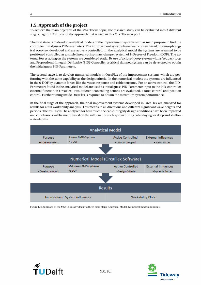
The ‘Living Stone’ features DP3 (Dynamic Positioning 3) capability and has been designed as an environ-mentally friendly vessel with dual fuel engines with LNG being its prime fuel. The ‘Living Stone’ has a GreenPassport and the Clean Design Notation awarded to owners and operators who choose to design and oper-ate their vessels in an environmentally sustainable approach". The information above is cited from a pressrelease about the ’Living Stone’ by DEME[10]. Below in the figure 2.1 shows an illustration of the profile ofthe vessel and table 2.1 gives the vessel properties. The Tideway vessel structure properties and RAOs areobtained from an analysis done in AQWA [7], [4].
Figure 2.1: Livingstone vessel profile
Length overall, Loa - [m] Depth(moulded), D - [m]Length between perpendiculars, Lpp - [m] Operational draught, T - [m]Breadth(moulded),B - [m] Ship maximum speed, V - [knots]
Table 2.1: Living Stone vessel properties, source:[7]
5
6 2. Offshore cable installation
2.2. Cable Lay MethodsSubmarine cable installation is basically deploying the cable from the cable lay vessel onto the seabed floor.This is done while the vessel is moving with a specific velocity forwards and the cable is payed-out simulta-neously by the tensioner system. After the cable is placed on the seabed, it will need to be protected againstdangerous hazards. The risk of damage is minimized and prevented of impact, by burial of the cables at a safedepth. The cable can be laid directly into the trench or the burial of cables can be done by jetting machines.Jetting machines uses a high pressure jet to increase the pore pressure. As result, the weight of the cable willcause it to bury itself. Also burial can be achieved by ploughing. In this method the cable is placed in a trenchopened by a plough and back-filled by a plough mechanism. In short, it is very important to maintain thecable integrity and fulfill the tight lay tolerance during operations.
In this section the different cable lay installation types, subsea power cable projects, subsea cable propertiesand horizontal or semi-vertical cable lay is studied and explained. All the cable lay method information isobtained from a cable lay guideline written by Tideway Offshore Solutions[11] and the DNV-RP-J301[11].
2.2.1. Cable-Lay installation StagesThere are several types of installation possibilities, and every project requires its own type of installation. Firstthere is Starting Cable installation by connecting the cable to the 1st end, next is the normal cable installation,Ending cable installation by connecting the cable to the 2nd end and at last the cable is trenched to protectit from dangerous hazards. In this MSc Thesis the focus is only on "cable installation type" with a normalinstallation. Below are the steps listed of subsea cables during "normal Installation" operations,
Normal Installation
1. Preparations on board Cable Lay VesselOfficial checks of the documentation and too see if the equipment is working properly.
2. Verify Cable Touchdown PositionAfter the preparations on the vessel, the subsea cable is verified if the configuration is in line with thedynamic analysis. Checks are done on the layback length, touch-down-point, top tension, and depar-ture angle, to maintain the cable s integrity. The lateral cable position and its position regarding theplanned route is important to maintain the cable’s tight lay tolerance.
3. Start/Continue Cable InstallationAfter approval of previous steps the cable lay vessel can start tracking a planned course and speedaccording to the Offshore Installation Manager(OIM). Simultaneously with the speed of the vessel, thetensioner pays out the subsea cable with a speed depending on the mode of the tensioner. The cablestorage system works together with the tensioner as a complete system. During installation all cableparameters should be monitored constantly and accurately. These are explained in Chapter 3.
4. Verify Cable position on seabedAfter installation of the subsea cable on the seabed, the position of the cable along the route is verifiedif it is within allowable tolerance. If the position of the subsea cable is accepted to be within allowabletolerance, the cable-lay can continue. In case the subsea cable is not within allowable tolerance, thesubsea cable must be relocated.
2.2.2. Subsea power cable projectsThe type of subsea cable to be installed and the choice of cable installation equipment are based on the ex-pected scope of work. The expected scope of work can either be in shallow or deep waterdepths, calm orrough sea states and type cable between onshore and on/off-shore structure. Below are the different typesof cable installation project indicated, each with its own different scope of work. The information is partyobtained from the Offshore Wind Program Board, [8].
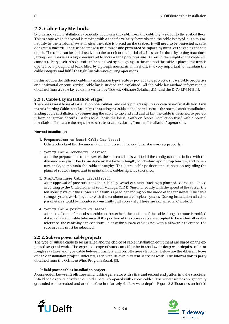
Infield power cables installation projectA connection between 2 offshore wind turbine generator with a first and second end pull-in into the structure.Infield cables are relatively small in diameter compared with export cables. The wind turbines are generallygrounded to the seabed and are therefore in relatively shallow waterdepth. Figure 2.2 illustrates an infield
N.C. Bui
2.2. Cable Lay Methods 7
power cable connection between two wind turbines offshore with the subsea cable trenched into the seabed.Cables between three offshore structures is called an inter line.
Figure 2.2: An infield cable connected between two offshore wind turbine structures. The cable is buried beneath the seabed
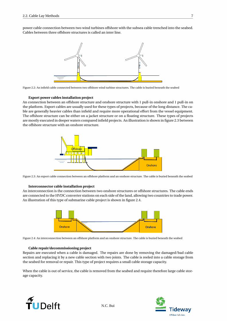
Export power cables installation projectAn connection between an offshore structure and onshore structure with 1 pull-in onshore and 1 pull-in onthe platform. Export cables are usually used for these types of projects, because of the long distance. The ca-ble are generally heavier cables than infield and require more operational effort from the vessel equipment.The offshore structure can be either on a jacket structure or on a floating structure. These types of projectsare mostly executed in deeper waters compared infield projects. An illustration is shown in figure 2.3 betweenthe offshore structure with an onshore structure.
Figure 2.3: An export cable connection between an offshore platform and an onshore structure. The cable is buried beneath the seabed
Interconnector cable installation projectAn interconnection is the connection between two onshore structures or offshore structures. The cable endsare connected to the HVDC converter stations on each side of the land, allowing two countries to trade power.An illustration of this type of submarine cable project is shown in figure 2.4.
Figure 2.4: An interconnection between an offshore platform and an onshore structure. The cable is buried beneath the seabed
Cable repair/decommissioning projectRepairs are executed when a cable is damaged. The repairs are done by removing the damaged/bad cablesection and replacing it by a new cable section with two joints. The cable is reeled into a cable storage fromthe seabed for removal or repair. This type of project requires a small cable storage capacity.
When the cable is out of service, the cable is removed from the seabed and require therefore large cable stor-age capacity.
N.C. Bui
8 2. Offshore cable installation
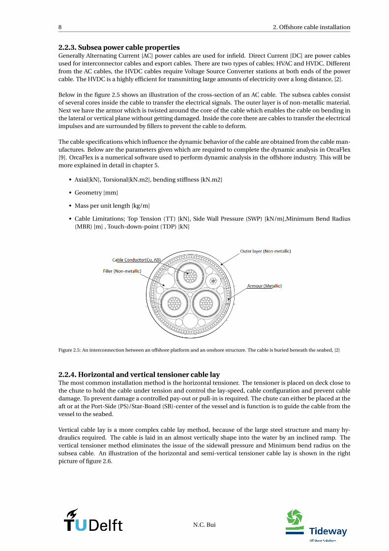
2.2.3. Subsea power cable propertiesGenerally Alternating Current [AC] power cables are used for infield. Direct Current [DC] are power cablesused for interconnector cables and export cables. There are two types of cables; HVAC and HVDC. Differentfrom the AC cables, the HVDC cables require Voltage Source Converter stations at both ends of the powercable. The HVDC is a highly efficient for transmitting large amounts of electricity over a long distance, [2].
Below in the figure 2.5 shows an illustration of the cross-section of an AC cable. The subsea cables consistof several cores inside the cable to transfer the electrical signals. The outer layer is of non-metallic material.Next we have the armor which is twisted around the core of the cable which enables the cable on bending inthe lateral or vertical plane without getting damaged. Inside the core there are cables to transfer the electricalimpulses and are surrounded by fillers to prevent the cable to deform.
The cable specifications which influence the dynamic behavior of the cable are obtained from the cable man-ufactures. Below are the parameters given which are required to complete the dynamic analysis in OrcaFlex[9]. OrcaFlex is a numerical software used to perform dynamic analysis in the offshore industry. This will bemore explained in detail in chapter 5.
• Axial[kN], Torsional[kN.m2], bending stiffness [kN.m2]
• Geometry [mm]
• Mass per unit length [kg/m]
• Cable Limitations; Top Tension (TT) [kN], Side Wall Pressure (SWP) [kN/m],Minimum Bend Radius(MBR) [m] , Touch-down-point (TDP) [kN]
Figure 2.5: An interconnection between an offshore platform and an onshore structure. The cable is buried beneath the seabed, [2]
2.2.4. Horizontal and vertical tensioner cable layThe most common installation method is the horizontal tensioner. The tensioner is placed on deck close tothe chute to hold the cable under tension and control the lay-speed, cable configuration and prevent cabledamage. To prevent damage a controlled pay-out or pull-in is required. The chute can either be placed at theaft or at the Port-Side (PS)/Star-Board (SB)-center of the vessel and is function is to guide the cable from thevessel to the seabed.
Vertical cable lay is a more complex cable lay method, because of the large steel structure and many hy-draulics required. The cable is laid in an almost vertically shape into the water by an inclined ramp. Thevertical tensioner method eliminates the issue of the sidewall pressure and Minimum bend radius on thesubsea cable. An illustration of the horizontal and semi-vertical tensioner cable lay is shown in the rightpicture of figure 2.6.
N.C. Bui
2.3. Cable installation equipment 9
Figure 2.6: Left you see an illustration of a horizontal tensioner cable lay vessel, source: Germany: NSW Charters Cable Laying Vessel MVAura. Right illustration you see a semi-vertical tensioner cable lay vessel, source: Subsea 7 reel-lay vessel seven Oceans.
2.3. Cable installation equipmentThis section contains general information about cable lay system equipment required to operate and executea cable installation. The entire structure generally consist of the cable storage, cable highway, cable tensionerand chute. An example of a deck-layout is illustrated in figure 2.7. The type of subsea cable to be installed andthe choice of equipment are based on the expected scope of work. All the cable lay equipment information isobtained from a cable lay guideline written by Tideway Offshore Solutions[11] and the DNV-RP-J301[11].
Figure 2.7: Top view of a Living Stone with an example of how the cable lay deck-layout could look like
2.3.1. Cable storageThere exist various systems on the market to storage a large amount of submarine cable on a vessel. Infieldpower cables are relatively lighter than export and interconnector cables and may therefor be split in sectionsand stored onto separate systems. Export and interconnector cables on the other hand are relatively large inlength and heavy in weight and preferred not to be split in sections. The cables are loaded onboard by spool-ing the cable onto a storage system, lifting a pre-loaded storage system onboard or with skidding operationsof a full storage system. Each cable storage system has its own advantages and disadvantages which are listedbelow.
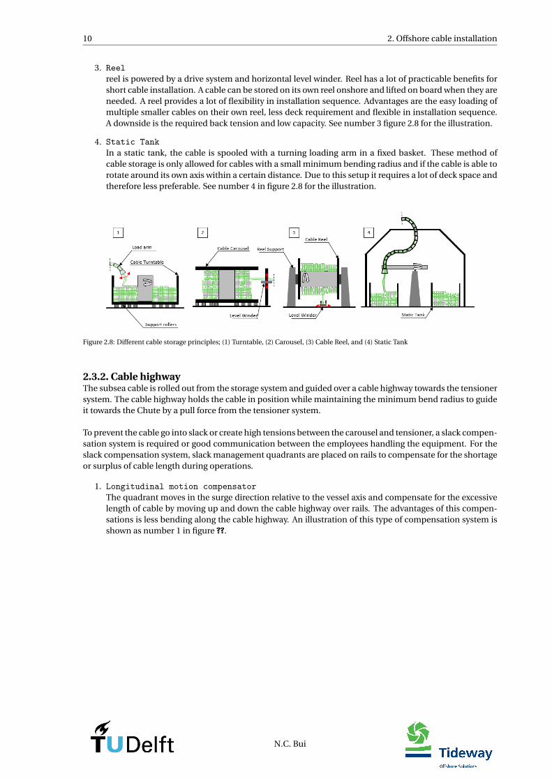
1. TurntableDifferent from the carousel, a turntable rotate the storage basket where the cable is spooled onto, eachlayer is stored on top of the layer before. Advantages of this system are the storage of multiple cablesand evenly spread deck load. A disadvantage of this system are the turning speed of the turntable mustbe kept under tension by continuously adjusting and the cable needs to enter the turntable tensionlessto prevent pulling the outer layer inside. See number 1 in figure 2.8 for the illustration.
2. CarouselThe carousel is circular construction where the cable is spooled around a vertical core (layer by layer),beginning from the inner-core towards the outer core. Advantages are the large storage capacity andeasy loading. A disadvantage is that the cable must always be kept under tension to prevent it fromsliding off the vertical core. See number 2 in figure 2.8 for the illustration.
N.C. Bui
10 2. Offshore cable installation
3. Reelreel is powered by a drive system and horizontal level winder. Reel has a lot of practicable benefits forshort cable installation. A cable can be stored on its own reel onshore and lifted on board when they areneeded. A reel provides a lot of flexibility in installation sequence. Advantages are the easy loading ofmultiple smaller cables on their own reel, less deck requirement and flexible in installation sequence.A downside is the required back tension and low capacity. See number 3 figure 2.8 for the illustration.
4. Static TankIn a static tank, the cable is spooled with a turning loading arm in a fixed basket. These method ofcable storage is only allowed for cables with a small minimum bending radius and if the cable is able torotate around its own axis within a certain distance. Due to this setup it requires a lot of deck space andtherefore less preferable. See number 4 in figure 2.8 for the illustration.
Figure 2.8: Different cable storage principles; (1) Turntable, (2) Carousel, (3) Cable Reel, and (4) Static Tank
2.3.2. Cable highwayThe subsea cable is rolled out from the storage system and guided over a cable highway towards the tensionersystem. The cable highway holds the cable in position while maintaining the minimum bend radius to guideit towards the Chute by a pull force from the tensioner system.
To prevent the cable go into slack or create high tensions between the carousel and tensioner, a slack compen-sation system is required or good communication between the employees handling the equipment. For theslack compensation system, slack management quadrants are placed on rails to compensate for the shortageor surplus of cable length during operations.
1. Longitudinal motion compensatorThe quadrant moves in the surge direction relative to the vessel axis and compensate for the excessivelength of cable by moving up and down the cable highway over rails. The advantages of this compen-sations is less bending along the cable highway. An illustration of this type of compensation system isshown as number 1 in figure ??.
N.C. Bui
2.3. Cable installation equipment 11
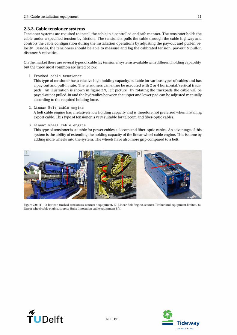
2.3.3. Cable tensioner systemsTensioner systems are required to install the cable in a controlled and safe manner. The tensioner holds thecable under a specified tension by friction. The tensioners pulls the cable through the cable highway andcontrols the cable configuration during the installation operations by adjusting the pay-out and pull-in ve-locity. Besides, the tensioners should be able to measure and log the calibrated tension, pay-out & pull-indistance & velocities.
On the market there are several types of cable lay tensioner systems available with different holding capability,but the three most common are listed below.
1. Tracked cable tensionerThis type of tensioner has a relative high holding capacity, suitable for various types of cables and hasa pay-out and pull-in rate. The tensioners can either be executed with 2 or 4 horizontal/vertical track-pads. An illustration is shown in figure 2.9, left picture. By rotating the trackpads the cable will bepayed-out or pulled-in and the hydraulics between the upper and lower pad can be adjusted manuallyaccording to the required holding force.
2. Linear Belt cable engineA belt cable engine has a relatively low holding capacity and is therefore not preferred when installingexport cable. This type of tensioner is very suitable for telecom and fiber-optic cables.
3. Linear wheel cable engineThis type of tensioner is suitable for power cables, telecom and fiber-optic cables. An advantage of thissystem is the ability of extending the holding capacity of the linear wheel cable engine. This is done byadding more wheels into the system. The wheels have also more grip compared to a belt.
Figure 2.9: (1) 10t baricon tracked tensioners, source: 4equipment, (2) Linear Belt Engine, source: Timberland equipment limited, (3)Linear wheel cable engine, source: Hulst Innovation cable equipment B.V.
N.C. Bui
12 2. Offshore cable installation
Tensioner operation modesThe tensioner systems are able to operate in two different control modes; Speed Mode Tension Mode, andRender mode, [6]. Each mode is used for different purposes and it also influences the required cable equip-ment. Below are only the modes listed which are of importance in this MSc Thesis;
• Speed ModeThe speed mode is the operational mode to control the speed. This mode is used when the cable instal-lation is preferred to be controlled manually. The operator can adjust the pay-out or pull-in velocities,based on the actual measured tension at the tensioner system load cells. This type of operation makesthe cable sensitive for high peak tensions, because of human responds delay.
• Tension ModeDuring laying operations when the tensioner system is in tension mode, the system automatically pays-out faster when the target value is exceeded and pays-out slower when the tension is below the value.In this mode the torque and speed can be automatically adjusted by active control.
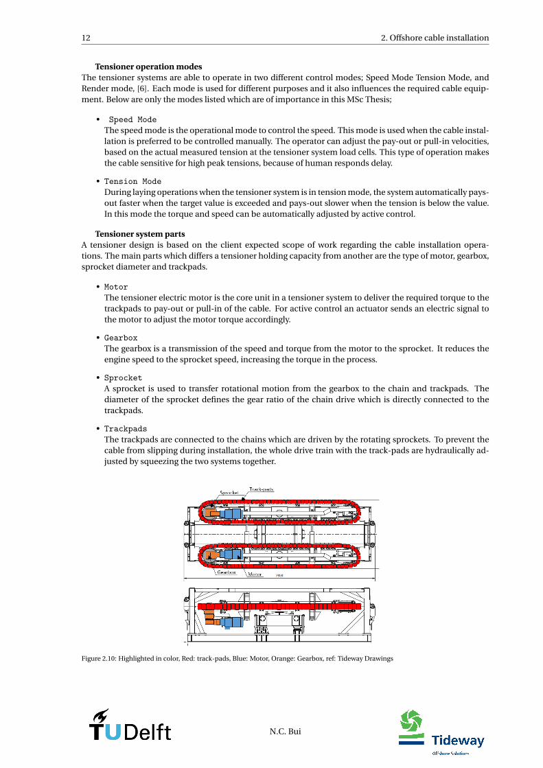
Tensioner system partsA tensioner design is based on the client expected scope of work regarding the cable installation opera-tions. The main parts which differs a tensioner holding capacity from another are the type of motor, gearbox,sprocket diameter and trackpads.
• MotorThe tensioner electric motor is the core unit in a tensioner system to deliver the required torque to thetrackpads to pay-out or pull-in of the cable. For active control an actuator sends an electric signal tothe motor to adjust the motor torque accordingly.
• GearboxThe gearbox is a transmission of the speed and torque from the motor to the sprocket. It reduces theengine speed to the sprocket speed, increasing the torque in the process.
• SprocketA sprocket is used to transfer rotational motion from the gearbox to the chain and trackpads. Thediameter of the sprocket defines the gear ratio of the chain drive which is directly connected to thetrackpads.
• TrackpadsThe trackpads are connected to the chains which are driven by the rotating sprockets. To prevent thecable from slipping during installation, the whole drive train with the track-pads are hydraulically ad-justed by squeezing the two systems together.
Figure 2.10: Highlighted in color, Red: track-pads, Blue: Motor, Orange: Gearbox, ref: Tideway Drawings
N.C. Bui

2.3. Cable installation equipment 13
2.3.4. ChuteThe chute is used to guide the subsea cable safely overboarding from the cable lay vessel towards the seabed.Its design depends on the cable limitation and installation type. Two types of chute designs are listed below.
• Flared ChuteA flared chute has a v-shape open channel to guide the subsea cable (see number 1 on figure 2.11).Having a flared chute enables freely circular rotation of the vessel.
• Straight ChuteThe straight chute is a very simple and easy design(Illustrated in figure 2.11 as number 2). The disad-vantage is the circular rotation of the vessel compared to a flared chute. A straight chute can also beconstructed with rollers for a frictionless chute (number 3).
Figure 2.11: These are pictures of existing Chute types, Flared Chute(1), Straight Chute fixed(2), Straight Chute Rotating wheel(3), [11]
2.3.5. Possible improvement systemsA study is done on the possible systems to improve the workability of the vessel during cable installation op-erations. Several systems have been found and are listed and elaborated below.
(1) Constant Tension System, Constant Tension (CT)A constant tension system is simply the ’Tension mode’ from a tensioner system. The tension is compen-sated for by active control of the measured force by load cells. The actual measured tension at the load cellsare compared with the target force value and as output of the system the trackpads of the system will rotatewith a specified pay-out or pull-in velocity. To use such system it requires either slack-management or goodcommunication between the carousel and tensioner operators. An illustration to set the ’Tension mode’ isshown in the left picture of figure 2.12. This type of improvement system indirectly reduces the cable mo-tions and result in lower tension fluctuation in the cable. In the PID Setup Control screen different parame-ters can be specified such as the Gain, Integral, Derivative. These parameters will be elaborated in Chapter[4].
Figure 2.12: PID Setup Screen of a tensioner on Tension Control, [6].
(2) Heave Compensated Chute, HCCThe HCC system is designed and constructed by KCI[5]. It is a semi-active system to compensate for the heavedisplacement by force control of the piston length. Technical details about the construction or dynamics arenot given, only an artist impression and picture is found for the rough estimations.
N.C. Bui

14 2. Offshore cable installation
Figure 2.13: Left you see a realistic HCC build on a vessel and right you see an artist impression of the HCC, [5]
(3) Catenary cable stabilizer with depressorThe catenary cable stabilizer is a concept design of Subsea7 to improve the catenary shape during operations,[3].The depressor on the catenary will act as an weight element with a bell-mouth on both ends and is loweredfrom the vessel by two winches towards the TDP. The main purpose of this improvement system is to con-trol the TDP of the cable. This results in a more controlled layback length of the cable and reduces the peaktensions at the TDP. This type of improvement system is especially of interest for deep waterdepth projects,uneven seabed, long cables, strong current and where the length of the Remotely Operating Vehicle (ROV)reaches its limit.
Figure 2.14: Depressor, left figure shows a realistic build depressor on a vessel, and right when the depressor is deployed along the cablecatenary line.[3]
(4) Cable installation PS/SB CenterThe chute can be placed at the aft or PS/SB center of the vessel. The main advantage of a PS/SB center loca-tion compared to the aft location is the overall reduction of the heave and pitch motions during operations.This solution is illustrated in figure 2.15.
Figure 2.15: Location of the chute at the aft-SB and center-PS of the vessel.
N.C. Bui
Chapter 3
General Cable Lay mechanics
This chapter gives a description about the cable mechanical problems in general and influences due to en-vironmental loads, hydrodynamic loads and vessel response on the cable. First the cable lay definitions areexplained then the caternary equations are presented. These will be used in the analytical models to definethe static tension in the cable. After, the cable integrity design conditions are presented and explained abouttheir occurrence and where they are influenced by. Two improvement systems are presented for further anal-ysis. For the investigation of environmental loads and hydrodynamic loads only waves are taken into accountto determine the particle velocity profile, wave spectrum, drag and inertia coefficient. Furthermore the vesselresponse calculations are presented to calculate the maximum heave motion of the chute location. These areall calculations to define the input parameters for the analytical and numerical models.
The content of this chapter is confidential. Contact the author or company for detailed informa-tion.
3.1. Cable Lay Definitions3.2. Cable Installation Loads3.2.1. Static Calculations3.2.2. Dynamic Calculations
3.3. Cable Integrity Design conditions3.4. Cable motions3.4.1. Tension fluctuations: Analytically explained3.4.2. Tension fluctuations: Numerically simulated
3.5. Concept improvement system3.5.1. Improved system 1: CT Tensioner System3.5.2. Improved system 2: HCC System
3.6. Environmental Loads3.6.1. Fluid Particle Velocity from waves for analysis3.6.2. Wave spectra for analysis
3.7. Hydrodynamic Loads3.7.1. Drag Force3.7.2. Inertia Force
3.8. Operational loads3.8.1. Vessel Response equations3.8.2. Chute Heave response3.8.3. Chute maximum heave response
3.9. Chapter summary
15


Chapter 4
Analytical Analysis of Improvement Systems
This chapter outlines the analytical analysis of the improvement systems, tensioner system and HCC system.First is explained how an active controller works, second the analytical models are developed for furtheranalysis in chapter 6 to define the critical damped system PID-Parameters.
The content of this chapter is confidential. Contact the author or company for detailed informa-tion.
4.1. Control Theory4.1.1. Open-Loop-System4.1.2. Closed-Loop-System4.1.3. Transferfunction: General Theory4.1.4. PID-Controller Theory
4.2. Analytical Model: CT Tensioner System4.2.1. Tensioner System modeling4.2.2. Vessel response influences4.2.3. Cable static force influences4.2.4. Force actuator4.2.5. Equation of Motion: Tensioner system4.2.6. Transferfunction: CT Tensioner system
4.3. Analytical Model: Heave Compensated Chute System4.3.1. Motion compensated Cylinder modeling4.3.2. Vessel response influences4.3.3. Cable static force influences4.3.4. Force Actuator4.3.5. HCC System: Equation of Motion4.3.6. Transferfunction HCC System
4.4. Chapter summary
17


Chapter 5
Numerical Analysis of Improvement systems
This chapter contains general information about the software OrcaFlex, developed by Orcina. First are thegoverning OrcaFlex model objects discussed on their physical behaviour and interaction with other objects,with the main focus on the winch object. The winch object is used to physically model a tensioner systemto actively control the force and motion compensated cylinder to actively control the position in OrcaFlexsoftware. Before finalizing the final models, a simple model is developed in OrcaFlex and validated against arealistic project: "Thornton bank Project". The results for the validation can be found in Appendix D.6.2.
The content of this chapter is confidential. Contact the author or company for detailed informa-tion.
5.1. General OrcaFlex software description5.2. OrcaFlex Objects and external influences modeling5.2.1. Line Object5.2.2. Winch Object5.2.3. Shapes5.2.4. Vessel object; "Living Stone"
5.3. Simulation model: Static Analysis5.4. Simulation model: Dynamic Analysis5.4.1. Solution method5.4.2. Explicit solver5.4.3. Implicit solver5.4.4. Stages
5.5. OrcaFlex modeling: CT Model5.5.1. Modeling of the flared chute5.5.2. Modeling of the active force controlled tensioner system5.5.3. Final Mode: CT Model
5.6. OrcaFlex modeling: AHCC Model5.6.1. Modeling of the Chute Structure5.6.2. Modeling of the Frame Structure5.6.3. Modeling an active positioned controlled cylinder5.6.4. Final model: AHCC Model
5.7. Chapter summary
19

Chapter 6
Model Analysis: Tensioner System
The transferfunctions of the tensioner system and the PID-controller are determined in chapter[4]. These willbe used as input for the open and closed loop-system to analyze its stability and safety margin for a criticaldamped system. As result from the analysis from the analytical Tensioner system, a set of PID-parameters aredefined. These will be used as input for the External Function(PID-controller) of the numerical CT Model todevelop an active system in OrcaFlex and determine the operation efficiency of the winch object in OrcaFlex.
The analytical model and numerical model in OrcaFlex are two complete different systems, but only usingthe same set of initial guess PID-parameters. The main difference between the analytical and numericalmodel are the non-linearities included in the numerical model for the cable dynamics and vessel dynamics.Whereas the analytical model assumes the cable to be a static force and only exerted by the maximum vesselheave motions. Furthermore the numerical model, models the tensioner system by a massless spring anddamper system with coefficients set to OrcaFlex default values. The analytical model, models the tensionersystem as a mass-spring-damper system with input parameters for the mass, spring and damper coefficientsobtained from IHC SAS bv C.2.
Here will also be analyzed how the performance of the numerical tensioner system behave and if its able tobecome stable when using the initial guess parameters. Based on this analysis will be determined if furthertuning of the PID-Parameters inside OrcaFlex is required to obtain a performance which uses the full capacityof the system. At last the final model with the tuned PID-Parameters will be analyzed for its tensioner systembehavior, reduction of the cable motion and improvement if its able to keep the cable integrity values withinthe design conditions.
The content of this chapter is confidential. Contact the author or company for detailed informa-tion.
6.1. Analytical analysis6.1.1. System Response6.1.2. Open-loop-system6.1.3. Closed-loop-system6.1.4. Concluding remarks on analytical analysis: Tensioner system
6.2. Numerical CT Model Analysis: OrcaFlex software6.2.1. Tuned PID-Parameter analysis6.2.2. Tensioner system performance analysis6.2.3. Final Constant Tension System analysis
6.3. Chapter summary6.3.1. Analytical CT Model6.3.2. Numerical CT Model
21

Chapter 7
Model Analysis: Heave Compensated ChuteSystem
The transferfunctions of the HCC system and the PID-controller are determined in chapter[4]. These thetransferfunctions will be used as input for the open and closed loop-system to analytically model a positioncontrolled critical damped system system for its its stability and safety margin. Same approach as the ten-sioner system will be used to model the final numerical models PID-parameters. The PID-parameters fromthe analytical models are used as input for the numerical model in OrcaFlex (See chapter 6. In the numericalmodel the velocity of the piston length control is constantly adjusted to keep the actual chute end z-locationon its target height value.
The main difference between the analytical and numerical model are the included non-linearities in the nu-merical model for the cable dynamics and vessel dynamics. Whereas the analytical model assumes the cableto be a static force and only exerted by the maximum vessel heave motions. In the numerical model themotion compensated cylinder is developed as a massless spring and damper system with coefficients set toOrcaFlex default values. The analytical model develops the motion compensated cylinder as a mass-spring-damper system with input parameters for the mass, spring and damper coefficients obtained from BoschRexboth C.1.
The performance of the cylinder is analyzed in the numerical model analysis for its stability and how well itcan keep the chute-end location on its z location when using the initial PID-Parameters. If the chute is stilldeviating significantly from the target height and the system is not using the full capacity, the PID-Parametersare further tuned inside OrcaFlex. Furthermore the final model cylinder is analyzed for its performance, im-proving behavior and whether the cable integrity are below its design conditions
The content of this chapter is confidential. Contact the author or company for detailed informa-tion.
7.1. Analytical analysis7.1.1. System Response7.1.2. Open-loop-system7.1.3. Closed-loop-system7.1.4. Concluding remarks on analytical analysis: HCC system
7.2. Numerical HCC Model Analysis: OrcaFlex software7.2.1. Tuned PID-Parameter analysis7.2.2. Final Heave Compensated Chute System analysis
7.3. Chapter summary7.3.1. Analytical AHCC Model7.3.2. Numerical AHCC Model
23

Chapter 8
Workability Analysis CT Tensioner System andAHCC System
In this chapter the CT Model and AHCC Model are dynamically analyzed in irregular sea states for differentwave headings, waterdepths of 30 and 600[m]. significant wave heights with its corresponding peak periodobtained from the JONSWAP Spectrum in OrcaFlex software. The systems in the models are using the fullcapacity of the design criteria by setting the controller with the tuned PID-Controller.
A realistic case ’Johan Sverdrup Project’ is used to analyze the CT Model and AHCC Model for its workabilityduring cable lay installation operations. The case information can be found in Appendix [B.1]. The consid-ered case is about the installation of the HCDC Export cable between the onshore DVHC converter stationat Haugneset and the Johan Sverdrup Riser Platform. The platform is located at approximately 155[km] dis-tance from the coast of Stavanger. Through the subsea cable, a 100[MW] power is supplied from onshore tooffshore high voltage direct current module on the Riser Platform. The route from the onshore station to-wards the offshore Riser Platform, Johan Sverdrup has a depth which varies from 0 till approximately 600 [m].The deep waterdepth of 600[m] and shallow waterdepth of 30[m] is considered for the full dynamic analysis.
From this analysis should become clear which improvement system maintains the cable integrity within itsdesign condition for the highest possible sea state for deep and shallow waterdepths. The cable integritywill be analyzed and verified for the four criteria mentioned in Chapter [3], top tension, Side-Wall-Pressure,Touch-Down-Point and Minimum Bend Radius. At last a total workability plot will be developed.
The content of this chapter is confidential. Contact the author or company for detailed informa-tion.
8.1. General Model: Workability Analysis8.2. Workability CT Model Analysis8.2.1. CT Model: Top Tension of the cable
8.3. Workability HCC Model Analysis8.3.1. AHCC Model: Top Tension of the cable
8.4. Workability plots8.5. Chapter summary
25

Chapter 9
Conclusions
The main objective of this thesis was to develop a detailed model for dynamic analysis of a subsea cable dur-ing installation in OrcaFlex software and investigate the effect of the different improvement systems. Thiscould lead to an increased workability of the Living Stone during cable lay operations by maintaining thecable integrity design criteria(TT, SWP, TDP and MBR). First an analytical model was developed of the im-provement systems to control the position of the cable and chute of a linear SMD-System of only 1-DOF. Thepurpose of the analytical model is only to define the initial guess PID-Parameters used as input for the exter-nal function of the numerical model in OrcaFlex. Second the numerical CT and HCC models were developedin OrcaFlex. The CT Model actively controls the actual measured tension of the cable at the top and the HCCModel actively controls the actual measured heave displacement of the Chute end location. Inside OrcaFlexthe PID-Parameters are further tuned to guarantee the systems are performing according to the full capabilityof a real system. Finally it is of important the improvement systems can be used for different environmentalcases. The conclusion is divided into three parts; Analytical model, numerical model and the final results ofboth improvement systems. At the end final conclusions are drawn for the improvement system.
The content of this chapter is confidential. Contact the author or company for detailed informa-tion.
27


Chapter 10
Recommendations
From the conclusions, results and observations in this MSc Thesis, the following recommendations are sug-gested to obtain a more accurate workability plot and realistic performance of the systems.
The content of this chapter is confidential. Contact the author or company for detailed informa-tion.
29

Appendix A
Tideway Flinstone Vessel Visit: Cable Repairproject
The content of this chapter is confidential
31


Appendix B
Project cases
B.1. Project: Johan SverdrupThe content of this section is confidential
B.2. Project: Thornton BankThe content of this section is confidential
33


Appendix C
Product information
C.1. Hydraulic CylinderThe content of this section is confidential
C.1.1. Hydraulic Cylinder CalculatorThe content of this subsection is confidential
C.2. Tensioner SystemThe content of this section is confidential
C.3. Export Cable propertiesThe content of this section is confidential
C.4. Flared chute structureThe content of this section is confidential
C.5. Heave compensated Chute StructureThe content of this section is confidential
35

Appendix D
Model Analysis Sensitivity study’s
D.1. CT system DeadbandThe content of this section is confidential
D.2. CT system FrictionThe content of this section is confidential
D.3. HCC system FrictionThe content of this section is confidential
D.4. OrcaFlex FrictionThe content of this section is confidential
D.5. OrcaFlex Contact normal StiffnessThe content of this section is confidential
D.6. OrcaFlex Contact shear StiffnessThe content of this section is confidential
D.6.1. OrcaFlex Line segmentationThe content of this subsection is confidential
D.6.2. OrcaFlex model validationThe content of this subsection is confidential
37


Appendix E
Workability Analysis Results
E.1. General ModelThe content of this section is confidential
E.2. CT ModelThe content of this section is confidential
E.3. AHCC ModelThe content of this section is confidential
39


Appendix F
Morphological Overview decision making
F.1. ProcedureThe content of this section is confidential
F.2. Basic design criteriaThe content of this section is confidential
F.2.1. Partial Functions & Various possibilitiesThe content of this subsection is confidential
41

Appendix G
Chute port-side-center vessel
43


Appendix H
Transferfunction: Mitigation Solutions
H.1. Transferfunction: Tensioner SystemH.2. Transferfunction:Heave Compensated Chute System
45


Appendix I
External Function in Python: PID-Controller
I.1. CT Tensioner System External FunctionI.2. HCC System External Function
47


Bibliography
[1] Issue Date, International Cable, and Protection Committee. Submarine Power Cables, Lecture Note.(November), 2011.
[2] Det Norske Veritas. Subsea Power Cables in Shallow Water Renewable Energy Applications. TechnicalReport February, 2014.
[3] Renaud Gueret and Subhajit Lahiri. SPE 166565 Umbilical Lay In Challenging Environmental Condi-tions. (September):3–6, 2013.
[4] Revision History. SEAKEEPING ANALYSIS FOR A CABLE LAYER RAOs and Acceleration studies for twocable layer vessels designs under two different weather conditions, including moonpool effect and rolldamping analysis. 2015.
[5] Brian D Jeffs. Heave Compensated Chute. (October), 2004.
[6] MDL. 15 Tonne Electric Tensioner Operation and Maintenance Manual. (03), 2014.
[7] Construcciones Navales. Longitudianl Design Loads and Accelerations. 2015.
[8] Offshore Wind Programme Board. Overview of the offshore transmission cable installation process inthe UK. (September), 2015.
[9] Orcina. OrcaFlex Manual. 44(Version 9.1a):1–429, 2014.
[10] Press Release. PRESS RELEASE DEME launches the world ’ s most advanced subsea cable installation /trenching vessel ‘ Living Stone ’. 3(September 2016):2016–2018, 2017.
[11] Tideway offshore Solutions. Guideline cable lay operations. 2016.
[12] Submarinecablesystems. Submarine Cable System History, 2012. URL http://www.calcable.org/learn/history-of-cable/.
[13] Wikipedia. Submarine communications cable, 2016.
49


![Ropes for Subsea Cable Laying - brunton-shaw.com · [ BUOY & GRAPNEL ] Cable Laid combined (wire and natural fibre) ropes specially designed for Subsea Cable Laying duties Ropes for](https://img.pdfslide.us/doc/110x75/5e126c3ed43a5b3e643fb493/ropes-for-subsea-cable-laying-brunton-shawcom-buoy-grapnel-cable-laid.jpg)