Embed Size (px)
Citation preview
DI~CEMBnE 1D53 LA HOUILLE BLANCHE 873
Fan-shaped outletsPltOPESSOR. DR B. HELLsrl'ROl\1
nIHECTOH OF THE I:-iSTITUTION OF HYDHAULICS
THE HOYAL I:-iSTITUTE OF TECH:-iOLOGY, STOCKHOUI
Texte français, page 881
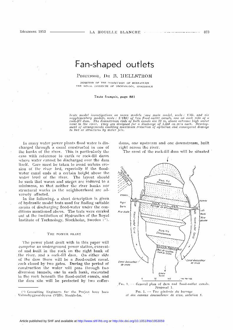
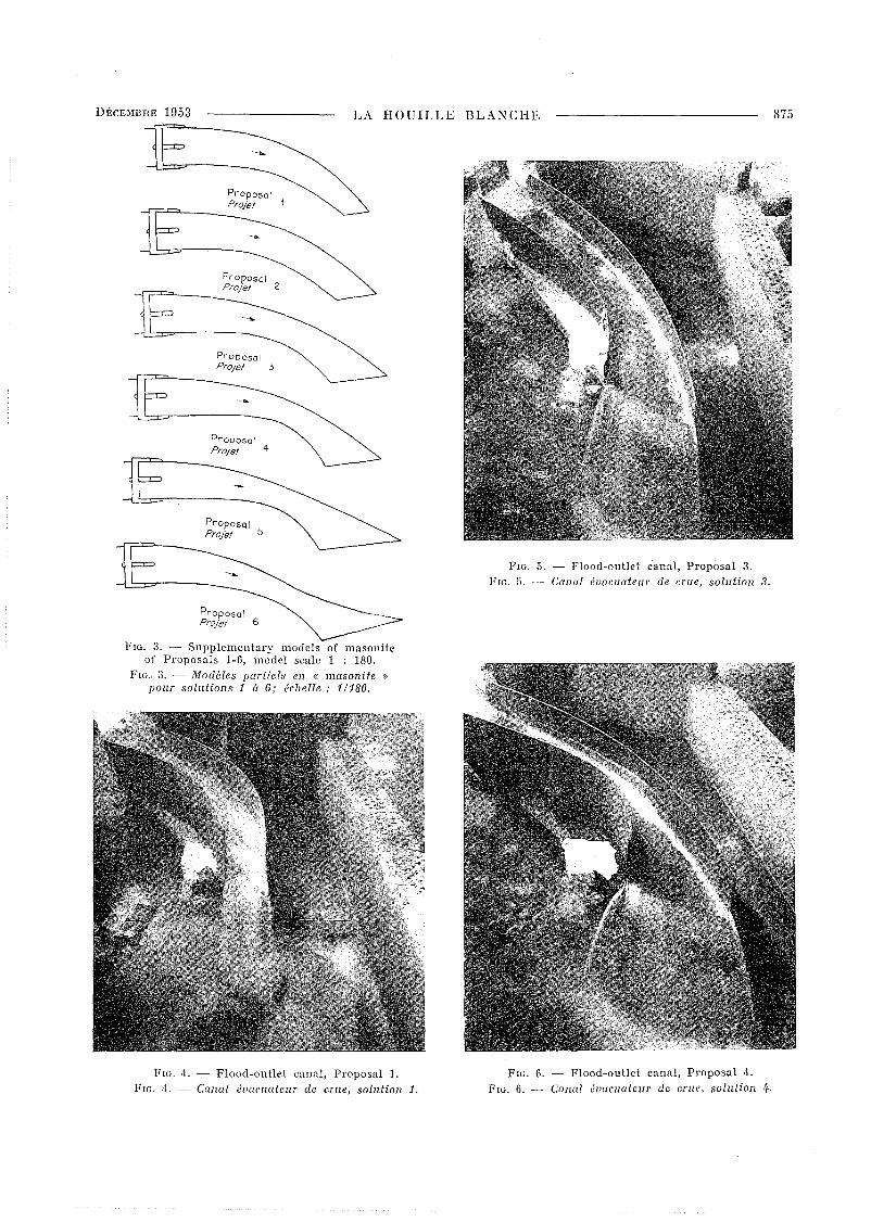
Scale model inuesUgations on seuen models (one main model, scale: 11(jO, and sixsupplementary models, scale : 11180) of two flood-OlIllet canals, one on each side of arock-fill dam. The downstrealll ends of both canals are 12 m, aboue e.Ttreme high lImierhuel in Ihe riuer. They are designed for a disc/wrge of 5,500 cII.mls eac/I. Deuelopment of arrangements enabling ma:I:imllm redlIclion of agitai ion and conseqlIcnt damageto bed or structlIres by water jets.
dams, one upstream and one downstream, huiltl'ight across the river.
The crest of the rock-Jill dam will he situated
1'1(,. 1. General plan of dam and j]Ood-olltlet canals.Proposai 1.
FIG. 1. - YlIe yénérale dll barrageel des canall.T éuaclwlclIrs de crlle, SOIIIlion 1.
\ Canal évacuateurde crues
EchelleScole
50 100 . 1~O Hètîes'--__'-- L'__----.J'
Right
Bank
Canal évacuateurJde crues
Rive droite
(') Consulting Engineers for the Project have heenVattenbyggnadshyran (VI3H), Stoekho]m.
In many ,vater power plants nood water is discharged through a canal constructed in one ofthe banks of the river. This is particularly thecase with reference to earth or rock-Jill damswhere water cannot be discharged over the damitsele Care must be taken to avoid serious erosion of the river bed, especially if the Hoodwater canal ends at a certain 11Cight above thewater level of the river. The layout shouldbe such that waves and surges are reduced to aminimum, so that neither the river hanks norstructural works in the neighhourhood are adversely afTected.
In the following, a short description is givenof hydraulic model tests used for Jinding suitahlemeans of discharging nood-water under the conclitions mentioned above. The tests were carriedout at the Institution of Hydraulics of the Royal'Institute of Technology, Stockholm, Sweden (*).
THE POWEH PLANT
The power plant dealt with in this paper willcomprise an underground power station, excavated and huilt in the rock on the right bank ofthe river, and a rock-Jill dam. On either sideof the dam there will be a nood-outJet canal,each cJosed hy two gates. During the period ofconstruction the water will pass through twodiversion tunnels, one in each hank, excavatedin the rock heneath the flood-outlet canals, andthe ciarll site will he protected hy two coffer-
Article published by SHF and available at http://www.shf-lhb.org or http://dx.doi.org/10.1051/lhb/1953059
874 LA HOUILLE BLANCHE DÉCEMBRE 1953
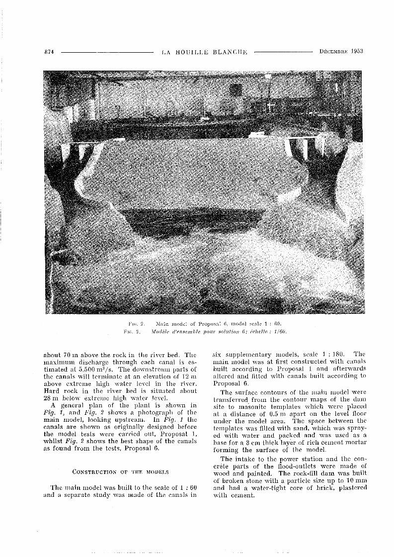
FIG. 2 - Main mode! of Proposa! li, mode! sca!e 1 : liO.
FH;. 2 - Modèle d'ensemble pOlir sollltion 6; érilelle : 1160.
about 70 m above the rock in the river bed. Themaximum discharge through each canal is estimated at 5,500 m 3/s. The downstream parts ofthe canals will terminate at an elevation of 12 mabove extreme high water level in the river.Hard rock in the river bed is situated about28 m below extreme high water level.
A general plan of the plant is shown inFig. 1, and Fig. 2 shows a photograph of themain model, looking upstream. In Fig. 1 thecanals are shown as originally designed beforethe model tests were carried out, ProposaI 1,whilst Fig. 2 shows the best shape of the canalsas found from the tests, ProposaI 6.
CONSTRUCTION OF THE l\IODELS
The main model was built to the scale of 1 : 60and a separate study was made of the canals in
six supplementary models, scale 1 : 180. Themain model was at first constructed with canalshuilt according to ProposaI 1 and afterwardsaltered and fitted \vith canals huilt according toProposaI 6.
The surface contours of the main model weretransferred from the contour maps of the damsite to masonite templates which were placedat a distance of 0.5 m apart on the level floorunder the model area. The space between thetemplates was filled with sand, which was sprayed \Vith water and packed and was used as ahase for a 3 cm thick layer of rich cement mortarfOl'ming the surface of the model.
The intake to the power station and the concrete parts of the flood-outlets were made ofwood and painted. The rock-fill dam was bumof broken stone ,vith a particle size up to 10 mmand had a water-tight core of brick, plasteredwith cement.
DÉCEMBHE 1953 LA HOUILLE BLANCHE 875
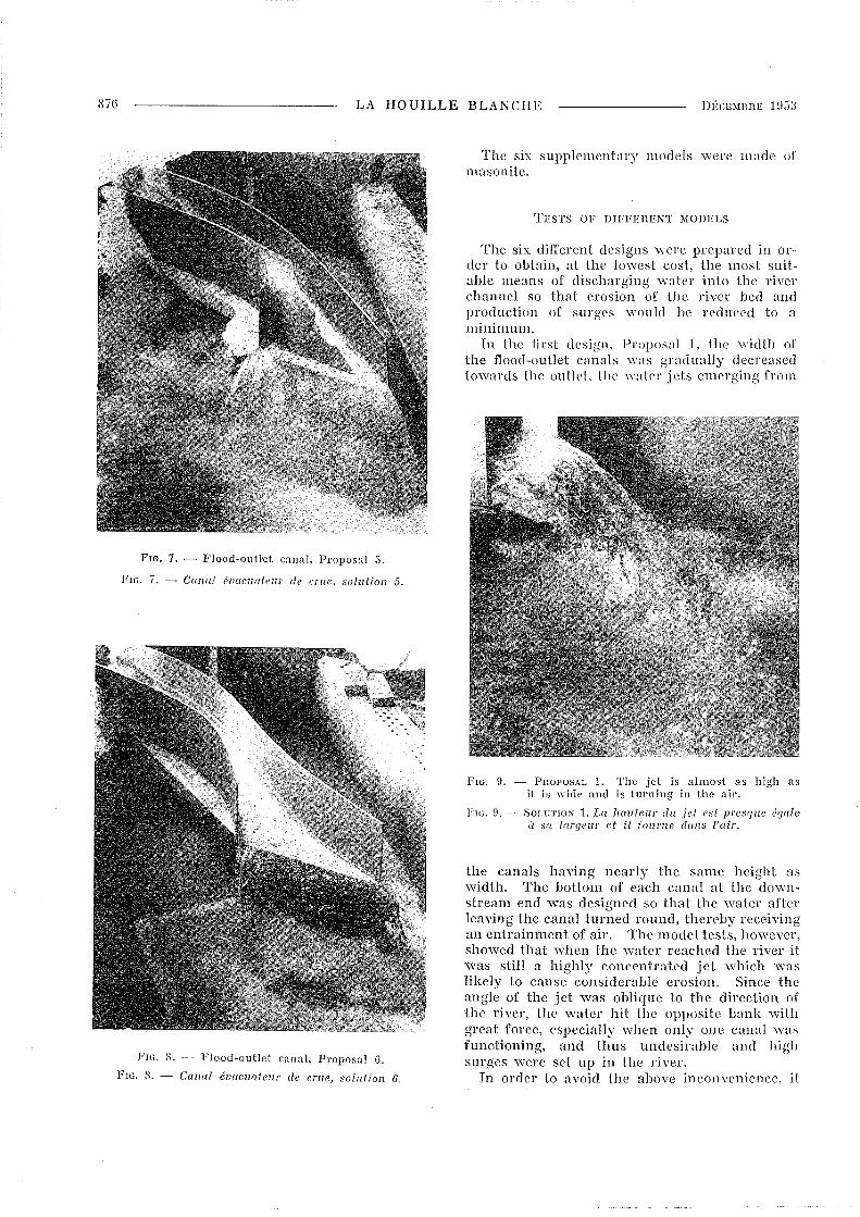
FIG. 5. - FJood-ouUet cana J, ProposaI 3.FIG. 5. -- Canal éuaczwtezzr de crue, solution 3.
PrOposaiProjet 5
ProposaiProjet
ProposaiProjet 3
ProposaiProjet-rr="'---__
ProposaiProjet 2-rr="'--__
ProposaiProjet 6
FIG. 3. Supplementary models of masoniteof ProposaIs 1-6, model scale 1 : 180.
FIG .. 3. - Modèles partiels en « masonite »pour solutions 1 il 6; échelle: 1/180.
FIG. 4. - Flood-ouUet canal, ProposaI 1.FIG. 4. - Canal évacuateur de crue, solution 1.
FIG. 6. - Flood-ouUet canal, ProposaI 4.FIG. 6. - Canal éuacuatezu de crue, solution 4.
S7G LA HOUILLE BLANCHE
FIG. 7. - Flood-ouUet canal, Proposal 5.
FIG. 7. - Cana! évacuatellr de crue, solution 5.
FI<>. 8. ---- Flood-outlet canal, Proposal 6.
FIG. 8. - Canal évacuateur de crlle, solution 6.
The six supplementary models were made ofmasonîte.
TESTS OF DIFFERENT MODELS
The six difIerent designs were prepared in 01'
der to obtain, at the lo,vest cost, the most suitable means of discharging water into the riverchannel so that erosion of the river hed andproduction of surges ,vould he reduced to aminimum.
In the tirst design, ProposaI 1, the width ofIhe flood-outlet canals was gradually decreasedtowards the outleJ, Ihe waler jets emerging from
FIG. 9. - PnOPOSAL 1. The jet is almost as high asit is ",ide and is turning in the air.
FIG. D. - SOLUTION 1. La hauteur du jet est presque éf/alcà sa larf/eur et il tourne dans l'air.
the canals having nearly the same height aswidth. The bottom of each canal at the downstream end was designed so that the water aftnleaving the canal turned round, therehy receivingan entrainment of air. The model tests, however,showed that when the water reached the river ilwas still a highly concentrated jet which waslikely to cause considerable erosion. Sinee theangle of the jet was oblique to the direction ofthe river, the water hit the opposite bank withgreat force, especially when only one canal ,vasfunetioning, and tlms undesirahle and highsurges were set up in the river.
In order to avoid the uboye inconyenience, it
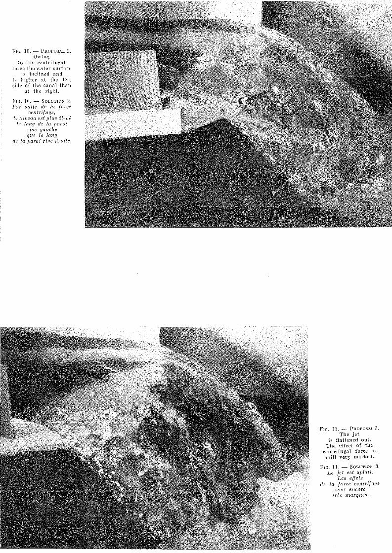
FIG. 10. - PI\OI'OSAL 2.Owing
ta the centrifugaIforcc the watcr surface
is inclined andis h igh~r a t the Icftsidc of the canal than
at the right.
FIG. 10. - SOLUTION 2.Par suite de la force
centrifuge,le niveau est plus élevé
le long de la paroil'ive gaucheque le long
de la paroi l'ive droite.
FIG. 11. - PROPOSAI. 3.The jet
is flattened out.The effect of the
centrifugaI force isstill very marked.
FIG. 11. - SOLUTION 3.Le jet est aplati.
Les effetsde la force centriful1 c
son t encoretrès marqués.
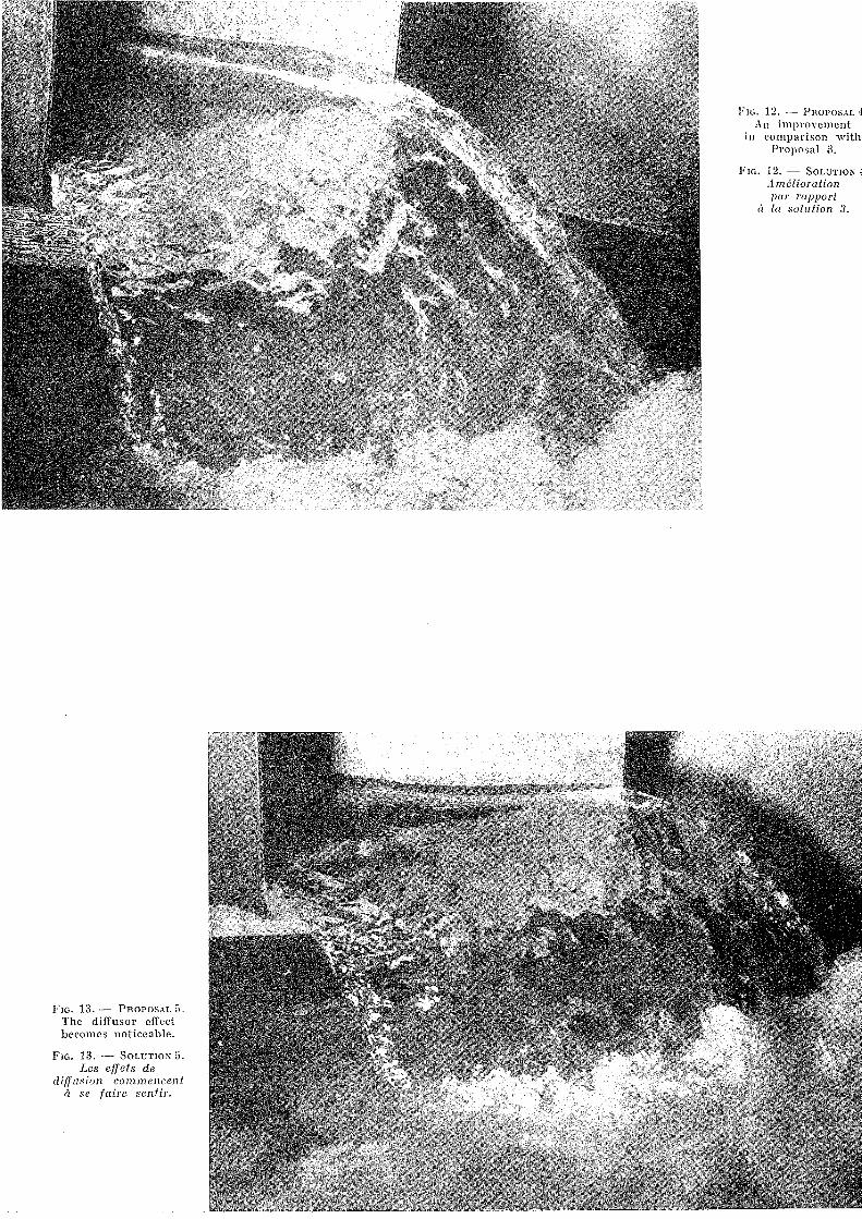
1'10. 12. -- PnoPosAL 4An ill1provement
in cOll1parison withProposaI 3.
FIG. 12. - SOLUTION 4;lméliorationpar rapport
ci la sollltion 3.
FIG. 13. - PnoPosAL 5.The diffusor effecthecomes noticeable.
FIG. 13. - SOLUTION 5.Les effets de
diffusion commencentà se faire sentir.
DÉCE~!llHE 1953 LA HOUILLE BLANCHE 879
was decided to test a completely new shape ofthe flood-outlet canals. Instead of narrowingthe downstream end to get concentrated waterjets, the canals were successively widened andthe downstream ends ,vere given a fan-shapeddesign. This resulted in the water being distributed along a considerable stretch before beingdischarged bad. into the river, so that largequantities of air eould be entrained. These factors wou Id help to reduce the risk of crosion ofthe river bed.
Tests were carried out with live models ofthis type, ProposaIs 2 to 6, built of masonite tothe scale of 1 : 180, and a similar model wasalso made of ProposaI 1, ail models representingthe left canal only, Fig. 3.
In ProposaI 2 the downstream edge, nearlypm'allel to the river, was made almost twice aslong as that in ProposaI l, and in ProposaI il
abouL two and a half Limes as long. Thus thedownstream end of the canal acquired the shapeof a diffusor, giving the jet a wide dispersion.
ProposaI 4 difl'ered l'rom ProposaI il mainlyin that the canal was narrowed in the middle.This further emphasized the dilTusor shape, andthe dispersion of the jet became more pronounced.
In Proposai 5 the left side of the canal \Vasstraigh tened out l'rom the do\Vnstream edgealong a eonsiderabl(~ distance upstream (about11il of Lhe entire length of the canal). Thisresulted in the advantages of Proposai 4 beingfurther inereased.
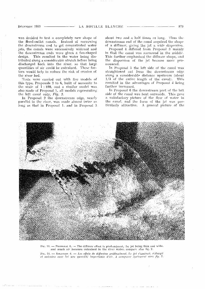
ln ProposaI 6 the downstream part of the lensicle of the canal was bent outwards. This gavea satisfactory picture of the How of water inthe canal, and the fonn of the jet \Vas particularly attractive. A generai picture of the
FIG. 14. - Pno!'osAL li. .- The diffusor effect is predominant, the jet being thin and \Vide,and mueh air becomes 'cntraincd in thc river \Vatel', comparE: also fig. 2.
FIG. 14. -- SOLUTlON G. - Les effets de diffzlsion prédominent. Le jet s'amincit, s'élargit('/ entraine auec lui une quantité importante d'air. il computer é(Ju/ement uuec fl(J. 2.
880 LA HOUILLE BLANCHE DÉCEMBHE 1953
How in a number of eanal models is shown in thephotographs in Figs. 4 to 8, ,vhile the fonn ofthe jet at the downstream section of the canalin the various models is shovvn in Figs. 9 to 14.
After the completion of the tests on the supplementary models, ProposaI 6 was incorporatedin the main model to the scale of 1 : 60, Fig. 2.
It is difficult to study in a model the extentof the erosion of the rock at the place wherethe jet hits the river, but the erosive efIect willobviously be greater when the jet is concentraledthan when it is spread out. A considerablygreater amount of air will he entrained whcnthe jet is spread out over a wider area, andt11is will also tend to reduce erosion. As will
be seen l'rom Fig. 2, it was fOlmd in the modelthat a considerable quantity of air was entrained in the river water and that the surgesin the river were insignificant.
The force with which the water struck againstthe banks was fOlmd to he considerably lessin ProposaI (j than in ProposaI ].
An attempt to reduce the width of the canalslill further than in the supplementary modelof ProposaI (j gave negalive results. The crossseetion then became too narrow and gave rise10 a hydraulie jump.
In view of the ahove faets, ProposaI (j wasconsidered to give the hesl means of disehargingwaler l'rom the flood-outlet canals into the river.
DÉCDIBHE J 05:3 LA HOUILLE BLANCHE 8~1
r
E\/acuateu rs de crue en éventa ils
J)IHECTECH Di.; J..:\BOHATOIHE n'HynHAULIQlJE
}7: COLE l~OYALE POLYTEC]-!NIQUE SCPI~HIEcnE, STOCl\HOL:\1
English text, page 873.
Eillde sllr moddes r,:dllils (lin modèle d'ensemble 011 1 1(jO, li modMes porliels IllI 1/180) dl'dl'lu: conOlU' élJlIClloll'lIrs de l'l'Ile conlollrnolll,chaclln SIlr llne ripe, un barrage en cnrochemenls, el débouchanl, à l'ovol, 12 nI alI-dessuscles plllS hallies eOllX de la rivière. Chaque
cllnlll esl pr':llll llO/Ir posser 5500 m;l/s, Mise (Ill
/Joinl des dispositions permettanl de rédllire IllI
maximll1l/ l'IIyillltion el les dégrlldllliOl/s résulIlInles dll Iii 011 des OlWl'lIyes pllr {es nllppesiléversantes.
Dans de nombreu5es installations hydro-électriques les crues sont évacuées par un canal établiSUl' l'une des rives de la rivière. Ceci est tout particulièrement le cas lorsqu'il s'agit de harrages enterre ou en enrochement, dans lesq:uels l'eau nepeut pas déverser par-dessus le barrage lui-même.Il convient de prendre des précautions afin créviter une érosion grave du lit, surtout si le canalévacuateur débouche à une ccrta-ine hauteur audessus du niveau de la j'ivière : sa (lisposition doitviser à réduire le plus possible l'agitation, de fa(;on à éviter d'endommager les rives de la rivièreou les ouvrages voisins.·
Dans cc qui suit, nous décrivons hrièvement desessais sur modèle réduit destinés à mettre au pointles dispositions d'un évacuateur de crue, fonction·nant dans les conditions ci-dessus. Ces essais ontl~,é efl'ectul's au Laboratoire d'Hydraulique de j'EcoleHoyale Polytechnique Supérieure de Stockholm, enSuède (').
LES OUVHAGES
Les ouvl'ag'es, dont il est question ICI, comporteront une centrale souterraine creus('e ct aménug~e dans le rocher sur la rive droite de la rivièr(\et un barrage en enrochement. A chacune de sesextrémités Je harrage sera contourné par un canalévacuateur de crue fermé par deux vannes. Pendant les travaux les eaux pa,sseront pal' deux galeries de dérivation, une dans chaque rive, CI'eUsées dans le roeher en dessous du canal évac'1<\teur, l'emplacement du barrage étant protégé pardeux batardeaux étahlis en travers de la rivière.l'un à l'amont et l'autre à l'aval. La cr(~te du har-
(') Les Ingénieurs Conscils de cc projet sont Vattenbyggnadsbyran (VB13), Stockholm.
rage en enroehement se trouvera environ 70 m audessus du fond rocbeux de la rivière. Le débitmaxilllulll devant emprunter chacun des eanaux estestimé à 5.500 m:J/s; à leur extrémité aval ces canauxsc trouveront à 12 m au-d'essus du niveau des plushautes eaux de la rivière. Le rocher en plaee dansle lit de la rivière se trouve ~nviron 28 mau-dessousdu niveau des plus hautes eaux. La figure 1 (**)donne le plan général des installations, et la figure 2est une photographie du modèle d'ensemble vuvers l'amont. La figure 1 donne la disposition deseanaux telle qu'elle avait été prévue avant les essais(projet 1) tandis que, sur la fig'ure 2, ces canauxont la forme mise au point d'après les essais (projet G).
CONSTHUCTION DU MODÈLE
Le modèle principal a été réalisé à l'échelle dul/GO' tandis que G modèles complémentaires auJ /180c étaient destinés à faire uné étude séparée descanaux. Le modèle principal fut d'abord réaliséavec les canaux tels qu'ils avaient été prévus auprojet 1, puis, par la suite, le modèle fut retouchéet mis au point suivant la disposition du modèle G.
Le modelé du modèle principal fut réalisé en sebasant sur la carte en courbe' de niveau etu site àpartir de gabarits en bois traité (Masonite) disposés de 50 en 50 cm sur la plateforme supportantle modèle. L'espace compris entre ces gabarits futrempli de sahle, lequel ayant été arrosé d'eau ettassé servit de support à une couche ete 3 cm d'unenduit très riche en ciment constituant la surfacedu modèle.
La prise d'eau alimentant la Centrale et les par-
(* *) Pour les figures, se reporter au texte anglais,p. 873.
882 LA HOUILLE BLANCHE DÉCEMBRE 1953
tics en béton des évacuateurs de crue furent construites en bois et peintes. Le barrage en enrochement fut réalisé avec des pierres concassées j,usqu'au calibre de 10 mm; il comportait lin noyauétanche fait de hrique pilée et de ciment.
Les G modèles complémentaires furent réalisésen bois traité (l\lasonite).
ESSAIS sun LES DIFFÉRE:\TS MO[)ÙLES
Chacun des (j projets furent mis au point avecl'intention d'obtenir, au moindre coût, les dispositions les mieux il même d'assurer le déversementdans la rivière, en réduisant au minimum l'érosiondu lit ct l'agitation.
Dans le projet 1, la largeur des canaux évacuateurs allait en diminuant gradueHement vers l'aval,la nappe déversante étant approximativement aussihaute que large. Le radier de chacun des canaux,il l'extrél11ih~ aval, était disposé de telle sorte quela nappe, en abandonnant l'ouvrage, se retournait,provoquant ainsi un entraînement d'air. Les essaissur modèle montrèrent, cependant, que lorsqu'elleatteignait la rivière, la nappe, encore très ramassée,était il même de provoquer une érosion importante. Le jet étant dirigé obliquement par rapportil la direction de la rivière, l'cau frappait violemment la rive opposée, surtout lorsqu'un seul descanaux fonctionnait; il en résultait dans la rivièreune très forte agitation difficilement acceptable.
En vue d'éviter ces inconvénients, il fut décidéd'essayer pour les canaux évacua;leurs une formeenlièrement nouveJle. Au lieu de rétrécir l'extrémité aval pour réaliser des jets d'eau concentrés,les canaux furent peu il peu élargis, et leur extrémité aval réalisée en forme d'éventail. Avant de sedéverser (lans la rivière l'eau se trouvait ainsi étalée en une large nappe, si bien qu'elle pouvait entrainer une gran(k quantité d'air. Ces facteurs permettaient d'espérer une réduction des risques d'érosion du lit.
Les essais d'une telie drisposition furent conduitssur 5 modèles (projets 2 il G) construits en « Masonite» il l'échelle du 1/180"; un modèle similairefut fait également du projet 1, tous ces modèlesreprésentant seulement le canal rive gauche (fig. 3).
Dans le projet 2, le seuil aval, il peu près parallèle il la rivière, était environ deux fois plus large
que dans le projet 1; dans le projet 3 il était deuxfois et demi plus lar,ge. Ainsi l'extrémité aval ducanal prenait la forme d'un diffuseur assurant aujet une très large dispersion.
Le projet cl différait du projet :3 I~rincipalement
pal' un rétrécissement du canal en son milieu. Ilen résultait encore llne accentuation de la formedu diffuseur et la dispersion du jet se faisait plusprononcée.
Dans le projet 5 la paroi rive gauche du canalfut rendue rectiligne, depuis l'extrémité aval jusqu'assez loin en amont (environ 1/3 de la longueurtotale du canal); ccci permit encore d'accentuer lesavantages du projet 4.
Dal1Js le projet n" G, la partie aval de la paroirive gauche du canal fut infléchie.: vers l'extérieur.L'écoulement dans le canal présenta alon, un aspectsatisfaisant, et la forme du jet était particulièrement séduisante. Les figures 4 à 8 montrent l'allure générale dL' l'écoulement sur de nombreuxmodèles de canaux, tandis que les figures 9 il 14penneltent de sc rendre compte de la forme dujet dans la section aval du canal sur les diversmodèles.
Une fois terminés les essais sur les modèlescomplémentaires, le projet G fut reporté sur le modèle principal il l'échelle du l/GO" (fig. 2).
11 est difficile, sur un modèle, de se rendrecompte exactement de l'érosion du l'ocher en placelorsque le jet frappe la rivière; mais il est évidentque la capacité d'érosion est plus ,grand:e lorsquele jet est concentré que lorsqu'il est dispersé. Lejet entraine d'autant plus d'air qu'il est plus largement étalé, cc qui tend aussi il réduire l'érosion.Comme on peut le voir sur la figure 2, le modèlemontra qu'une grande quantité d'air était entrainéedans l'eau de la rivière dont l'agitation, était insignifiante. La violence avec laquelle l'cau frappaitles rives s'avéra bien moindre sur le projet G quesur le projet 1.
Une tentative de réduire la largellr du canal encore davantage qlle dans le modèle complémentairedu projet fi ne donna pas de résultat. La sectiondevient alors trop étroite et donne naissance il unressaut.
Compte tenu des observations ci-dessus, le projet G fut considéré comme correspondant aux meilleures conditions de restitution de l'cau depuis lecanal évacuateur jusqu'à la rivière.