Embed Size (px)
Citation preview

of 43
Fabrication Manual
Project: C.H. Robinson Midwest HQChicago, LEED Gold
Architects: Skidmore, Owings, & Merrill LLP
Fabricator: Sobotec Ltd.
ALUCOBONDUSA.COM / 800.626.3365
This fabrication manual has been developed to assist fabricators to work with 4mm ALUCOBOND® PLUS material in the most efficient and effective manner. The recommendations in this manual are the result of many years of combined experience by fabricators in North America.

December 2019ALUCOBOND® is a registered trademark of 3A Composites USA Inc. © 2020 3A Composites USA. All Rights Reserved.
FABRICATION MANUAL
ALUCOBONDUSA.COM / 800.626.3365
of 43
TABLE OF CONTENTS
Sawing................................................................................................................................ Blade Recommendations.................................................................................................... Shearing............................................................................................................................. Jointing or Filing of Edges..................................................................................................Routing: For Bending..........................................................................................................Small Radius Bending (By Routing).....................................................................................Curving...............................................................................................................................Drilling................................................................................................................................Punching.............................................................................................................................
General Advice on Joining Elements................................................................................... Threaded Fasteners............................................................................................................Rivets..................................................................................................................................Concealed Fastening..........................................................................................................Adhesive Guidelines...........................................................................................................
Details................................................................................................................................
Painting...............................................................................................................................Screen Printing...................................................................................................................Panel Repair........................................................................................................................
Deflection...........................................................................................................................Windload Data....................................................................................................................Thermal Expansion..............................................................................................................Technical Data....................................................................................................................
Storage...............................................................................................................................Fabricating Tables...............................................................................................................Masking..............................................................................................................................
Adhesives............................................................................................................................Blades and Bits....................................................................................................................Extrusions............................................................................................................................Fasteners.............................................................................................................................Fabricating Tables...............................................................................................................Machinery...........................................................................................................................Masking...............................................................................................................................Paints..................................................................................................................................Sealants..............................................................................................................................Screen Print Inks.................................................................................................................Tapes...................................................................................................................................
A. B. C. D. E. F.G. H. I.
A. B. C. D.E.
A.
A.B.C.
A.B.C. D.
A.B.C.
A.B.C.D.E.F.G.H.I.J.K.
Section I: Fabricating
Section II: Joining
Section III: Concepts
Section IV: Off Line Finishing
Section V: Engineering
Section VI: Processing
Section VII: Sources
Introduction.................................................................................................................................... 2
3344559111212
131313151619
3434343637
39393940
414141414142424242434343
2020
29293233
1

December 2019ALUCOBOND® is a registered trademark of 3A Composites USA Inc. © 2020 3A Composites USA. All Rights Reserved.
FABRICATION MANUAL
ALUCOBONDUSA.COM / 800.626.3365
of 43
This fabrication manual has been developed to assist fabricators to work with ALUCOBOND® PLUS material in the most efficient and effective manner. The tips and suggestions contained in this manual are the result of many years of combined experience by fabricators in both North America and Europe.
The recommended suggestions and product data are based on information which is, in our opinion, relia-ble. However, since skill, judgment, and quality of equipment and tools are involved, and since conditions and methods of using ALUCOBOND PLUS material are beyond our control, the suggestions contained are provided without guarantee. We recommend that prospective users determine the suitability of both the material and suggestions before adopting them on a commercial scale. 3A COMPOSITES USA INC. DOES NOT MAKE ANY WARRANTIES, EXPRESS OR IMPLIED, INCLUDING MERCHANTABILITY AND FITNESS FOR PURPOSE, WITH RESPECT TO ANY SAID SUGGESTIONS AND PRODUCT DATA. In no event shall 3A Composites USA Inc. have any liability in any way related to or arising out of said suggestions and product data for direct, special, consequential or any other damages of any kind regardless whether such liability is based on breach of contract, negligence or other tort, or breach of any warranty, express or implied.
Also, normal safety and health precautions practiced in any fabricating environment should be used when fabricating ALUCOBOND PLUS material. Goggles or other face protection, as well as hearing protection should always be worn.
SDS for ALUCOBOND PLUS material are available through our Customer Service Department.
This fabrication manual is written to address the fabrication of 4mm ALUCOBOND PLUS material. Although DIBOND material (2mm, 3mm, 4mm) is a similar composite, it is not covered by this manual. Questions regarding DIBOND material are answered in the DIBOND material Processing Manual.
INTRODUCTION
2

December 2019ALUCOBOND® is a registered trademark of 3A Composites USA Inc. © 2020 3A Composites USA. All Rights Reserved.
FABRICATION MANUAL
ALUCOBONDUSA.COM / 800.626.3365
of 43
ALUCOBOND PLUS material is manufactured with any one of several high quality finishes. It is best to movethe saw blade rather than the material in most operations. Saw cutting can be accomplished with the follow-ing cutting equipment:
A. Sawing (For Sizing Panels)
Table saws are not recommended for cutting sheets larger than 4’ x 4’ in size.
Panel saws provide an effective method of cutting. These saws, whether standard equipment or custommade, perform well and have the added advantage of space savings. If a panel saw is to be used as produc-tion equipment, an industrial model should be purchased in order to obtain adequate cutting tolerances andincrease the longevity of the equipment.
In high production operations, equipment that is capable of performing more than one operation with a singlepass through the machinery may be used. This equipment can make multiple saw cuts (sizing the panel) andV-Grooves (rout) at the same time.
Cutting ALUCOBOND PLUS material with portable circular saws is another effective method. As mentioned,this equipment should also be production/industrial type equipment.
Reciprocating saws work well for cutouts. Care should be aken with portable saws and reciprocating sawsto prevent damage to the ALUCOBOND PLUS material surface. More than one sheet can be cut at a timeby stacking panels. If center cutting (i.e., letter cutouts) is required, a foam pad may be placed under thematerial with the reciprocating blade cutting into the foam. The sheets may be clamped or secured withdouble-faced tape for the cutting operation. When clamping between jaws, protect the panel surface againstdamage.
Considerate care should be taken in the layout and handling of ALUCOBOND PLUS material. Refer to Section VI of this manual for information on care and handling.
The use of coolants or lubricants is not required when sawing.
1. TABLE SAWS
2. PANEL SAWS
3. MULTIPLE OPERATION RIP/V-GROOVING SAWS
4. PORTABLE SAWS
5. RECIPROCATING SAWS
Section I: FABRICATING
3

December 2019ALUCOBOND® is a registered trademark of 3A Composites USA Inc. © 2020 3A Composites USA. All Rights Reserved.
FABRICATION MANUAL
ALUCOBONDUSA.COM / 800.626.3365
of 43
Consult Table I for recommended blades and cutting speeds for various types of saws.
ALUCOBOND PLUS material can be easily sheared. However, a slight roll-down of the aluminum cover sheetmay occur on the impact side (reference Figure 1). This roll-down area is often referred to as the “edge zone.”In this area, the polythylene core is compressed and can lead to increased stress between the core and thealuminum cover sheet. Due to this additional stress, shearing should be avoided when the edge of the panel esexposed to the environment.
When shearing ALUCOBOND PLUS material, light markings on the material may be caused by the hold down pads. In order to avoid these markings, the hold down on the shear should be fitted with a shock-absorbing rubber pad which will help to prevent damage to the ALUCOBOND PLUS material.
B. Blade Recommendations
TABLE 1
Figure 1 - Shearing
C. Shearing
0.4mm (Approx.)
Rollover of cover sheet when sheared
Section I: FABRICATING cont’d.
WORKING METHOD
CUTTING MATERIAL
BLADE OR BAND GEOMETRY
TOOTH GEOMETRY
CUTTING SPEED (MAX.)
CUTTING FEED (MAX.)
Circular Saws
Carbide tipped or high-speed steel(For anodized finish, use Carbide tipped only.)
8” x 14” blades with max-imum number of carbide teeth available, designed for cutting nonferrous material. The blade should be ground thinner from the rim towards the center to prevent pinching.
Angle or circular tooth, alternate beveled, triple ground. Tooth gap wall rounded. Chip angle: 5o to 15o. Clearance angle: 10o to 30o. Tooth spacing: 3/16” to 1” (4mm to 25mm), fine spacing preferable.
5,500 RPM 16”/second
Bandsaws Tempered spring strip steel
Thickness: .03” to .047” (0.8mm to 1.2mm). Width: 9/16” to 1” (15mm to 25mm). Use racket or straight set.
Skip teeth, designed for nonferrous and ferrous materials (light metals & plastics). Tooth spacing: minimum ten teeth per inch.
10,000’/min. 10”/second
Reciprocating saws High-speed steel
Thickness: .03” to .047” (0.8mm to 1.2mm). Width: 3/16” to 9/16” (15mm to 15mm). Use racket or straight set.
Hook or circular tooth with alternate angles, set or waved. Tooth spacing: .010” to .250” (2mm to 6mm). (Plywood blade).
4”/second
4

December 2019ALUCOBOND® is a registered trademark of 3A Composites USA Inc. © 2020 3A Composites USA. All Rights Reserved.
FABRICATION MANUAL
ALUCOBONDUSA.COM / 800.626.3365
of 43
Floor model woodworking jointers are effective for edge finishing.
For finishing work, after contour cutting with a reciprocating saw (ordinary cutting files work best), the file profile should be from slightly to fulling rounded. The proper filing direction is length-wise along the edge.
Unlike sheet metals which require the use of a large break press for folding fabrication, ALUCOBOND PLUS material can be accurately folded by hand after a simple routing operation is done on the back skin. Anytime a blueprint shows a fold line, this routing operation is done at the location of the bend. This fabrication method is unique to composite panel fabrication and is referred to as Rout & Return. Floor model woodworking jointers are effective for edge finishing.
ALUCOBOND PLUS material may be routed using one of the two following methods: (Either method should use high-quality industrial equipment.)
One procedure for routing ALUCOBOND PLUS material is to use an industrial or commercial grade, hand-op-erated router. For production operations this method is relatively slow. The recommended feed rate is 6’ to 10’ per minute using carbide tipped cutters.
Special custom cutters for ALUCOBOND PLUS material are available (reference Section VII). These cutters have been specifically developed for ALUCOBOND PLUS material and will produce the required configuration for proper rout tolerances. Commercially available 90o wood working routing cutters, available from your local hardware store, may be modified to provide approximately the same function as the custom cutters, provided the tip is ground to a (or flattened) 1/16” minimum at the point (reference Figure 2).
Keep router bit sharp to reduce heat build-up and the need to rerout fused core material.
D. Jointing or Filing of Edges
E. Routing: For Bending
1. ROUTER
Figure 2 - Router Bits
CustomCommercially available wood
working router bit
95o
to
105o
90o
1/16” MIN.
Section I: FABRICATING cont’d.
5

December 2019ALUCOBOND® is a registered trademark of 3A Composites USA Inc. © 2020 3A Composites USA. All Rights Reserved.
FABRICATION MANUAL
ALUCOBONDUSA.COM / 800.626.3365
of 43
For fabrication of a large number of sheets that require routing, a portable circular saw fitted with a special blade is advisable (reference Figure 3). This blade is often referred to as a “V” Routing Blade. These blades, used with a quality industrial saw, you will produce the required tolerances at a much faster rate than hand rout-ers (reference Section VII). Many fabricators use a worm gear-driven industrial-quality saw, with a larger plastic base plate added for stability.
The depth of the “V” rout is critical. As a rule of thumb, the visual appearance of the rout line should be consist-ent along the entire length of the rout (reference Figure 4). Extreme care should be taken not to touch the exterior aluminum skin with the router bit or saw blade. Slight variations can occur due to thickness changes in the ALUCO-BOND PLUS material sheet; constant depth of the rout ensures a good smooth line when the edge is folded.
The same guidelines should be used when routing with a “V” Routing Blade on a portable circular saw or with a portable router. Figure 4 indicates the finished rout required to develop a quality bend. Leave skin plus 1/64” of PLUS core.
2. CIRCULAR SAW (CUSTOM BLADE)
Figure 3 - Routing Saw Blade (“V” Routing blade)
AA
1/16” minimum
Section A-A
90o
Figure 4 - Routing
90o to 105
Interior (Back Side)
Exterior (Face Side)
1/64”
Section I: FABRICATING cont’d.
6

December 2019ALUCOBOND® is a registered trademark of 3A Composites USA Inc. © 2020 3A Composites USA. All Rights Reserved.
FABRICATION MANUAL
ALUCOBONDUSA.COM / 800.626.3365
of 43
By routing only one side, ALUCOBOND PLUS material can be bent either upward or downward to create both an inside or outside corner as illustrated in Figure 5.
NOTE: The material is most easily bent when the rout is made at least one inch or more from the edge of the panel.
Figure 5 - “V” Routing
Rout the same side for either bend.
An ALUCOBOND PLUS material “pan” is easily fabricated by routing all four sides, notching the corners (shown in Figure 7 and Figure 8), and folding or returning each of the routed sides (reference Figure 6). This type of fabrication is commonly referred to as “Rout & Return.”
Note that as a result of the slight radius produced when bending, your finished panel dimension will be 1/32” to 1/16” larger when folded. This is determined by the profile of the cutter used to make the rout. Trial cuts should be made prior to production to determine any necessary adjustments in layout dimensions (feference Figure 6).
On the following page, two different methods of fabrication are illustrated showing how corners may be handled on the folded or “returned” leg of the “pan.”
Figure 6 - Routing
Panel of Pan Dimension
Panel or Pan Dimension + 1/16”
Section I: FABRICATING cont’d.
7

December 2019ALUCOBOND® is a registered trademark of 3A Composites USA Inc. © 2020 3A Composites USA. All Rights Reserved.
FABRICATION MANUAL
ALUCOBONDUSA.COM / 800.626.3365
of 43
Figure 7 - Square Corner Cutouts
Figure 8 - Envelope Corner Cutous
INSIDE
INSIDE
Section I: FABRICATING cont’d.
8

December 2019ALUCOBOND® is a registered trademark of 3A Composites USA Inc. © 2020 3A Composites USA. All Rights Reserved.
FABRICATION MANUAL
ALUCOBONDUSA.COM / 800.626.3365
of 43
A very small radius can be achieved by “V” routing and folding (reference Figure 9).
By changing the shape of the cutter used, a larger radius can be achieved. A flatter, wider cut will result in a smoother bend (reference Figure 10). Care must be taken when sliding the router across the ALUCOBOND PLUS material to avoid surface scratches. Care must also be taken to avoid cracking the paint of the surface. A minimum of a 1-T radius is required for the ALUCOBOND metal and paint.
F. Small Radius Bending (by routing)
Figure 9 - “V” Routing
Figure 10 - Flat Routing
Very small radius
Larger radius
Section I: FABRICATING cont’d.
9

December 2019ALUCOBOND® is a registered trademark of 3A Composites USA Inc. © 2020 3A Composites USA. All Rights Reserved.
FABRICATION MANUAL
ALUCOBONDUSA.COM / 800.626.3365
of 43
Figure 11 - Routing Concepts
Rout at each fold line
Bend along fold line
Notch as in normal sheet mteal work
Section I: FABRICATING cont’d.
10

December 2019ALUCOBOND® is a registered trademark of 3A Composites USA Inc. © 2020 3A Composites USA. All Rights Reserved.
FABRICATION MANUAL
ALUCOBONDUSA.COM / 800.626.3365
of 43
The minimum bending radius for 4mm ALUCOBOND PLUS material without routing the back skin is 4” (101mm).
ALUCOBOND PLUS material can be cold formed in a pyramid roller or a press brake. The process is similar to the forming of aluminum; however, due to the sensitive surface, care should be taken to ensure rollers are clean, smooth, and free of defects to avoid damage to the surface finish.
As an extra precaution, a film should be used between the panel and the rollers to further protect the panel surface. Do not pinch the ALUCOBOND PLUS material between the rollers. Roll the panel 3o to 5o tighter to allow for a small amount of springback that will occur. Once the sheet is curved; however, it will remain curved (reference Figure 12).
1. Make sure rollers are clean 2. Use protective material between rollers and ALUCOBOND PLUS material (top and bottom)3. Adjust rollers for thickness (4mm)4. Allow 2” to 4” scrap at each end for typical pyramid rolling.
G. Curving
Figure 12 - Pyramid Roller
1. PYRAMID ROLLER
2” to 4” scrap
Section I: FABRICATING cont’d.
11

December 2019ALUCOBOND® is a registered trademark of 3A Composites USA Inc. © 2020 3A Composites USA. All Rights Reserved.
FABRICATION MANUAL
ALUCOBONDUSA.COM / 800.626.3365
of 43
As an extra precaution, a film should be used between the panel and the rollers to further protect the panel surface. Do not pinch the ALUCOBOND PLUS material between the rollers. Roll the panel 3o to 5o tighter to allow for a small amount of springback that will occur. Once the sheet is curved; however, it will remain curved (reference Figure 13).
2. PRESS BRAKE
Protective Film
Bending Die (Snaker)
T
ALUCOBOND PLUS material can be worked with twist drills usually used for aluminum and plastics, and on drilling machines customarily used for metals.
Working Specifications:Drill Bit: Twist drill, high-speed steel Tip Angle: 100o to 140o, or counterbore grind with centering tipCutting Speed: 164 RPM to 984 RPM
Quick removal of chips can be achieved by a process of high revolution, slow feed and occasional lifting of the drill bit.
The punching of flat-formed parts from ALUCOBOND PLUS material is performed the same way as the solid aluminum sheet, using evenly ground tools and the narrowest possible cutting gap. Be sure to punch through the ALUCOBOND PLUS material to completely serrate the core material. As with shearing, a slight roll down may occur. Refer to the section on shearing for additional information.
H. Drilling
I. Punching
Figure 13 - Press Brake
Section I: FABRICATING cont’d.
12

December 2019ALUCOBOND® is a registered trademark of 3A Composites USA Inc. © 2020 3A Composites USA. All Rights Reserved.
FABRICATION MANUAL
ALUCOBONDUSA.COM / 800.626.3365
of 43
Section II: JOINING
Use the following guidelines when other elements come in direct contact with the surface of ALUCOBOND PLUS material: 1. Acceptable joining element materials: Aluminum Stainless Steel Plated or coated steel with cadmium, zinc, or aluminum 2. Unacceptable joining element materials: Copper Brass Bronze Iron Raw SteelUnacceptable materials cause corrosion of joining surfaces due to electrolysis of dissimilar materials. There-fore, use “heavy” or “red” metals only with an electrically insulating intermediate layer.
When joining elements are to be anodized, assemble the materials after the anodizing process.
Proper consideration should be given to the thermal expansion characteristics of ALUCOBOND PLUS material when using any of the joining techniques. Refer to Section V, Subsection C for the method of determining thermal expansion of ALUCOBOND PLUS material.
The easiest method of joining sheets of ALUCOBOND PLUS material together or to an extrusion profile erection system is with machine screws or bolts (reference Figure 15 below). This method allows the panel to be removed. Use the largest possible flat washer to minimize surface pressure and eliminate possible compression due to cold flow of the core material. Arrange attachment screws at least 2.5 x the diameter of the fastener from the edge of the sheet, as shown in Figure 16 on the following page.
It is not recommended to torque fasteners due to the cold flow of the core material. Two complete turns of the nut past finger tight is common practice (reference Figure 17 on the following page.)
A. General Advice on Joining Elements
B. Threaded Fasteners
Minimum 2.5 to 3 times diameter
Diameter
Figure 15
13

December 2019ALUCOBOND® is a registered trademark of 3A Composites USA Inc. © 2020 3A Composites USA. All Rights Reserved.
FABRICATION MANUAL
ALUCOBONDUSA.COM / 800.626.3365
of 43
Section II: JOINING cont’d.
Figure 16
Figure 17
2.5 x diameterminimum
Excessive torque (not recommended)
Figure 18
Preferred
Traditional(not recommended)
To countersink into ALUCOBOND PLUS material without prior preparation, tighten the nut and washer onto the bolt and draw the head of the fastener into the cover sheet. Countersink washers can also be used. Either method is preferable in lieu of traditional countersinking as shown in Figure 18.
Preferred
14

December 2019ALUCOBOND® is a registered trademark of 3A Composites USA Inc. © 2020 3A Composites USA. All Rights Reserved.
FABRICATION MANUAL
ALUCOBONDUSA.COM / 800.626.3365
of 43
Panels of ALUCOBOND PLUS material can be fastened together or joined to aluminum extrusion profiles or other sheet metals with rivets common to aluminum construction. Blind rivets provide the advantages of labor savings, one-sided working of the material, and the reduced potential of surface damage. Semi-tubu-lar, solid and other types of rivets can also be effective on a production basis.
Place the closing or set-head on the side of the aluminum extrusion profile or sheet metal. When conditions do not permit this or when two pieces of ALUCOBOND PLUS material are to be joined together, use rivets with special wide closing heads as shown in Figure 19 or with tightly fitting washers.
When blind rivets are subjected to tensile strength tests, the head tends to “unbutton” from the ALUCOBOND PLUS material, or pull through the hole. Since this would cause localized tearing of the ALUCOBOND PLUS material, use the largest possible rivet head for connections that will experience loading.
Aluminum alloys such as 5032 and 5154 are suitable rivet material. Due to stress corrosion, alloy 5056 should not be used if the temperature of the manufactured part is expected to rise over 140o F (60o C).
Rivet connections are well suited for parts that may be subjected to concussion or vibration. Colored plastic concealment caps are available for various types of blind and tubular rivets. Consult the rivet manufacturer for details. Follow the directions and determine suitability by pre-testing.
C. Rivets
Figure 19
Section II: JOINING cont’d.
15

December 2019ALUCOBOND® is a registered trademark of 3A Composites USA Inc. © 2020 3A Composites USA. All Rights Reserved.
FABRICATION MANUAL
ALUCOBONDUSA.COM / 800.626.3365
of 43
Most adhesives and sealing compounds do not adhere to the core material; therefore, bond to the aluminum skin of the ALUCOBOND PLUS material only (reference Figure 21).
To achieve reliable bonding, it is imperative to follow the adhesive manufacturer’s instructions.
For interior design purposes, high strength contact adhesives that do not require lengthy setting times can be used to achieve particularly high shear strengths.
Where moderate cure times are acceptable, construction adhesives should be considered.
When longer cure times are not objectionable, silicones can be used successfully. However, it may be necessary to hold the components with foam tape while the silicone sets.
When using an adhesive to hold dissimilar materials, select one that will handle thermal movement without shearing. Use a low modulus sealant where greater amounts of movement are expected (i.e.., plastics to aluminum), and high modulus sealants if minimum movement is expected (i.e., bonding aluminum to aluminum).
1. ADHESIVE BONDING
Figure 21
Cutout
Silicone1/8” minimum
PlasticFoam Tape
One of the architectural and display features in great demand is the ability to attach ALUCOBOND PLUS material to a substrate without having exposed fasteners. Although there are some techniques to accomplish this using conventional fasteners, the vast majority of this type of connection is done using adhesives. To develop some general guidelines, 3A Composites USA Inc. has reviewed some well-known adhesives and can present the following information.
The General Guidelines on page 19 have been established based on the research done into the use of adhesives on ALUCOBOND PLUS material.
Concealed fasteners may be used when a smooth, exposed surface is required, as in exterior building cladding, interior surfaces, signs, exhibits, store fixtures and furniture. Several fastening options are available, including adhesives and mechanical attachments. All of these methods have medium to low load transmitting capacity compared to conventional fasteners.
D. Concealed Fastening
Section II: JOINING cont’d.
16

December 2019ALUCOBOND® is a registered trademark of 3A Composites USA Inc. © 2020 3A Composites USA. All Rights Reserved.
FABRICATION MANUAL
ALUCOBONDUSA.COM / 800.626.3365
of 43
Section II: JOINING cont’d.
17
Figure 22 - Stud Welding
Another approach for attaching to ALUCOBOND PLUS material has been developed which is very fast and easy. This attachment method utilizes a special stud that has no threads, together with a push nut.
This non-threaded stud must be manufactured of the most compatible alloys to ensure the maximum weldability possible to the panel. The proper stud can be easily fastened or welded using a standard capacitor discharge stud welder. The use of a non-threaded stud eliminates the problems of finding the lead threads, paint in the threads, or of most importance, the possibility of over torquing the retaining nut which could shear the weld (reference Figure 22).
The push nut has a built-in washer and locking function. Therefore, the use of a washer, lock washer and nut are not needed. Installing the push nut is a simple thrust with a nut driver. Performing stud welds on a test panel to observe the impact on the opposite surface is recommended as read-through can be a problem.
To remove, the self-threaded push nut is unscrewed. Oversized holes are drilled in the material to be attached at the stud locations prior to installation. Paint should be removed at each stud location by mild abrasion or with the use of paint removers prior to welding. Care should be used to select the proper settings depending on the stud welding gun and the thickness of ALUCOBOND PLUS material.
2. “STUD WELDING” ON ALUCOBOND PLUS MATERIAL
For concealed attachment, double-faced high strength foam tapes are effective. The purpose for these various tapes are: 1) to hold material under limited load applications, 2) to hold material in line while silicone sets, and 3) for sealing (reference Table 2 on page 19).
3. TAPES

December 2019ALUCOBOND® is a registered trademark of 3A Composites USA Inc. © 2020 3A Composites USA. All Rights Reserved.
FABRICATION MANUAL
ALUCOBONDUSA.COM / 800.626.3365
of 43
Section II: JOINING cont’d.
18
Figure 23
Hook and Loop systems and mounting systems may be used when simple demounting is needed (reference Figure 23).
4. HOOK AND LOOP SYSTEMS
Hook & LoopFasteners
Structure
An alternative to stud welding is the bond on stud. These are available in various pad sizes as well as different bolt dimensions and are easily used to attach other materials to the back side of ALUCOBOND PLUS material (reference Figure 24).
5. BOND ON STUD
Figure 24
Plastic“Z” Clip
Bond on Stud
TABLE 2
3M - Industrial Tape & Specialties Division VHB Double Coated Acrylic Foam Tape
Avery Dennison - Specialty Tape Division FasTape Acrylic Foam Tape
Mactac - Technical Products Division MACmount Double-Coated Foam Tapes
Norton - Norton Performance Plastics Corp. Normount

December 2019ALUCOBOND® is a registered trademark of 3A Composites USA Inc. © 2020 3A Composites USA. All Rights Reserved.
FABRICATION MANUAL
ALUCOBONDUSA.COM / 800.626.3365
of 43
Section II: JOINING cont’d.
19
1. To achieve reliable bonding, it is imperative to follow the adhesive manufacturers’s application instructions. 2. Although many adhesive materials work well on the coil coated paint finishes on ALUCOBOND PLUS material, no product, either adhesive or tape, has been found that will adhere to the core materials. All attachments should be made through contact with the aluminum facers of ALUCOBOND PLUS material. 3. Care must be taken in the selection of an adhesive regarding the expansion of the materials to be joined. Where significant thermal expansion can occur (i.e. exterior applications) adhesives should be of medium or low modulus materials to allow for movement without shear or loss of bond. For interior applications where thermal expansion is not a consideration, high modulus adhesives can be used to join materials. 4. Cure time is generally a consideration in the choice of adhesives. Silicones take a good deal of time to cure before a load can be applied whereas the faster curing adhesives do not have the movement capabilities to meet the project needs. In these instances, a combination of tape and adhesive is often used.
Example: Two pieces of ALUCOBOND PLUS material must be connected for a strong permanent bond in a short period of time. The adhesive area is 2” x 36”.
Many times a strip of double-sided tape (approx. 3/4” wide) will be applied next to a bead of silicone adhesive. For the near term, the tape holds the ALUCOBOND PLUS. For the longer term, the silicone adhesive will cure and relieve the load applied to the tape, which now acts as a joint filler.
The following adhesives have been shown to adhere to ALUCOBOND PLUS material. On anodized ALUCOBOND PLUS material, a primer is necessary in certain cases. Please refer to the adhesive manufacturer guidelines or con-tact 3A Composites Technical Services.
Isopropyl alcohol two-cloth cleaning method is a minimal surface preparation for all adhesive bonding.
1- part Silicones, Adhesives and Sealants: Dow 995: 1-part silicone structural adhesive Pecora 864, 890, 895: 1-part silicone sealant Tremco Spectrem 1, Spectrem 2, Proglaze SG: 1-part silicone sealant Schnee Morehead SM5731: 1-part silicone sealant GE SCS2800, SCS9000, SCS2000, SCS2900, GE7000: 1-part silicone sealant
1-part Silicones or Urethane Adhesives/Sealants Requiring a Primer:
Dow 790, Dow 795: 1-part silicone sealant Surface preparation: Solvent wipe and Dow Corning 1200 Prime Coat required Tremco Dymonic: 1-part polyurethane sealant Surface preparation: Isopropyl alcohol two-cloth cleaning method, primer #6
2-part Methacrylate, Urethane and Epoxy Adhesives: Lord 406/19 (methacrylate), 7542AB, 7545AB (urethane) IPS Weld-On 45, Weld-On SS515 (methacrylate) Scotch Weld 3M 2216 (epoxy with long working time): Scuffing required
The adhesive manufacturers have reported that Lord 406/19 and IPS Weld-On 45 may also be used on unprimed aluminum.
Synthetic Rubber and 1-part Urethane Adhesives: Lord 7610 (1-part urethane): Scuffing required Schnee Morehead SM7108 (1-part urethane) Liquid Nails LN-901 (synthetic rubber)
Many different types of adhesives and tapes have been found to work well with ALUCOBOND PLUS material. It is important to follow the guidelines listed above and to experiment with any new adhesive or technique prior to generating the final product.
•••••
•
•
•••
•••
E. General Adhesive Guidelines

December 2019ALUCOBOND® is a registered trademark of 3A Composites USA Inc. © 2020 3A Composites USA. All Rights Reserved.
FABRICATION MANUAL
ALUCOBONDUSA.COM / 800.626.3365
of 43
Section III: CONCEPTS
The following details are provided for conceptual purposes only. These are not the only methods that can be used to attach ALUCOBOND PLUS material, nor can they be used generically without consideration for each individual application. Good design, thermal expansion, and engineering may preclude the choice of details used.
NOTE: The core material of ALUCOBOND PLUS material is UV stabilized, which eliminates the concern of core deterioration.
A. Details
FABRICATION CORNERVERTICAL OR HORIZONTAL JOINT
MITERED
SQUARE CUT
"V" ROUT & RETURN
SINGLE "V" ROUT
DOUBLE "V" ROUT
END ROUT
20

December 2019ALUCOBOND® is a registered trademark of 3A Composites USA Inc. © 2020 3A Composites USA. All Rights Reserved.
FABRICATION MANUAL
ALUCOBONDUSA.COM / 800.626.3365
of 43
Section III: CONCEPTS cont’d.
INTERIOR JOINTS - NO ALLOWANCE FOR THERMAL EXPANSION
TWO-SIDED TAPE
SILICONE
21

December 2019ALUCOBOND® is a registered trademark of 3A Composites USA Inc. © 2020 3A Composites USA. All Rights Reserved.
FABRICATION MANUAL
ALUCOBONDUSA.COM / 800.626.3365
of 43
EXTERIOR JOINTS - ALLOWS THERMAL EXPANSION OF PANELS
NOTE - Clips are at different locations on left & right side of panels to allow for easier installation.
Section III: CONCEPTS cont’d.
22

December 2019ALUCOBOND® is a registered trademark of 3A Composites USA Inc. © 2020 3A Composites USA. All Rights Reserved.
FABRICATION MANUAL
ALUCOBONDUSA.COM / 800.626.3365
of 43
EXTERIOR JOINTS - ALLOWS THERMAL EXPANSION OF PANELS
SECTION A-A
STAGGER ALUMINUM
ANGLE CLIPS
1/2"TYP.
SEALANT WITH BACKER
SECTION B-B
SUB STRUCTURE
SHIM ASREQ'D
1/2"
CUSTOM EXTRUSION (NOT STAGGERED)
TYP.SEALANT WITH BACKER
1 1/2"(MIN.)
Section III: CONCEPTS cont’d.
23

December 2019ALUCOBOND® is a registered trademark of 3A Composites USA Inc. © 2020 3A Composites USA. All Rights Reserved.
FABRICATION MANUAL
ALUCOBONDUSA.COM / 800.626.3365
of 43
SIGN BAND
SECTION A-A
ALT.
Bottom may be turned up on inside
TWO-SIDED TAPE AND ADHESIVE (TYP)
STIFFENER VERTICAL JOINT
ALUCOBONDMATERIAL
Section III: CONCEPTS cont’d.
24
December 2019ALUCOBOND® is a registered trademark of 3A Composites USA Inc. © 2020 3A Composites USA. All Rights Reserved.
FABRICATION MANUAL
ALUCOBONDUSA.COM / 800.626.3365
of 43
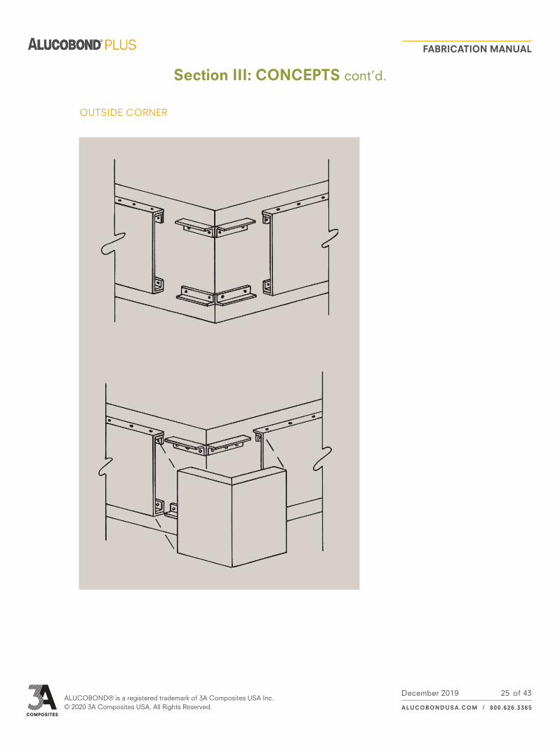
OUTSIDE CORNER
Section III: CONCEPTS cont’d.
25

December 2019ALUCOBOND® is a registered trademark of 3A Composites USA Inc. © 2020 3A Composites USA. All Rights Reserved.
FABRICATION MANUAL
ALUCOBONDUSA.COM / 800.626.3365
of 43
SIGNAGE ELEMENT
SIGN CAN
ALUCOBOND MATERIAL
ONE SIDE
ALUCOBOND MATERIAL
TWO SIDES SHEET METAL SIGN CAN
Section III: CONCEPTS cont’d.
26

December 2019ALUCOBOND® is a registered trademark of 3A Composites USA Inc. © 2020 3A Composites USA. All Rights Reserved.
FABRICATION MANUAL
ALUCOBONDUSA.COM / 800.626.3365
of 43
MULTI-PLANE ELEMENTS
SHEET METAL SIGN CAN
ALUCOBOND MATERIAL
Section III: CONCEPTS cont’d.
27

December 2019ALUCOBOND® is a registered trademark of 3A Composites USA Inc. © 2020 3A Composites USA. All Rights Reserved.
FABRICATION MANUAL
ALUCOBONDUSA.COM / 800.626.3365
of 43
SYMMETRICAL SIGN
Section III: CONCEPTS cont’d.
28

December 2019ALUCOBOND® is a registered trademark of 3A Composites USA Inc. © 2020 3A Composites USA. All Rights Reserved.
FABRICATION MANUAL
ALUCOBONDUSA.COM / 800.626.3365
of 43
Section IV: OFF-LINE FINISHING
On many projects that involve ALUCOBOND PLUS material, a small quantity of “custom color” panels are often required. Because of the limited quantity, it is often not practical to obtain the “custom color” from the factory and post painting is required. Several of the paint manufacturers have tested their products over the standard finishes coil coated by 3A Composites USA Inc. and also over anodized material. Following is a list of the Paint Supplier, Coil Coat Finish and the materials needed for post painting.
Painting should be done by qualified applicators with experience in this type of application.
The first step in the post painting process is an assessment of the substrate concerning the cleaning, pretreat-ing and priming required prior to application of the finish. There are no standard procedures for all possible situations due to the variety and condition of the surface to be painted. Before painting, testing should be done on a small area to determine that the preparation, application, and adhesion of the finish are satisfactory. The coating adhesion between the post paint finish and the original coating must be carefully evaluated using common coating adhesion testing procedures. Also, color/gloss matching needs to be evaluated to provide an acceptable final appearance. If testing indicates poor adhesion, do not proceed. Contact your coating repre-sentative or ALUCOBOND PLUS Technical Services.
Before painting, always check the coating manufacturer’s application guidelines and follow the specific instructions shown on the product data sheet and application instructions. For specific recommendations or questions, contact your coating representative.
Surfaces to be painted must be clean, dry and free of dust, dirt, oil, grease and foreign contaminants. Clean the surface according to the paint manufacturer application guidelines.
If recommended by the paint manufacturer, the curing of paint may be accelerated through a moderate increase in temperature. For composite material, the temperature must never exceed 140o F.
Where sanding is necessary, do not sand through coating to metal substrate.
A. Painting
1. PREPARATION
2. APPLICATION
29

December 2019ALUCOBOND® is a registered trademark of 3A Composites USA Inc. © 2020 3A Composites USA. All Rights Reserved.
FABRICATION MANUAL
ALUCOBONDUSA.COM / 800.626.3365
of 43
TABLE 3
Section IV: OFF-LINE FINISHING cont’d.
COIL COATING FINISH SURFACE PREPARATION PRIMER TOP COAT
AKZO NOBEL 800-233-3301 or 770-662-8464
Polyester
Degrease with Grip-Gard® M-600 Wax & Grease Re-mover. Sand surface with 320-360 grit paper dry Grip-Gard®
Degrease with Grip-Gard® M-600 Wax & Grease Remover
Grip-Gard® HSGrip-Gard® PlusMeta-Flex®
Duranar® Degrease with Grip-Gard® M-600 Wax & Grease Re-mover. Sand surface with 320-360 grit paper dry Grip-Gard® HB Surfacer
Grip-Gard®Grip-Gard® HSGrip-Gard® PlusMeta-Flex®
Duranar® XLE Degrease with Grip-Gard® M-600 Wax & Grease Re-mover. Sand surface with 320-360 grit paper dry Grip-Gard® HB Surfacer
Grip-Gard®Grip-Gard® HSGrip-Gard® PlusMeta-Flex®
Megaflon® Degrease with Grip-Gard® M-600 Wax & Grease Remover
Grip-Gard®Grip-Gard® HSGrip-Gard® PlusMeta-Flex®
Clear Anodized Degrease with Grip-Gard® M-600 Wax & Grease Re-mover. Sand surface with 320-360 grit paper dry Grip-Gard® Washprimer Grip-Gard®
BENJAMIN MOORE & CO. 800-334-0400
Polyester Duranar® Duranar® XL & Anodized
M15 Bonding Primer M22 Urethane Alkyd Gloss Enamel, others also available
CARBIT PAINT CO. 312-280-2300
Polyester Duranar® Duranar® XLEMegaflon®Clear Anodized
Clean surfaces with a 50/50 blend of isopropyl alcohol and water
Carbithane 11® SeriesCarbithane 12® Series
DUPONT INDUSTRIAL COATINGS 800-338-7668
Polyester MegaflonClear Anodized
Scuff sand with red Scotch Brite pad, clean with H-69 isopropyl alcohol
Imron® 333 Line Polyure-thane Enamel, Imron® 1.2 Waterborne Copolymer WG
Polyester Duranar® Duranar® XLEMegaflon®Clear Anodized
Scuff sand with red Scotch Brite pad, clean with H-69 isopropyl alcohol
Imron® 1.5 Waterborne Copolymer WF
Imron® 1.5 Waterborne Copolymer WG
Polyester®Duranar®Duranar® XLMegaflon®Clear Anodized
Scuff sand with red Scotch Brite pad, clean with H-69 isopropyl alcohol
Corlar® VHS 90P Epoxy Mastic Primer
Imron® 333 Line Polyure-thane Enamel
30

December 2019ALUCOBOND® is a registered trademark of 3A Composites USA Inc. © 2020 3A Composites USA. All Rights Reserved.
FABRICATION MANUAL
ALUCOBONDUSA.COM / 800.626.3365
of 43
TABLE 3 - conTinuEd
COIL COATING FINISH SURFACE PREPARATION PRIMER TOP COAT
MATTHEWS PAINT CO. 800-323-6593 or 262-947-0700
Polyester Duranar®Duranar® XLEMegaflon®
Wipe down with 45330SP Speed Prep Cleaner, abrade with 320/400 grit or red Scotch Brite pad, then wipe again with Speed Prep Cleaner
MAP® VOC MAP®Satin VOC MAP®
ONE SHOT, LLC 219-949-1684
PolyesterMegaflon®
Lightly scuff sand with gray Scotch Brite pad and wipe down with isopropyl alcohol
5005 Acrylic Bonding Primer White
1 SHOT Lettering Enamels, CHROMATIC Bulletin Colors
Duranar®Duranar® XLE
Lightly scuff sand with gray Scotch Brite pad and wipe down with isopropyl alcohol
1 SHOT Lettering Enamels, CHROMATIC Bulletin Colors
Clear Anodized Lightly scuff sand with gray Scotch Brite pad and wipe down with isopropyl alcohol
5005 Acrylic Bonding Primer White, 4331011 TiCote Clear Primer Flat
1 SHOT Lettering Enamels, CHROMATIC Bulletin Colors
PPG INDUSTRIES 800-441-9695
Polyester®Duranar®Duranar® XLMegaflon®
Lightly scuff sand and remove all forms of contamina-tion, clean with solvent
PPG Duracryl® Acrylic Lacquer
T.J. RONAN PAINT CORP. 800-247-6626 or 718-292-1100
PolyesterDuranar®Duranar® XLEMegaflon®Clear Anodized
Wipe with isopropyl alcohol (91%)
Metro Vinyl Primer (water borne), Universal Primer, Sticktite White Primer
Bulletin Color,Lettering Enamel,Aquacote (water borne)
SHERWIN-WILLIAMS 700-331-7979
Polyester Duranar®Duranar® XLE
DTM Bonding Primer DTM Acrylic coating Metala-tex semi-gloss coating
Clear Anodized DTM Wash Primer DTM Acrylic coating Metala-tex semi-gloss coating
Polyester Duranar®Duranar® XLEMegaflon®Clear Anodized
Cleaning per SSPC-SP1 (solvent cleaning) Bond-Plex water based acrylic coating
SPRAYLAT CORP. 800-336-1936 or 914-699-3035
PolyesterDuranar® Must be sanded or primed Series 20/30 Wash Primer Series 20 Acrylic Lacquer
Series 30 Polyurethane
Duranar® XLEAnodized Clean contaminate free Series 20/30 Wash Primer Series 20 Acrylic Lacquer
Series 30 Polyurethane
Polyester®Duranar®Duranar® XLMegaflon®
Scuff sand using Scotch Brite pad Polycryl
Clear Anodized Series 20/30 Wash Primer Polycryl
Section IV: OFF-LINE FINISHING cont’d.
31

December 2019ALUCOBOND® is a registered trademark of 3A Composites USA Inc. © 2020 3A Composites USA. All Rights Reserved.
FABRICATION MANUAL
ALUCOBONDUSA.COM / 800.626.3365
of 43
Anodized or coil coated ALUCOBOND PLUS material can easily be screen printed. Any screen printing inkused must be cured by air drying, jet drying under 40 seconds at a maximum air or panel temperature of250o F, or UV cured at maximum panel temperature of 140o F. Temperature or dwell times in excess of theselimits may cause warping or distortion of the panel.
It is recommended to contact the ink manufacturer to determine the products best suited for a particular application.
Proper surface preparation prior to screen printing is essential. Wipe the printing surface with isopropyl alcohol to remove any surface residue; allow isopropyl alcohol to dry (visual inspection) and screen print as usual.
ALUCOBOND PLUS material are often screen-printed when used in the signage and display industry. Although it would be impossible for any ink or panel manufacturers to run a trial using all of the different types of inks available, 3A Composites USA Inc. has worked in cooperation with several different ink manufacturers to determine the performance of various inks on standard finish material.
As always, it is strongly suggested that a trial run of any ink process to be completed prior to commitment to a full production run. 3A Composites USA Inc. recommends that you consult with the ink manufacturer if there are any questions regarding the use of a particular ink and to test any application prior to initiating a production run.
The information found in Table 4 is the summary from the recommendations of screen print ink manufactur-ers for printing on Polyester, Duranar, Duaranar XL, and Anodized ALUCOBOND PLUS. Please use these recommendations as a guide only. No warranty, guarantees, or claims concerning the practicality, mer-chantability, or fitness of any off-line coating material or process are made by 3A Composites USA Inc.
B. Screen Printing
TABLE 4
POLYESTER DURANAR DURANAR XL ANODIZED
NAZ-DAR/KC917-422-1888
3200 w/5% NB 80 3200 w/5% NB 80 3200 w/5% NB 80 7200
3600 w/5% NB 80 3600 w/5% NB 80 3600 w/5% NB 80
System 2 System 2 System 2
7200 7200 7200
9700 9700
SERICOL913-342-4060
Fascure Satin
Gloss Poly Gloss Poly Gloss Poly
MR Matte MR Matte MR Matte
Polydyne Polydyne2 Polydyne2
Uvipak PE Uvipak PE Uvipak PE
Fast Dry Enamel Fast Dry Enamel Fast Dry Enamel Fast Dry Enamel
HGXE HGXE HGXE
Polyscreen TP w/ catalyst Polyscreen TP w/ catalyst
Polyscreen TP w/ catalyst
Polyscreen TP w/ catalyst
SP Enamel SP Enamel SP Enamel
Fascure
Fascure PB
PEL
Plastical
Section IV: OFF-LINE FINISHING cont’d.
32

December 2019ALUCOBOND® is a registered trademark of 3A Composites USA Inc. © 2020 3A Composites USA. All Rights Reserved.
FABRICATION MANUAL
ALUCOBONDUSA.COM / 800.626.3365
of 43
Painted ALUCOBOND PLUS material of any thickness can be repaired. Any small areas damaged duringfabrication or erection may be repaired using materials recommended by the particular paint system manu-facturer supplying the off-line paint finish. These minor repairs are generally done with an automotive glazingputty between the primer and finish coat. The glazing putty is applied to the sanded, dented area. Allowapplied putty to dry, then sand, prime and paint much like the methods used in an auto body repair.
Larger and deeper dents may be filled using an automotive polyester body filler. Once again, auto body repair practices are used. Generally, a larger dented area is sanded with a rough grit paper and drilled with small diameter holes and then filled, sanded, primed and painted.
This method of repair should be used only after all fabrication is done on the panel. Any rolling, drilling, shearing, or punching operations through a filled area may cause damage to the repair.
C. Panel Repair
Section IV: OFF-LINE FINISHING cont’d.
33

December 2019ALUCOBOND® is a registered trademark of 3A Composites USA Inc. © 2020 3A Composites USA. All Rights Reserved.
FABRICATION MANUAL
ALUCOBONDUSA.COM / 800.626.3365
of 43
Section V: ENGINEERING
Deflections of ALUCOBOND PLUS material under load are demonstrated by the following charts. The chartsare developed to demonstrate the amount of spacing between supports across the short dimension of thepanel in comparison to the panel deflection. Deflections in excess of 2” should not be allowed as such ex-cess may stress the aluminum skin beyond allowable limits.
Charts 1 and 2 contain data relative to the use of 4mm ALUCOBOND PLUS material under two types of sup-port conditions where the panel is fixed or attached along two sides only: Single span with flexible ends andtwin span with flexible ends.
To determine support spacing, choose the chart for the type of support planned. At the bottom of the chart labeled “Space in Feet,” enter the chart with anticipated support spacing, then follow this value of spacing upward until it intersects the curve, labeled according to design windload. Read the corresponding deflection at the left side of the chart labeled “Deflection in Inches.” At no time should the intersection of the planned support distance and the windload be above the line marked “Maximum Tension.” Adjust anticipated design spacing and supports as needed to avoid exceeding “Maximum Tension.” If this deflection value exceeds the allowable deflection, adjust spacing accordingly.
Example:What is the maximum deflection of a sheet of 4mm ALUCOBOND PLUS material supported on two sides, every 3’-0” with flexible ends, under a windload of 40 psf?
Locate the chart for 4mm twin span condition. At the bottom of the chart find the “Spacing in Feet.” Follow the 3.00’ line upward until it intersects the 40 psf curve, then line over to the left side of the chart and read the “Deflection in Inches” of 1.150”.
A. Deflection
B. Windload Data
34

December 2019ALUCOBOND® is a registered trademark of 3A Composites USA Inc. © 2020 3A Composites USA. All Rights Reserved.
FABRICATION MANUAL
ALUCOBONDUSA.COM / 800.626.3365
of 43
Section V: ENGINEERING cont’d.
cHART 1 - WindLoAd cHART: 4MM, SinGLE SPAn
cHART 2 - WindLoAd cHART: 4MM, TWin SPAn SiMPLY SuPPoRTEd
35

December 2019ALUCOBOND® is a registered trademark of 3A Composites USA Inc. © 2020 3A Composites USA. All Rights Reserved.
FABRICATION MANUAL
ALUCOBONDUSA.COM / 800.626.3365
of 43
Thermal expansion should always be considered in designs using ALUCOBOND PLUS material. ALUCOBONDPLUS material has been tested and has a Rate of Expansion of 0.000158”/ft/o F. That translates into 1/8” move-ment in an 8 foot panel with a 100o F temperature change. Temperature differences must be considered betweenshop (fabrication) temperature and the highest or lowest temperature the panel is expected to achieve. An ex-ample of this concept is listed below. Care should always be taken to avoid restricting thermal movement of thepanel to eliminate unacceptable bowing and over-stressing of the fasteners. The coefficient for unlike materialsshould be considered in joint design.
Panel Length @ Shop Temperature: 10’ (120”)Panel Width @ Shop Temperature: 4’ (48”)
Maximum Panel Temperature (including reflected heat): 175o F
Minimum Panel Temperature: -20o FFabrication Shop Temperature: 60o F
Maximum Panel Lenth Dimensions
Maximum Panel Width Dimensions
+ Temperature change:Total Expansion:
- Temperature change:Total Contraction:
Panel Width at extreme temperature:
+ Temperature change:Total Expansion:
- Temperature change:Total Contraction:
Panel Width at extreme temperature:
175o F - 60o F = 115o F0.000158” x 10’ x 115o F = +0.1817”
60o F - (-20o F) = 80o F 0.000158” x 10’ x 80o F = 0.126”
9’ - 11 7/8” @ -20o F10’ - 0 3/16” @ -175o F
175o F - 60o F = 115o F 0.000158” x 4’ x 115o F = +0.07268”
60o F - (-20o F) = 80o F 0.000158” x 4’ x 80o F = 0.050”
3’ - 11 61/64” @ -20o F4’ - 0 5/64” @ 175o F
Total Panel Length change is .1817” + .126” = 0.3077” (From -20o F to 175o F)
Total Panel Width change is .07268” + .050” = 0.12268” (From -20o F to 175o F)
C. Thermal Expansion
Section V: ENGINEERING cont’d.
36

December 2019ALUCOBOND® is a registered trademark of 3A Composites USA Inc. © 2020 3A Composites USA. All Rights Reserved.
FABRICATION MANUAL
ALUCOBONDUSA.COM / 800.626.3365
of 43
ALUCOBOND PLUS material is an aluminum composite material (ACM) consisting of two cover sheets of.020” (nominal) gauge aluminum thermobonded to a solid, fire retardant core. ALUCOBOND PLUS meetsthe higher requirements of fire classifications while offering the proven product properties such as flatness,form-ability, durability and ease of fabrication. It is produced in 4mm core thicknesses in a continuous pro-cess. All material is supplied with a mill edge.
Bending StrengthThe following formula can be used to calculate bending stress:
Mb = Bending Moment t1 = Total Thickness
Z = Section Modulus tc = Thickness of Core
W = Width
D. Technical Data
Mb
Z
6t1 x Mb
(t13 - tc
3) W
Sb = =
Section V: ENGINEERING cont’d.
37
Standard Test Method*
ASTM C-365
ASTM C-393
ASTM C-393
ASTM D-790
ASTM D-790
ASTM D-790
ASTM D-790
ASTM D-790
ASTM D-790
ASTM D-638
ASTM D-638
ASTM D-638
ASTM D-638
ASTM D-732
ASTM D-732
ASTM C-518
ASTM C-518
ASTM C-518
ASTM D-648
ASTM D-648
ASTM C-273
ASTM C-297
ASTM D-1781
ASTM E-90
ASTM E-90
ASTM C-272
ASTM D-696
ASTM D-635
ASTM D-1929
ASTM D-1929
ASTM E-84
ASTM E-84
CAN/ULC-S102
CAN/ULC-S102
Mechanical
Mechanical
Mechanical
Mechanical
Mechanical
Mechanical
Mechanical
Mechanical
Mechanical
Mechanical
Mechanical
Mechanical
Mechanical
Mechanical
Mechanical
Thermal
Thermal
Thermal
Thermal
Thermal
Bond Integrity
Bond Integrity
Bond Integrity
Acoustical
Acoustical
Physical
Physical
Fire Performance
Fire Performance
Fire Performance
Fire Performance
Fire Performance
Fire Performance
Fire Performance
9291 psi
24,720 psi
22,732 psi
1891 ksi
18,573 psi
1815 ksi
17,703 psi
6667 psi
6930 psi
2930 ksi
7750 psi
6570 psi
14.2%
2198 lbs.
4615 psi
U=6.5 Btu/hr ft2 oF
R=0.16
6.25
185oF
189oF
765 psi
1016 psi
> 22.5 in-lb/in
30
24
0.003%
1.11x10⁻⁵ in/in oF
Classified CC1
783oF
784oF
< 25
< 100
< 25
< 100
Flatwise Compression Strength (Ultimate)
Core Shear Properties (Perpendicular) Ultimate Facing Bending Stress
Core Shear Properties (Parallel) Ultimate Facing Bending Stress
Flexural Modulus (Perpendicular)
Ultimate Flexural (Perpendicular)
Flexural Modulus (Parallel)
Ultimate Flexural (Parallel)
Yield Flexural Stress (Perpendicular)
Yield Flexural Stress (Parallel)
Modulus of Elasticity (Perpendicular)
Tensile Strength (Perpendicular)
Tensile Yield at 0.2% Offset (Perpendicular)
Elongation (Perpendicular)
Punching Shear (Maximum Shear Load)
Punching Shear (Shear Strength)
Thermal Conductivity
Thermal Resistance
Thermal Conductance
Deflection Temperature - Perpendicular
Deflection Temperature - Parallel
Shear Test in Flatwise Plane (Ultimate Core Shear Strength)
Tensile Bond Strength Test in Flatwise Plane (Ultimate)
Bond Integrity
Sound Transmission (STC)
Sound Transmission (OITC)
Water Absorption
Coefficient of Linear Thermal Expansion
Rate of Burning
Ignition Temperature - Self
Ignition Temperature - Flash
Surface Burning Characteristics (Flame Spread)
Surface Burning Characteristics (Smoke Development)
Surface Burning Characteristics (Flame Spread)
Surface Burning Characteristics (Smoke Development)
Description Category 4mm
*The ASTM (American Society for Testing & Materials) Standard Test Method defines the way a test is performed and the precision of the result. The result of the test is then used to assess compliance with a standard specification.

December 2019ALUCOBOND® is a registered trademark of 3A Composites USA Inc. © 2020 3A Composites USA. All Rights Reserved.
FABRICATION MANUAL
ALUCOBONDUSA.COM / 800.626.3365
of 43
Temperature ResistanceWithstands environmental temperature changes from -55o F to + 175o F. Changes dimensionally 0.000158”per foot per degree Farenheit. The coefficient of linear expansion is governed by the aluminum cover sheets.
Bond Integrity ALUCOBOND PLUS material has been tested to ASTM D-1781 for bond integrity, simulating its resistance to delamination. The following minimum values have been established:
Bond Strength: 214 PSI (Vertical Pull)/ASTM C-297Peel Strength: 115 Nmm/mm o ASTM D-1781
No appreciable loss of bond strength has been determined due to normal weather conditions.
Sound Transmission & Vibration Characteristics Sound Transmission Class for ALUCOBOND PLUS material has been determined by ASTM E-90. Vibration damping loss factor was determined using the procedure of ASTM STP-378.
Loss Factor @ 100 HZ STC No.4mm: .280 28
D. Technical Data cont’d.
Section V: ENGINEERING cont’d.
38

December 2019ALUCOBOND® is a registered trademark of 3A Composites USA Inc. © 2020 3A Composites USA. All Rights Reserved.
FABRICATION MANUAL
ALUCOBONDUSA.COM / 800.626.3365
of 43
Section VI: PROCESSING
ALUCOBOND PLUS material should always be stored in a cool dry area where temperatures are relativelystable. Excessive temperature fluctuations may cause condensation to form on the stored sheets, possiblyresulting in permanent surface damage, especially on anodized material. Do not allow moisture to reachstored material.
Ideally, crates of ALUCOBOND PLUS material should be stored horizontally with adequate support to preventsagging, and not more than four skids high; or if the panels are 16’ or longer, not more than four skids high.Long-term storage with the panels sagging could create a permanent bow in the material. However, smallquantities of material may be stored on edge if adequately supported with an “A” frame rack. The “A” frammust have a solid base and back rest.
Several approaches can be used for ALUCOBOND PLUS material fabrication tables. These depend primarilyon need, cost, and space.
Vacuum or suction tables can be built with minimal expense and used effectively to speed up processing.Vacuum tables can be hand built utilizing PVC pipes, an industrial-type vacuum, and a porous top surface, asshown in Figure 26.
Tables should be well supported and laterally stable. The surface needs to be capable of being easily cleaned.The material used for the surface should be of a type that will not accumulate chips and other debris thatcould damage the surface of the sheets.
The use of spring clamps, screw clamps, and “C” clamps should always be done in conjunction with a flat, orother flat spacers, to avoid point compression on the ALUCOBOND PLUS material. Point clamping may causea dimpling in the surface. The flat bar can also be used as a straight edge for routing or cutting. Care shouldbe taken to avoid shifting of the panel while fabricating.
Avoid sliding the panels as they are placed on or removed from the table.
A. Storage
B. Fabricating Tables
Figure 26 - Simple Vacuum Table
5’ Approx.
10’ Approx.
TOP VIEW
Porous Mold Board
Plywood Frame
5 to 7 PSI Vacuum
39

December 2019ALUCOBOND® is a registered trademark of 3A Composites USA Inc. © 2020 3A Composites USA. All Rights Reserved.
FABRICATION MANUAL
ALUCOBONDUSA.COM / 800.626.3365
of 43
Section VI: PROCESSING cont’d.
Masking prior to fabrication is highly recommended to avoid surface damage. Under most circumstances,masking can be applied at the factory. If masking is applied at the fabrication point, the paint manufacturershould be consulted for compatibility. Incorrect masking selection may damage the panel finish. For standardpolyester finishes, polyvinyl or Polyethylene film is recommended. Adhesive strength should be of the leastamount available and tested to ensure compatibility with the surface finish. Applicators of sufficient quality toapply a smooth bubbleless film are needed since trapped air bubbles can leave a permanent mark on the paintfinish (reference Figure 27).
Caution should be taken when the fabricated product is exposed to ultraviolet light. Masking should be removed immediately after installation. Certain masking films are not compatibile with anodized surfaces and one should consult the suppluer prior to use. Although this masking material protects the surface from minor scratches and dirt accumulation, some markers will penetrate and stain the painted surface.
C. Masking
Figure 27 - Masking Techniques
Air Bubble Masking
40

December 2019ALUCOBOND® is a registered trademark of 3A Composites USA Inc. © 2020 3A Composites USA. All Rights Reserved.
FABRICATION MANUAL
ALUCOBONDUSA.COM / 800.626.3365
of 43
Section VII: SOURCES
The following list of products and sources is for your reference, and is not intended as a complete listing of either satisfactory products and materials or of possible sources of supply.
1. Two Part-Adhesives
Dymax Corporation51 Greenwoods RoadTorrington, CT 06790860-626-6326
National Starch & Chemical Corp.Finderne Avenue Bridgewater, NJ 08807908-685-5000
Sika Corporation 201 Polito Ave. Lyndhurst, NJ 07071201-933-8800
2. Construction AdhesivesConstruction & Sub Floor Adhesive
Sovereign Engineered Adhesives123 W. Bartges StreetAkron, OH 44331-1081800-323-5158
TACC56 Air Station Industrial Park Rockland, MA 02370800-503-6991
3. Structural Adhesives
Dow ChemicalProduct InformationP.O. Box 0994Midland, MI 48686-0997989-496-6000
GE Silicon Products260 Hudson River Road Waterford, NY 12188800-332-3390
LEECH Products, Inc. P.O. Box 2147Hutchinson, KS 67504-2147620-669-0145
4. Other (Epoxy, Etc.)
Lord Corp.Industrial Adhesives Dept.2000 West Grandview Blvd.Erie, PA 16509814-868-3611
1. Custom Routing Blades and Cutters, Saw Blades
Drake Corp.1913 N. Van Buren StreetHuntingburg, IN 47542812-683-2101
2. Drill Bits
(Standard: High speed steel bits)
ABC Sign Products, Inc. 2028 Southeast Frontage Road Fort Collins, CO 80525970-482-5225800-248-9889
APCO388 Grant Street Southeast Atlanta, GA 30312-2227404-688-9000800-215-4039
Excellart Sign Products, LLC1654 S. Lone Elm Road Olathe, KS 66061913-764-2364800-627-9044
Futura Industries Corp. P.O. Box 160350 Building H-11 Freeport CenterFreeport Center Station Clearfield, UT 84016-0350801-773-6282
Signcomp2925-A Walkent CourtGrand Rapids, MI 49544616-784-0405877-784-0405
1. Bond on Stud
Midwest FastenersP.O. Box 73238Cleveland, OH 44193937-866-0463
2. Stud Welding
Southern Stud Weld3910-H North FreewayHouston, TX 77022713-691-0897
A. Adhesives B. Blades, Router Bits and Drill Bits
C. Extrusions
D. Fasteners
41

of 43July 2019ALUCOBOND® is a registered trademark of 3A Composites USA Inc. © 2019 3A Composites USA. All Rights Reserved.
FABRICATION MANUAL
ALUCOBONDUSA.COM / 800.626.3365
Section VII: SOURCES
1. Porous Mold Board
Diamond Supply Inc.200 Dalton Ave.P.O. Box 5115Charlotte, NC 28206704-376-2125
1. Press Brake(Available through commercial sources)
2. Pyramid Rollers(Available through commercial sources)
3. Routers
Black & DeckerSkilSearsMiller Falls
4. Panel Saws
Colonial Saw122 Pembroke StreetP.O. Box AKingston, MA 02364781-585-4364
W.W. Thayer Co. 1444 Hoelzer Court Pacific, MO 63069636-257-3311
HOLZ-HER U.S. Inc. 5120 Westinghouse Blvd.Charlotte, NC 28273704-587-3400Fax: 704-587-3412
5. Multiple OperationsRip/V - Grooving Saws
Multiscore15-7157 Honeyman St.Delta British Columbia V4G1E2604-946-6130
Bischof & Klein 2 Anderson St.Monmouth Beach, NJ 07750732-229-8126
IVEX Novacel55 Tower Rd.Newton, MA 02464610-268-3698
Main TapeP.O. Box 379Plymouth, WI 53073800-858-0481
AKZO Nobel 5555 Spalding Dr. Norcross, GA 30092770-662-8464
Beckers Specialty Corporation 2526 Delta Lane Elk Grove Village, IL 60007847-766-3555
Dura Coat Products26655 Peoples RoadMadison, AL 35756256-353-7800
Sherwin Williams 101 W. Prospect Ave. Cleveland, OH 44115800-474-3794
PPG Industries #1 PPG Place Pittsburgh, PA 15272800-441-9695
T.J Ronan Paint Corp.749 East 135th StreetBronx, NY 10454718-292-1100800-247-6626
Sherwin Williams 10 Midland Building101 Prospect Ave.Cleveland, OH 44115216-566-2151
Spraylat Corporation 716 South Columbus Ave.Mount Vernon, NY 10550-4795914-699-3030
E. Fabricating Tables
F. Machinery
H. Paints
G. Masking
42

December 2019ALUCOBOND® is a registered trademark of 3A Composites USA Inc. © 2020 3A Composites USA. All Rights Reserved.
FABRICATION MANUAL
ALUCOBONDUSA.COM / 800.626.3365
of 43
Section VII: SOURCES
Dow Corning Corp.Product InformationP.O. Box 0994Midland, MI 48686-0997989-496-6000
General Electric Co. 260 Hudson River Road Waterford, NY 12188800-332-3390
IPS Corporation 455 W. Victoria StreetCompton, CA 90220800-898-3300 / 310-898-3300Fax: 310-898-3392
Lord Corporation Industrial Adhesives Division 2000 West Grandview Blvd. P.O. Box 10038Erie, PA 16509814-868-3611
Pecora Corp. 165 Wambold RoadHarleysville, PA 19438800-523-6688
Rhodia 259 Prospect Plains Rd.Cranbury, NJ 08512-CN7500609-860-4000800-634-5705
Schnee Morehead Inc. 111 North Nursery RoadIrving, TX 750601-800-TRUST SM972-438-9111Fax: 972-554-3939
Sika Corporation 201 Polito Ave.Lyndhurst, NJ 07071201-933-8800
Tremco Corp. 3735 Green RoadBeachwood, OH 44122216-292-5000
Naz-Dar925 Roselawn Ave.Toronto, ON M6B1B7Canada416-789-5111
Naz-Dar 8501 Hedge Lane Terrace Shawnee, KS 66227913-422-1888
Sericol 1101 West Cambridge Circle DriveKansas City, KS 66110913-342-4060
3M Industrial Tape and Specialties Div.900 Bush Avenue St. Paul, MN 55144800-362-3550
Avery DennisonSpecialty Tape Division 250 Chester Street Painesville, OH 44077440-639-2600
Mactac Technical Products Division4560 Darrow Road Stow, OH 44224-1898800-401-5005
Saint Gobain Performance Plastics Corp.One Sealants Park Granville, NY 12832800-724-0883518-642-2200
I. Sealants J. Screen Print Inks
K. Tapes
43